

Toyota Camry 2007-2009 Service Manual - CAN_Communication
CAN COMMUNICATION – CAN COMMUNICATION SYSTEM
CAN COMMUNICATION SYSTEM
PRECAUTION
1. STEERING SYSTEM HANDLING PRECAUTIONS
(a) Care must be taken when replacing parts. Incorrect
replacement could affect the performance of the
steering system and result in hazardous driving.
2. SRS AIRBAG SYSTEM HANDLING PRECAUTIONS
(a) This vehicle is equipped with an SRS
(Supplemental Restraint System) which includes
parts such as the driver airbag and front passenger
airbag. Failure to carry out service operations in the
correct sequence could cause unexpected SRS
deployment during servicing and may lead to a
serious accident. Before servicing (including
removal or installation of parts, inspection or
replacement), be sure to read the precautionary
notice for the Supplemental Restraint System (See
page RS-1).
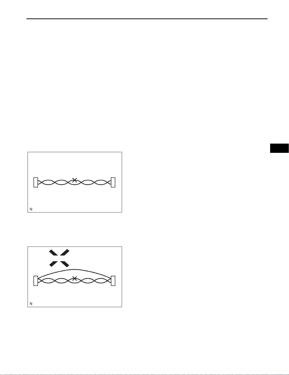
3. BUS WIRE REPAIR
(a) After repairing a bus wire with solder, wrap the
repaired part with vinyl tape.
NOTICE:
• The CANL bus wire and CANH bus wire must
be installed together at all times.
• When installing, make sure that they are
twisted.
• CAN bus wires are likely to be influenced by
F045104
noise if the bus wires are not twisted.
• The difference in length between the CANL
bus wire and CANH bus wire should be within
100 mm (3.937 in.).
• Leave approximately 80 mm (3.150 in.) loose
in the twisted wires around the connector.
CA–1
CA
Bypass Wire
(b) Do not use bypass wiring between the connectors.
NOTICE:
The protective effect of the twisted wire harness
will be lost if you use bypass wiring.
F045105E01

CA–2
Service Wire
CAN COMMUNICATION – CAN COMMUNICATION SYSTEM
4. CONNECTOR HANDLING
(a) When checking resistance with a tester, insert the
tester probes from the backside (harness side) of
the connector.
Tester Probe
F045106E01
(b) Use a service wire to check the connector if it is
impossible to check continuity from the rear of the
connector.
5. EXPRESSIONS OF IGNITION SWITCH
The type of ignition switch used on this model differs
according to the specifications of the vehicle.
The expressions listed in the table below are used in this
section.
CA
F045107E13
Expression
Ignition switch off LOCK Off
Ignition switch on (IG) ON On (IG)
Ignition switch on (ACC) ACC ON (ACC)
Engine start START Start
Ignition Switch (Position) Engine Switch (Condition)
Switch Type
CAN COMMUNICATION – CAN COMMUNICATION SYSTEM
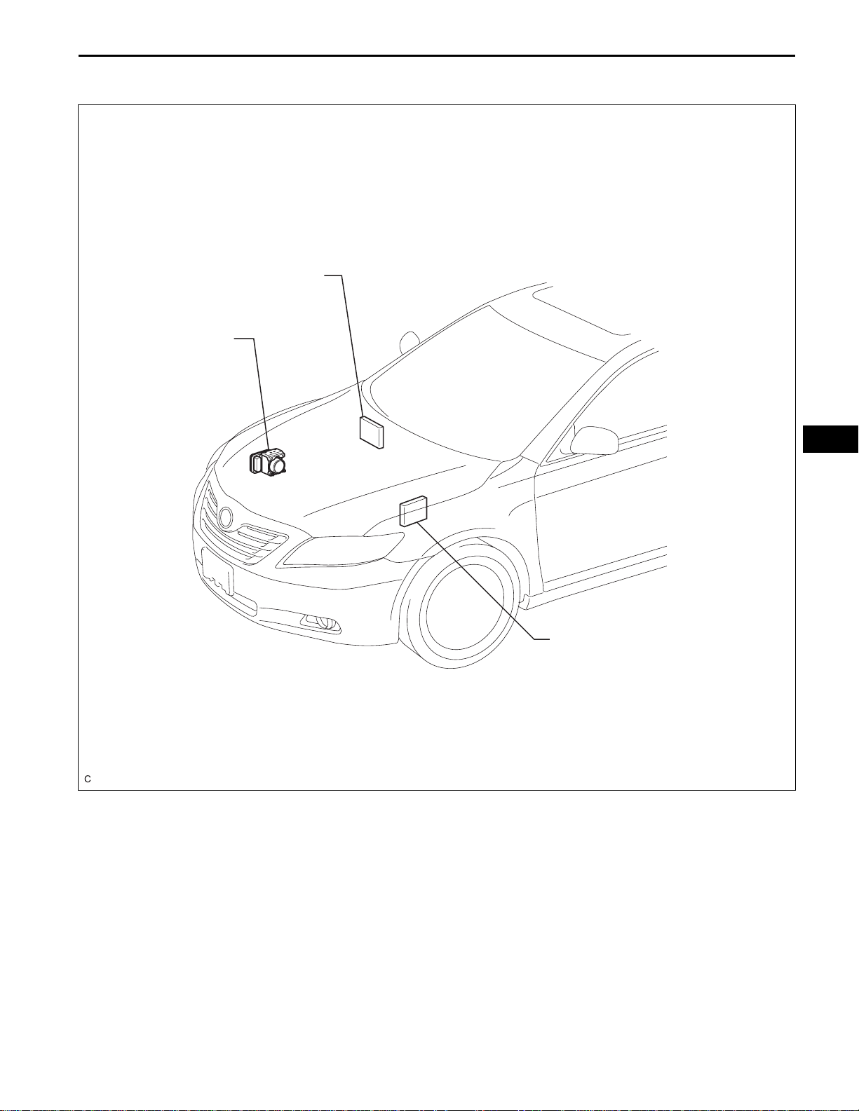
PARTS LOCATION
ECM (2GR-FE)
SKID CONTROL ECU
WITH ACTUATOR
CA–3
ECM (2AZ-FE)
CA
C136705E03
CA–4
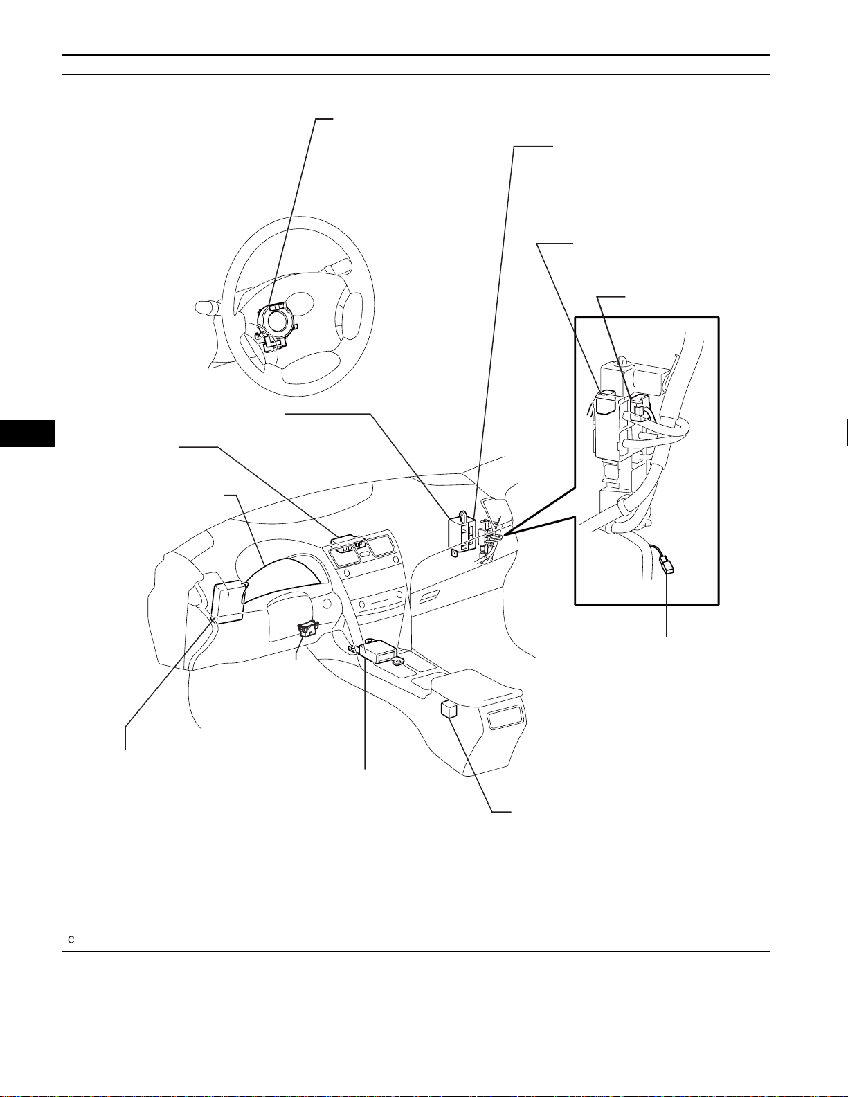
CAN COMMUNICATION – CAN COMMUNICATION SYSTEM
STEERING ANGLE SENSOR
CERTIFICATION ECU*
NO. 2 CAN J/C (A40)
NO. 2 CAN J/C (E41)
A/C AMPLIFIER
CA
NO. 1 CAN J/C
COMBINATION METER
ACCESSORY GATEWAY
DLC3
MAIN BODY ECU
CENTER AIRBAG SENSOR
ASSEMBLY
YAW RATE SENSOR
*: With Smart Key System
C133236E01
CAN COMMUNICATION – CAN COMMUNICATION SYSTEM
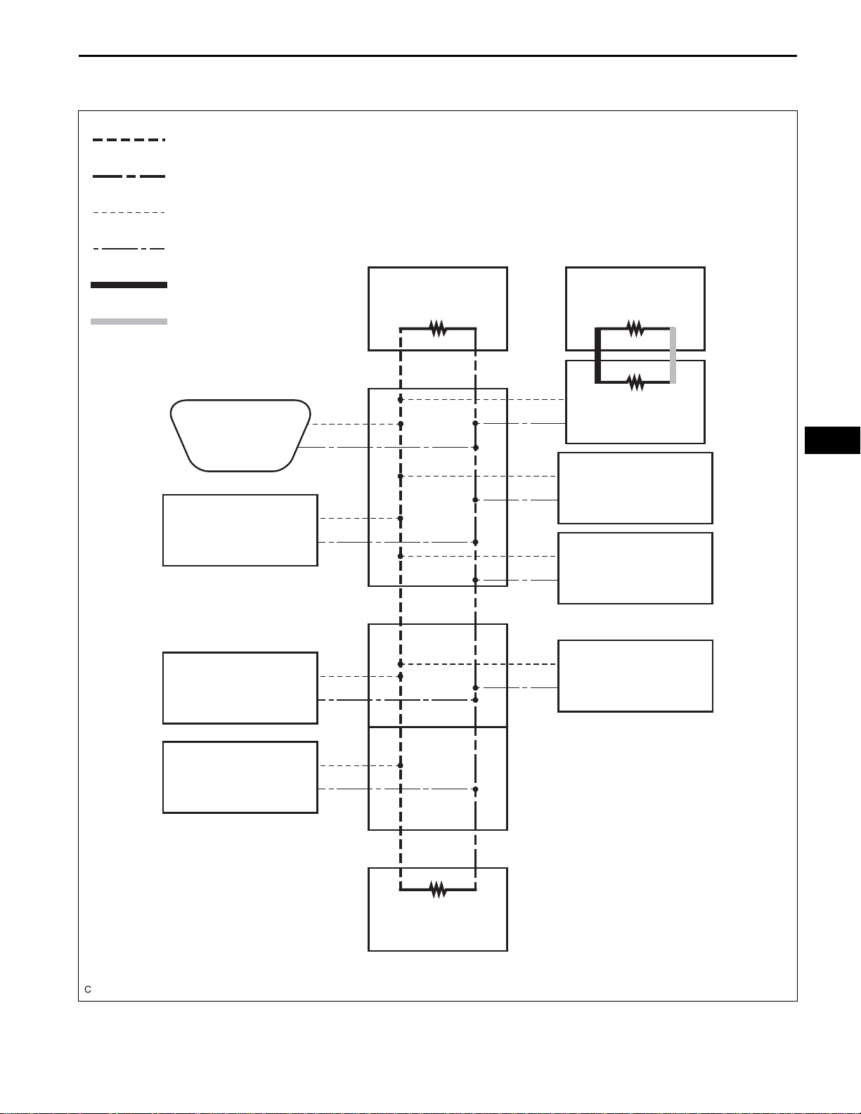
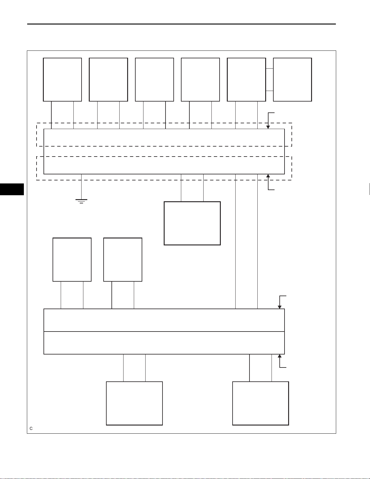
: CAN Main Bus Wire (CANH)
CA–5
SYSTEM DIAGRAM
: CAN Main Bus Wire (CANL)
: CAN Branch Wire (CANH)
: CAN Branch Wire (CANL)
: CAN MS Bus Wire (CANH)
: CAN MS Bus Wire (CANL)
No. 1 CAN J/C
DLC3
Steering Angle
Sensor*2
*1: with Smart Key System
*2: with VSC
Combination Meter Certification ECU*1
120 Ω120 Ω
120 Ω
Main Body ECU
CA
Yaw Rate Sensor*2
Center Airbag Sensor
Assembly
No. 2 CAN J/C (Rear of the Vehicle)
Accessory Gateway
Skid Control ECU
with Actuator
A/C Amplifier
No. 2 CAN J/C (Front of the Vehicle)
120 Ω
ECM
C136704E04

CA–6
CAN COMMUNICATION – CAN COMMUNICATION SYSTEM
HINT:
• The skid control ECU detects and stores steering angle
sensor and yaw rate sensor DTCs and allows DTC
communication by receiving information from the steering
angle sensor and yaw rate sensor.
CA

CAN COMMUNICATION – CAN COMMUNICATION SYSTEM
SYSTEM DESCRIPTION
1. BRIEF DESCRIPTION
(a) Two different CAN busses are used. The CAN
busses are classified into two types based on typical
communication speed.
The HS-CAN bus is a high-speed communication
bus that is used for powertrain, chassis, and some
body electrical communication. The HS-CAN bus is
referred to as the "CAN bus" and it operates at
speeds of approximately 500 kbps. Terminating
resistors for the HS-CAN bus are located in the
ECM and combination meter.
The MS-CAN bus is a medium-speed
communication bus that is used for body electrical
communication. The MS-CAN bus is referred to as
the "MS bus" and it operates at speeds of
approximately 250 kbps. Terminating resistors for
the MS-CAN bus are located in the main body ECU
and the certification ECU. The resistance of the MSCAN bus cannot be measured from the DLC3
connector.
Communication between these two networks is
handled via the main body ECU, which acts as a
gateway ECU.
(b) By pairing the CANH and CANL bus wires, the CAN
performs communication based on differential
voltage.
(c) Many ECUs (sensors) installed on the vehicle
operate by sharing information and communicating
with each other.
(d) The CAN has two resistors of 120 Ω which are
necessary to enable communication on the main
bus wire.
2. DEFINITION OF TERMS
(a) Main bus wire
(1) The main bus wire is a wire harness between
the two terminus circuits on the bus
(communication line).
(b) Branch wire
(1) The branch wire is a wire harness which
diverges from the main bus wire to an ECU or
sensor.
CA–7
CA

CA
CA–8
CAN COMMUNICATION – CAN COMMUNICATION SYSTEM
(c) Terminating resistors
(1) Two resistors of 120 Ω resistance are installed in
parallel across the ends of the CAN main bus
wires. They are called terminating resistors.
These resistors allow the changes of the voltage
differential between the CAN bus wires to be
accurately judged. To allow proper function of
CAN communication, it is necessary to have
both terminating resistors installed. Since the
two resistors are installed in parallel, a
measurement of resistance between the two
CAN bus wires should produce a reading of
approximately 60 Ω.
3. ECUS OR SENSORS WHICH COMMUNICATE
THROUGH CAN COMMUNICATION SYSTEM
(a) Skid control ECU with actuator
(b) Air conditioning amplifier
(c) Main body ECU
(d) Combination meter ECU
(e) Yaw rate sensor
(f) Steering angle sensor
(g) Center airbag sensor
(h) ECM
(i) Certification ECU (with smart key system)
(j) TCM
(k) Accessory gateway
4. DIAGNOSTIC CODE FOR CAN COMMUNICATION
SYSTEM
(a) DTCs for the CAN communication system are as
follows: U0101, U0073, U0100, U0123, U0124,
U0126, U0129, B1207, B1499, and B2326.
5. TROUBLESHOOTING REMARKS
(a) DTCs for the CAN communication system can be
checked using the intelligent tester via the CAN
VIM. The DLC3 is connected to the CAN
communication system, but no DTCs exist
regarding problems in the DLC3 or the DLC3 branch
wires. If there is trouble in the DLC3 or the DLC3
branch wires, ECUs on the CAN network cannot
output codes to the intelligent tester via the CAN
VIM.
(b) Trouble in the CAN buses (communication lines)
can be checked by measuring the resistance
between terminals of the DLC3. However, an open
circuit in a branch wire other than the DLC3 branch
wires cannot be checked from the DLC3.
NOTICE:
Do not insert the tester probes directly into the
DLC3. Be sure to use a service wires.

CAN COMMUNICATION – CAN COMMUNICATION SYSTEM
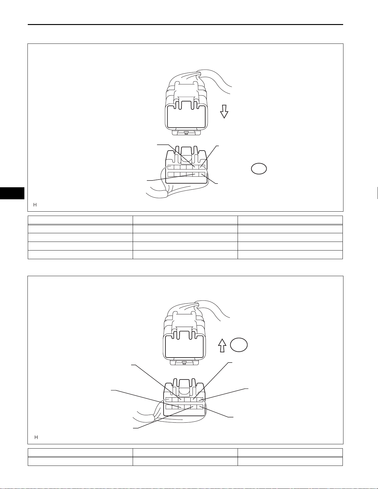
6. HOW TO DISTINGUISH THE CAN J/C CONNECTOR
(a) In the CAN communication system, the shape of all
connectors connected to the CAN J/C No. 1 is the
same. The connectors connected to the CAN J/C
No. 1 can be connecting side of the junction
connector.
HINT:
See "TERMINALS OF ECU" (See page CA-10) for
bus wire color or the type of connecting surface.
CA–9
CA

CA–10
1
NEXT
2
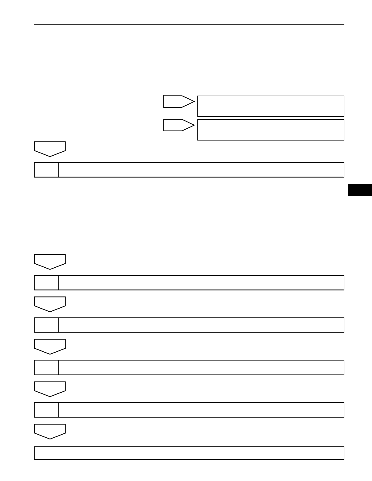
CAN COMMUNICATION – CAN COMMUNICATION SYSTEM
HOW TO PROCEED WITH
TROUBLESHOOTING
NOTICE:
• DTCs for the CAN communication system are as
follows: U0101, U0073, U0100, U0123, U0124, U0126,
B1207, B1499, and B2326.
• Refer to troubleshooting of each system if DTCs
regarding the CAN communication system are not
output.
CHECK AND CLEAR DTCS
CHECK FOR INSTALLED SYSTEMS (ECUS & SENSORS) THAT ADOPT CAN
COMMUNICATION)
CA
(a) Check which of the following is adopted: SFI system,
NEXT
CHECK CAN BUS LINE
3
(a) Check the CAN bus wires (See page CA-65).
NEXT
CHECK INTELLIGENT TESTER
4
(a) Select "Communication Bus Check" (See page CA-25).
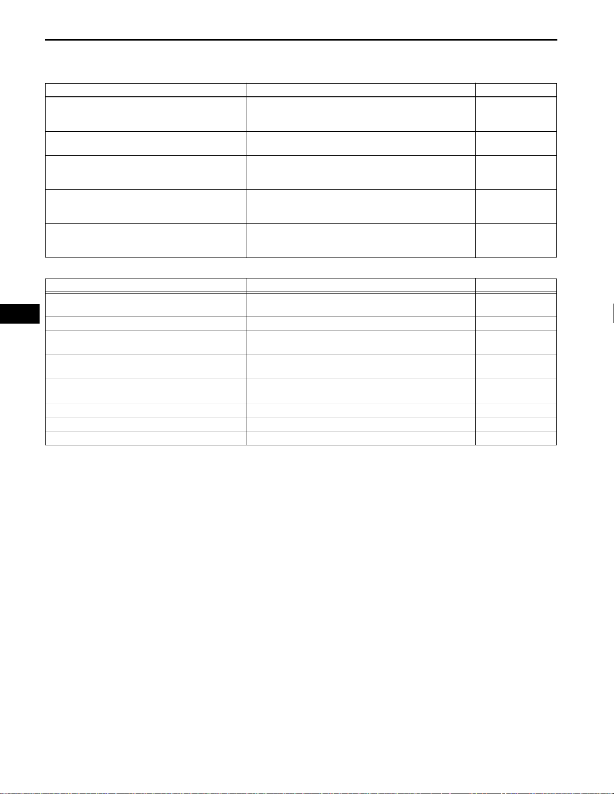
Result
Symptom Proceed See procedure
All the ECUs and sensors connected to the CAN communication
system are displayed on the screen.
An ECU or sensor not connected to the CAN communication
system is displayed on the screen.
More than one of the ECUs and sensors not connected to the
CAN communication system are displayed on the screen. (If the
displayed ECUs and sensors are only those relating to the
"Engine" and "ECT", proceed to B.)
automatic transaxle system, brake control system,
supplemental restraint system, smart key system, air
conditioning system and meter / gauge system (See
page CA-25).
A Go to step 5
B CA-10
C CA-119
NOTICE:
• The systems (ECUs, sensors) that adopt CAN
communication vary depending on the vehicle
and option settings. Check which systems (ECUs,
sensors) are installed on the vehicle (See page
CA-25).
CAN COMMUNICATION – CAN COMMUNICATION SYSTEM
• Non-installed ECUs or sensors are not displayed.
Do not mistake ECUs that are not installed as
being in communication stop mode.
• If 2 or more ECUs or sensors are not displayed on
the intelligent tester, perform troubleshooting for
communication stop mode for each undisplayed
ECU or sensor. (Open in one side of the CAN
branch wires.)
CA–11
A
5
NEXT
DTC COMBINATION TABLE
B
C
(a) Confirm trouble according to the combination of output
DTCs regarding the CAN communication system (See
page CA-25).
HINT:
Previous CAN communication system DTCs may be the
cause if CAN communication system DTCs are output
and all ECUs and sensors connected to the CAN
communication system are displayed on the intelligent
tester "Communication Bus Check" screen.
GO TO "COMMUNICATION STOP MODE
TABLE"
GO TO "OPEN IN ONE SIDE OF CAN
BRANCH LINE"
CA
6
NEXT
7
NEXT
8
NEXT
9
NEXT
END
CIRCUIT INSPECTION
IDENTIFICATION OF PROBLEM
REPAIR OR REPLACE
CONFIRMATION TEST
CA
CA–12
CAN COMMUNICATION – CAN COMMUNICATION SYSTEM
PROBLEM SYMPTOMS TABLE
RESULT LIST OF HOW TO PROCEED WITH TROUBLESHOOTING:
Symptom Suspected area See page
The result of "HOW TO PROCEED WITH
TROUBLESHOOTING" is "Open in CAN Main Bus
Line"
The result of "HOW TO PROCEED WITH
TROUBLESHOOTING" is "Short in CAN Bus Line"
The result of "HOW TO PROCEED WITH
TROUBLESHOOTING" is "Short to +B in CAN Bus
Line"
The result of "HOW TO PROCEED WITH
TROUBLESHOOTING" is "Short to GND in CAN Bus
Line"
The result of "HOW TO PROCEED WITH
TROUBLESHOOTING" is "Open in One Side of CAN
Sub Bus Line"
COMMUNICATION STOP MODE TABLE:
Symptom Suspected area See page
"ABS/VSC/TRAC" is not displayed on the intelligent
tester (with VSC)
"A/C " is not displayed on the intelligent tester Air Conditioning Amplifier Communication Stop Mode CA-46
"Body/Gateway" is not displayed on the intelligent
tester
"Steering Angle Sensor" is not displayed on the
intelligent tester
"Yaw Rate/Deceleration Sensor" is not displayed on
the intelligent tester
"Engine" are not displayed on the intelligent tester ECM Communication Stop Mode CA-54
"Meter " is not displayed on the intelligent tester Combination Meter Communication Stop Mode CA-61
"SRS Airbag" is not displayed on the intelligent tester Center Airbag Sensor Communication Stop Mode CA-63
Open in CAN Main Bus Wire CA-69
Short in CAN Bus Wires CA-74
Short to B+ in CAN Bus Wire CA-89
Short to GND in CAN Bus Wire CA-104
Open in One Side of CAN Branch Wire CA-119
Skid Control ECU Communication Stop Mode CA-42
Main Body ECU Communication Stop Mode CA-57
Steering Angle Sensor Communication Stop Mode CA-49
Yaw Rate Sensor Communication Stop Mode CA-51
CAN COMMUNICATION – CAN COMMUNICATION SYSTEM
CA–13
TERMINALS OF ECU
NOTICE:
This section describes the standard CAN values for all
CAN related components.
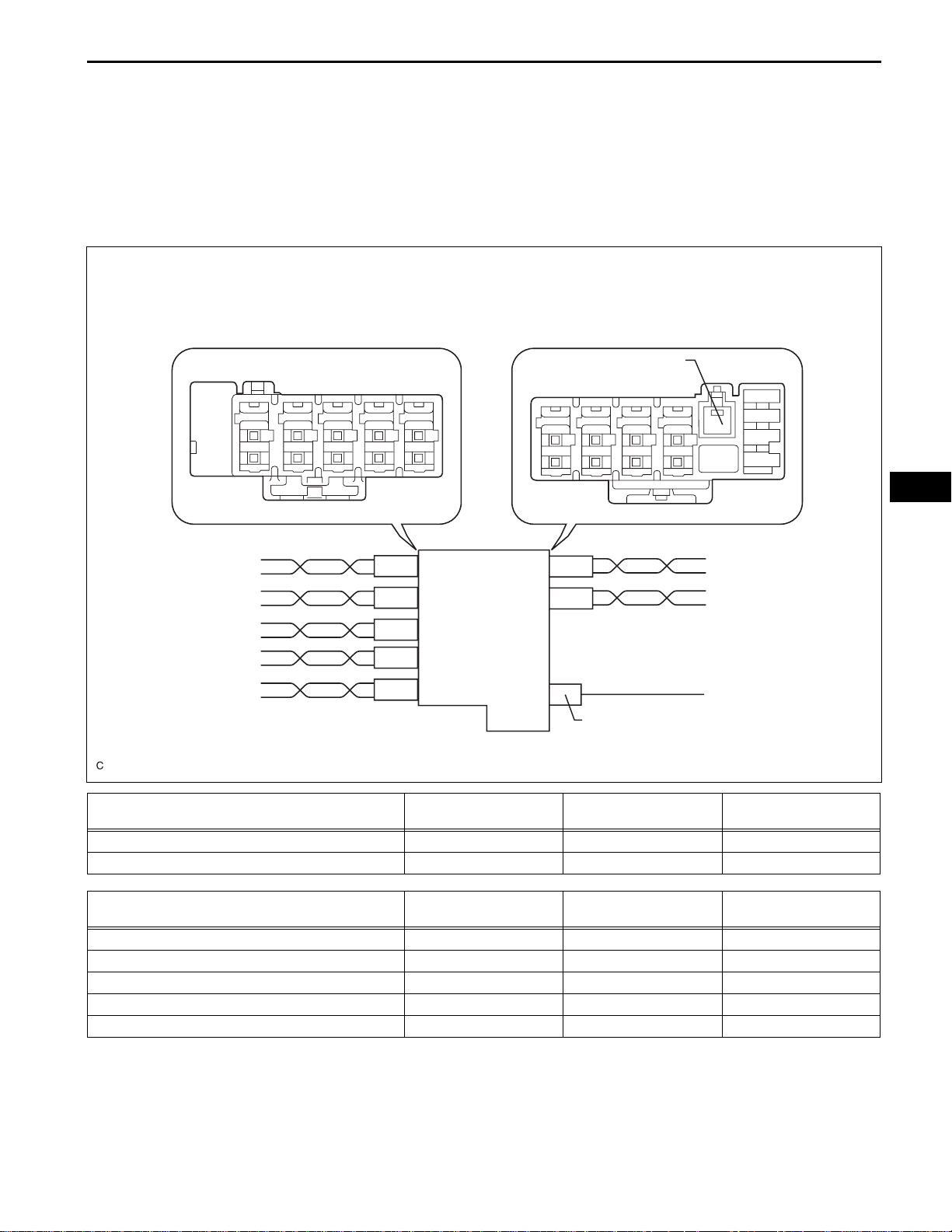
1. JUNCTION CONNECTOR (NO. 1 CAN J/C, NO. 2 CAN
J/C)
(a) No. 1 CAN J/C
No. 1 CAN J/C “B” side (without Earth Terminal): No. 1 CAN J/C “A” side (with Earth Terminal):
Earth Terminal
W
W
W
B
B
B
B
E46
E62
E63
E43
E42
E45
B
W
B
W
W
B
W
E44
Earth Terminal
No. 1 CAN J/C connectors ("A" side, with earth
terminal)
CAN Main Bus Wire (E42) White B W
Airbag Sensor Assembly Center (E45) Black B W
No. 1 CAN J/C connectors ("B" side, with earth
terminal)
Yaw Rate Sensor* (E46) Blue B W
DLC3 (E62) Gray B W
Steering Angle Sensor* (E63) Brown B W
Combination Meter (E43) White B W
Main Body ECU (E44) Black B W
Connector Color Wire Color (CAN-H) Wire Color (CAN-L)
Connector Color Wire Color (CAN-H) Wire Color (CAN-L)
CA
C137761E02
*: with VSC
CA–14
CAN COMMUNICATION – CAN COMMUNICATION SYSTEM
(b) No. 2 CAN J/C (FRONT OF THE VEHICLE)
No. 2 CAN J/C (Front of the Vehicle) Wire Harness View:
CANH
(for Skid Control ECU)
Front of the Vehicle
CANH
(for ECM)
CA
CANL
(for Skid Control ECU)
Terminals Wiring Color Connects to
A40-1 (CANH) B ECM (CANH)
A40-7 (CANL) W ECM (CANL)
A40-2 (CANH) B Skid Control ECU (CANH)
A40-8 (CANL) W Skid Control ECU (CANL)
(c) No. 2 CAN J/C (REAR OF THE VEHICLE)
No. 2 CAN J/C (Rear of the Vehicle) Wire Harness View:
A40
CANL
(for ECM)
C137762E02
Front of the Vehicle
E41
CANH
(for No. 1 CAN J/C)
CANL
(for No. 1 CAN J/C)
CANL
(for Accessory Gateway)
Terminals Wiring Color Connects to
E41-1 (CANH) B Accessory Gateway (CANH)
CANH
(for Accessory Gateway)
CANH
(for A/C Amplifier)
CANL
(for A/C Amplifier)
C137763E02

CAN COMMUNICATION – CAN COMMUNICATION SYSTEM
Terminals Wiring Color Connects to
E41-7 (CANL) W Accessory Gateway (CANL)
E41-2 (CANH) B A/C Amplifier (CANH)
E41-8 (CANL) W A/C Amplifier (CANL)
E41-4 (CANH) B No. 1 CAN J/C (CANH)
E41-10 (CANL) W No. 1 CAN J/C (CANL)
CA–15
CA
CA–16
CAN COMMUNICATION – CAN COMMUNICATION SYSTEM
(d) The connection diagram of the components which
are connected to the CAN J/C
CA
Sensor*2
CANH
CANL
DLC 3Yaw Rate
CANH CANL CANH CANL CANH CANL CANH
Steering
Angle
Sensor*2
No. 1 CAN J/C
Combination
Meter
CANH
Center Airbag
Sensor Assembly
CANL
Main Body
ECU
CANH
Certification
ECU*1
“B” Side (without Earth
Terminal)
CANL
CANL
“A” Side (with
Earth Terminal)
*1: with smart key system
Accessory
Gateway
A/C
Amplifier
CANH CANL
Skid Control ECU
with Actuator
*2: with VSC
Rear of the
Vehicle (E41)
CANH CANLCANH CANLCANH CANL
No. 2 CAN J/C
CANH
CANL
Front of the
Vehicle (A40)
ECM
C136707E02

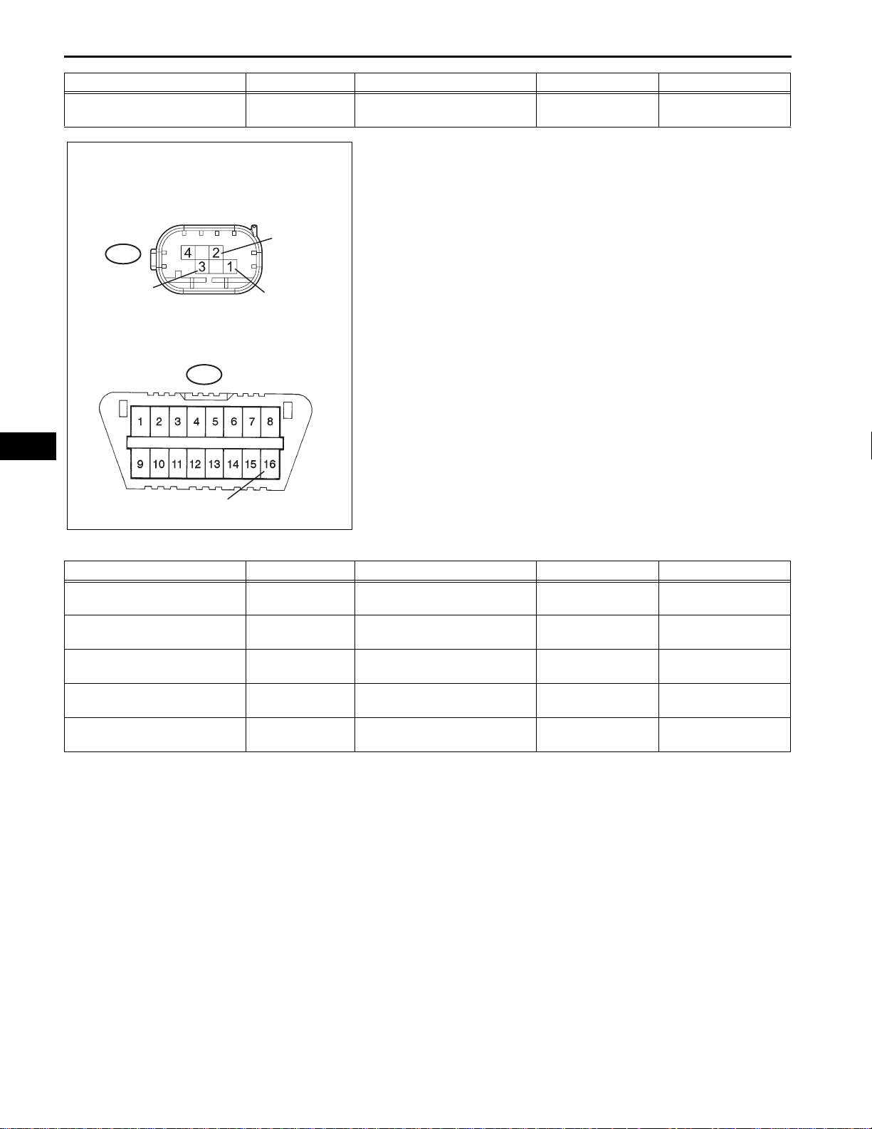
DLC3:
CG
CAN COMMUNICATION – CAN COMMUNICATION SYSTEM
2. DLC3
E10
CANH
(a) Measure the resistance according to the value(s) in
the table below.
CA–17
CANL
BAT
Standard resistance
Terminals Wiring Color Terminal Description Condition Specified Condition
E10-6 (CANH) - E10-14 (CANL) B - W
E10-6 (CANH) - E10-4 (CG) B - W-B
E10-14 (CANL) - E10-4 (CG) W - W-B
E10-6 (CANH) - E10-16 (BAT) B - L
E10-14 (CANL) - E10-16 (BAT) W - L
Skid Control ECU (Harness Side
Connector Front View):
A25
+BS
CANL
C125062E02
HIGH-level CAN bus wire -
LOW-level CAN bus wire
HIGH-level CAN bus wire -
Ground
LOW-level CAN bus wire -
Ground
HIGH-level CAN bus wire -
Battery positive
LOW-level CAN bus wire -
Battery positive
Ignition Switch off 54 to 69 Ω
Ignition Switch off 200 Ω or higher
Ignition Switch off 200 Ω or higher
Ignition Switch off 1 MΩ or higher
Ignition Switch off 1 MΩ or higher
3. SKID CONTROL ECU (w/o VSC)
(a) Disconnect the A25 connector from the skid control
ECU.
(b) Measure the resistance according to the value(s) in
the table below.
CA
CANHGND1
Standard resistance
Terminals Wiring Color Terminal Description Condition Specified Condition
A25-26 (CANH) - A25-15 (CANL) B - W
A25-26 (CANH) - A25-4 (GND1) B - W-B
A25-15 (CANL) - A25-4 (GND1) W - W-B
A25-26 (CANH) - A25-3 (+BS) B - L
A25-15 (CANL) - A25-3 (+BS) W - L
C131970E11
HIGH-level CAN bus wire -
LOW-level CAN bus wire
HIGH-level CAN bus wire -
Ground
LOW-level CAN bus wire -
Ground
HIGH-level CAN bus wire -
Battery positive
LOW-level CAN bus wire -
Battery positive
Ignition Switch off 54 to 69 Ω
Ignition Switch off 200 Ω or higher
Ignition Switch off 200 Ω or higher
Ignition Switch off 6 kΩ or higher
Ignition Switch off 6 kΩ or higher

CA–18
CAN COMMUNICATION – CAN COMMUNICATION SYSTEM
CA
Skid Control ECU Connector
Front View:
CANH
+BS
GND1
CANL
Standard resistance
Terminals Wiring Color Terminal Description Condition Specified Condition
A26-11 (CANH) - A26-25 (CANL) B - W
A26-11 (CANH) - A26-32 (GND1) B - W-B
A26-25 (CANL) - A26-32 (GND1) W - W-B
A26-11 (CANH) - A26-31 (+BS) B - L
A26-25 (CANL)- A26-31 (+BS) W - L
A26
E069126E52
4. SKID CONTROL ECU WITH ACTUATOR (w/ VSC)
(a) TMC made
(1) Disconnect A26 connector from the skid control
ECU.
(2) Measure the resistance according to the
value(s) in the table below.
HIGH-level CAN bus wire -
LOW-level CAN bus wire
HIGH-level CAN bus wire -
Ground
LOW-level CAN bus wire -
Ground
HIGH-level CAN bus wire -
Battery positive
LOW-level CAN bus wire -
Battery positive
Ignition Switch off 54 to 69 Ω
Ignition Switch off 200 Ω or higher
Ignition Switch off 200 Ω or higher
Ignition Switch off 6 kΩ or higher
Ignition Switch off 6 kΩ or higher
Skid Control ECU (Harness Side
Connector Front View):
A60
+BS CANL
GND1
CANH
Standard resistance
Terminals Wiring Color Terminal Description Condition Specified Condition
A60-35 (CANH) - A60-14 (CANL) B - W
A60-35 (CANH) - A60-4 (GND1) B - W-B
A60-14 (CANL) - A60-4 (GND1) W - W-B
A60-35 (CANH) - A60-3 (+BS) B - L
A60-14 (CANL)- A60-3 (+BS) W - L
C136493E10
(b) TMMK made
(1) Disconnect the A60 connector from the skid
control ECU.
(2) Measure the resistance according to the
value(s) in the table below.
HIGH-level CAN bus wire -
LOW-level CAN bus wire
HIGH-level CAN bus wire -
Ground
LOW-level CAN bus wire -
Ground
HIGH-level CAN bus wire -
Battery positive
LOW-level CAN bus wire -
Battery positive
Ignition Switch off 54 to 69 Ω
Ignition Switch off 200 Ω or higher
Ignition Switch off 200 Ω or higher
Ignition Switch off 6 kΩ or higher
Ignition Switch off 6 kΩ or higher

CAN COMMUNICATION – CAN COMMUNICATION SYSTEM
CA–19
Steering Angle Sensor Wire Harness View:
CANH
CANL
Standard resistance
Terminals Wiring Color Terminal Description Condition Specified Condition
E17-10 (CANH) - E17-9 (CANL) B - W
E17-10 (CANH) - E17-2 (ESS) B - W-B
E17-9 (CANL) - E17-2 (ESS) W - W-B
E17-10 (CANH) - E17-3 (BAT) B - W
E17-9 (CANL) - E17-3 (BAT) W - W
E17
BAT
ESS
G026357E15
5. STEERING ANGLE SENSOR (W/ VSC)
(a) Disconnect the E17 connector from the steering
angle sensor.
(b) Measure the resistance according to the value(s) in
the table below.
HIGH-level CAN bus wire -
LOW-level CAN bus wire
HIGH-level CAN bus wire -
Ground
LOW-level CAN bus wire -
Ground
HIGH-level CAN bus wire -
Battery positive
LOW-level CAN bus wire -
Battery positive
Ignition Switch off 54 to 69 Ω
Ignition Switch off 200 Ω or higher
Ignition Switch off 200 Ω or higher
Ignition Switch off 6 kΩ or higher
Ignition Switch off 6 kΩ or higher
CA
Yaw Rate Sensor Connector Front View:
CANL
E34
GND
CANH
DLC3:
E10
G026641E19
Standard resistance
6. YAW RATE SENSOR (W/ VSC)
(a) TMC made
(1) Disconnect the E34 connector from the yaw rate
sensor.
(2) Measure the resistance according to the
value(s) in the table below.
BAT
Terminals Wiring Color Terminal Description Condition Specified Condition
E34-3 (CANH) - E34-2 (CANL) B - W
E34-3 (CANH) - E34-1 (GND) B - W-B
E34-2 (CANL) - E34-1 (GND) W - W-B
E34-3 (CANH) - E10-16 (BAT) B - O
HIGH-level CAN bus wire -
LOW-level CAN bus wire
HIGH-level CAN bus wire -
Ground
LOW-level CAN bus wire -
Ground
HIGH-level CAN bus wire -
Battery positive
Ignition Switch off 54 to 69 Ω
Ignition Switch off 200 Ω or higher
Ignition Switch off 200 Ω or higher
Ignition Switch off 6 kΩ or higher
CA–20
Terminals Wiring Color Terminal Description Condition Specified Condition
E34-2 (CANL) - E10-16 (BAT) W - O
CAN COMMUNICATION – CAN COMMUNICATION SYSTEM
CANL
E65
LOW-level CAN bus wire -
Battery positive
(b) TMMK made
(1) Disconnect the E34 connector from the yaw rate
sensor.
(2) Measure the resistance according to the
value(s) in the table below.
Ignition Switch off 6 kΩ or higher
CA
CANH
GND
E10
BAT
Standard resistance
Terminals Wiring Color Terminal Description Condition Specified Condition
E65-3 (CANH) - E65-2 (CANL) B - W
E65-3 (CANH) - E65-1 (GND) B - W-B
E65-2 (CANL) - E65-1 (GND) W - W-B
E65-3 (CANH) - E10-16 (BAT) B - O
E65-2 (CANL) - E10-16 (BAT) W - O
C136716E01
HIGH-level CAN bus wire -
LOW-level CAN bus wire
HIGH-level CAN bus wire -
Ground
LOW-level CAN bus wire -
Ground
HIGH-level CAN bus wire -
Battery positive
LOW-level CAN bus wire -
Battery positive
Ignition Switch off 54 to 69 Ω
Ignition Switch off 200 Ω or higher
Ignition Switch off 200 Ω or higher
Ignition Switch off 6 kΩ or higher
Ignition Switch off 6 kΩ or higher
7. CENTER AIRBAG SENSOR ASSEMBLY
(a) Disconnect the E30 connector from the center
airbag sensor assembly.
CAN COMMUNICATION – CAN COMMUNICATION SYSTEM
CA–21
Center Airbag Sensor
Wire Harness View :
E30
E10
BAT
Standard resistance
E1
CANH
CANL
C125063E03
(b) Measure the resistance according to the value(s) in
the table below.
CA
Terminals Wiring Color Terminal Description Condition Specified Condition
E30-13 (CANH) - E30-22 (CANL) B - W
E30-13 (CANH) - E30-25 (E1) B - W-B
E30-22 (CANL) - E30-25 (E1) W - W-B
E30-13 (CANH) - E10-16 (BAT) B - L
E30-22 (CANL) - E10-16 (BAT) W - L
ECM:
HIGH-level CAN bus wire -
LOW-level CAN bus wire
HIGH-level CAN bus wire -
Ground
LOW-level CAN bus wire -
Ground
HIGH-level CAN bus wire -
Battery positive
LOW-level CAN bus wire -
Battery positive
8. ECM
(a) 2AZ-FE
CANH
Ignition Switch off 54 to 69 Ω
Ignition Switch off 200 Ω or higher
Ignition Switch off 200 Ω or higher
Ignition Switch off 6 kΩ or higher
Ignition Switch off 6 kΩ or higher
A24
CANL
A107881E28
(1) Disconnect the A24 connector from the ECM.

CA–22
CAN COMMUNICATION – CAN COMMUNICATION SYSTEM
(2) Measure the resistance according to the
value(s) in the table below.
Standard resistance
Terminals Condition Specified Condition
A24-41 (CANH) - A29-49 (CANL) Ignition Switch off 108 to 132 Ω
CA
ECM Wire Harness View:
A24
BATT
CANH
CANL
C24
E1
Standard resistance
Terminals Wiring Color Terminal Description Condition Specified Condition
A24-41 (CANH) - A24-49 (CANL) B - W
A24-41 (CANH) - C24-104 (E1) B - W-B
A24-49 (CANL) - C24-104 (E1) B - W-B
A24-41 (CANH) - A24-20 (BATT) B - Y
A24-49 (CANL) - A24-20 (BATT) W - Y
C136709E05
(3) Measure the resistance according to the
value(s) in the table below.
HIGH-level CAN bus wire -
LOW-level CAN bus wire
HIGH-level CAN bus wire -
Ground
LOW-level CAN bus wire -
Ground
HIGH-level CAN bus wire -
Battery positive
LOW-level CAN bus wire -
Battery positive
Ignition Switch off 108 to 132 Ω
Ignition Switch off 200 Ω or higher
Ignition Switch off 200 Ω or higher
Ignition Switch off 6 kΩ or higher
Ignition Switch off 6 kΩ or higher
(b) 2GR-FE
ECM:
CANH
CANL
(1) Disconnect the A55 connector from the ECM.
(2) Measure the resistance according to the
value(s) in the table below.
Standard resistance
Terminals Condition Specified Condition
A55-41 (CANH) - A55-49 (CANL) Ignition Switch off 108 to 132 Ω
A55
A107881E23

CAN COMMUNICATION – CAN COMMUNICATION SYSTEM
CA–23
ECM Wire Harness View:
BATT
A55
CANH
CANL
C55
E1
Standard resistance
Terminals Wiring Color Terminal Description Condition Specified Condition
A55-41 (CANH) - A55-49 (CANL) B - W
A55-41 (CANH) - C55-81 (EC) B - W-B
A55-49 (CANL) - C55-81 (EC) B - W-B
A55-41 (CANH) - A55-20 (BATT) B - Y
A55-49 (CANL) - A55-20 (BATT) W - Y
C136709E06
(3) Measure the resistance according to the
value(s) in the table below.
HIGH-level CAN bus wire -
LOW-level CAN bus wire
HIGH-level CAN bus wire -
Ground
LOW-level CAN bus wire -
Ground
HIGH-level CAN bus wire -
Battery positive
LOW-level CAN bus wire -
Battery positive
Ignition Switch off 108 to 132 Ω
Ignition Switch off 200 Ω or higher
Ignition Switch off 200 Ω or higher
Ignition Switch off 6 kΩ or higher
Ignition Switch off 6 kΩ or higher
CA
Air Conditioning Amplifier (Wire Harness
Side):
E38
B
GND
CANL
CANH
E124470E20
Standard resistance
Terminals Wiring Color Terminal Description Condition Specified Condition
E38-11 (CANH) - E38-12 (CANL) B - W
E38-11 (CANH) - E38-14 (GND) B - W-B
E38-12 (CANL) - E38-14 (GND) W - W-B
E38-11 (CANH) - E38-21 (B) B - GR
E38-12 (CANL) - E38-21 (B) W - GR
9. AIR CONDITIONING AMPLIFIER
(a) Check the harness side connector (E38) of the air
conditioning amplifier.
(1) Disconnect the connector (E38) from the air
conditioning amplifier.
(2) Measure the resistance according to the
value(s) in the table below.
HIGH-level CAN bus wire -
LOW-level CAN bus wire
HIGH-level CAN bus wire -
Ground
LOW-level CAN bus wire -
Ground
HIGH-level CAN bus wire -
Battery positive
LOW-level CAN bus wire -
Battery positive
Ignition Switch off 54 to 69 Ω
Ignition Switch off 200 Ω or higher
Ignition Switch off 200 Ω or higher
Ignition Switch off 6 kΩ or higher
Ignition Switch off 6 kΩ or higher
10. COMBINATION METER ECU
(a) Disconnect the F1 connector from the combination
meter.

CA–24
CAN COMMUNICATION – CAN COMMUNICATION SYSTEM
CA
Combination Meter (Component Side):
(b) Measure the resistance according to the value(s) in
the table below.
F1
CANL CANH
C133254E01
Standard resistance
Terminals Condition Specified Condition
F1-17 (CANH) - F1-18 (CANL) Ignition Switch off 108 to 132 Ω
Combination Meter (Wire Harness Side):
(c) Measure the resistance according to the value(s) in
the table below.
F1
B2
CANHCANL
Standard resistance
Terminals Wiring Color Terminal Description Condition Specified Condition
F1-17 (CANH) - F1-18 (CANL) B - W
F1-17 (CANH) - F1-12 (E2) B - W-B
F1-18 (CANL) - F1-12 (E2) B - W-B
F1-17 (CANH) - F1-2 (B2) B - R
F1-18 (CANL) - F1-2 (B2) B - R
C133255E01
HIGH-level CAN bus wire -
LOW-level CAN bus wire
HIGH-level CAN bus wire -
Ground
LOW-level CAN bus wire -
Ground
HIGH-level CAN bus wire -
Battery positive
LOW-level CAN bus wire -
Battery positive
Ignition Switch off 108 to 132 Ω
Ignition Switch off 200 Ω or higher
Ignition Switch off 200 Ω or higher
Ignition Switch off 6 kΩ or higher
Ignition Switch off 6 kΩ or higher
11. CERTIFICATION ECU (W/ SMART KEY SYSTEM)
(a) Disconnect the E58 connector from the certification
ECU.

CAN COMMUNICATION – CAN COMMUNICATION SYSTEM
CA–25
Certification ECU (Wire Harness Side):
E58
E
+B
CANHCANL
C136713E01
Standard resistance
Terminals Wiring Color Terminal Description Condition Specified Condition
E58-27 (CANH) - E58-28 (CANL) B - W
E58-27 (CANH) - E58-17 (E) B - W-B
E58-28 (CANL) - E58-17 (E) B - W-B
E58-27 (CANH) - E58-1 (+B) B - W
E58-28 (CANL) - E58-1 (+B) W - W
(b) Measure the resistance according to the value(s) in
the table below.
HIGH-level CAN bus wire -
LOW-level CAN bus wire
HIGH-level CAN bus wire -
Ground
LOW-level CAN bus wire -
Ground
HIGH-level CAN bus wire -
Battery positive
LOW-level CAN bus wire -
Battery positive
Ignition Switch off 108 to 132 Ω
Ignition Switch off 200 Ω or higher
Ignition Switch off 200 Ω or higher
Ignition Switch off 6 kΩ or higher
Ignition Switch off 6 kΩ or higher
CA
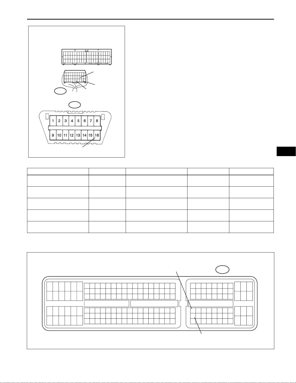
12. MAIN BODY ECU (INSTRUMENT PANEL J/B)
(a) Disconnect the E8 connector from the main body
ECU.

CA–26
Main Body ECU:
CAN COMMUNICATION – CAN COMMUNICATION SYSTEM
(b) Measure the resistance according to the value(s) in
the table below.
CA
CANN
E8
CANH
CANL
Standard resistance
Terminals Wiring Color Terminal Description Condition Specified Condition
E8-5 (CANH) - E8-6 (CANL) B - W
E8-16 (CANP) - E8-15 (CANN) W - L
Accessory Gateway:
CANP
C136714E01
HIGH-level CAN bus wire -
LOW-level CAN bus wire
HIGH-level CAN bus wire -
LOW-level CAN bus wire
Ignition Switch off 54 to 69 Ω
Ignition Switch off 108 to 132 Ω
13. ACCESSORY GATEWAY
(a) Measure the resistance according to the value(s) in
the table below.
CANL
CANH
C136715E02
Standard resistance
Terminals Terminal Description Condition Specified Condition
E61-6 (CANH) - E61-14 (CANL) HIGH-level CAN bus wire - LOW-level CAN bus wire Ignition Switch off 54 to 69 Ω

CAN COMMUNICATION – CAN COMMUNICATION SYSTEM
DIAGNOSIS SYSTEM
1. BUS CHECK
(a) Select "BUS CHECK" from the "OBD/MOBD
MENU" screen.
HINT:
The ECUs and sensors that are properly connected
to the CAN communication system can be displayed
using the intelligent tester via the CAN VIM.
C113760
(b) Press "ENTER" on the intelligent tester.
CA–27
C113761
CA
(c) The screen displays the ECUs and sensors that are
properly connected to the CAN communication
system.
HINT:
Properly connected ECUs or sensors that are not
displayed on the screen indicate that a
communication stop is occuring in the system,
sensor, or ECU which is not displayed.
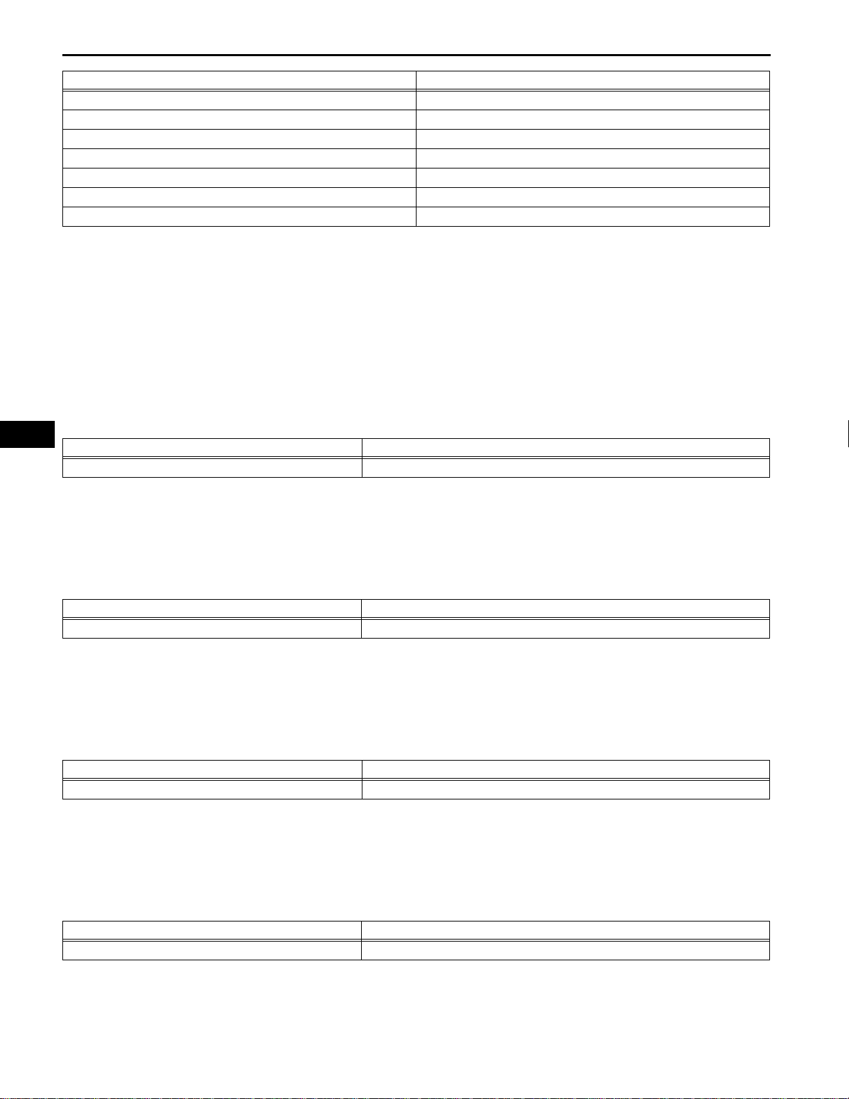
2. CHECK FOR INSTALLED SYSTEMS (ECUS AND
SENSORS) THAT USE CAN COMMUNICATION
(a) Systems (ECUs, sensors) that use CAN
communication vary depending on the vehicle's
optional equipment. Check which systems (ECUs,
sensors) are installed on the vehicle.
C113762
ECU/Sensor name Check method
ABS/VSC/TRC Installed on all vehicles
STEERING SENSOR With VSC system
YAW / DECELERAT With VSC system
ENGINE Installed on all vehicles
CA
CA–28
ECT With automatic transaxle
SRS AIRBAG Installed on all vehicles
A/C Installed on all vehicles
METER Installed on all vehicles
MAIN BODY Installed on all vehicles
ACCESSORY G/W With dealer option
SMART ACCESS/KEY With smart key system
CAN COMMUNICATION – CAN COMMUNICATION SYSTEM
ECU/Sensor name Check method
3. DTC TABLE BY ECU
HINT:
• For the CAN communication system, CAN
communication system DTCs stored in certain ECUs
can be displayed using the intelligent tester.
• If CAN communication system DTCs are output,
trouble cannot be determined only by the DTCs.
Perform troubleshooting according to "HOW TO
PROCEED WITH TROUBLESHOOTING" (See page
CA-8).
(a) ECM (2AZ-FE)
DTC No. Detection Item
U0101* High speed CAN Communication Bus
HINT:
• DTC communication is via the CAN
communication system.
• *: The ECM is malfunctioning if only U0101 is
output. Replace the ECM.
(b) ECM (2GR-FE)
DTC No. Detection Item
U0101* High speed CAN Communication Bus
HINT:
• DTC communication is via the CAN
communication system.
• *: The ECM is malfunctioning if only U0101 is
output. Refer to SFI system (See page ES-389).
(c) ECT (2AZ-FE)
DTC No. Detection Item
U0100* High speed CAN Communication Bus
HINT:
• DTC communication is via the CAN
communication system.
• *: The ECM is malfunctioning if only U0100 is
output. Replace the ECM.
(d) ECT (2GR-FE)
DTC No. Detection Item
U0100* High speed CAN Communication Bus
HINT:
• DTC communication is via the CAN
communication system.

CAN COMMUNICATION – CAN COMMUNICATION SYSTEM
• *: The ECM is malfunctioning if only U0100 is
output. Refer to Automatic Transaxle system
(See page AX-151).
(e) SKID CONTROL ECU (with VSC)
DTC No. Detection Item
U0073 Control Module Communication Bus Off
U0100 Lost Communication With ECM/PCM "A"
U0123 Lost Communication With Yaw Rate Sensor Module
U0124* Lost Communication With Lateral Acceleration Sensor Module
U0126 Lost Communication With Steering Angle Sensor Module
HINT:
• DTC communication is via the CAN
communication system.
• *: TMC made only
(f) SKID CONTROL ECU (without VSC)
DTC No. Detection Item
U0073 Control Module Communication Bus Off
HINT:
DTC communication is via the CAN communication
system.
(g) COMBINATION METER ECU
DTC No. Detection Item
U0100 Lost Communication With ECM/PCM "A"
U0129 Lost Communication with Brake System Control Mode
CA–29
CA
HINT:
DTC communication is via the CAN communication
system.
(h) AIR CONDITIONER AMPLIFIER
DTC No. Detection Item
B1499 Multiplex Communication Circuit
HINT:
DTC communication is via the CAN communication
system.
(i) MAIN BODY ECU (with smart key system)
DTC No. Detection Item
B1207* Certification ECU Communication Malfunction
B2326* CAN MS Bus Line Communication Malfunction
HINT:
• DTC communication is via the CAN
communication system.
• *: The main body ECU is malfunctioning if B1207
and/or B2326 are output alone. Refer to DTC
chart (See page AX-46).
(j) MAIN BODY ECU (without smart key system)
HINT:
Although the center airbag sensor is connected to
the CAN communication system, CAN
communication DTCs are not output.
CA
CA–30
DTC Trouble Mode
Output from Output DTC
Skid Control ECU
Combination Meter
ECU
Air Conditioner
Amplifier ECU
No DTC X X X X
CAN COMMUNICATION – CAN COMMUNICATION SYSTEM
(k) CENTER AIRBAG SENSOR
HINT:
Although the center airbag sensor is connected to
the CAN communication system, CAN
communication DTCs are not output.
(l) CERTIFICATION ECU
HINT:
Although the Main Body ECU is connected to the
CAN communication system, CAN communication
DTCs are not output.
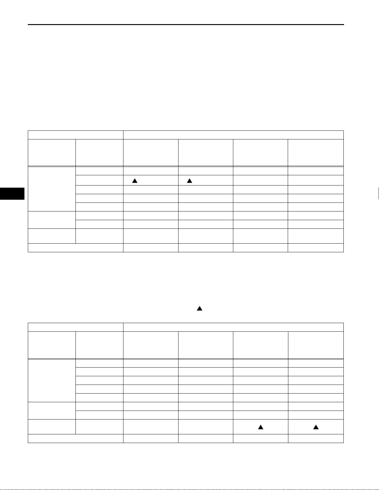
4. DTC COMBINATION TABLE
(a) with VSC SYSTEM
ECM Communication
Stop Mode
U0073 X X X X
U0100
U0123 X { X {
U0124* X { X {
U0126 X {{ X
U0100 { XXX
U0129 X { XX
B1499 X X X X
During driving During driving
Skid Control ECU
Communication Stop
Mode
Steering Angle
Sensor
Communication Stop
Mode
XX
Yaw Rate Sensor
Communication Stop
Mode
DTC Trouble Mode
Output from Output DTC Air Conditioner
U0073 X X X X
U0100 X X X X
Skid Control ECU
Combination Meter
ECU
Air Conditioner
Amplifier ECU
No DTC {{ XX
U0123 X X X X
U0124* X X X X
U0126 X X X X
U0100 X X X X
U0129 X X X X
B1499 X X
Amplifier ECU
Communication Stop
Mode
*: TMC made only.
HINT:
• {: Set
• X: Not set or may be set according to the
malfunctioning part when one side of the CAN
bus wire opens
• : Set under the condition shown in the table
above
Center Airbag
Sensor
Communication Stop
Mode
Main Body ECU
Communication Stop
Mode
Combination Meter
ECU Communication
Stop Mode
*: TMC made only.
HINT:
• {: Set
 Loading...