

Toyota Camry 2007-2009 Service Manual - Engine_Hood_Door
ENGINE HOOD / DOOR – HOOD
ED–1
HOOD
ON-VEHICLE INSPECTION
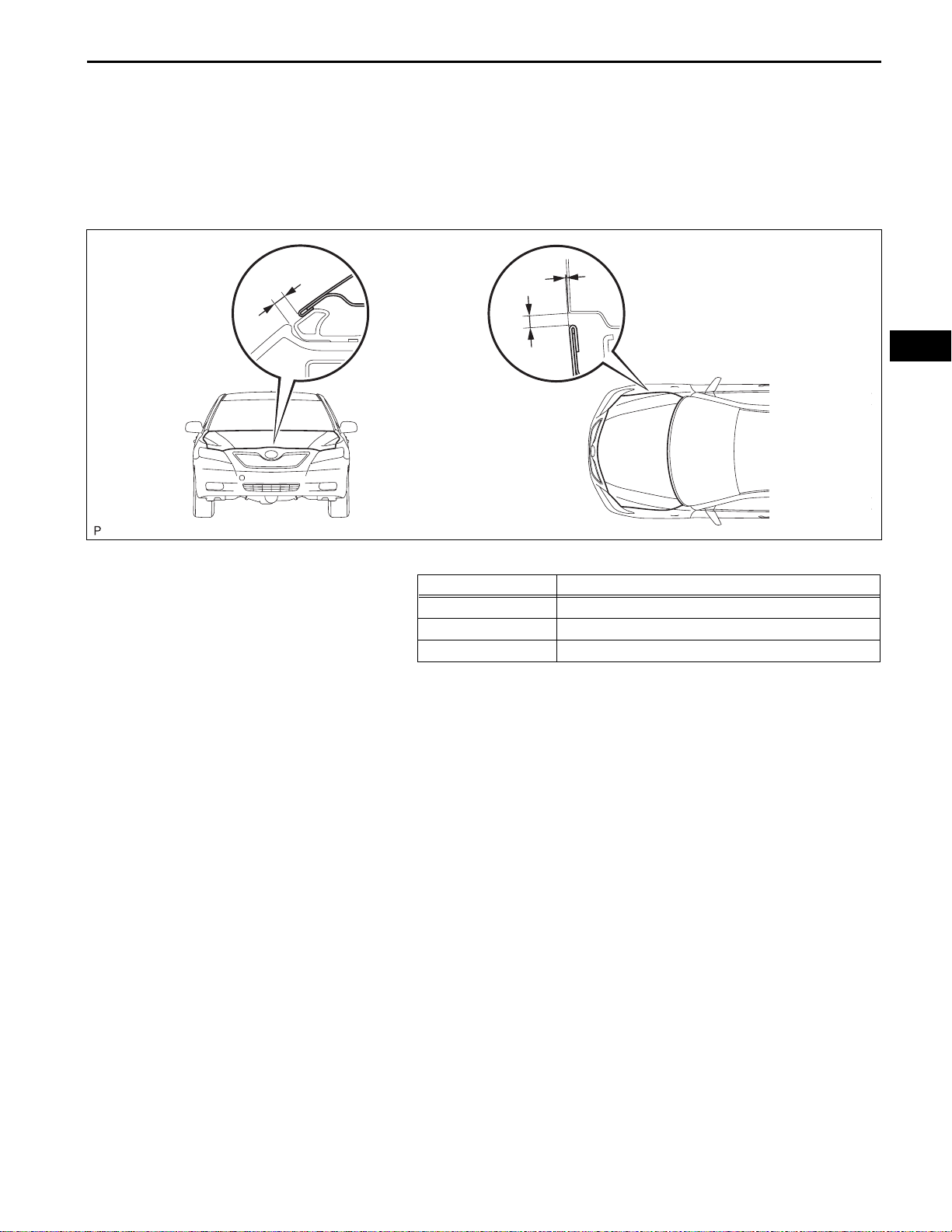
1. INSPECT HOOD SUB-ASSEMBLY
(a) Check that the clearance measurements of areas A
to C are within each standard range.
C
A
B
ED
Standard clearance
Area Measurement
A 2.3 to 5.3 mm (0.091 to 0.209 in.)
B 2.0 to 5.0 mm (0.079 to 0.197 in.)
C -1.4 to 1.6 mm (-0.055 to 0.063 in.)
B132821E01

ED–2
ENGINE HOOD / DOOR – HOOD
ADJUSTMENT
TMMK made:TMC made:
ED
Centering Bolt
Standard Bolt
Centering Bolt
Standard Bolt
B146065E01
HINT:
• Centering bolts are used to mount the hood hinge and
hood lock. The hood and hood lock cannot be adjusted
with the centering bolts on. Substitute the centering bolts
with standard bolts (with washers) when making
adjustments.
• A bolt without a torque specification is shown in the
standard bolt chart (See page SS-2).
1. REMOVE COOL AIR INTAKE DUCT SEAL (for 2GR-
FE) (See page ET-4)
2. REMOVE FRONT BUMPER ASSEMBLY (w/o Fog
Light) (See page ET-5)
3. REMOVE FRONT BUMPER ASSEMBLY (w/ Fog
Light) (See page ET-6)
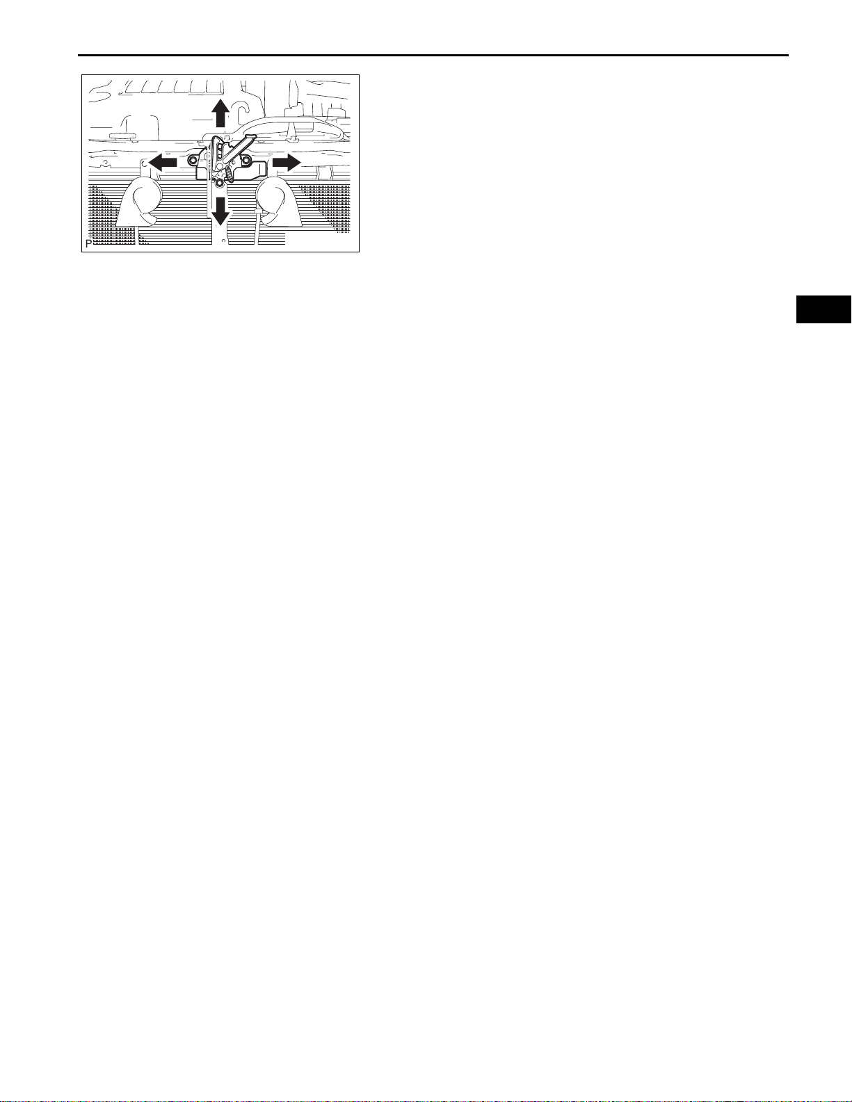
4. ADJUST HOOD SUB-ASSEMBLY
(a) Horizontally and vertically adjust the hood.
(1) Loosen the hood's 4 hinge bolts.
(2) Move the hood and adjust the clearance
between the hood and front fender.
(3) Tighten the hood's 4 hinge bolts after the
adjustment.
Torque: 13 N*m (133 kgf*cm, 10 ft.*lbf)
B132829
B132830
(b) Adjust the height of the hood front end using the
cushion rubber.
(1) Adjust the cushion rubber so that the height of
the hood and fender are aligned.
HINT:
Raise or lower the hood's front end by turning
the cushion rubber.
ENGINE HOOD / DOOR – HOOD
(c) Adjust the hood lock.
(1) Loosen the 3 bolts.
(2) Tighten the bolts after the adjustment.
Torque: 7.5 N*m (77 kgf*cm, 66 in.*lbf)
(3) Adjust the hood lock position so that the striker
can enter it smoothly.
5. INSTALL FRONT BUMPER ASSEMBLY (w/o Fog
Light) (See page ET-13)
ED–3
B132832
6. INST ALL FRONT BUMPER ASSEMBLY (w/ Fog Light)
(See page ET-14)
7. INSTALL COOL AIR INTAKE DUCT SEAL (for 2GRFE) (See page ET-14)
ED
8. VEHICLE PREPARATION FOR FOG LIGHT AIM (w/
Fog Light) (See page LI-79)
9. PREPARATION FOR FOG LIGHT AIMING (w/ Fog
Light) (See page LI-80)
10. FOG LIGHT AIMING INSPECTION (w/ Fog Light) (See
page LI-81)
11. FOG LIGHT AIMING ADJUSTMENT (w/ Fog Light)
(See page LI-82)
ENGINE HOOD / DOOR – HOOD SUPPORT ROD
BODYENGINE HOOD / DOOR
HOOD SUPPORT ROD
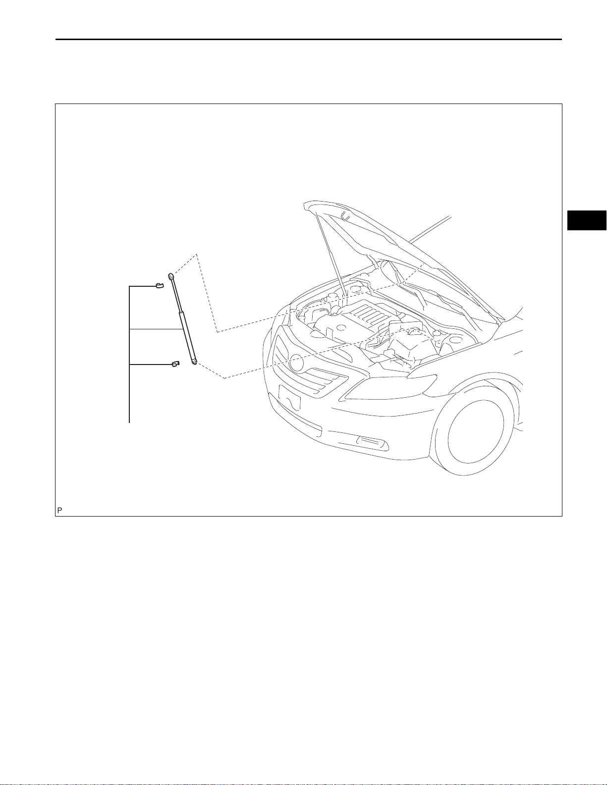
COMPONENTS
ED–3
ED
HOOD SUPPORT ASSEMBLY
B136842E01
ED
ED–4
ENGINE HOOD / DOOR – HOOD SUPPORT ROD
REMOVAL
NOTICE:
• Avoid touching the stroke portions of the rod as much
as possible to prevent foreign matter from att aching to
it. Be sure to hold the cylinders while servicing.
• Do not wear cotton gloves or other similar materials
when handling the rod. Fibers may attach to the rod
and result in gas leaks.
• Do not apply any load to the cylinders in the horizont al
direction in order to prevent the rod from being
deformed.
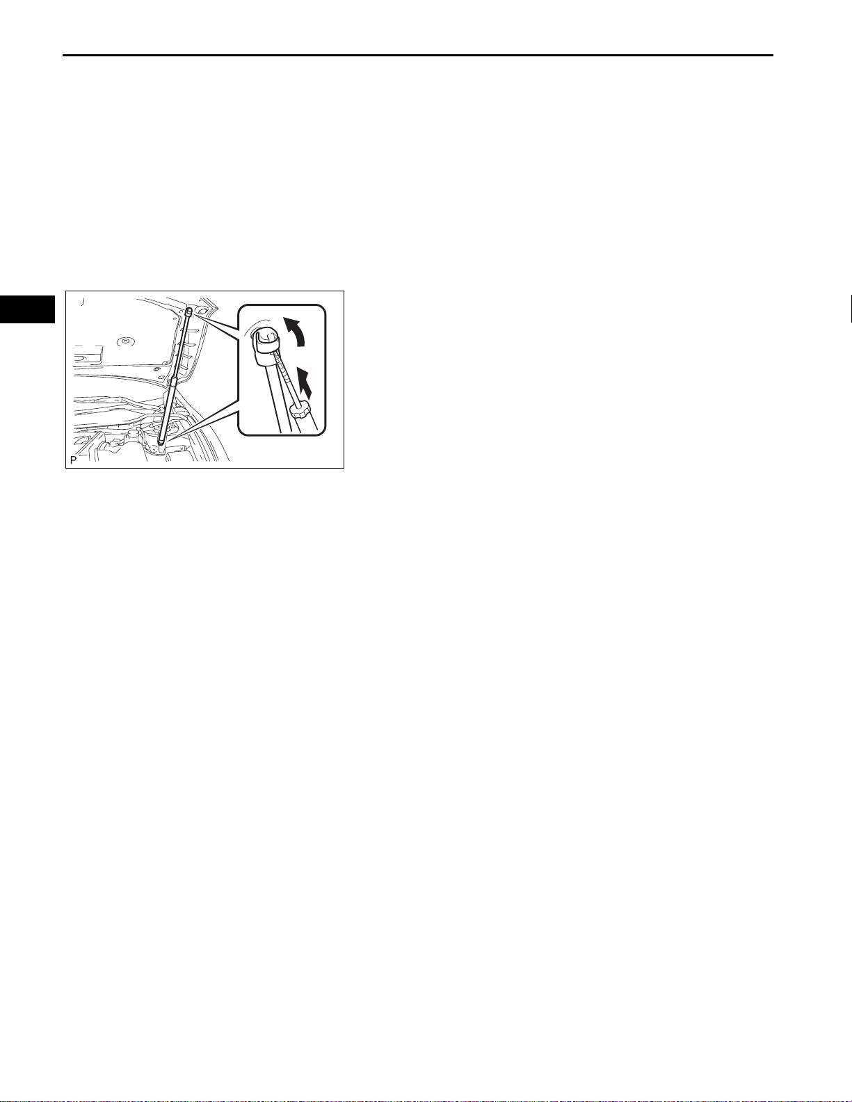
1. REMOVE HOOD SUPPORT ASSEMBLY
(a) Using a screwdriver, remove the hood support
assembly while releasing the 2 clips.
NOTICE:
Remove the hood support assembly while
supporting the hood with hand.
B132831
ENGINE HOOD / DOOR – HOOD SUPPORT ROD
INSTALLATION
NOTICE:
• Avoid touching the stroke portions of the rod as muc h
as possible to prevent foreign matter from attac hing to
it. Be sure to hold the cylinders while servicing.
• Do not wear cotton gloves or other similar materials
when handling the rod. Fibers may attach to the rod
and result in gas leaks.
• Do not apply any load to the cylinders in the horizontal
direction in order to prevent the rod from being
deformed.
1. INSTALL HOOD SUPPORT ASSEMBLY
(a) Install the hood support assembly.
NOTICE:
• Install the hood support assembly while
supporting the hood with hand.
• Check that the hood support assembly is
engaged in the ball joint and it cannot be
pulled out.
DISPOSAL
ED–5
ED
80 mm
A
(3.150 in.)
B
B127037E01
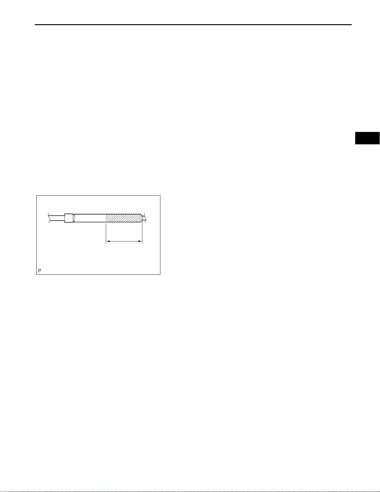
1. DISPOSE OF HOOD SUPPORT ASSEMBLY
(a) Horizontally fix the hood support in a vise with the
piston-rod pulled out.
(b) Wear safety glasses. Gradually cut a part between
A and B shown in the illustration using a metal saw
and gradually release the gas.
NOTICE:
Although the gas inside the hood support is
colorless, odorless and harmless, there is a
possibility that metal debris could scatter.
Therefore, cover it with a piece of cloth or other
material.
ENGINE HOOD / DOOR – HOOD LOCK CONTROL CABLE ASSEMBLY
BODYENGINE HOOD / DOOR
HOOD LOCK CONTROL CABLE ASSEMBLY
COMPONENTS
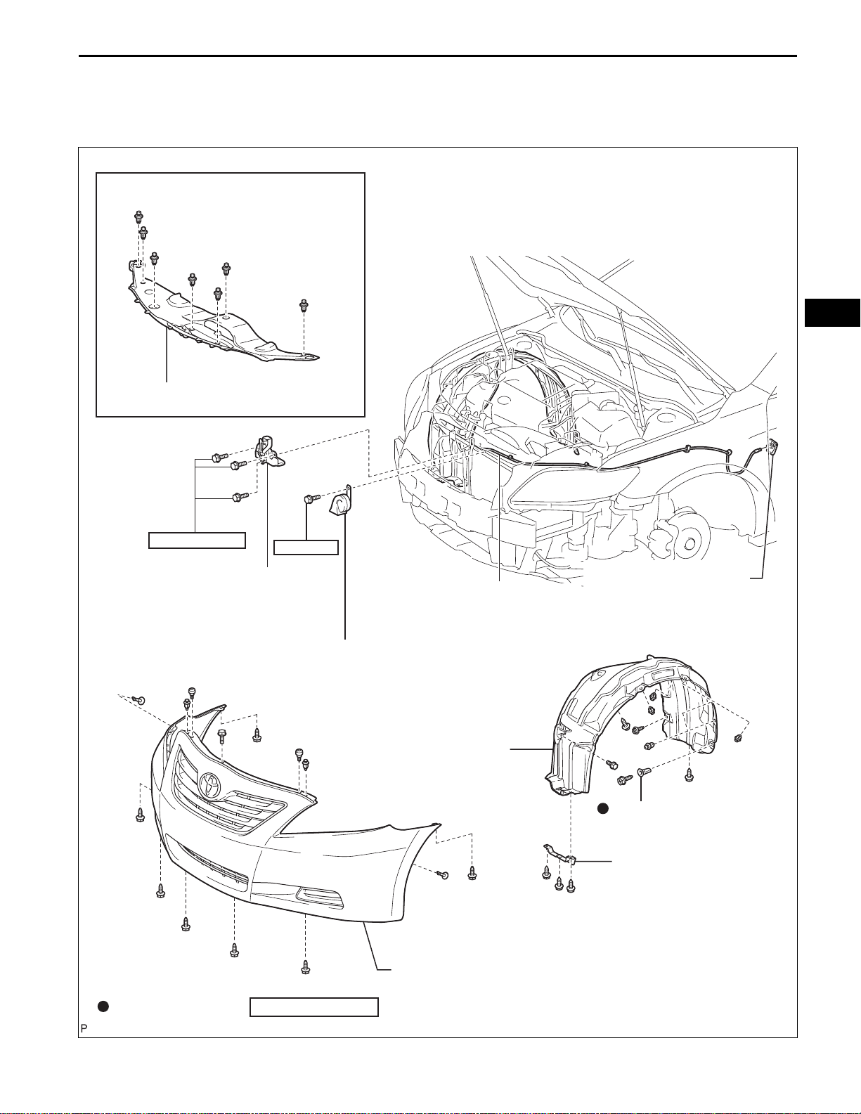
for 2GR-FE:
COOL AIR INTAKE DUCT SEAL
ED–5
ED
7.5 (77, 66 in.*lbf)
HOOD LOCK
ASSEMBLY
20 (204, 15)
HIGH PITCHED
HORN ASSEMBLY
FRONT FENDER LINER
HOOD LOCK CONTROL
CABLE ASSEMBLY
HOOD LOCK CONTROL
LEVER SUB-ASSEMBLY
GROMMET
FRONT WHEEL OPENING
EXTENSION PAD
Non-reusable part
N*m (kgf*cm, ft.*lbf)
FRONT BUMPER ASSEMBLY
: Specified torque
B136867E01
ED
ED–6
ENGINE HOOD / DOOR – HOOD LOCK CONTROL CABLE ASSEMBLY
REMOVAL
1. REMOVE FRONT WHEEL
2. REMOVE FRONT WHEEL OPENING EXTENSION
PAD
(a) Remove the 3 screws and the front wheel opening
extension pad.
3. REMOVE COOL AIR INTAKE DUCT SEAL (for 2GRFE) (See page ET-4)
4. REMOVE FRONT BUMPER ASSEMBLY (w/o Fog
Light) (See page ET-5)
B138883
5. REMOVE FRONT BUMPER ASSEMBLY (w/ Fog
Light) (See page ET-6)
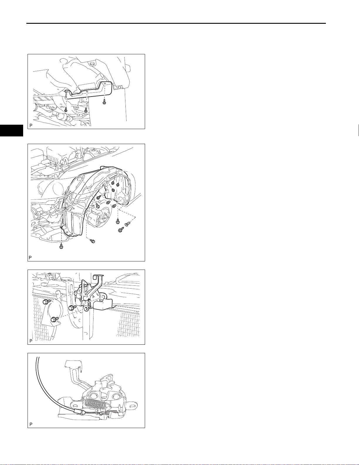
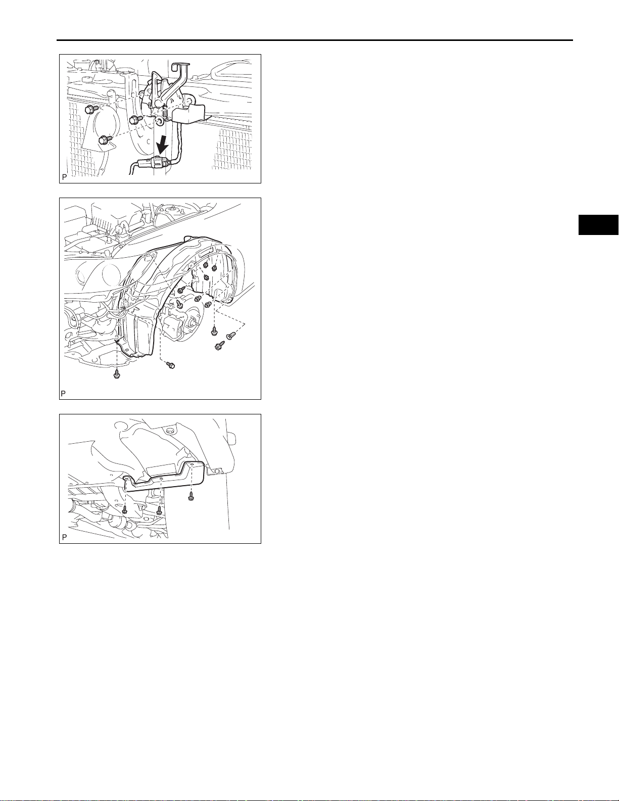
6. REMOVE FRONT FENDER LINER
(a) Remove the 5 clips and bolt.
(b) Remove the 4 screws, grommet and the front fender
liner.
7. REMOVE HIGH PITCHED HORN ASSEMBLY (See
page HO-7)
B136871
B136821
B136827
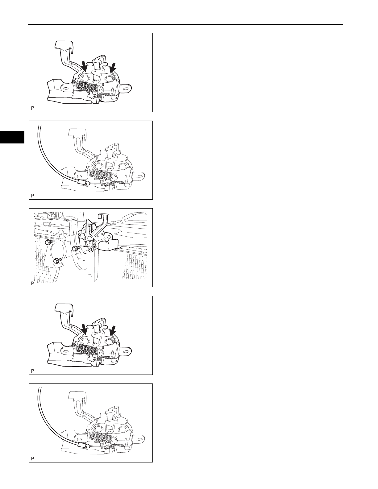
8. REMOVE HOOD LOCK ASSEMBL Y (w/o Engine Hood
Courtesy Switch)
(a) Remove the 3 bolts.
(b) Disconnect the hood lock control cable.
(c) Remove the hood lock assembly.
ENGINE HOOD / DOOR – HOOD LOCK CONTROL CABLE ASSEMBLY
9. REMOVE HOOD LOCK ASSEMBLY (w/ Engine Hood
Courtesy Switch)
(a) Disconnect the connector.
(b) Remove the 3 bolts.
B136822
(c) Disconnect the hood lock control cable.
(d) Remove the hood lock assembly.
B136827
ED–7
ED
10. REMOVE HOOD LOCK CONTROL LEVER SUBASSEMBLY
(a) Disconnect the hood lock control cable and remove
the hood lock control lever.
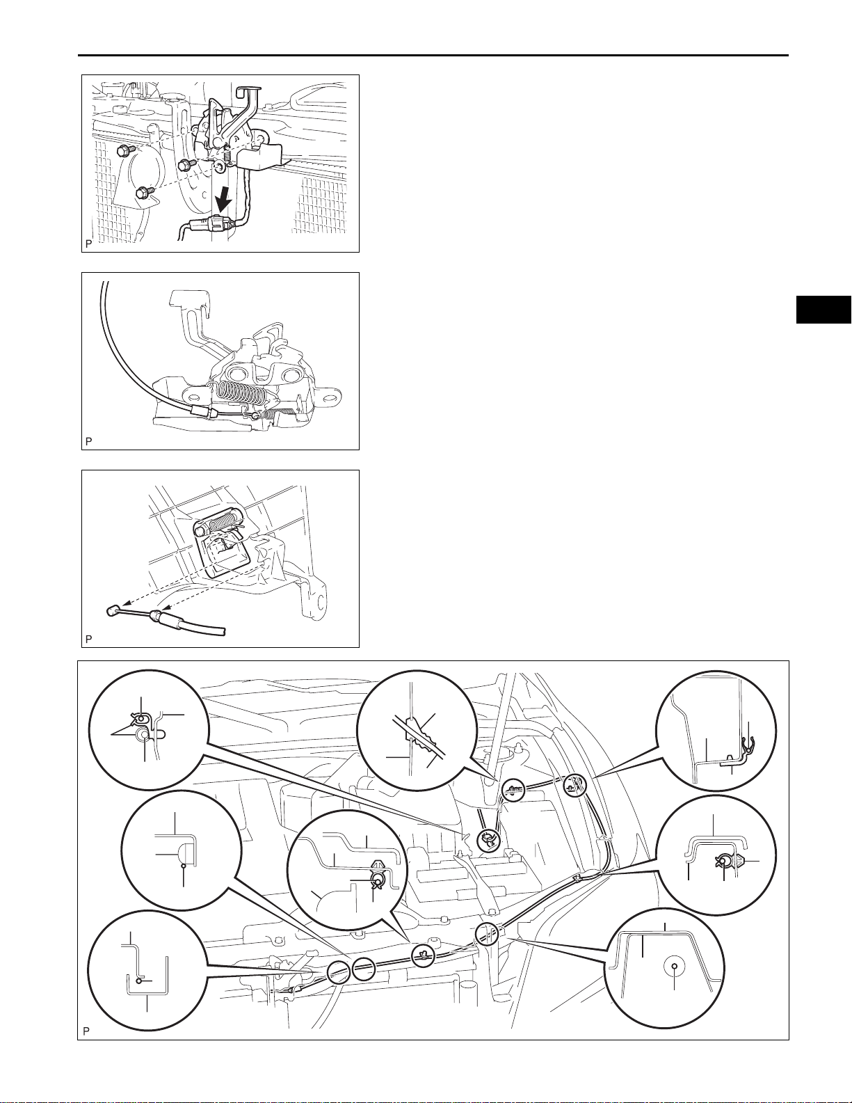
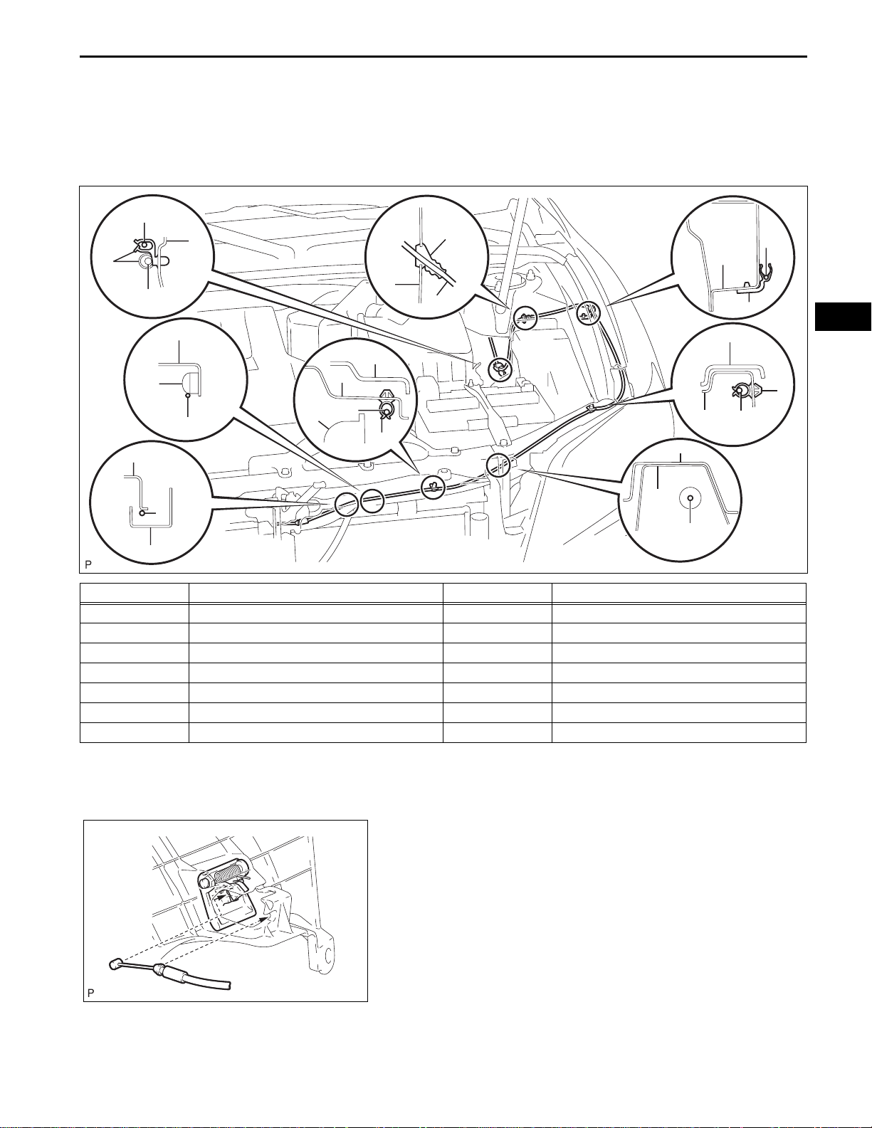
11. REMOVE HOOD LOCK CONTROL CABLE
ASSEMBLY
(a) Using a screwdriver, disconnect the clamps shown
in the illustration.
B136909
A
D
B
C
F
E
A
F
F
J
I
K
A
B
H
L
A
F
F
A
B
K
B
A
M
A
A
G
B136828E01

ED
ED–8
Area Part Name Area Part Name
A Hood lock control cable H Grommet
B Clamp I Side member outer
C Wire harness J Radiator
D Pillar K Radiator support cover
E Nut L Front fender apron
F Radiator support upper M Brace
G Hood lock protector - -
ENGINE HOOD / DOOR – HOOD LOCK CONTROL CABLE ASSEMBLY
HINT:
Tape the screwdriver tip before use.
(b) Pull the cable from the engine compartment and
remove it.
ENGINE HOOD / DOOR – HOOD LOCK CONTROL CABLE ASSEMBLY
ED–9
INSTALLATION
1. INSTALL HOOD LOCK CONTROL CABLE
ASSEMBLY
(a) Pass the hood lock control cable assembly into the
engine compartment.
A
D
B
C
I
H
L
A
A
B
ED
F
K
E
A
F
F
A
J
B
F
K
B
F
A
M
A
A
G
Area Part Name Area Part Name
A Hood lock control cable H Grommet
B Clamp I Side member outer
C Wire harness J Radiator
D Pillar K Radiator support cover
E Nut L Front fender apron
F Radiator support upper M Brace
G Hood lock protector - -
(b) Pass the cable front side through the upper radiator
support.
(c) Connect the clamps as shown in the illustration.
2. INSTALL HOOD LOCK CONTROL LEVER SUBASSEMBLY
(a) Install the hood lock control lever and connect the
hood lock control cable.
B136828E01
B136826
ED
ED–10
ENGINE HOOD / DOOR – HOOD LOCK CONTROL CABLE ASSEMBLY
3. INST ALL HOOD LOCK ASSEMBLY (w/o Engine Hood
Courtesy Switch)
(a) Apply MP grease to the sliding areas of the lock.
B136830
(b) Connect the hood lock control cable.
B136827
B136821
B136830
(c) Install the hood lock assembly with the 3 bolts.
Torque: 7.5 N*m (77 kgf*cm, 66 in.*lbf)
4. INSTALL HOOD LOCK ASSEMBLY (w/ Engine Hood
Courtesy Switch)
(a) Apply MP grease to the sliding areas of the lock.
(b) Connect the hood lock control cable.
B136827
ENGINE HOOD / DOOR – HOOD LOCK CONTROL CABLE ASSEMBLY
(c) Install the hood lock assembly with the 3 bolts.
Torque: 7.5 N*m (77 kgf*cm, 66 in.*lbf)
(d) Connect the connector.
5. INSTALL HIGH PITCHED HORN ASSEMBLY (See
page HO-7)
B136822
6. INSTALL FRONT FENDER LINER
(a) Install the front fender liner with the grommet and 4
screws.
(b) Install the bolt and 5 clips.
7. INSPECT HOOD SUB-ASSEMBLY (See page ED-1)
8. ADJUST HOOD SUB-ASSEMBLY (See page ED-2)
9. INSTALL FRONT BUMPER ASSEMBLY (w/o Fog
Light) (See page ET-13)
ED–11
ED
B136871
B138883
10. INST ALL FRONT BUMPER ASSEMBLY (w/ Fog Light)
(See page ET-14)
11. INSTALL COOL AIR INTAKE DUCT SEAL (for 2GRFE) (See page ET-14)
12. INSTALL FRONT WHEEL OPENING EXTENSION PAD
(a) Install the front wheel opening extension pad with
the 3 screws.
13. INSTALL FRONT WHEEL (See page SP-22)
14. VEHICLE PREPARATION FOR FOG LIGHT AIM (w/
Fog Light) (See page LI-79)
15. PREPARATION FOR FOG LIGHT AIMING (w/ Fog
Light) (See page LI-80)
16. FOG LIGHT AIMING INSPECTION (w/ Fog Light) (See
page LI-81)
17. FOG LIGHT AIMING ADJUSTMENT (w/ Fog Light)
(See page LI-82)
BODYENGINE HOOD / DOOR
FRONT DOOR
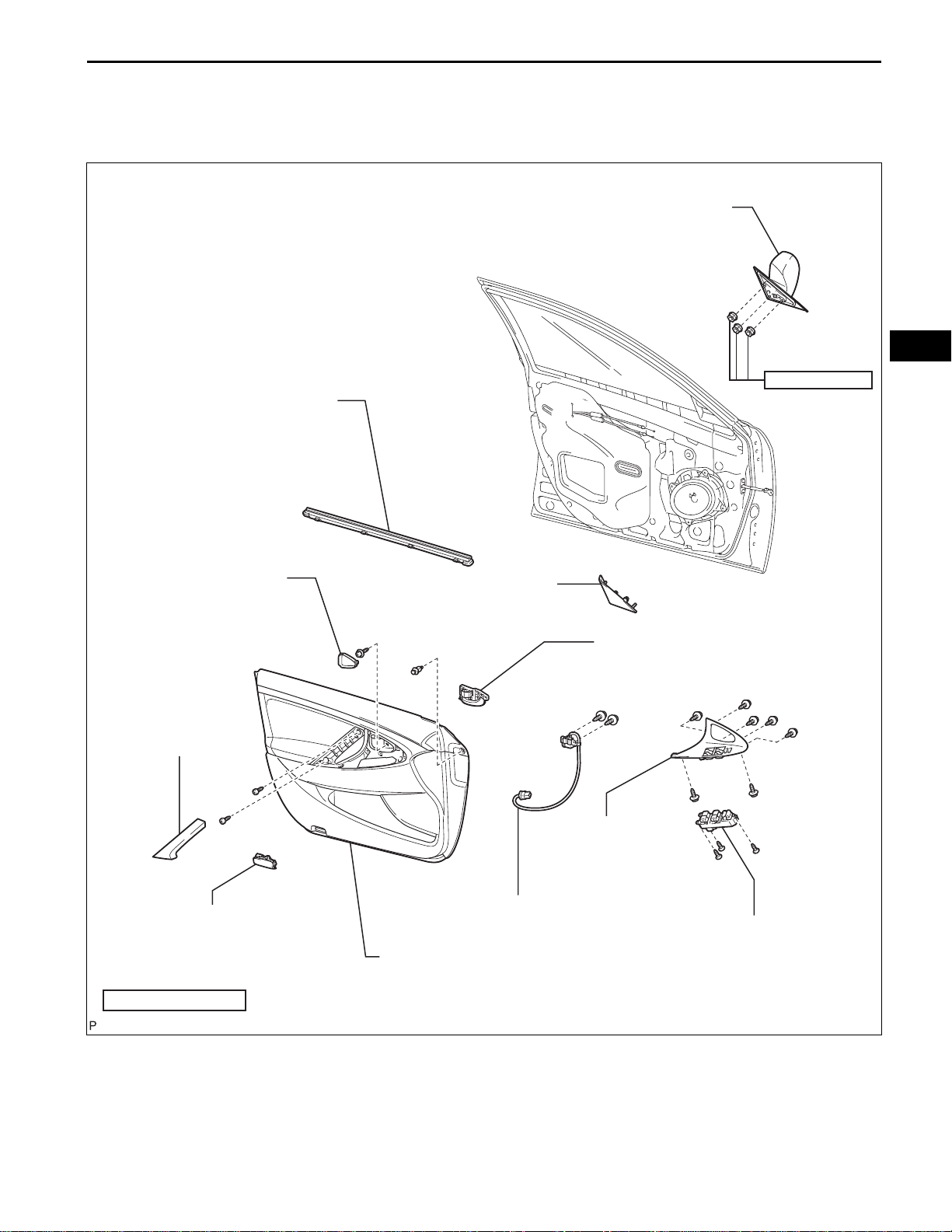
COMPONENTS
ENGINE HOOD / DOOR – FRONT DOOR
OUTER REAR VIEW MIRROR ASSEMBLY
ED–11
ED
FRONT DOOR INNER
GLASS WEATHERSTRIP
FRONT DOOR INSIDE
HANDLE BEZEL PLUG
ASSIST GRIP COVER
5.5 (56, 49 in.*lbf)
FRONT DOOR LOWER
FRAME BRACKET GARNISH
FRONT DOOR INSIDE
HANDLE SUB-ASSEMBLY
FRONT ARMREST
BASE PANEL UPPER
COURTESY LIGHT
ASSEMBLY
N*m (kgf*cm, ft.*lbf)
: Specified torque
FRONT DOOR WIRE
FRONT DOOR TRIM
BOARD SUB-ASSEMBLY
POWER WINDOW REGULATOR
MASTER SWITCH ASSEMBLY
B146077E01
ED–12
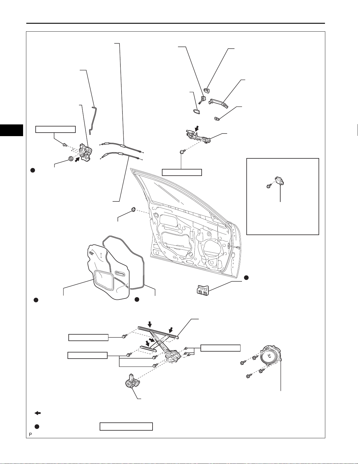
ENGINE HOOD / DOOR – FRONT DOOR
ED
FRONT DOOR LOCK REMOTE
CONTROL CABLE ASSEMBLY
FRONT DOOR
LOCK OPEN ROD
FRONT DOOR
LOCK ASSEMBLY
5.0 (51, 44 in.*lbf)
DOOR LOCK WIRING
HARNESS SEAL
FRONT DOOR INSIDE
LOCKING CABLE ASSEMBLY
FRONT DOOR
LOCK CYLINDER
FRONT DOOR REAR
OUTSIDE HANDLE PAD
4.0 (41, 35 in.*lbf)
FRONT DOOR OUTSIDE
HANDLE COVER
FRONT DOOR OUTSIDE
HANDLE ASSEMBLY
FRONT DOOR FRONT
OUTSIDE HANDLE PAD
FRONT DOOR OUTSIDE HANDLE
FRAME SUB-ASSEMBLY
with Smart Key System:
DOOR ELECTRICAL
KEY OSCILLATOR
FRONT DOOR SERVICE
HOLE COVER
5.5 (56, 49 in.*lbf)
8.0 (82, 71 in.*lbf)
HOLE PLUG
FRONT NO. 1 DOOR
STIFFENER CUSHION
BUTYL TAPE
FRONT DOOR WINDOW
REGULATOR SUB-ASSEMBLY
5.4 (55, 48 in.*lbf)
Apply MP grease
Non-reusable part
FRONT POWER WINDOW REGULATOR
MOTOR ASSEMBLY
N*m (kgf*cm, ft.*lbf)
FRONT NO. 1
SPEAKER ASSEMBLY
: Specified torque
B146078E01
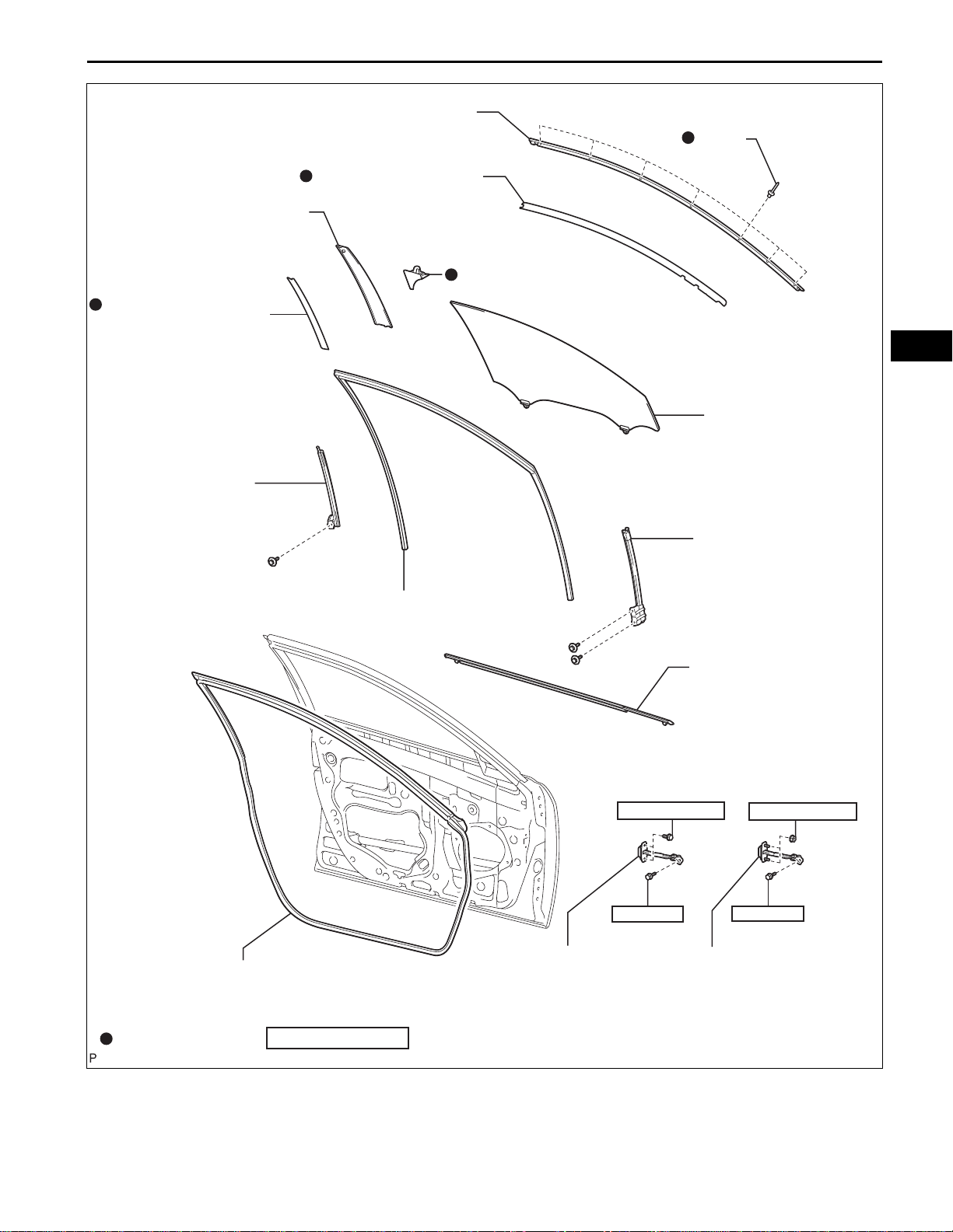
FRONT DOOR UPPER
WINDOW FRAME MOULDING
FRONT DOOR REAR
WINDOW FRAME MOULDING
FRONT DOOR LOWER
OUTSIDE STRIPE
FRONT DOOR REAR
LOWER FRAME
SUB-ASSEMBLY
ENGINE HOOD / DOOR – FRONT DOOR
FRONT DOOR STRIPE
DOOR FRAME GARNISH
ED–13
RIVET
ED
FRONT DOOR GLASS
SUB-ASSEMBLY
FRONT DOOR FRONT
LOWER FRAME
SUB-ASSEMBLY
FRONT DOOR WEATHERSTRIP
Non-reusable part
N*m (kgf*cm, ft.*lbf)
FRONT DOOR GLASS RUN
: Specified torque
TMC made:
8.0 (82, 71 in.*lbf)
26 (265, 19)
FRONT DOOR
CHECK ASSEMBLY
FRONT DOOR BELT
MOULDING ASSEMBLY
TMMK made:
8.0 (82, 71 in.*lbf)
26 (265, 19)
FRONT DOOR
CHECK ASSEMBLY
B146081E01
ED–14
ENGINE HOOD / DOOR – FRONT DOOR
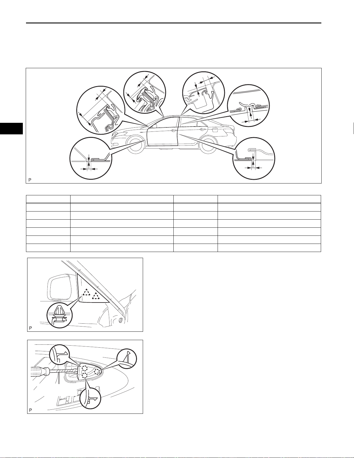
ON-VEHICLE INSPECTION
1. INSPECT FRONT DOOR PANEL SUB-ASSEMBLY
(a) Check that the clearance measurements of areas A
to L are within each standard range.
ED
E
C
F
D
B
A
H
G
J
I
L
K
Standard clearance
Area Measurement Area Measurement
A 2.7 to 5.7 mm (0.106 to 0.224 in.) G 3.3 to 6.3 mm (0.130 to 0.248 in.)
B -1.5 to 1.5 mm (-0.059 to 0.059 in.) H -0.3 to 2.7 mm (-0.012 to 0.106 in.)
C 3.3 to 6.3 mm (0.130 to 0.248 in.) I 2.3 to 6.3 mm (0.091 to 0.248 in.)
D 6.4 to 9.4 mm (0.252 to 0.370 in.) J -2.0 to 2.0 mm (-0.079 to 0.079 in.)
E 3.3 to 6.3 mm (0.130 to 0.248 in.) K 2.7 to 5.7 mm (0.106 to 0.224 in.)
F 0.9 to 3.9 mm (0.035 to 0.154 in.) L -1.5 to 1.5 mm (-0.059 to 0.059 in.)
B132823E01
Protective tape
DISASSEMBLY
1. REMOVE FRONT DOOR LOWER FRAME BRACKET
GARNISH
(a) Disengage the 2 clips and remove the front door
lower frame bracket garnish.
B132833
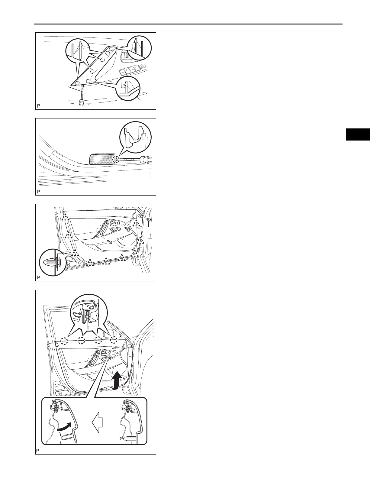
2. REMOVE FRONT DOOR INSIDE HANDLE BEZEL
PLUG
(a) Using a screwdriver wrapped with protective tape,
disengage the 3 claws, and remove the front door
inside handle bezel plug.
B132834E01
Protective
tape
ENGINE HOOD / DOOR – FRONT DOOR
B132836E01
Protective tape
B132838E01
3. REMOVE ASSIST GRIP COVER
(a) Using a screwdriver wrapped with protective tape,
disengage the 6 claws and remove the assist grip
cover.
4. REMOVE COURTESY LIGHT ASSEMBLY
(a) Using a screwdriver wrapped with protective tape,
disengage the claw and remove the courtesy light
assembly.
(b) Disconnect the connector.
ED–15
ED
(A)
B132840E01
5. REMOVE FRONT DOOR TRIM BOARD SUBASSEMBLY
(a) Remove the 3 screws and clip (A).
(b) Using the clip remover, disengage the 9 clips.
(c) Pull out the front door trim board in the direction
indicated by the arrow.
(d) Remove the reference bosses from the front door
panel.
(e) Raise the front door trim board to disengage the 4
claws and remove the front door trim board together
with the front door inner glass weatherstrip.
Reference Boss
B136401E01
ED
ED–16
ENGINE HOOD / DOOR – FRONT DOOR
(f) Disengage the 2 claws and disconnect the front
door inside handle sub-assembly.
B136403
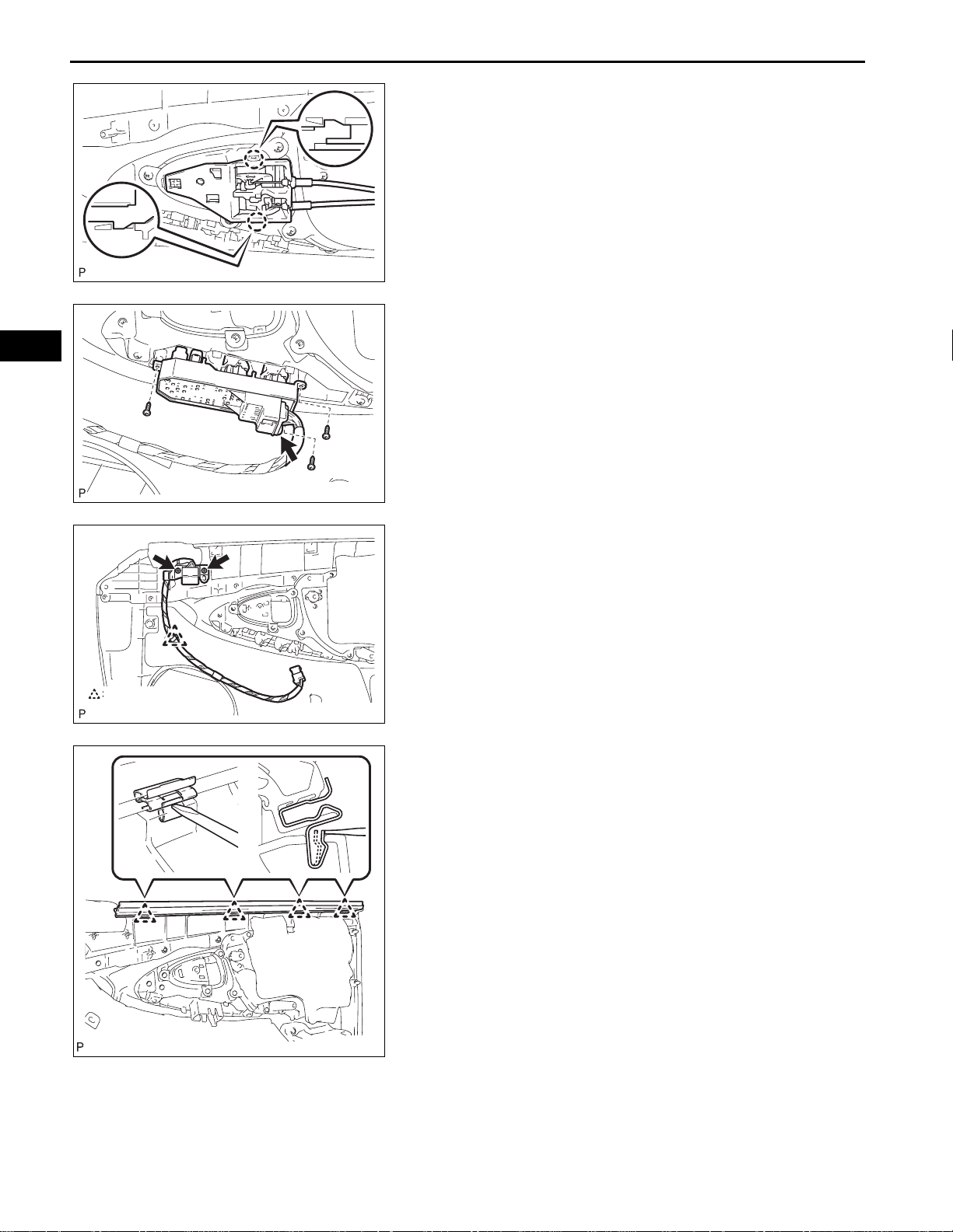
6. REMOVE POWER WINDOW REGULATOR MASTER
SWITCH ASSEMBLY
(a) Disconnect the connector.
(b) Remove the 3 screws and the power window
regulator master switch assembly.
B136405
Clamp
7. REMOVE FRONT DOOR WIRE (for Driver Side)
(a) Disengage the clamp and remove the 2 screws and
front door wire.
B136406E01
8. REMOVE FRONT DOOR INNER GLASS
WEATHERSTRIP
(a) Using a screwdriver, disengage the 4 clip s as shown
in the illustration and remove the front door inner
glass weatherstrip from the front door trim board.
B136404
ENGINE HOOD / DOOR – FRONT DOOR
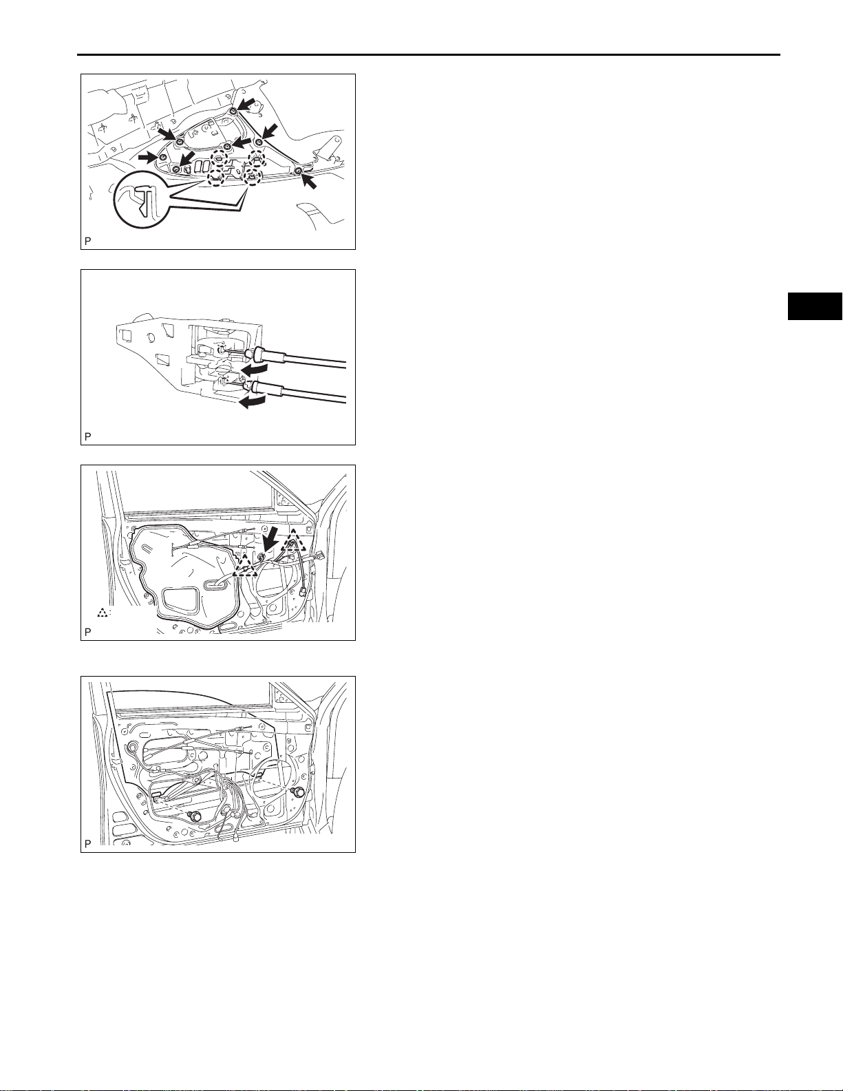
9. REMOVE FRONT ARMREST BASE PANEL UPPER
(a) Remove the 7 screws.
(b) Disengage the 4 claws and remove the front
armrest base panel upper.
B136407
10. REMOVE FRONT DOOR INSIDE HANDLE SUBASSEMBLY
(a) Disconnect the front door lock remote control cable
and front door inside locking cable and remove the
front door inside handle sub-assembly.
11. REMOVE FRONT NO. 1 SPEAKER ASSEMBLY (See
page AV-155)
12. REMOVE OUTER REAR VIEW MIRROR ASSEMBLY
B136408
(See page MI-15)
ED–17
ED
Clamp
B146069E01
B136412
13. REMOVE FRONT DOOR SERVICE HOLE COVER
(a) Disconnect the connector and each clamp, and
remove the front door service hole cover.
HINT:
Remove the remaining butyl tape on the door side.
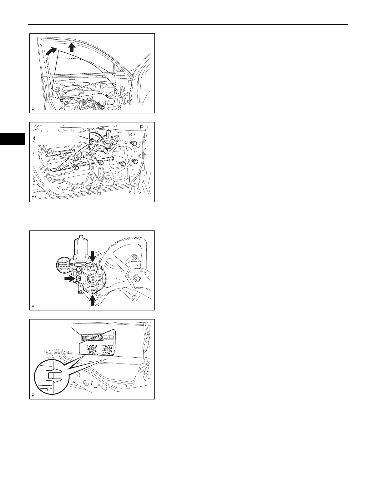
14. REMOVE FRONT DOOR GLASS SUB-ASSEMBLY
(a) Connect the front power window regulator motor
assembly connector.
(b) Connect the power window regulator master switch
assembly and move the front door glass subassembly so that the door glass bolts can be seen.
(c) Remove the 2 bolts.
NOTICE:
After the bolts are removed, the door glass may
fall and become deformed.
ED
ED–18
(1)
Temporary Bolt
(2)
ENGINE HOOD / DOOR – FRONT DOOR
(d) Remove the front door glass sub-assembly as
shown in the illustration.
NOTICE:
Do not damage the door glass.
(e) Disconnect the power window regulator master
switch assembly and front power window regulator
motor assembly connector.
B136413E01
15. REMOVE FRONT DOOR WINDOW REGULATOR
SUB-ASSEMBLY
(a) Loosen the temporary bolt.
NOTICE:
If the temporary bolt is removed, the front door
window regulator may fall and become
deformed.
(b) Remove the 5 bolts.
(c) Remove the front door window regulator sub-
B136415E01
assembly and the power window regulator motor
assembly front as a unit.
(d) Remove the temporary bolt from the front door
window regulator sub-assembly.
Double-sided
Ta pe
16. REMOVE FRONT POWER WINDOW REGULATOR
MOTOR ASSEMBLY
(a) Using a "torx" driver (T25), remove the 3 screws
and the front power window regulator motor
assembly.
B136416
17. REMOVE FRONT NO. 1 DOOR STIFFENER CUSHION
(a) Disengage the 2 claws.
(b) Remove the double-sided tape and the front No. 1
door stiffener cushion.
B136417E01
ENGINE HOOD / DOOR – FRONT DOOR
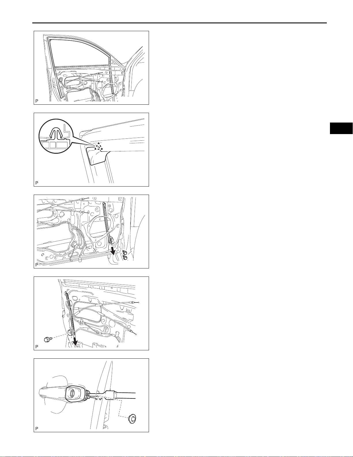
18. REMOVE FRONT DOOR GLASS RUN
(a) Remove the front door glass run.
B136418
19. REMOVE DOOR FRAME GARNISH
(a) Disengage the clip and remove the door frame
garnish.
B136435
ED–19
ED
B136419E01
B136420E01
B136421
20. REMOVE FRONT DOOR FRONT LOWER FRAME
SUB-ASSEMBLY
(a) Remove the 2 bolts and the front door front lower
frame sub-assembly as shown in the illustration.
21. REMOVE FRONT DOOR REAR LOWER FRAME SUBASSEMBLY
(a) Remove the bolt and the front door rear lower frame
sub-assembly as shown in the illustration.
22. REMOVE FRONT DOOR OUTSIDE HANDLE COVER
(a) Remove the hole plug.
(b) Using a "torx" socket wrench (T30), loosen the
screw and remove the front door outside handle
cover and the door lock key cylinder as a unit.
HINT:
The screw cannot be removed because it is
integrated into the front door outside handle frame
sub-assembly.
ED
ED–20
ENGINE HOOD / DOOR – FRONT DOOR
(c) Using a screwdriver, disengage the 2 claws and
remove the front door outside handle cover.
B136424
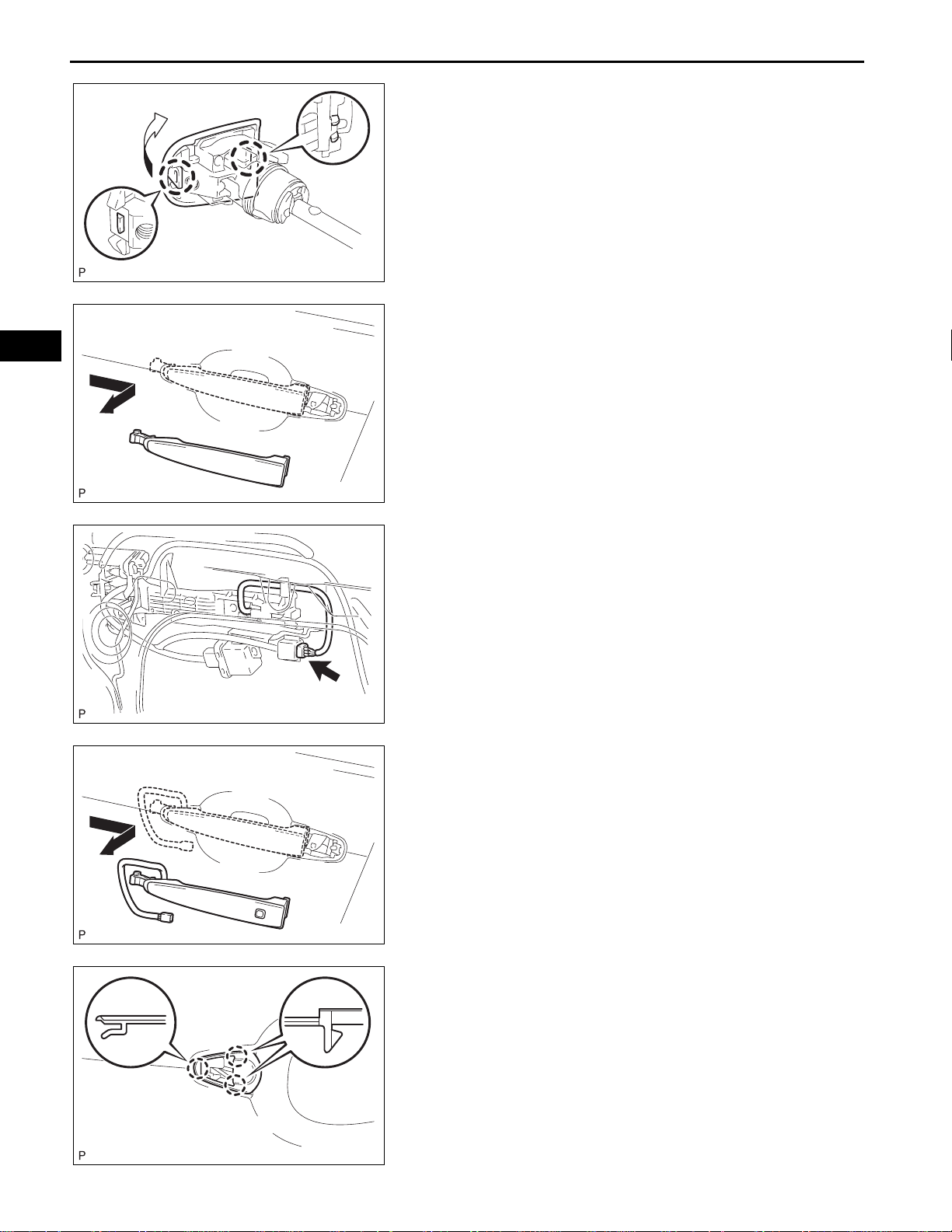
23. REMOVE FRONT DOOR OUTSIDE HANDLE
ASSEMBLY (w/o Smart Key System)
(a) Remove the front door outside handle assembly as
shown in the illustration.
B136858
B136857
B136422
24. REMOVE FRONT DOOR OUTSIDE HANDLE
ASSEMBLY (w/ Smart Key System)
(a) Disconnect the connector.
(b) Remove the front door outside handle assembly as
shown in the illustration.
25. REMOVE FRONT DOOR FRONT OUTSIDE HANDLE
PAD
(a) Disengage the 3 claws and remove the front door
front outside handle pad.
B136426
 Loading...