

Toyota Camry 2007-2009 Service Manual - Tire_and_Wheel

TIRE AND WHEEL – TIRE AND WHEEL SYSTEM
TIRE AND WHEEL SYSTEM
PRECAUTION
1. REMOVAL AND INSTALLATION OF THE TIRE
PRESSURE WARNING VALVE SUB-ASSEMBLY
(a) When installing a tire, make sure that the tire
pressure warning valve sub-assembly does not
interfere with the tire bead in order to prevent
damage to the tire pressure warning valve subassembly.
(b) After completing the operation, remove the valve
core to rapidly release the air in the tire and check
that the warning light comes on. If the warning light
does not come on, the system may be defective.
(c) If there is air leakage, tighten the nut to a torque of
4.0 N*m (41 kgf*cm, 35 in.*lbf) and push the valve
core 2 or 3 times to remove any dirt attached to the
valve core. If air continues to leak, replace the
grommet, washer, and nut.
(d) When installing the tire pressure warning valve sub-
assembly , check whether the rim, grommet, washer,
and nut are clean. Use a manufacturer-specified
cap.
(e) When putting air into the tire, first install the tire
pressure valve straight onto the stem of the tire
pressure warning valve sub-assembly.
2. TIRE AND WHEEL REPLACEMENT
(a) If replacing a tire, be sure to check the grommet of
the tire valve for damage. If the grommet is
damaged, replace the grommet, washer, and the
nut.
(b) If tires and wheels are replaced, register the
transmitter ID (see page TW-15).
TW–1
TW

TW–2
TIRE AND WHEEL – TIRE AND WHEEL SYSTEM
HOW TO PROCEED WITH
TROUBLESHOOTING
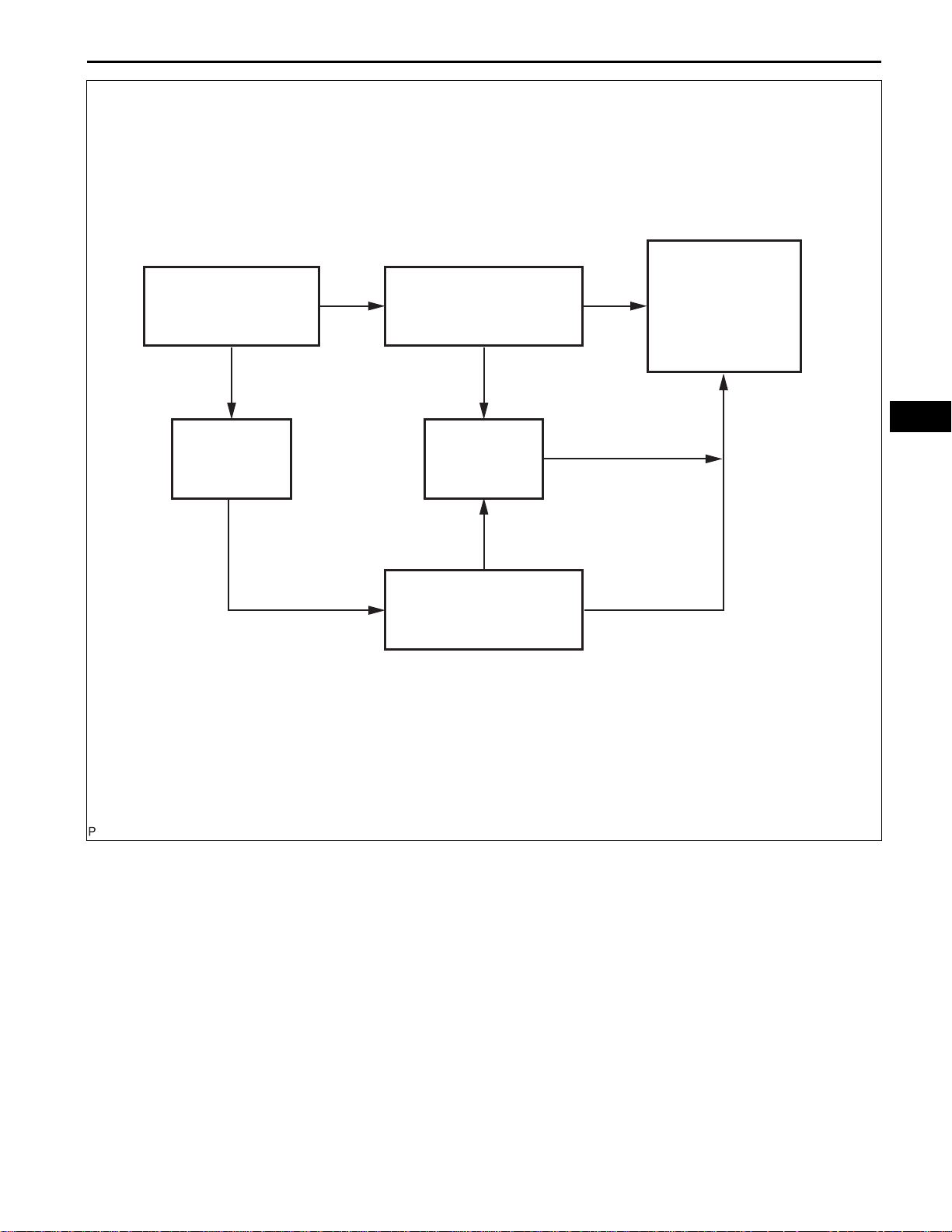
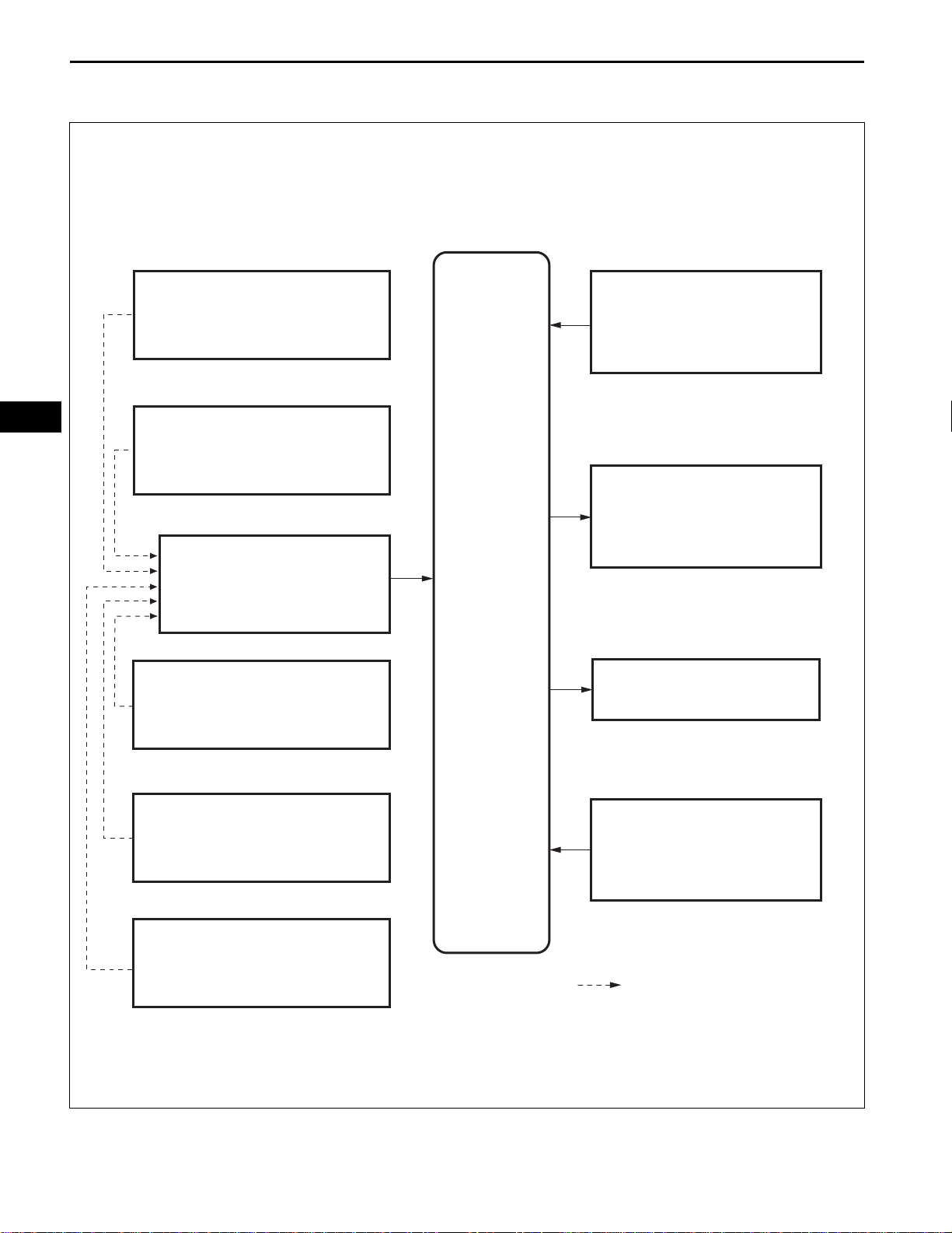
1. DIAGNOSIS OF TIRE VIBRATION
(a) Inspection procedure
TW
Check that the wheel
nuts are fully tightened.
OK
Check tire pressure.
NG
NG
OK
Repair
Check wheel balance.
NG
NG
Inspect bearing looseness.
Inspect axle hub runout.
OK
Repair tire(s).
OK
Return the vehicle
to the customer.
OK
Adjustment
Adjustment
NG
Check wheel balance.
2. DIAGNOSIS OF IRREGULAR TIRE WEAR
(a) Inspection procedure
Inspect bearing looseness.
Inspect axle hub runout.
OK
NG
Repair
C107882E08
TIRE AND WHEEL – TIRE AND WHEEL SYSTEM
TW–3
Check tire pressure.
NG
Adjustment Adjustment
OK
Check wheel alignment.
Check wheel alignment.
NG
NG
OK
Rotate or replace
the tire(s).
TW
OK
C107883E01

TW
TW–4
TIRE AND WHEEL – TIRE AND WHEEL SYSTEM
INSPECTION
1. INSPECT TIRE
(a) Check the tires for wear and proper inflation
pressure.
Cold tire inflation pressure
Tire size
P215/60R16 94V 210 (2.1, 31) 210 (2.1, 31)
P215/55R17 93V 220 (2.2, 32) 220 (2.2, 32)
Front kPa (kgf*cm
(b) Using a dial indicator, check the runout of the tires.
2
, psi) Rear kPa (kgf*cm2, psi)
When driving under the above vehicle conditions at
sustained high speeds above 160 km/h (100 mph),
in countries where such speeds are permitted bylaw, inflate the front and rear tires to 240 kPa (2.4
2
kgf*cm
, 35 psi) provided that it does not exceed the
maximum cold tire inflation pressure molded on the
tire sidewall.
Tire runout:
1.4 mm (0.055 in.) or less
Front
(A)
(B)
C137874
2. ROTATE TIRE
(a) Rotate the tires as shown in illustration (A). If the
vehicle is equipped with a grand spare tire, rotate
the tires as shown in illustration (B).
C135236E01
3. INSPECT WHEEL BALANCE
(a) Check and adjust the off-the-car balance.
(b) Steel wheel
(1) If necessary, check and adjust the on-the-car
balance.
Imbalance after adjustment:
8.0 g (0.018 lb.) or less.
C080976
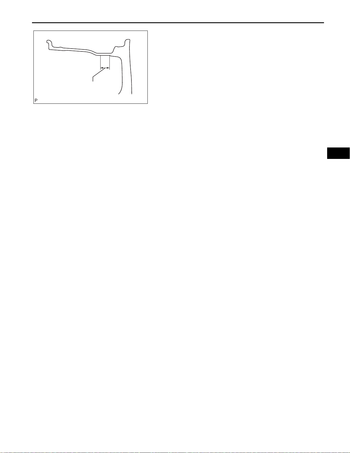
TIRE AND WHEEL – TIRE AND WHEEL SYSTEM
Approximately 25 mm (0.984 in.)
C110354E03
(c) Except for steel wheel
(1) If necessary, check and adjust the on-the-car
balance.
Imbalance after adjustment:
8.0 g (0.018 lb.) or less.
NOTICE:
• Remove dirt, oil and water from the
surface where the balance weight is to be
adhered with a cleaning detergent.
• Do not touch the sticking surface of the
tape.
• Adhere the sticking type balance weight
to the flat position shown in the
illustration.
• Push the balance weight securely with a
finger to adhere it to the position.
• Do not reuse the balance weight.
HINT:
The inner side balance weight should be
installed by clipping it to the rim.
TW–5
TW
4. INSPECT BEARING LOOSENESS
(See page AH-5 for FRONT AXLE, AH-15 for REAR
AXLE)
5. INSPECT AXLE HUB RUNOUT
(See page AH-6 for FRONT AXLE, AH-15 for REAR
AXLE)

TW
TW–6
Expression
Cold tire inflation pressure
P215/60R16 94W
P215/55R17 93V
Switch Type Ignition Switch (position) Engine Switch (condition)
Tire Pressure
Warning Light
Tire size
TIRE AND WHEEL – TIRE PRESSURE WARNING SYSTEM
TIRE PRESSURE WARNING
SYSTEM
PRECAUTION
1. EXPRESSIONS OF IGNITION SWITCH
(a) The type of ignition switch used on this model differs
according to the specification of the valves
Ignition switch off LOCK Off
Ignition switch on (IG) ON On (IG)
Ignition switch on (ACC) ACC On (ACC)
Engine start START Start
2. TIRE PRESSURE WARNING SYSTEM PRECAUTION
(a) When the tire pressure warning light comes on,
immediately check the tire pressure of the tire and
adjust it to the specified value. (The tire pressure
warning light will blink (come on after blinking for 1
minute) if there is an open in the tire pressure
warning light circuit.)
NOTICE:
Check the ground spare tire as well since this
E129450E01
210 (2.1, 31)
220 (2.2, 32)
Front kPa (kgf/cm
*1
240 (2.4, 35)
*1
240 (2.4, 35)
system monitors pressure of all tires including
the ground spare tire.
2
, psi) Rear kPa (kgf/cm2, psi)
*2
*2
210 (2.1, 31) *1 240 (2.4, 35)
220 (2.2, 32) *1 240 (2.4, 35)
*2
*2
*1: For driving under 100 mph (160 km/h)
*2: For driving at 100 mph (160 km/h) or over
(b) When the tire pressure warning light blinks (comes
on after blinking for 1 minute), there is a malfunction
in the system. Check for DTCs.
(c) It is necessary to register the transmitter ID in the
tire pressure warning ECU after replacing the tire
pressure warning valve and transmitter and/or tire
pressure warning ECU (See page TW-15).
(d) When replacing the tire pressure warning ECU;
(1) Using the DATA LIST, read the transmitter IDs
registered in the ECU and make a note of them
before removing the tire pressure warning ECU.
(2) Register the transmitter IDs after installing a new
tire pressure warning ECU.
TIRE AND WHEEL – TIRE PRESSURE WARNING SYSTEM
Tire pressure warning valve and transmitter:
TW–7
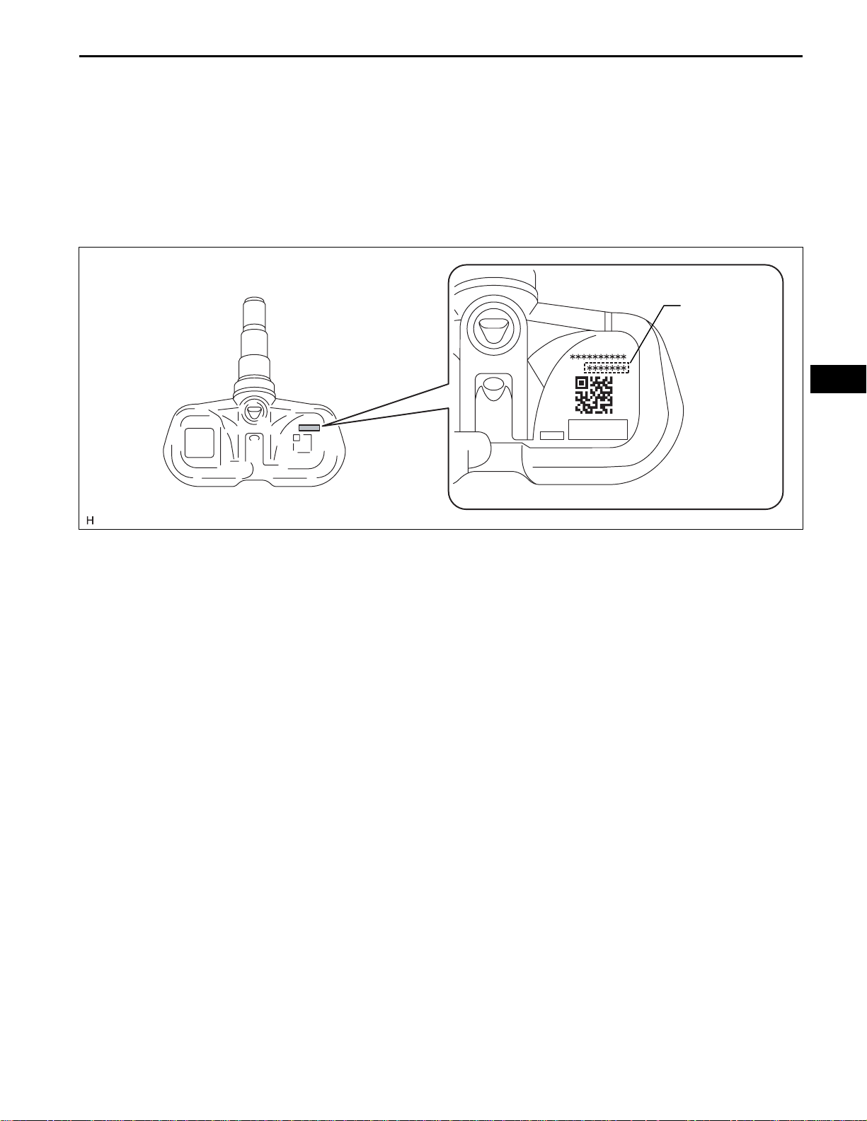
(e) When replacing the tire pressure warning valve and
transmitter;
(1) Take a note of the 7 digit number (transmitter ID)
written on the tire pressure warning valve and
transmitter when replacing it. Register the
transmitter IDs in the tire pressure warning ECU
after replacing the tire pressure warning valve
and transmitter and installing the tires and
wheels on the vehicle.
Transmitter ID
(7 digit number)
TW
NOTICE:
The transmitter ID is written on the tire
pressure warning valve and transmitter. It
will be unable to be read after installing the
tire pressure warning valve and transmitter
on the tire and wheel. Therefore, take a note
of the transmitter ID before installing the tire
pressure warning valve and transmitter.
(f) When replacing the tire pressure warning ECU and
the tire pressure warning valves and transmitters; It
is necessary to perform the initialization (See page
TW-18) after the registration (See page TW-15).
(g) Precautions about the tire pressure;
• The tire pressures decrease naturally.
• In winter, tire pressure may decrease due to low
ambient temperatures (tire pressure decreases
by approximately 10 kPa (0.2 kgf/cm
2
, 1.45 psi)
for every 10°C (50°F) drop in the ambient
temperature). Therefore, the tire pressure
warning is more likely to operate if the tire
pressures are not adjusted appropriately. If the
daily temperature variation is large, pressurize
the tires high so that the tire pressures are
suitable under cold conditions. Incorrect tire
pressure warning operation becomes less likely.
3. IN CASE OF TIRE AND WHEEL REPLACEMENT
(a) When tires and wheels are replaced, always ensure
that each transmitter ID is correctly registered.
E128762E02

TW
TW–8
TIRE AND WHEEL – TIRE PRESSURE WARNING SYSTEM
4. IN CASE OF REPLACEMENT OF TIRE PRESSURE
WARNING ECU, TIRE PRESSURE WARNING VALVE
AND TRANSMITTER, OR TIRE(S) WITH DIFFERENT
TIRE PRESSURE
(a) Initialize the tire pressure warning system after any
of the following is performed:
• Replacing the tire pressure warning ECU or the
tire pressure warning valve and transmitter
• Installing tire(s) which require different tire
pressure
HINT:
The tire pressure warning system will not operate
properly if it is not initialized (See page TW-18).
5. FAIL-SAFE FUNCTION
(a) When a system malfunction occurs in the tire
pressure warning system, the tire pressure warning
light blinks (comes on after blinking for 1 minute)
and informs the driver of the system failure.
(b) The result of this diagnosis is stored in the tire
pressure warning ECU.
TIRE AND WHEEL – TIRE PRESSURE WARNING SYSTEM
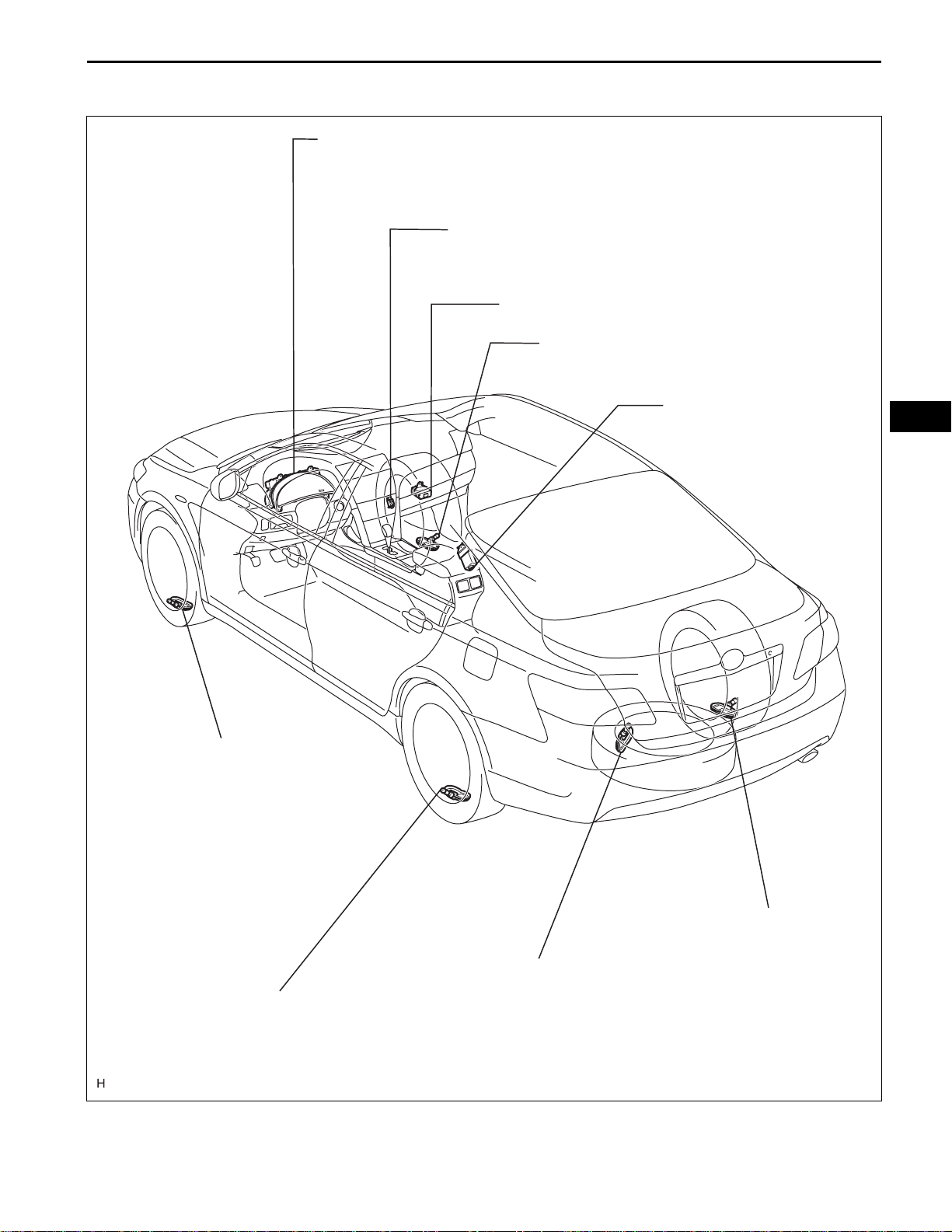
PARTS LOCATION
COMBINATION METER ASSEMBLY
- TIRE PRESSURE WARNING LIGHT
TIRE PRESSURE WARNING
RESET SWITCH
TIRE PRESSURE WARNING ECU
TIRE PRESSURE WARNING
VALVE AND TRANSMITTER
TW–9
TIRE PRESSURE WARNING
ANTENNA AND RECEIVER
TW
TIRE PRESSURE WARNING
VALVE AND TRANSMITTER
TIRE PRESSURE WARNING
VALVE AND TRANSMITTER
TIRE PRESSURE WARNING
VALVE AND TRANSMITTER
TIRE PRESSURE WARNING
VALVE AND TRANSMITTER (*)
*1: GROUND SPARE TIRE
E129453E01
TW–10
TIRE AND WHEEL – TIRE PRESSURE WARNING SYSTEM
SYSTEM DIAGRAM
TW
Front Tire Pressure Warning Valve
and Transmitter LH
Front Tire Pressure Warning Valve
and Transmitter RH
Tire Pressure Warning Antenna
and Receiver
Rear Tire Pressure Warning Valve
and Transmitter LH
Combination Meter
(Vehicle Speed Signal)
Combination Meter (Tire
Pressure Warning Light)
Tire Pressure
Warning ECU
DLC3
Rear Tire Pressure Warning Valve
and Transmitter RH
Tire Pressure Warning Valve and
Transmitter (Spare Tire) (*)
Tire Pressure Warning
Reset Switch
:
Radio Signal
*: Ground Spare Tire
C138248E01

TIRE AND WHEEL – TIRE PRESSURE WARNING SYSTEM
SYSTEM DESCRIPTION
1. DESCRIPTION OF SYSTEM
(a) A tire pressure warning valve and transmitter is
equipped with a tire pressure sensor and a
transmitter and is installed in a tire wheel assembly.
The sensor measures the tire pressure. The
measured value and transmitter ID are transmitted
to the tire pressure warning antenna and receiver on
the body as radio waves and then sent to the tire
pressure warning ECU from the tire pressure
warning antenna and receiver. If the transmitter ID
has already been registered, the ECU compares the
measured air pressure value with the standard
value. When the value is less than the standard
value registered in the tire pressure monitor ECU,
the warning light on the combination meter comes
on.
• For the differences in the air pressure settings by
the type of tires, a tire pressure warning reset
switch has been adopted.
TW–11
TW
Combination Meter Assembly
- Tire Pressure Warning Light
Tire Pressure
Warning Reset
Switch
Front
Tire Pressure Warning ECU
Tire Pressure Warning Valve and Transmitter
Tire Pressure Warning Valve and Transmitter
2. WHEN TIRE PRESSURE WARNING LIGHT IS LIT
(a) When the tire pressure warning light does not go off,
or when it comes on during driving, check tire
pressure. If the tire pressure warning light comes on
within several hours after adjusting the tire
pressure, the tire may have a slow air leak.
(b) Under the following conditions, the system may not
function properly.
• Facilities or devices that use similar radio
frequencies are located in the vicinity of the
vehicle.
Tire Pressure Warning
Antenna and Receiver
Tire Pressure
Warning Valve and
Transmitter (*)
*: Ground Spare Tire
E129451E02

TW
TW–12
TIRE AND WHEEL – TIRE PRESSURE WARNING SYSTEM
• A radio device of similar frequency is used in the
vehicle.
• A large amount of snow or ice is stuck to the
vehicle, especially onto the wheels and around
the wheel houses.
• The battery of the sensor has been depleted.
• The tires without tire pressure warning valve and
transmitter are used.
• Tire chains are used.
• When the ground spare tire is not within the
receivable range of the electric wave, a signal
may not be received because the ground spare
tire is fixed. Accordingly, the system may not
function properly. If there is a possibility that the
tire pressure warning system does not receive a
signal from the grounde spare tire, rotate the tire
90°.
• If any wheels other than the specified ones are
used, the system may not function properly
because interference may prevent the radio
waves from being correctly transmitted from the
tire pressure sensor.
• Depending on the tire type, the system may not
function properly even though the specified
wheels are used.
(c) The average usage life of the grommet of the tire
pressure warning valve and transmitter is
approximately 5 years, at which time it must be
replaced.
Re-tighten the valve nut if the valve is leaking air,
although it is less than 5 years old and there is no
problem with grommets.
(d) After removing and installing the ECU or a sensor,
check for a diagnostic code and verify that it is a
normal code.
3. FUNCTION OF COMPONENTS
Components Function
Combined as a single unit with a disc wheel air valve, it measures tire pressure and
Tire pressure warning valve and transmitter
Tire pressure warning antenna and receiver
Tire pressure warning ECU
Tire pressure warning light
Tire pressure warning reset switch Enters the initialization mode for tire or wheel replacement.
temperature and transmits an ID number for measurement value and identification.
Built-in the battery.
Receives and transmits a necessary signal from the transmitter to the tire pressure
warning ECU.
Receives the signal from the receiver and identifies it as vehicle's own signal. If the
measured value is equal to or lower than the specified value, it transmits a signal so
that the air pressure warning light on the combination meter comes on.
Located in the combination meter, it informs the driver of lowered tire air pressure
and system failure.

TIRE AND WHEEL – TIRE PRESSURE WARNING SYSTEM
4. TIRE PRESSURE WARNING RESET SWITCH
• By operating the tire pressure warning reset switch,
the tire pressure warning ECU can be set to issue a
warning at an inflation pressure that corresponds to
the type of tires.
Therefore, the dealer must set the warning threshold
to the proper value in order to comply with the local
regulations.
• Operate the tire pressure warning reset switch only
after the inflation pressures of all tires (including the
full-size spare tire) have been adjusted on the vehicle.
• To initialize the system, press and hold the tire
pressure warning reset switch for 3 seconds or longer
with the ignition switch on (IG). After the initialization
process has started, the warning light blinks 3 times
(1 second on, 1 second off).
• During initialization, the tire pressure warning valve
and transmitter measures the inflation pressure of the
tires, and registers the signals that are transmitted
into the tire pressure warning ECU at a frequency of
once per minute. The initialization process is
completed when signals from the all tires (including
the ground spare tire) have been received.
TW–13
TW
TW–14
1
NEXT
2
NEXT
TIRE AND WHEEL – TIRE PRESSURE WARNING SYSTEM
HOW TO PROCEED WITH
TROUBLESHOOTING
The intelligent tester can be used at steps 3, 7 and 9.
Vehicle Brought to Workshop
Customer Problem Analysis
TW
3
NEXT
4
5
Check Tire Pressure Warning Light and Indicator Condition
(a) Turn the ignition switch on (IG).
(b) Record the condition of the tire pressure warning light on
the combination meter assembly.
(c) Refer to the "TIRE PRESSURE WARNING LIGHT AND
INDICATOR CHART" section of the DIAGNOSIS
SYSTEM for checking the condition of the tire pressure
warning light (See page TW-24).
DTC Check and Clear
DTC is output: Go to step 5
DTC is not output: Go to step 6
DTC Chart
Problem Symptom Confirmation
6
Problem Symptoms Table
7
Go to step 8
Symptom does not occur: Symptom
simulation
Symptom occurs: Go to step 7
Go to step 9
8
NEXT
9
TIRE AND WHEEL – TIRE PRESSURE WARNING SYSTEM
Circuit Inspection
Repair
TW–15
(a) Refer to PRECAUTION (See page TW-6).
(b) Refer to SYSTEM DESCRIPTION (See page TW-11).
(c) Set the tire pressures to the appropriate specified
values.
(d) Perform initialization (See page TW-18).
(e) Perform test mode procedure (See page TW-20).
(1) Check for a DTC (See page TW-28).
(2) Clear the DTC.
(3) Identify the transmitter corresponding to a DTC.
(f) Perform registration of the transmitter ID (See page TW-
15).
(g) Check the terminals of ECU (See page TW-23).
(h) Refer to DATA LIST / ACTIVE TEST (See page TW-29).
TW
NEXT
10
NEXT
End
Confirmation Test
(a) Check for a DTC (See page TW-28).
(b) Perform initialization (See page TW-18).
(c) Confirm that the initialization has been completed.
TW
TW–16
TIRE AND WHEEL – TIRE PRESSURE WARNING SYSTEM
REGISTRATION
1. READ TRANSMITTER ID
Prepare the all transmitter ID data before starting
registration.
HINT:
• Read the registered transmitter IDs that are stored in
the ECU using the intelligent tester and note them
down.
• If reading stored transmitter IDs is impossible due to
malfunctions of components such as the tire pressure
warning antenna and receiver, remove the tires from
the wheels and check the IDs located on the tire
pressure warning valves and transmitters (See page
TW-6).
• When replacing the tire pressure warning ECU, read
the IDs stored in the old ECU using the intelligent
tester.
• When replacing the tire pressure warning valves and
transmitters, note down the IDs written on the tire
pressure warning valves and transmitters.
DLC3
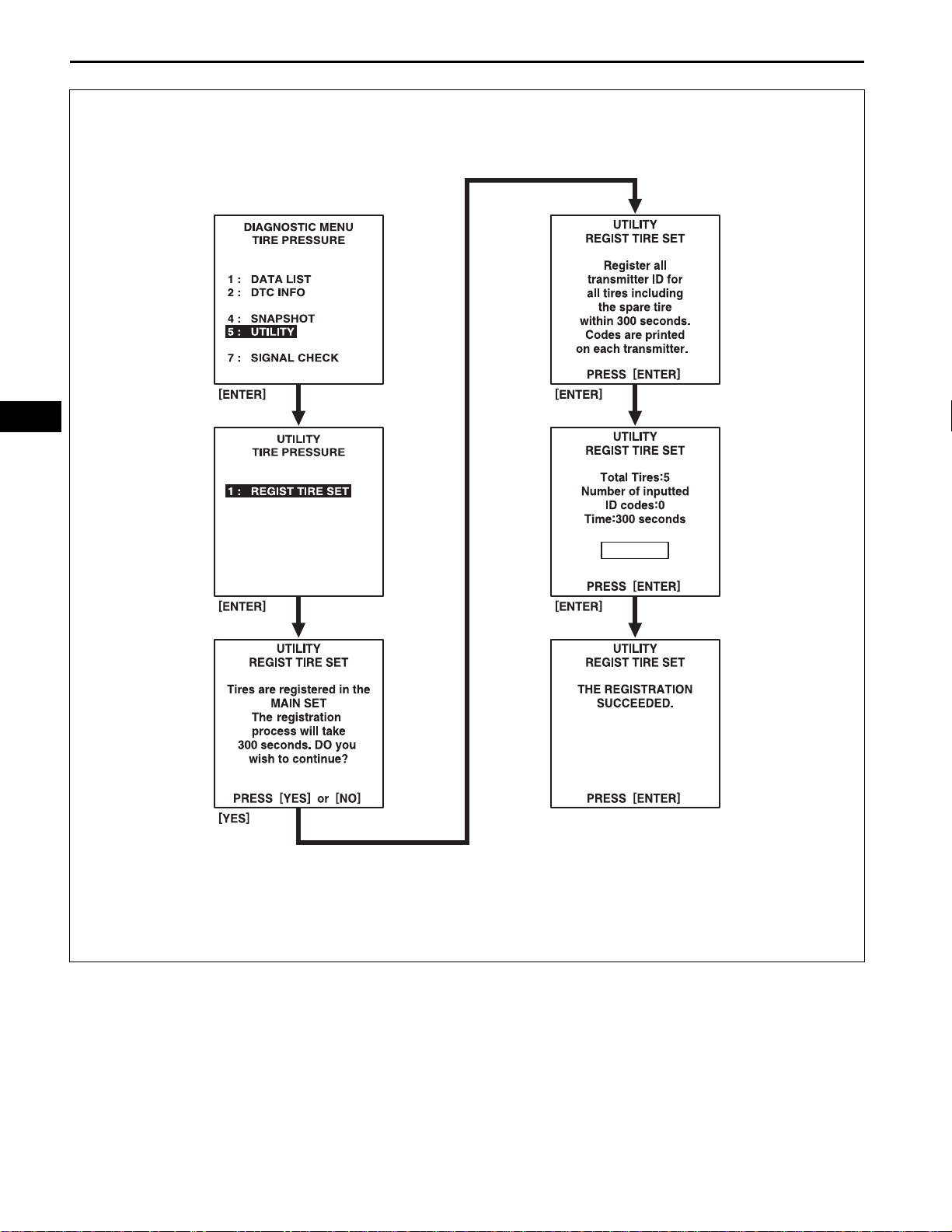
2. REGISTER TRANSMITTER ID
NOTICE:
It is necessary to register the transmitter ID in the
tire pressure warning ECU when replacing the tire
pressure warning valve and transmitter and/or tire
pressure warning ECU.
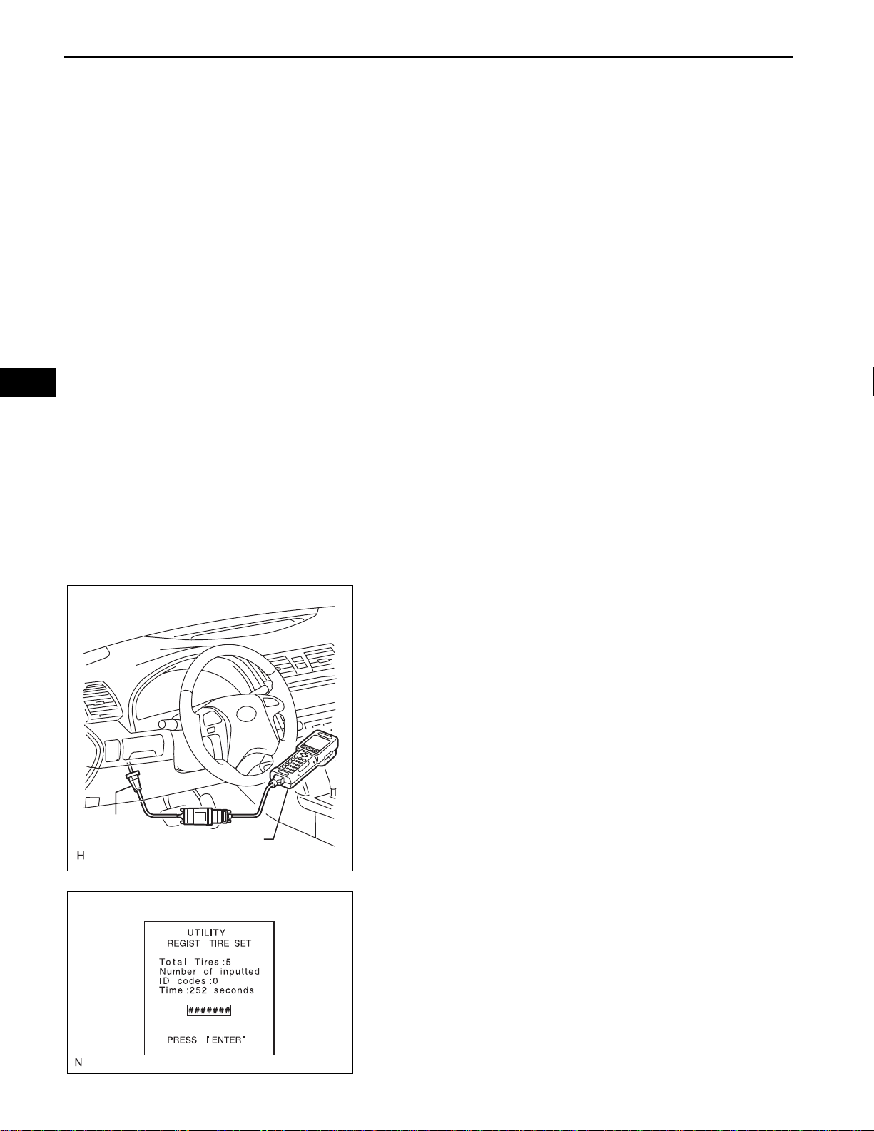
(a) Connect the intelligent tester to DLC3 (Procedure
"A").
(b) Turn the ignition switch on (IG) (Procedure "B").
(c) Select the REGIST TIRE following the intelligent
tester screen (UTILITY - REGIST TIRE) (Procedure
"C").
Intelligent Tester
C131977E09
F100622
(d) Input the IDs (ID1 to ID4 or ID5) using the intelligent
tester and transmit them to the tire pressure warning
ECU (Procedure "D").

TIRE AND WHEEL – TIRE PRESSURE WARNING SYSTEM
(e) Set the ID transmission condition to "ID Registration
is complete" (Procedure "E").
HINT:
• The previously registered IDs will be deleted
from the memory when the registration is
completed.
• If the procedures "C" to "D" are not completed
within 5 min. , the mode will return to the normal
operation mode.
C107265
• When the system is in initialization mode after
the tire pressure warning reset switch has been
operated, the registration is disabled until the
initialization process is canceled or completed.
TW–17
TW
TW
TW–18
Registration Procedure
TIRE AND WHEEL – TIRE PRESSURE WARNING SYSTEM
3. CONFIRMATION OF TRANSMITTER ID
REGISTRATION
(a) Connect the intelligent tester to DLC3 (ignition
switch is off).
(b) Turn the ignition switch on (IG).
(c) Select "TIREPRESS" by following the prompts
displayed on the intelligent tester.
F101083E01

TIRE AND WHEEL – TIRE PRESSURE WARNING SYSTEM
(d) Confirm that the data of tire pressure of all tires
(including the ground spare tire) are displayed on
the intelligent tester screen.
NOTICE:
• It may take up to 1 minute or more to update
the tire pressure data.
• If the IDs have not been registered, some of
DTC C2171/71 is set in the tire pressure
warning ECU after 51 minutes or more.
TW–19
TW

TW
TW–20
TIRE AND WHEEL – TIRE PRESSURE WARNING SYSTEM
Cold tire inflation pressure
Tire size
P215/60R16 94W
P215/55R17 93V
INITIALIZATION
1. INITIALIZATION
Front kPa (kgf/cm
210 (2.1, 31)
220 (2.2, 32)
NOTICE:
• Perform initialization after the transmitter ID
registration is completed.
• Initialization is necessary after replacing any of
the ECU, tires with different tire pressure, or tire
pressure warning valve and transmitter, or when a
new vehicle is delivered.
• Perform the tire pressure adjustment after the
vehicle has sufficiently cooled down. If the
vehicle is not sufficiently cooled down, increase
the air pressure by 20 to 30 kPa (0.2 to 0.3 kgf/
2
cm
, 2.9 to 4.3 psi) above the specified value.
(a) Set the air pressure of all wheels, including the
ground spare tire, to the specified value.
2
, psi) Rear kPa (kgf/cm2, psi)
*1
240 (2.4, 35)
*1
240 (2.4, 35)
*2
*2
210 (2.1, 31) *1 240 (2.4, 35)
220 (2.2, 32) *1 240 (2.4, 35)
*2
*2
Tire Pressure
Warning Reset
Switch
Tire Pressure Warning Light Output Pattern:
1 sec.
*1: For driving under 100 mph (160 km/h)
*2: For driving at 100 mph (160 km/h) or over
(b) Keep the tire pressure warning reset switch pressed
for 3 seconds or more with the ignition switch on
(IG).
(c) Check that the tire pressure warning light blinks 3
times (1 second ON, 1 second OFF).
HINT:
• Initialization will be completed if signals are
received from all the wheels. Initialization will be
canceled if the ignition switch is turned off during
initialization.
ON
OFF
1 sec.
E129454E01

TIRE AND WHEEL – TIRE PRESSURE WARNING SYSTEM
TW–21
DLC3:
CG
TC
(d) Wait for 2 or 3 minutes with the ignition switch on
(IG).
NOTICE:
• The initialization is normally completed
87654321
within 2 to 3 minutes.
• If the initialization has not been completed
161514131211109
successfully, DTC C2177/77 is set
approximately 20 minutes.
• The initialization can be terminated by
F100115E55
making a short circuit between terminals TC
and CG of the DLC3 connector.
(e) Confirm that the initialization has been completed
using the intelligent tester.
(1) Change the mode to test mode using intelligent
tester and check that test DTCs have been
stored.
• The test DTCs will not be indicated until the
system initialization is complete.
TW
• After the initialization has been completed
successfully, the test DTCs (C2181/81 to
C2191/91) are indicated.
NOTICE:
The following operations can be used
instead of above procedure
1. T urn the ig nition switch from off to on (IG).
2. Monitor the tire pressure values of all the
wheels using intelligent tester.
3. If the tire pressure values cannot be
displayed on the intelligent tester screen,
the initialization has failed.
4. It takes 2 to 3 minutes to display the tire
pressure data.
HINT:
• In winter, as the tire pressure may decrease
depending on the ambient temperature,
increase the tire pressure by 20 to 30 kPa
(0.2 to 0.3 kgf/cm
2
, 2.9 to 4.3 psi) above the
specified value after confirmation that the
initialization has been completed.

TW
TW–22
DLC3
TIRE AND WHEEL – TIRE PRESSURE WARNING SYSTEM
Intelligent Tester
C131977E01
TEST MODE PROCEDURE
1. ENTER TEST MODE
HINT:
• Operation of the tire pressure warning reset switch
can be checked in TEST MODE.
• During TEST MODE, the system is not initialized by
pushing the tire pressure warning reset switch. The
circuit of the tire pressure warning reset switch can be
inspected during this mode.
(a) Make sure that the ignition switch is off.
(b) Connect the intelligent tester to DLC3.
(c) Turn the ignition switch on (IG).
(d) Select the TEST MODE on intelligent tester.
(e) Confirm that the tire pressure warning light in the
combination meter blinks at 0.125 second intervals.
2. PERFORM SIGNAL CHECK
HINT:
• When entering signal check mode, the tire pressure
warning ECU sets all the signal check DTCs first.
After completing signal check for each inspection
item, the DTCs for systems that are determined to be
normal by the tire pressure warning ECU will be
erased.
The DTCs for other inspection items may not be
erased when only a certain signal is inspected.
• When signal check returns to normal mode, all the
signal check DTCs will be erased.
DLC3
(a) Make sure that the ignition switch is off.
(b) Connect the intelligent tester to DLC3.
(c) Turn the ignition switch on (IG).
Intelligent Tester
C131977E01

TIRE AND WHEEL – TIRE PRESSURE WARNING SYSTEM
(d) Select the SIGNAL CHECK on intelligent tester.
TW–23
TW
(e) Drive the vehicle at 12 mph (20 km/h) or more for 10
seconds or more. For checking the vehicle speed
signal (C2191/91).
(f) Loosen the valve core and rapidly reduce the
pressure (at least 40 kPa (0.41 kg/cm
within 30 seconds or more). For checking the
transmitter data (C2181/81 to C2185/85).
HINT:
The transmitter ID can be transmitted by rapidly
reducing the tire pressure.
(g) Check that the tire pressure warning system test
mode DTCs are erased.
SIGNAL CHECK DTC Test Signal Signal Check DTC Clear Condition
C2181/81 to C2185/85 Transmitter Data
C2191/91 Vehicle Speed Signal
Receive data from the transmitter which has a registered ID in
the tire pressure warning ECU
Vehicle speed of 12 mph (20 km/h) or more is detected for 3
seconds or more
(h) Check the tire pressure warning reset switch.
(1) Press the tire pressure warning reset switch.
(2) Check the tire pressure warning indicator light.
Test Signal Normal Condition
Tire Pressure Warning Reset Switch
• Switch ON: TPWS indicator comes on
• Switch OFF: TPWS indicator blinks
2
, 5.8 psi)
C110644

TW
TW–24
SIGNAL CHECK DTC is output Repair the faulty part and enter SIGNAL CHECK again
SIGNAL CHECK DTCs are cleared No problem
DTC No. Detection Item Trouble Area
C2181/81
(TW-38)
C2182/82
(TW-38)
C2183/83
(TW-38)
C2184/84
(TW-38)
C2185/85 (TW-38) Transmitter ID5 not received
C2191/91
(TW-61)
TIRE AND WHEEL – TIRE PRESSURE WARNING SYSTEM
Condition Procedure
Transmitter ID1 not received
Transmitter ID2 not received
Transmitter ID3 not received
Transmitter ID4 not received
Vehicle speed signal error
(i) Result
HINT:
After the signal check is completed, check for a
DTC and signal check DTC to confirm the system
status.
(j) End of SIGNAL CHECK
After completing the test mode (SIGNAL CHECK), turn the
ignition switch off and disconnect the tester.
DTC of SIGNAL CHECK (TEST DIAGNOSIS) function:
If a trouble code is displayed during the test mode DTC
check, check the circuit listed for that code. For details
of each code, refer to the relevant page listed under
respective "DTC No." in the chart.
• Tire pressure warning valve and transmitter
• Tire pressure warning antenna and receiver
• Wire harness or connector
• Tire pressure warning ECU
• Tire pressure warning valve and transmitter
• Tire pressure warning antenna and receiver
• Wire harness or connector
• Tire pressure warning ECU
• Tire pressure warning valve and transmitter
• Tire pressure warning antenna and receiver
• Wire harness or connector
• Tire pressure warning ECU
• Tire pressure warning valve and transmitter
• Tire pressure warning antenna and receiver
• Wire harness or connector
• Tire pressure warning ECU
• Tire pressure warning valve and transmitter
• Tire pressure warning antenna and receiver
• Wire harness or connector
• Tire pressure warning ECU
• Vehicle speed sensor
• Combination meter assembly
• Wire harness or connector
• Tire pressure warning ECU

TIRE AND WHEEL – TIRE PRESSURE WARNING SYSTEM
TIRE PRESSURE WARNING SYSTEM:
Symptom Suspected area See page
Tire pressure warning system does not operate.
DTC check cannot be done.
Tire pressure warning light malfunctions (Remains on).
Tire pressure warning light malfunctions (Blinking).
Initialization cannot be done.
TW–25
PROBLEM SYMPTOMS TABLE
HINT:
• Use the table below to help determine the cause of the
problem symptom. The potential causes of the symptoms
are listed in order of probability in the "Suspected Area"
column of table. Check each symptom by checking the
suspected areas in the order they are listed. Replace p arts
as necessary.
• Inspect the fuses and relays related to this system before
inspecting the suspected areas below.
1. Tire pressure warning valve and transmitter TW-77
2. Tire pressure warning antenna and receiver TW-73
3. Power source circuit TW-67
4. TC and CG terminal circuit TW-69
5. Combination meter assembly ME-15
6. Tire pressure warning ECU TW-82
1. Power source circuit TW-82
2. TC and CG terminal circuit TW-69
3. Tire pressure warning ECU TW-82
1. Tire pressure check TW-3
2. Initialization TW-18
3. Tire pressure warning ECU connector poorly connected TW-24
4. Tire pressure warning light circuit TW-65
5. Tire pressure warning ECU TW-82
1. Check DTC TW-28
2. Tc and CG terminal circuit TW-69
3. Test mode (SIGNAL CHECK) TW-20
4. Tire pressure warning ECU TW-82
1. Test mode (SIGNAL CHECK) TW-20
2. Tire pressure reset switch TW-85
3. Tire pressure warning ECU TW-82
TW
TW
TW–26
TIRE AND WHEEL – TIRE PRESSURE WARNING SYSTEM
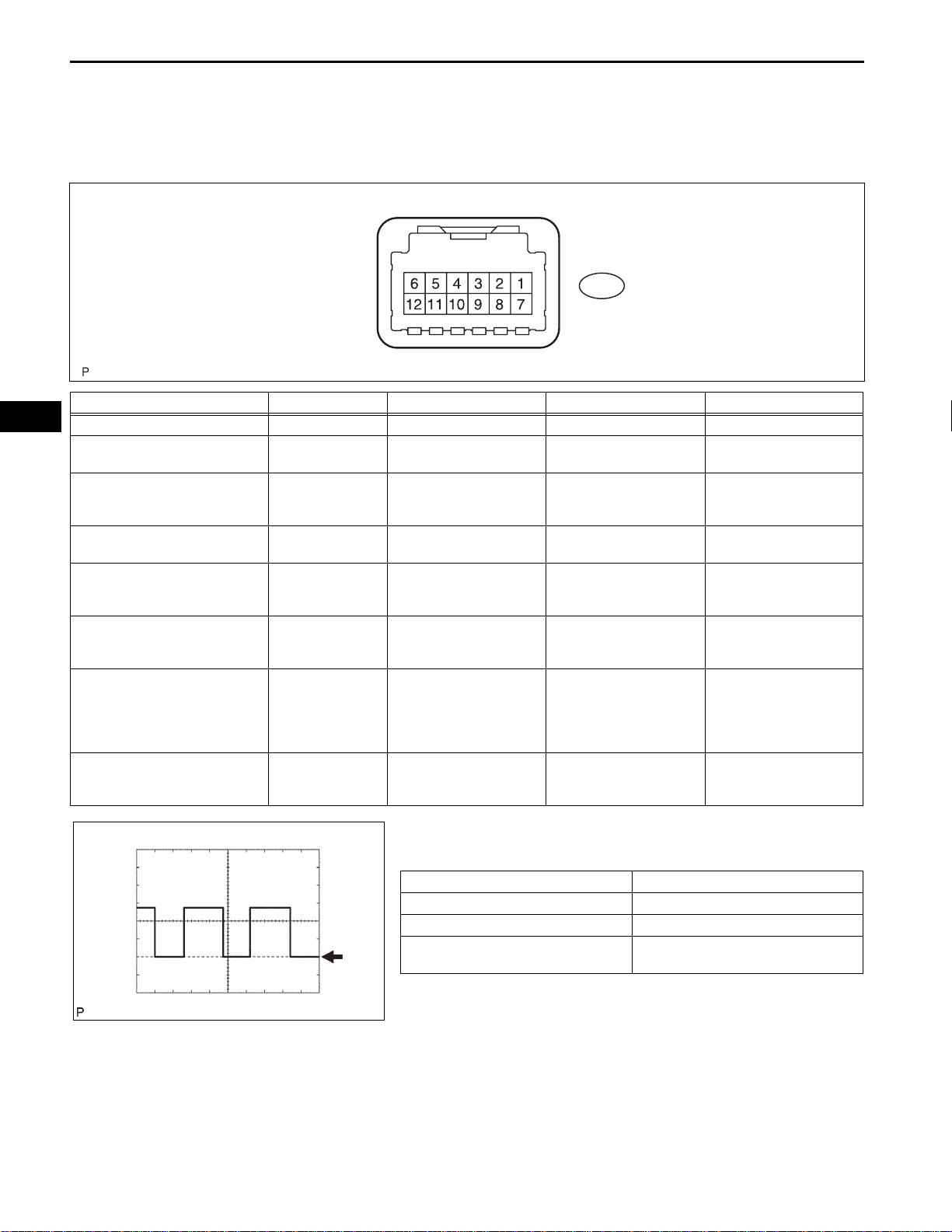
TERMINALS OF ECU
HINT:
Inspect the connectors from the back side while the
connectors are connected.
E60
Symbols (Terminal No.) Wiring Color Terminal Description Condition Specified Condition
IG (E60-7) - GND (E60-9) B - W-B IG power source Ignition switch on (IG) 10 to 16 V
SPD (E60-2) - GND (E60-9) V - W-B Vehicle speed signal Ignition switch on (IG)
• Ignition switch on (IG)
• Intelligent tester is
connected to DLC3
Ignition switch on (IG) 10 to 16 V
Ignition switch on (IG) 4.5 to 5.5 V
• Ignition switch on (IG)
• Tire pressure warning
reset switch on
• Ignition switch on (IG)
• The Tire pressure
warning antenna and
receiver is not
connected
Always Below 1 Ω
SIL (E60-10) - GND (E60-9) GR - W-B
IND (E60-5) - GND (E60-9) L - W-B
RF5V (E60-6) - GND (E60-9) LC - W-B
CLSW (E60-1) - GND (E60-9) O - W-B
RDA (E60-12) - GND (E60-9) G - W-B
GND2 (E60-11) - GND (E60-9) BR - W-B
Diagnostic communication
terminal
Tire pressure warning light
signal
Tire pressure warning
antenna and receiver
power source
Tire pressure warning
reset switch
Tire pressure warning
antenna and receiver
signal
Tire pressure warning
antenna and receiver
ground
Pulse generation (See
waveform 1)
Pulse generation (See
waveform 2)
8 to 15V
9 to 16 V
E129452E01
GND
F047507E05
1. Waveform 1 (Reference)
(a) Waveform
Item Contents
Terminal SPD - GND
Tool setting 5V/DIV, 200ms/DIV.
Vehicle condition
While driving at approximately 12 mph
(20 km/h).
5 V
TIRE AND WHEEL – TIRE PRESSURE WARNING SYSTEM
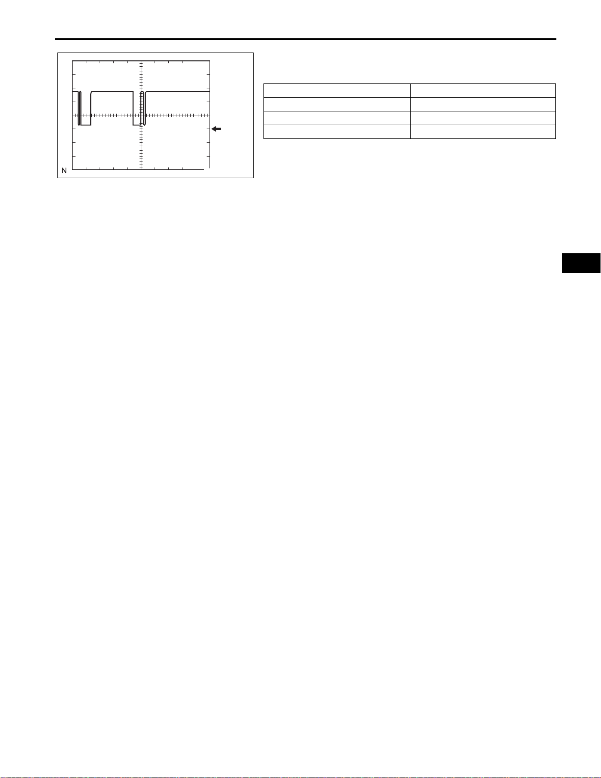
2. Waveform 2 (Reference)
1 ms
GND
C107353E03
(a) Waveform
Item Contents
Terminal SIL - Body ground
Tool setting 5 V/DIV., 1 ms/DIV.
Vehicle condition Communicating using intelligent tester
TW–27
TW
TW–28
CG
SG
TIRE AND WHEEL – TIRE PRESSURE WARNING SYSTEM
DIAGNOSIS SYSTEM
1. CHECK BATTERY VOLTAGE
Standard voltage:
11 to 14 V
If the voltage is below 11 V, recharge the battery before
proceeding.
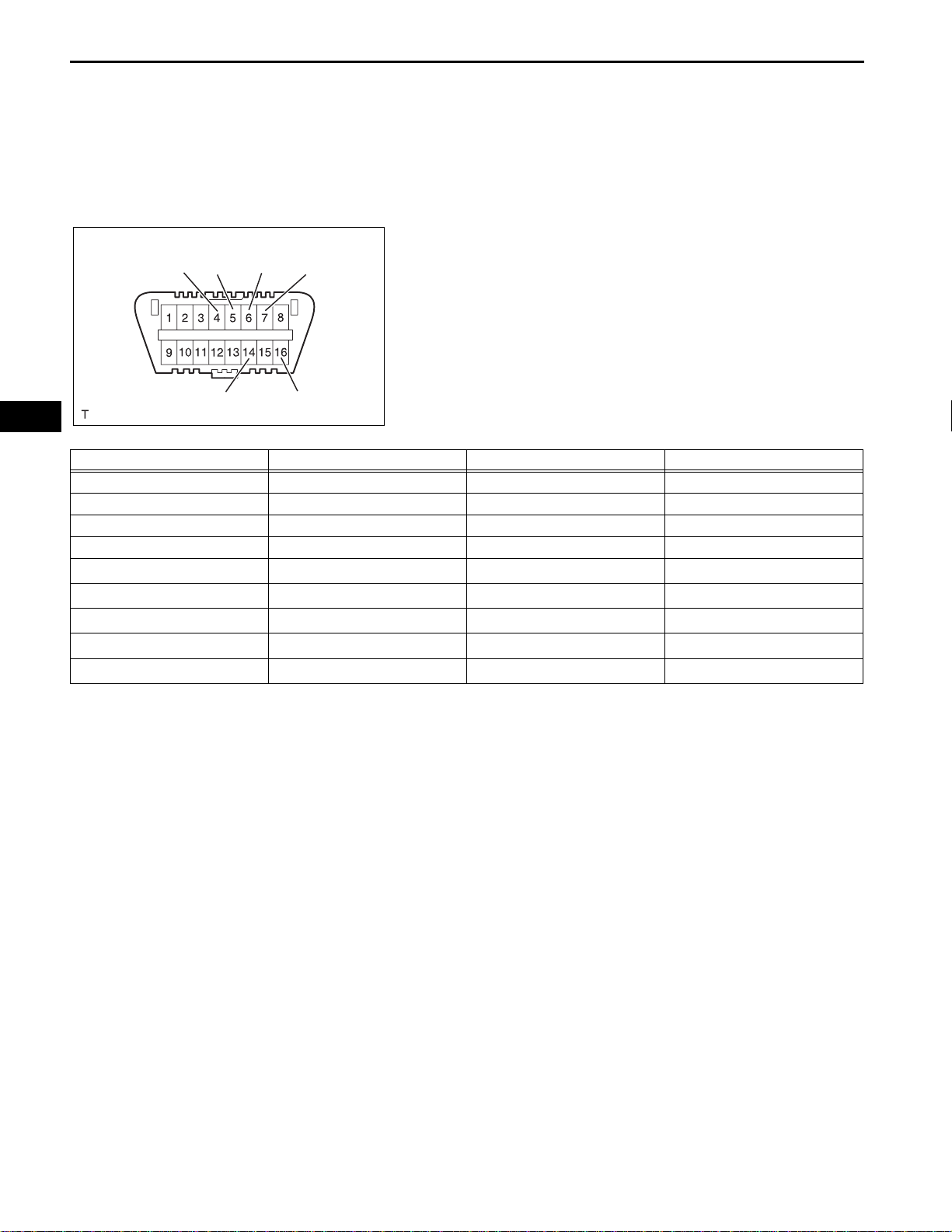
2. CHECK DLC3
(a) The ECU uses the ISO 15765-4 for communication
CANH
SIL
protocol. The terminal arrangement of the DLC3
complies with SAE J1962 and matches the ISO
15765-4 format.
TW
CANL
Symbols (Terminal NO. ) Terminal Description Condition Specified Condition
SIL (7) - SG (5) Bus "+" line During transmission Pulse generation
CG (4) - Body ground Chassis ground Always Below 1 Ω
SG (5) - Body ground Signal ground Always Below 1 Ω
BAT (16) - Body ground Battery positive Always 11 to 14 V
CANH (6) - CANL (14) CAN bus line
CANH (6) - CG (4) HIGH-level CAN bus line
CANL (14) - CG (4) LOW-level CAN bus line
CANH (6) - BAT (16) HIGH-level CAN bus line
CANL (14) - BAT (16) LOW-level CAN bus line
BAT
H100769E16
Ignition switch off
Ignition switch off
Ignition switch off
Ignition switch off
Ignition switch off
*
*
*
*
*
54 to 69 Ω
200 Ω or higher
200 Ω or higher
6 kΩ or higher
6 kΩ or higher
NOTICE:
*
Before measuring the resistance, leave the
vehicle as is for at least 1 minute and do not
operate the power switch, or any other switches
or the doors.
(b) If the result is not as specified, DLC3 may have a
malfunction. Repair or replace the harness and
connector.
HINT:
Connect the cable of the intelligent tester to DLC3,
turn the ignition switch on (IG) and attempt to use
the tester. If the display indicates that a
communication error has occurred, there is a
problem either with the vehicle or with the tester.
• If communication is normal when the tester is
connected to another vehicle, inspect DLC3 of
the original vehicle.
• If communication is still not possible when the
tester is connected to another vehicle, the
problem may be in the tester itself. Consult the
Service Department listed in the tester's
instruction manual.
 Loading...