

Toyota Camry 2007-2009 Service Manual - 07_Collision
FOREWORD
This repair manual has been prepared to provide essential information on body panel repair methods (including cutting and
welding operations, but excluding painting) for the TOYOTA
CAMRY.
Applicable models: ACV 40 series
GSV 40 series
This manual consists of body repair methods, exploded diagrams and illustrations of the body components and other information relating to body panel replacement such as handling
precautions, etc. However, it should be noted that the front fenders of this TOYOTA model are bolted on and require no welding.
When repairing, don’t cut and join areas that are not shown in
this manual. Only work on the specified contents to maintain
body strength.
Body construction will sometimes differ depending on specifications and country of destination. Therefore, please keep in mind
that the information contained herein is based on vehicles for
general destinations.
For the repair procedures and specifications other than collisiondamaged body components of the TOYOTA CAMR Y refer to th e
repair manuals.
If you require the above manuals, please contact your TOYOTA
dealer.
All information contained in this manual is the most up-to-date at
the time of publication. However, specifications and procedures
are subject to change without prior notice.

ABOUT THIS MANUAL
Scope of the repair work explanation
This text explains the welding panel replacement instructions from the vehicle’s white body condi-
tion. W e have abbreviated the explanations of the removal and reinstallation of the equipment parts
up to the white body condition and of the installation, inspection, adjustment and final inspection of
equipment parts after replacing the weld panel.
Section categories
This manual has been divided as shown below.
Section Title Contents Examples
INTRODUCTION
BODY PANEL REPLACEMENT
BODY DIMENSIONS Body aligning measurements. Dimension diagrams.
PAINT COATING
Explanation of general body repair.
Views of weld panel replacement instructions.
Instructions for replacing the weld panels
from the white body condition, from which
bolted parts have been removed, with
individual supply parts.
Scope and type of anti-rust treatment, etc.
together with weld panel replacement.
Contents omitted in this manual.
Make sure to perform the following essential procedures, although they are omitted in this manual.
(1) Clean and wash removed parts, if necessary.
(2) Visual inspection.
Cautionary items.
Views of weld panel replacement instructions.
Front side member replacement.
Quarter panel replacement.
Under coating.
Body sealer.
Glass Cover
Seat Cover
INTRODUCTION
PRECAUTION
GENERAL REPAIR INSTRUCTIONS
1. WORK PRECAUTIONS
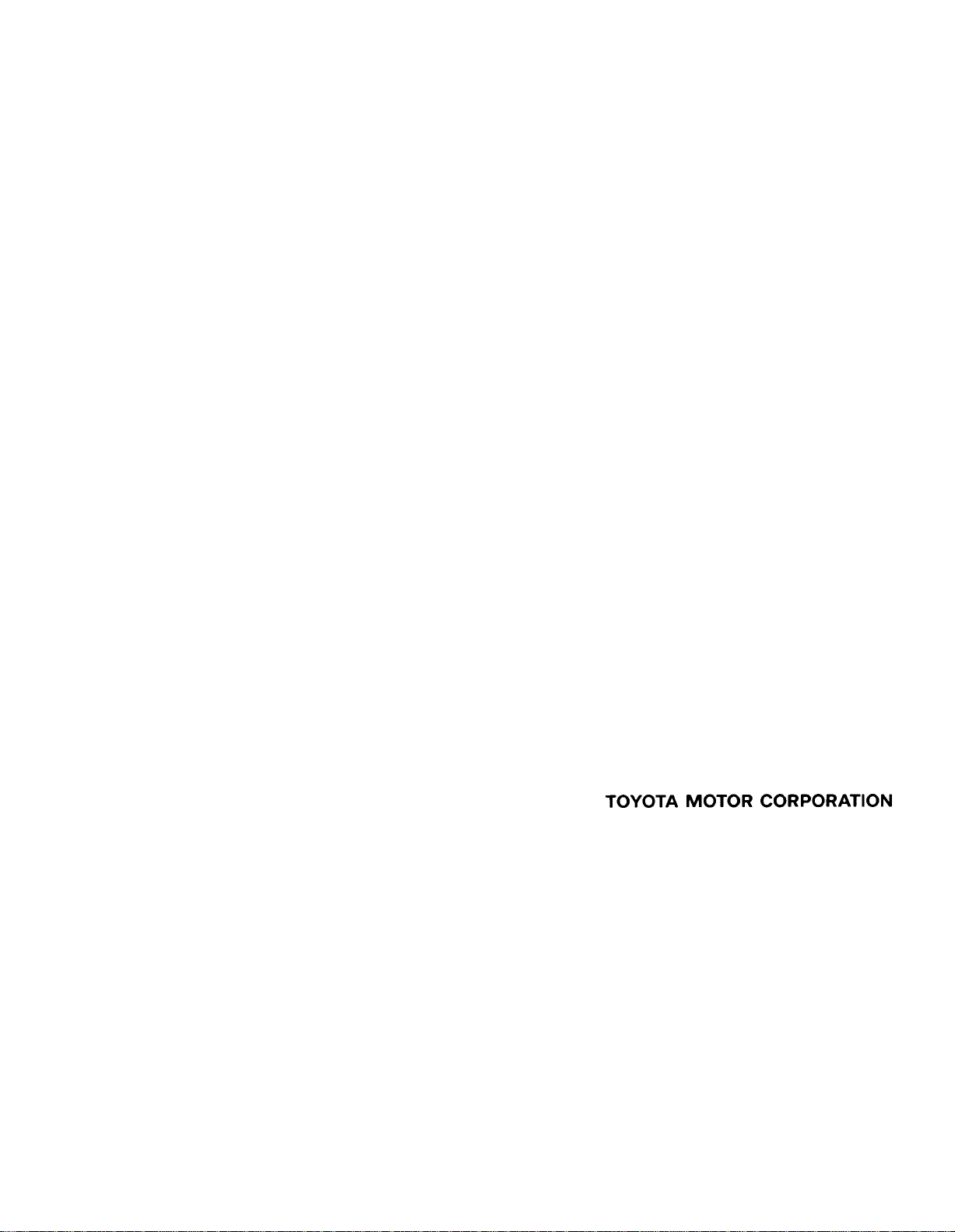
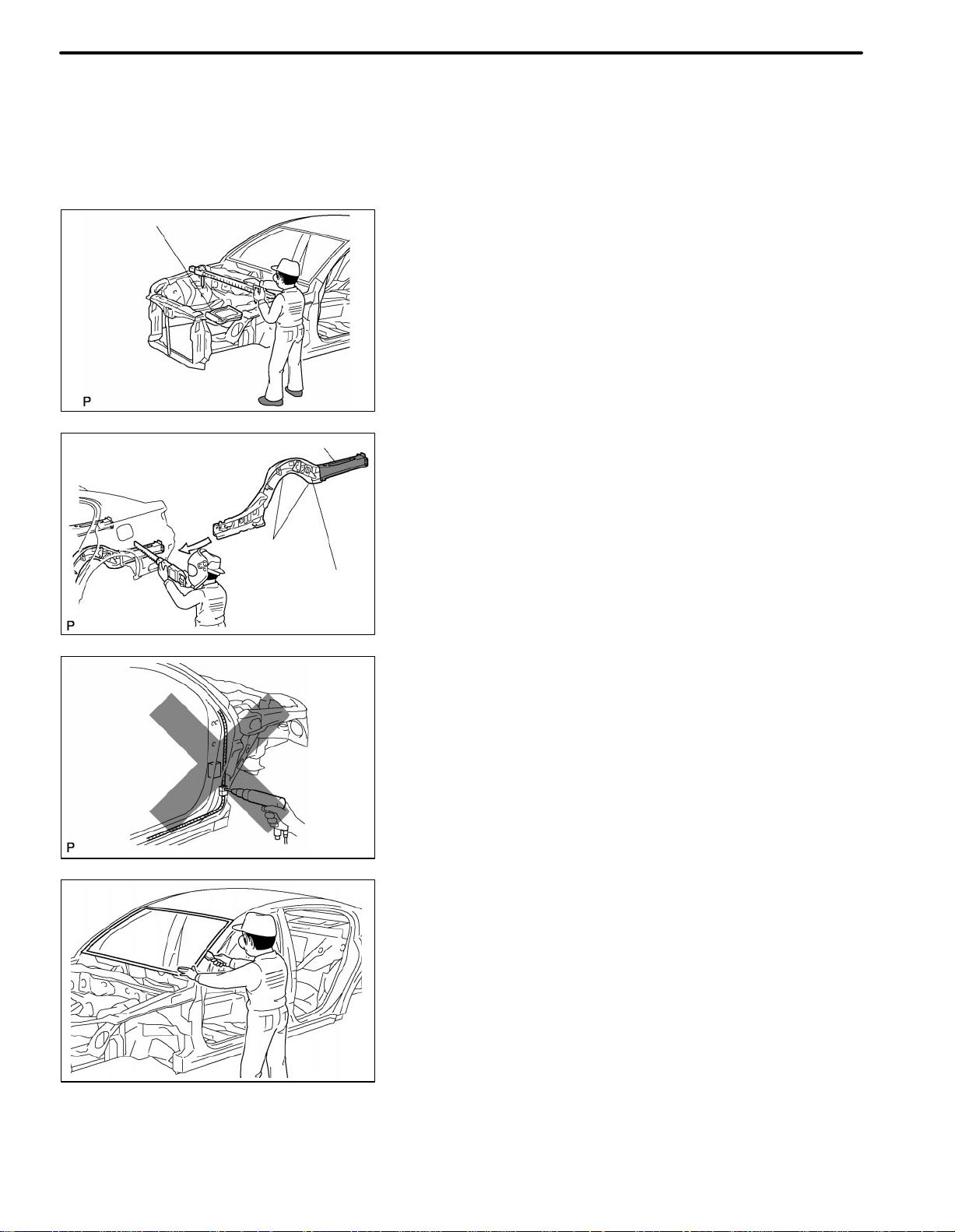
(a) VEHICLE PROTECTION
(1) When welding, protect the painted surfaces, windows,
seats and carpet with heat resistant, fireproof covers.
F33000
(b) SAFETY
(1) Never stand in a direct line with the chain when using a
puller on the body or frame, and be sure to attach a
safety cable.
IN-1
WRONG
WRONG
F33001
F33002
F33003
(2) Before performing repair work, check for fuel leaks.
If a leak is found, be sure to close the opening completely.
(3) If it is necessary to use a flame in the area of the fuel
tank, first remove the tank and plug the fuel line.
(c) SAFETY WORK CLOTHES
(1) In addition to the usual mechanic’s wear, cap and
safety shoes, the appropriate gloves, head protector,
glasses, ear plugs, face protector, dust-prevention
mask, etc. should be worn as the situation demands.
Code Name
A Dust-Prevention Mask
B Face Protector
C Eye Protector
D Safety Shoes
E Welder’s Glasses
F Ear Plugs
G Head Protector
H Welder’s Gloves
IN-2
F33014
INTRODUCTION
PRECAUTIONS FOR REPAIRING BODY
STRUCTURE PANELS
1. HEAT REPAIR FOR BODY STRUCTURE
PANELS
Toyota prohibits the use of the heat repair method on body
structure panels when repairing a vehicle damaged in a collision.
Panels that have high strength and rigidity, as well as a long
life span for the automobile body are in high demand.
At Toyota, in order to fulfill these requirements, we us e h igh
tensile strength steel sheets and rust preventive steel
sheets on the body. High tensile steel sheets are made with
alloy additives and a special heat treatment in order to improve their strength.
To prevent the occurrence of rust for a long period of time,
the surface of the steel is coated with a zinc alloy.
If body structure parts are heat repaired with an acetylene
torch or ot h e r heating source, the crystalline organization of
the steel sheet will change and their strength of the steel
sheet will be reduced. The ability of the body to resist rust is
significantly lowered as well since the rust resistant zinc
coating is destroyed by heat and the steel sheet surface is
oxidized.
F33015
2. STRUCTURE PANEL KINKS
A sharp deformation angle on a panel that cannot be returned to its original shape by pulling or hammering is
called a kink.
Structural parts are designed to perform in their original
shape. If parts are deformed in an accident, or if the deformed parts are repaired and reused, the parts may be unable to perform as intended.
It is necessary to replace the part where the kink has occurred.
F33016
F33017
INTRODUCTION
3. IMPACT BEAM REPAIR
The impact beam and bracket are necessary and important
parts that help reduce the probability of injury to passengers in side collisions.
For impact beams, we use special high tensile strength
steel.
The high tensile strength steel maintains its special crystalline organization by heat treatment or alloy additives.
Structural parts are designed to perform in their original
shape. If parts are deformed in an accident, or if the deformed part s a r e r epaired and reused, the parts may be unable to perform as intended.
If the impact beam or bracket is damaged, replace the door
assembly that has the damaged beam.
Also, the bumper reinforcement is a necessary and important part that helps reduce the probability of injury to passengers in front collisions, and for the same reasons explained above, should be replaced if damaged.
IN-3
IN-4
INTRODUCTION
PROPER AND EFFICIENT WORK
PROCEDURES
Body Measument Diagrams
Cutting Okay
Corners
Reinforcement
1. REMOVAL
(a) PRE-REMOVAL MEASURING
(1) Before removal or cutting operations, take measure-
ments in accordance with the dimensions diagram. Always use a puller to straighten a damaged body or
frame.
F33020
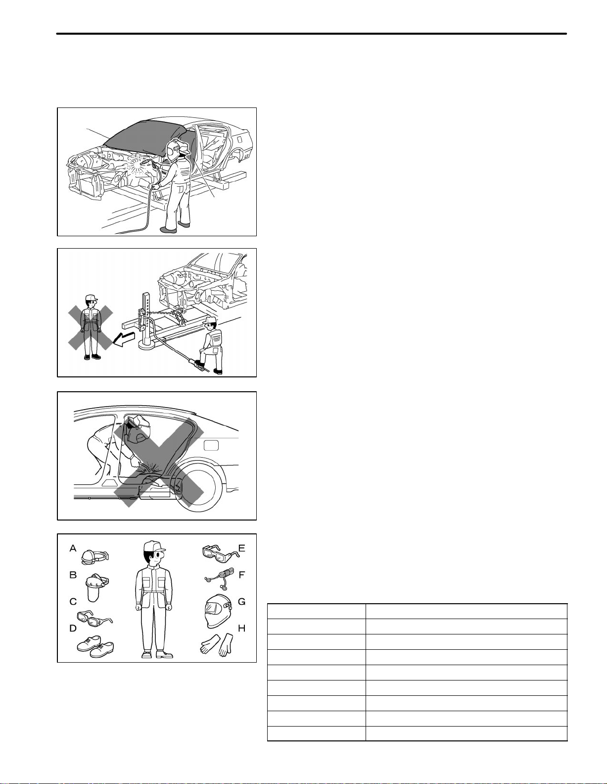
(b) CUTTING AREA
(1) Always cut in a straight line and avoid cutting rein-
forced areas.
F33021
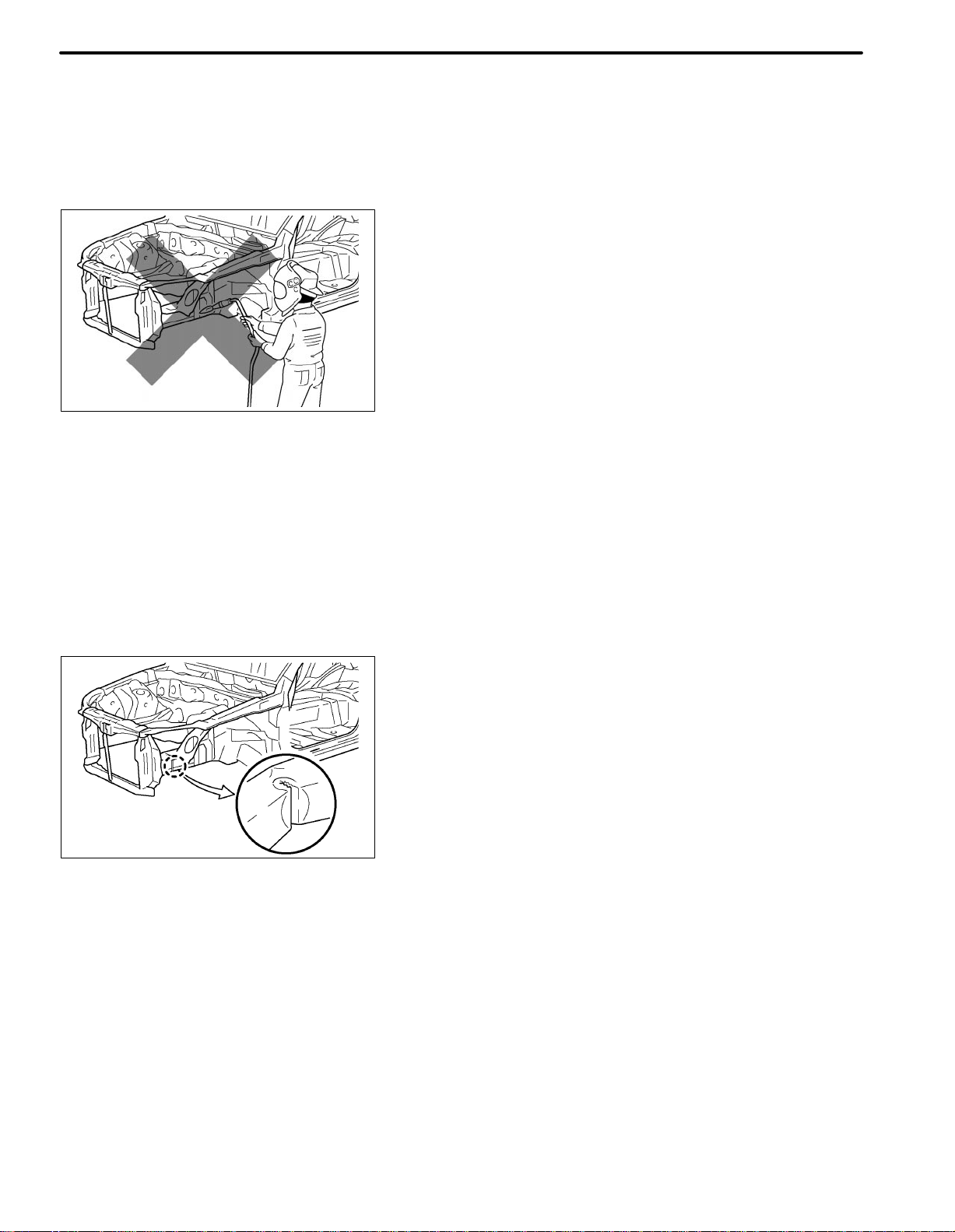
(c) PRECAUTIONS FOR DRILLING OR CUTTING
(1) Check behind any area to be drilled or cut to ensure
that there are no hoses, wires, etc., that may be damaged.
HINT: See “Handling Precautions on Related Components” on page IN-9.
WRONG
F33022
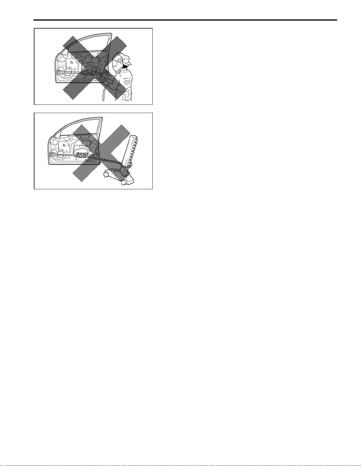
(d) REMOVAL OF ADJACENT COMPONENTS
(1) When removing adjacent components, apply protec-
tive tape to the surrounding body and your tools to prevent damage.
HINT: See “Handling Precautions on Related Components” on page IN-9.
F33007
Less than
3 mm
F10011A
F33008
INTRODUCTION
2. PREPARATION FOR INSTALLATION
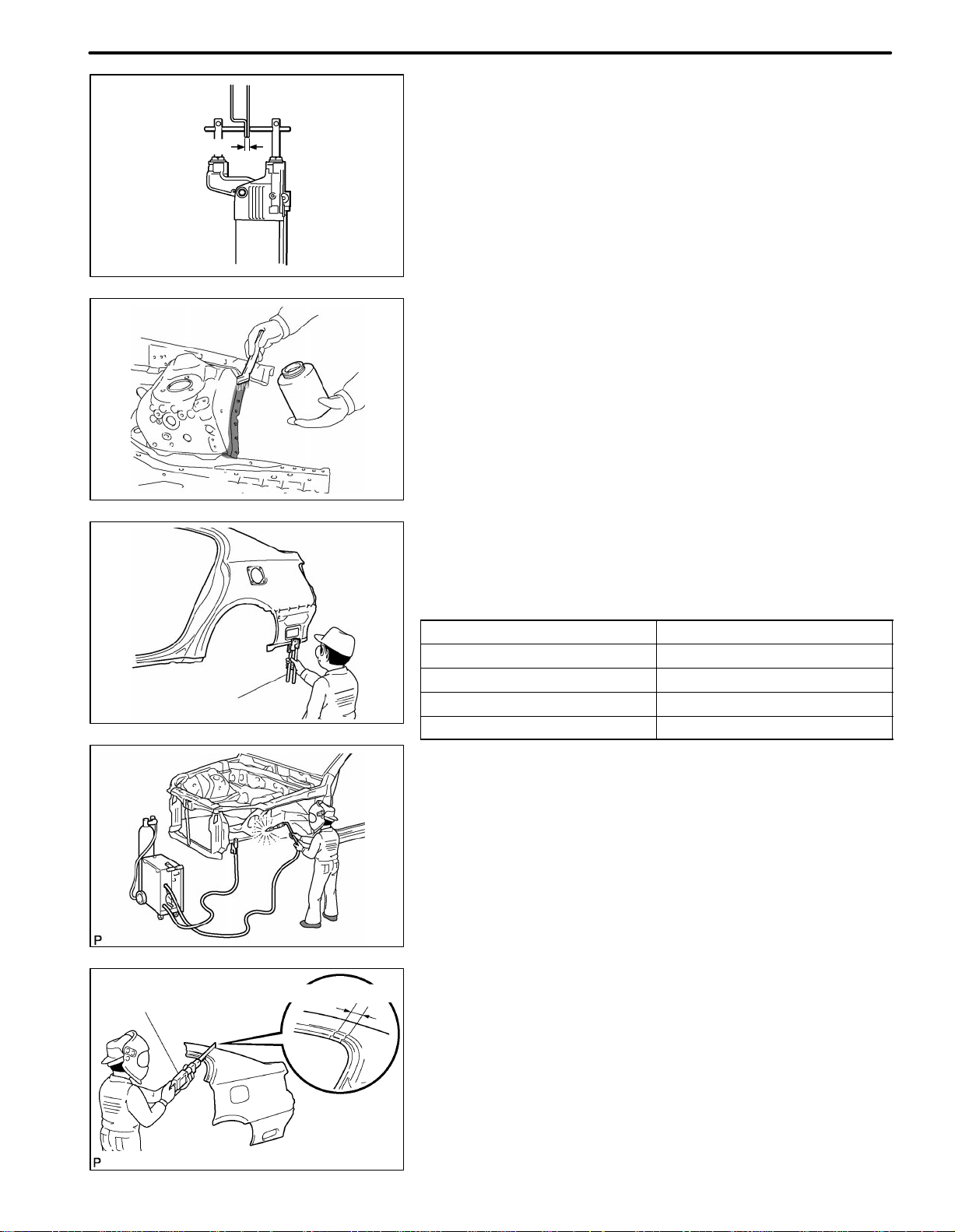
(a) SPOT WELD POINTS
(1) When welding panels with a combined thickness of
over 3 mm (0.12 in.), use a MIG (Metal Inert Gas)
welder for plug welding.
HINT: Spot welding does not provide sufficient durability for panels with a combined thickness of over 3
mm (0.12 in.)
(b) APPLICATION OF WELD-THROUGH PRIMER
(SPOT SEALER)
(1) Remove the paint from the portion of the new parts
and body to be welded, and apply weld-through primer.
IN-5
Air Saw
Puncher
F33009
F33023
20 − 30 mm Overlap
(c) MAKING HOLES FOR PLUG WELDING
(1) For areas where a spot welder cannot be used, use a
puncher or drill to make holes for plug welding.
REFERENCE: mm (in.)
Thickness of welded portion Size of plug hole
1.0 (0.04) under ø 5 (0.20) over
1.0 (0.04) − 1.6 (0.06) ø 6.5 (0.26) over
1.7 (0.07) − 2.3 (0.09) ø 8 (0.31) over
2.4 (0.09) over ø 10 (0.39) over
(d) SAFETY PRECAUTIONS FOR ELECTRICAL
COMPONENTS
(1) When welding, there is a danger that electrical compo-
nents will be damaged by the electrical current flowing
through the body.
(2) Before starting work, disconnect the negative terminal
of the battery and ground the welder near the welding
location of the body.
(e) ROUGH CUTTING OF JOINTS
(1) For joint areas, rough cut the new parts, leaving 20 −
30 mm (0.79 − 1.18 in.) of overlap.
F33024
IN-6
INTRODUCTION
3. INSTALLATION
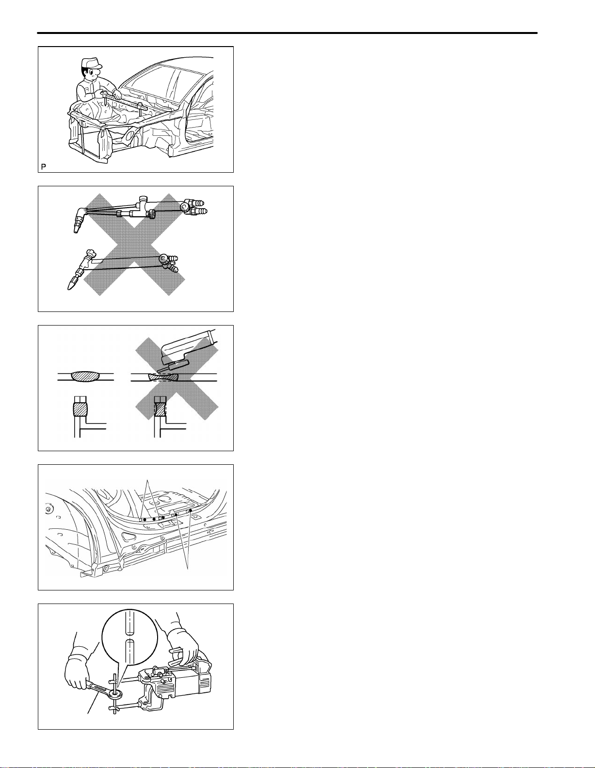
(a) PRE-WELDING MEASUREMENTS
(1) Always take measurements before installing under-
body or engine components to ensure correct assembly. After installation, confirm proper fit.
F33025
(b) WELDING PRECAUTIONS
(1) The number of welding spots should be as follows.
Spot weld: 1.3 X No. of manufacturer’s spots.
Plug weld: More than No. of manufacturer’s plugs.
(2) Plug welding should be done with a MIG (Metal Inert
Gas) welder. Do not gas weld or braze panels at areas
other than where specified.
WRONG
CORRECT WRONG
Old Spot Locations
New Spot Locations
F10017A
(c) POST-WELDING REFINISHING
(1) Always check the welded spots to ensure that they are
secure.
(2) When smoothing out the weld spots with a disc grind-
er, be careful not to grind off too much as this will weaken the weld.
F10018A
(d) SPOT WELD LOCATIONS
(1) Avoid welding over previously welded areas.
F33010
Tip Cutter
F10019A
(e) SPOT WELDING PRECAUTIONS
(1) The shape of the tip point of the spot welder signifi-
cantly affects the strength of the weld. Therefore,
maintain the tip point in the proper shape, and allow it
to cool after every five or six spots.
(2) Completely remove the paint from the areas to be spot
welded, including the seams and the surfaces that
come in contact with the welding tip.
(3) Use a sander to remove any burrs that are created
during spot welding.
INTRODUCTION
IN-7
Sealer Gun
4. ANTI-RUST TREATMENT AFTER
INSTALLATION (BEFORE PAINTING
PROCESS)
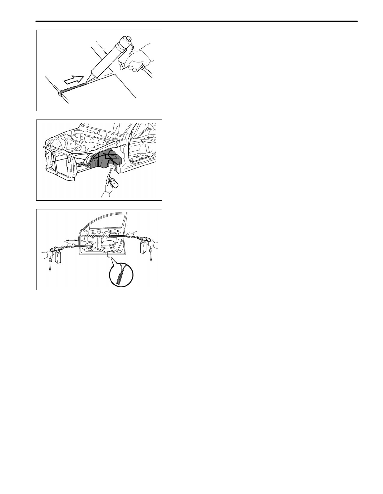
(a) BODY SEALER APPLICATION
(1) For water-proofing and anti-corrosion measures, al-
ways apply the body sealer to the body panel seams
and hems of the doors, hood, etc.
F33011
(b) UNDERCOAT APPLICATION
(1) To prevent corrosion and protect the body from dam-
age by flying stones, always apply sufficient under
coating to the bottom surface of the under body and
inside of the wheel housings.
F33012
F33013
5. ANTI-RUST TREATMENT AFTER
INSTALLATION (AFTER PAINTING PROCESS)
(a) ANTI-RUST AGENT (WAX) APPLICATION
(1) To preserve impossible to paint areas from corrosion,
always apply sufficient anti-rust agent (wax) to the inside of th e hemming areas of the doors and hood, and
around the hinges, or the welded surfaces inside the
box-shaped cross sections of the side members, body
pillars, etc.
IN-8
INTRODUCTION
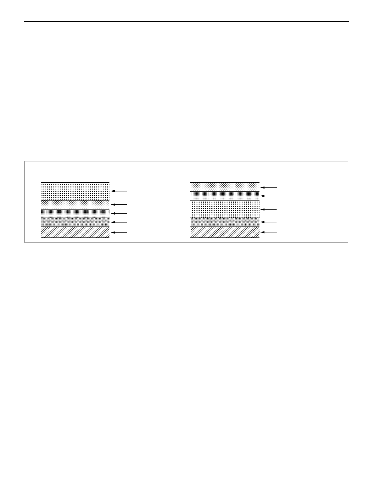
6. ANTI-RUST TREATMENT BY PAINTING
REFERENCE:
Painting prevents corrosion and protects the sheet
metal from damage. In this section, anti-chipping paint
only for anti-corrosion purposes is described.
(a) ANTI-CHIPPING PAINT
(1) To prevent corrosion and protect the body from dam-
age by flying stones, etc., apply anti-chipping paint to
the rocker panel, wheel arch areas, balance panel,
etc.
HINT:
Depending on the model or the application area, there
are cases where the application of anti-chipping paint
is necessary before the second coat or after the top
coat.
Apply the anti-chipping paint after
the top coat.
Anti-Chipping Paint
Top Coat
Second Coat
Under Coat (ED Primer)
Steel Metal
Apply the anti-chipping paint before
the second coat.
Top Coat
Second Coat
Anti-Chipping Paint
Under Coat (ED Primer)
Steel Metal
F10024A

INTRODUCTION
HANDLING PRECAUTIONS ON RELATED COMPONENTS
1. BRAKE SYSTEM
The brake system is one of the most important safety components. Always follow the directions and
notes given in the brake section of the repair manual for the relevant model year when handling brake
system parts.
NOTICE: When repairing the brake master cylinder or TRAC system, bleed the air out of the TRAC system.
2. DRIVE TRAIN AND CHASSIS
The drive train and chassis are components that can have great effects on the running performance and
vibration resistance of the vehicle. After installing components in the sections listed in the table below,
perform alignments to ensure correct mounting angles and dimensions. Body repair must be particularly
accurate to ensure correct alignment.
HINT: Correct procedures and special tools are required for alignment. Always follow the directions given in the repair manual for the relevant model year during alignment and in section DI of this section.
IN-9
Component to be aligned
Front Wheels Front Suspension section
Rear Wheels Rear Suspension section
Section of repair manual
for relevant model
3. COMPONENTS ADJACENT TO THE BODY PANELS
Various types of component parts are mounted directly on or adjacently to the body panels. Strictly observe the following precautions to prevent damaging these components and the body panels during handling.
Before repairing the body panels, remove their components or apply protective covers over the com-
ponents.
Before prying components off using a screwdriver or a scraper, etc., attach protective tape to the tool
tip or blade to prevent damaging the components and the body paint.
Before removing components from the outer surface of the body, attach protective tape to the body to
ensure no damage to painted areas.
HINT: Apply touch-up paint to any damaged paint surfaces.
Before drilling or cutting sections, make sure that there are no wires, etc., on the reverse side.
4. ECU (ELECTRONIC CONTROL UNIT)
Many ECUs are mounted in this vehicle.
Take the following precautions during body repair to prevent damage to the ECUs.
Before starting electric welding operations, disconnect the negative (−) terminal cable from the bat-
tery.
When the negative (−) terminal cable is disconnected from the battery, the memory of the clock and
audio systems will be erased. So, before starting work, make a record of the contents memorized by
each memory system. Then when work is finished, reset the clock and audio systems as before.
When the vehicle has tilt and telescopic steering, power seats and outside rear view mirrors, which are
all equipped with a memory function, it is not possible to make a record of the memory contents.
When the operation is finished, it will be necessary to explain this fact to the customer , and request the
customer to adjust the features and reset the memory.
Do not expose the ECUs to ambient temperatures above 80C (176F).
NOTICE: Since it is possible that the ambient temperature may reach 80C (176F) or more, remove
the ECUs from the vehicle before starting work.
Be careful not to drop the ECUs and not to apply physical shocks to them.
IN-10
INTRODUCTION
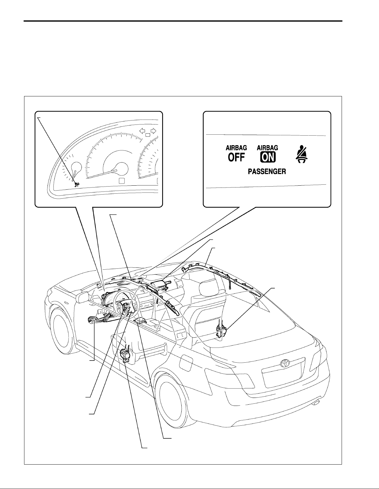
DAMAGED VEHICLE D ISPOSAL P RECAUTION ( SRS A IRBAG S YSTEM)
For SRS airbag system adjustment methods, refer to the TOYOTA Repair Manual.
(1) When using an electric welder, first remove all airbags and the seat belt pretensioner.
(2) If impacts are likely to occur to the front airbag sensor, side airbag sensor, rear airbag sensor or seat
position sensor, remove each sensor as necessary beforehand.
(3) Do not allow the front airbag sensor, side airbag sensor, rear airbag sensor or seat position sensor to
become heated to high temperatures.
COMBINATION METER ASSEMBLY: CLOCK ASSEMBLY:
SRS WARNING LIGHT
PASSENGER AIRBAG ON/OFF INDICATOR
CURTAIN SHIELD AIRBAG
ASSEMBLY LH
FRONT PASSENGER AIRBAG ASSEMBLY
CURTAIN SHIELD AIRBAG ASSEMBLY RH
FRONT SEAT OUTER
BELT ASSEMBLY RH
DRIVER SIDE KNEE
AIRBAG ASSEMBLY
SPIRAL CABLE
STEERING PAD
CENTER AIRBAG SENSOR ASSEMBLY
FRONT SEAT OUTER BELT ASSEMBLY LH
C123719

REAR AIRBAG SENSOR RH
FRONT SEAT SIDE AIRBAG ASSEMBLY RH
SIDE AIRBAG SENSOR RH
INTRODUCTION
IN-11
FRONT SEAT SIDE AIRBAG ASSEMBLY LH
REAR AIRBAG SENSOR LH
FRONT AIRBAG SENSOR LH
FRONT AIRBAG SENSOR RH
SIDE AIRBAG SENSOR LH
SEAT POSITION SENSOR
FRONT SEAT INNER BELT ASSEMBLY LH
OCCUPANT CLASSIFICATION ECU
C123718

IN-12
INTRODUCTION
HANDLING PRECAUTIONS OF PLASTIC BODY PARTS
1. The repair procedure for plastic body parts must conform with the type of plastic material.
2. Plastic body parts are identified by the codes in the following table.
3. When repairing metal body parts adjoining plastic body parts (by brazing, frame cutting, welding, painting etc.), consideration must be given to the properties of the plastic.
*
Heat
Code
Material
name
resistant
temperature
limit C (F)
Resistance to
alcohol or gasoline
Notes
AAS
ABS
AES
ASA
EPDM
PA
PBT
PC Polycarbonate
Acrylonitrile
Acrylic Styrene
Acrylonitrile
Butadiene Styrene
Acrylonitrile
Ethylene Styrene
Acrylonitrile
Styrene
Acrylate
Ethylene
Propylene
Polyamide
(Nylon)
Polybutylene
Terephthalate
80
(176)
80
(176)
80
(176)
80
(176)
100
(212)
80
(176)
160
(320)
120
(248)
Alcohol is harmless if applied only for
short time in small amounts (e.g., quick
wiping to remove grease).
Alcohol is harmless if applied only for
short time in small amounts (e.g., quick
wiping to remove grease).
Alcohol is harmless if applied only for
short time in small amounts (e.g., quick
wiping to remove grease).
Alcohol is harmless if applied only for
short time in small amounts (e.g., quick
wiping to remove grease).
Alcohol is harmless.
Gasoline is harmless if applied only for
short time in small amounts.
Alcohol and gasoline are harmless. Avoid battery acid.
Alcohol and gasoline are harmless. Most solvents are harmless.
Alcohol is harmless.
Avoid gasoline and organic
or aromatic solvents.
Avoid gasoline and organic
or aromatic solvents.
Avoid gasoline and organic
or aromatic solvents.
Avoid gasoline and organic
or aromatic solvents.
Most solvents are harmless
but avoid dipping in gasoline,
solvents, etc.
Avoid gasoline, brake fluid,
wax, wax removers and
organic solvents. Avoid alkali.
POM
PP Polypropylene
PMMA
PVC
TPO
TSOP
*Temperatures higher than those listed here may result in material deformation during repair.
Polyoxymethylene
(Polyacetal)
Polymethyl
Methacrylate
Polyvinylchloride
(Vinyl)
Thermoplastic
Olefine
TOYOTA
Super
Olefine Polymer
100
(212)
80
(176)
80
(176)
80
(176)
80
(176)
80
(176)
Alcohol and gasoline are harmless. Most solvents are harmless.
Alcohol and gasoline are harmless. Most solvents are harmless.
Alcohol is harmless if applied only for
short time in small amounts.
Alcohol and gasoline are harmless if
applied only for short time in small
amounts (e.g., quick wiping to remove
grease).
Alcohol is harmless.
Gasoline is harmless if applied only for
short time in small amounts.
Alcohol and gasoline are harmless. Most solvents are harmless.
Avoid dipping or immersing
in alcohol, gasoline,
solvents, etc.
Avoid dipping or immersing
in alcohol, gasoline,
solvents, etc.
Most solvents are harmless
but avoid dipping in gasoline,
solvents, etc.
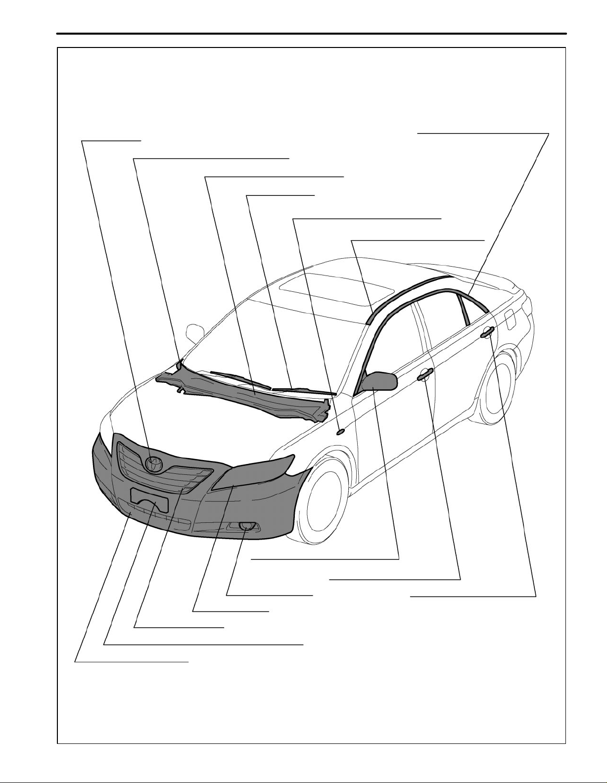
INTRODUCTION
IN-13
Emblem (AES)
Front Fender To Cowl Side Seal (PP/EPDM)
Cowl Top Ventilator Louver (PP/TSOP)
Wiper Blade (PBT)
Ex. U.S.A:
Door Window Frame Moulding (PP)
Side Turn
Signal Light (ABS/PMMA)
Roof Drip Side Finish Moulding (TPO)
Foglight (ASA/PBT)
Headlight (PC/PP)
Radiator Grille (ABS)
Front Bumper Extension Mounting Bracket (TSOP)
Front Bumper Cover (TSOP)
Outer Rear View Mirror (ABS/PA/AES)
Front Door Outside Handle (PC)
Rear Door Outside Handle (PC)
F30269
IN-14
97
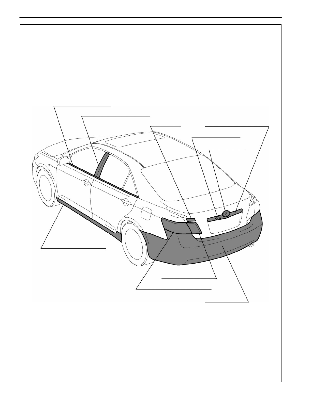
Door Belt Moulding (POM/PVC)
Door Window Frame Moulding (ASA)
INTRODUCTION
Emblem (ABS)
Luggage Compartment Opening
Door Outside Garnish (TSOP)
Licence Plate Light (PC)
Emblem (TSOP)
Rocker Panel Mounting (TSOP)
Rear Light (ASA/PMMA)
Rear Combination Light (ASA/PMMA)
Rear Bumper (TSOP)
F30269A
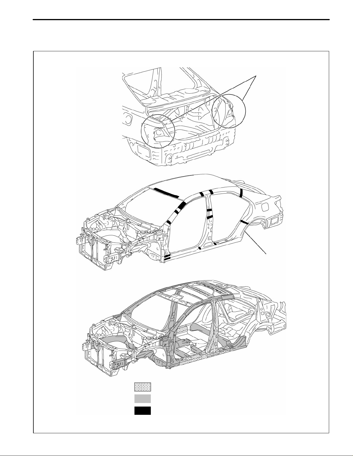
ABOUT THIS VEHICLE
STRUCTUAL OUTLINE
INTRODUCTION
IN-15
Laser welding (12points)
Adhesive Application Area
. . .
Over 590Mpa High strength steel
. . .
Over 440Mpa High strength steel
. . .
Formed material application areas (refer to PC-8)
F30267
IN-16
INTRODUCTION
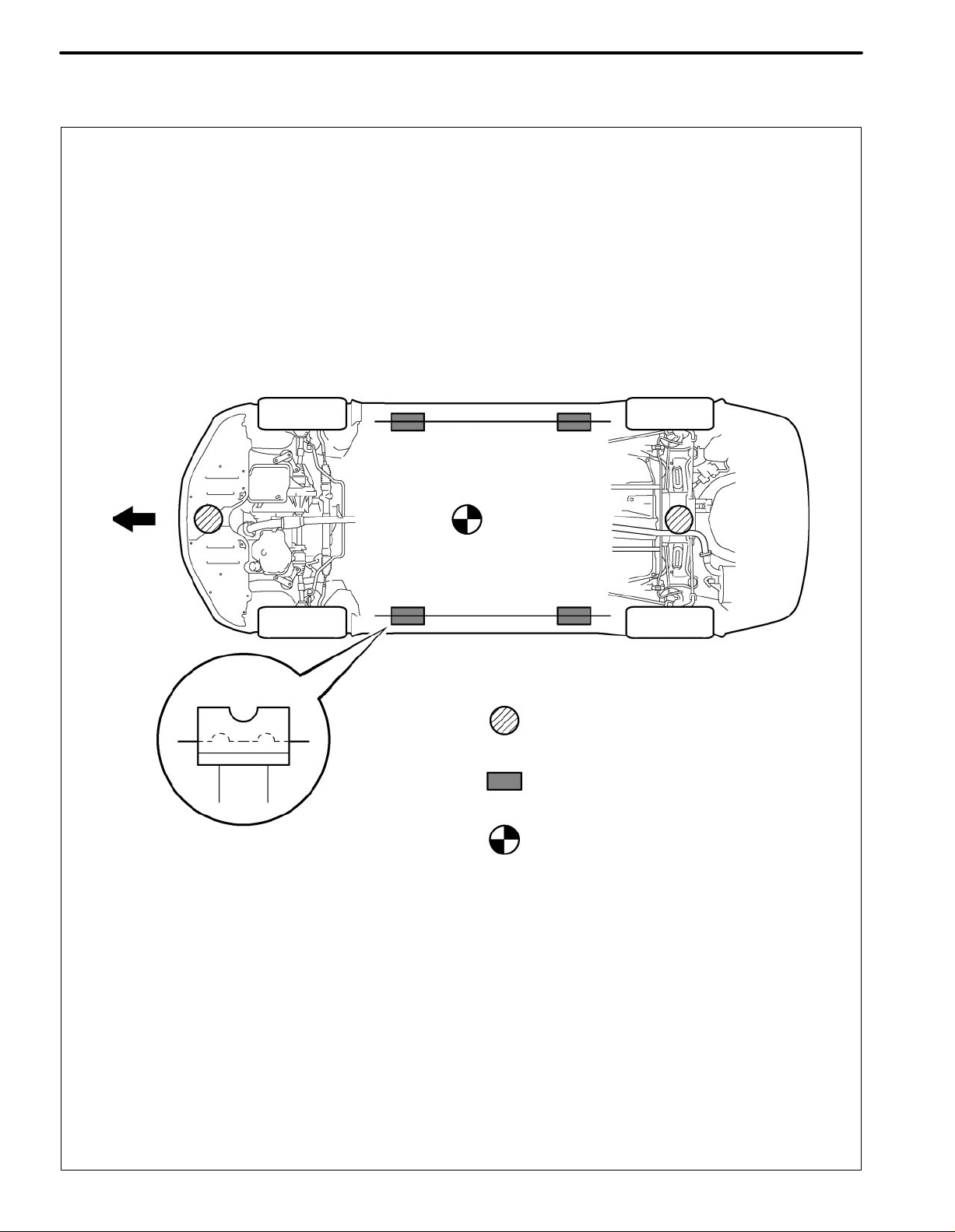
NOTICE ABOUT VEHICLE CONDITION WHEN JACKING UP VEHICLE
1. NOTICE FOR USING JACK AND SAFETY STAND
Front
: JACK POSITION
: SUPPORT POSITION,
PANTOGRAPH JACK POSITION
: CENTER OF VEHICLE GRAVITY
(unloaded condition)
D100366
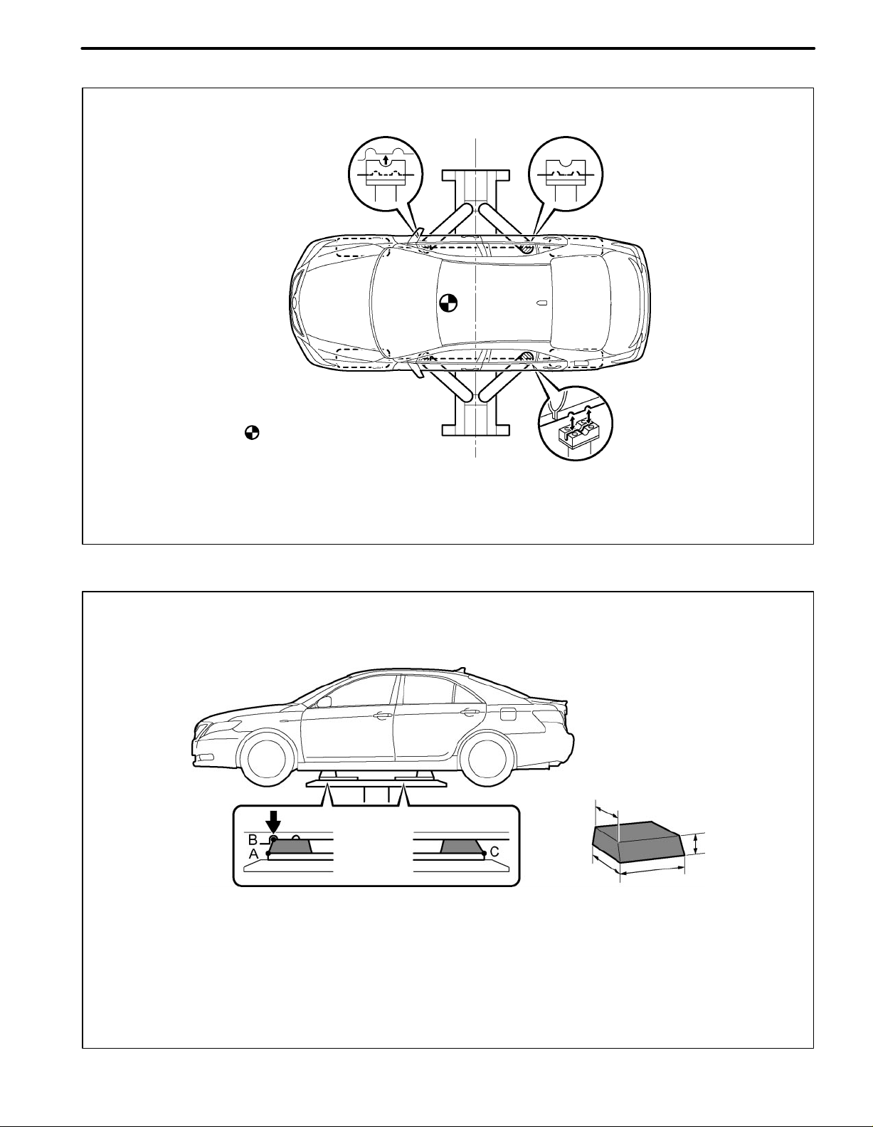
INTRODUCTION
2. NOTICE FOR USING SWING ARM TYPE LIFT
Center of Lift
CENTER OF VEHICLE
GRAVITY
(unloaded condition)
IN-17
Rubber Attachment
3. NOTICE FOR USING PLATE TYPE LIFT
Attachment
HINT:
Right and left set position
Place the vehicle over the center of the lift.
HINT:
Front and left set position
Place the attachments at the ends of the rubber plate surface, under the vehicle lift pad (A and C in the illustration).
Raise the plate slightly and reposition the vehicle so the top of the attachment (B in the illustration) is aligned with the
front side notch in the vehicle rocker flange.
Attachment Dimensions
100 mm (3.94 in.)
D100367
85 mm (3.35 in.)
70 mm
(2.76 in.)
200 mm (7.87 in.)
mm (in.)
F30268
IN-18
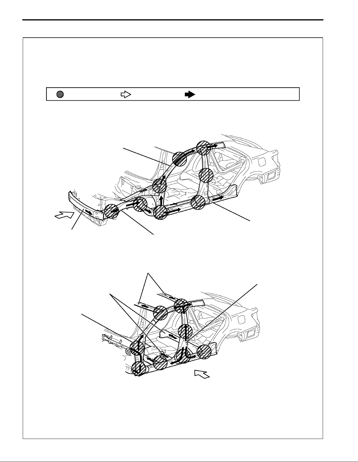
DAMAGE DIAGNOSIS
Confirmation Point Collision Direction Collision Force Absorption Direction
Front Body Pillar
Upper Reinforcement
INTRODUCTION
Front Bumper
Reinforcement
Front Body Pillar
Reinforcement
Rocker Panel Reinforecement
Front Side Member
Roof Reinforcement
Center Pillar Reinforcement
Floor Cross Member
F30266
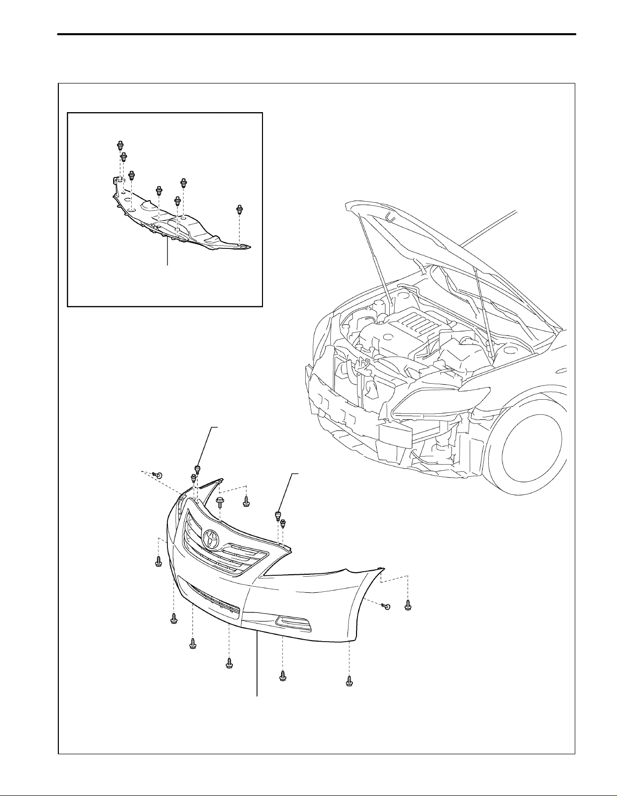
COMPORNENTS
1. Front bumper
for 2GR-FE:
COOL AIR IN TAKE DUCT SEAL
INTRODUCTION
IN-19
RADIATOR GRILLE
PROTECTOR
RADIATOR GRILLE
PROTECTOR
FRONT BUMPER ASSEMBLY
B137228
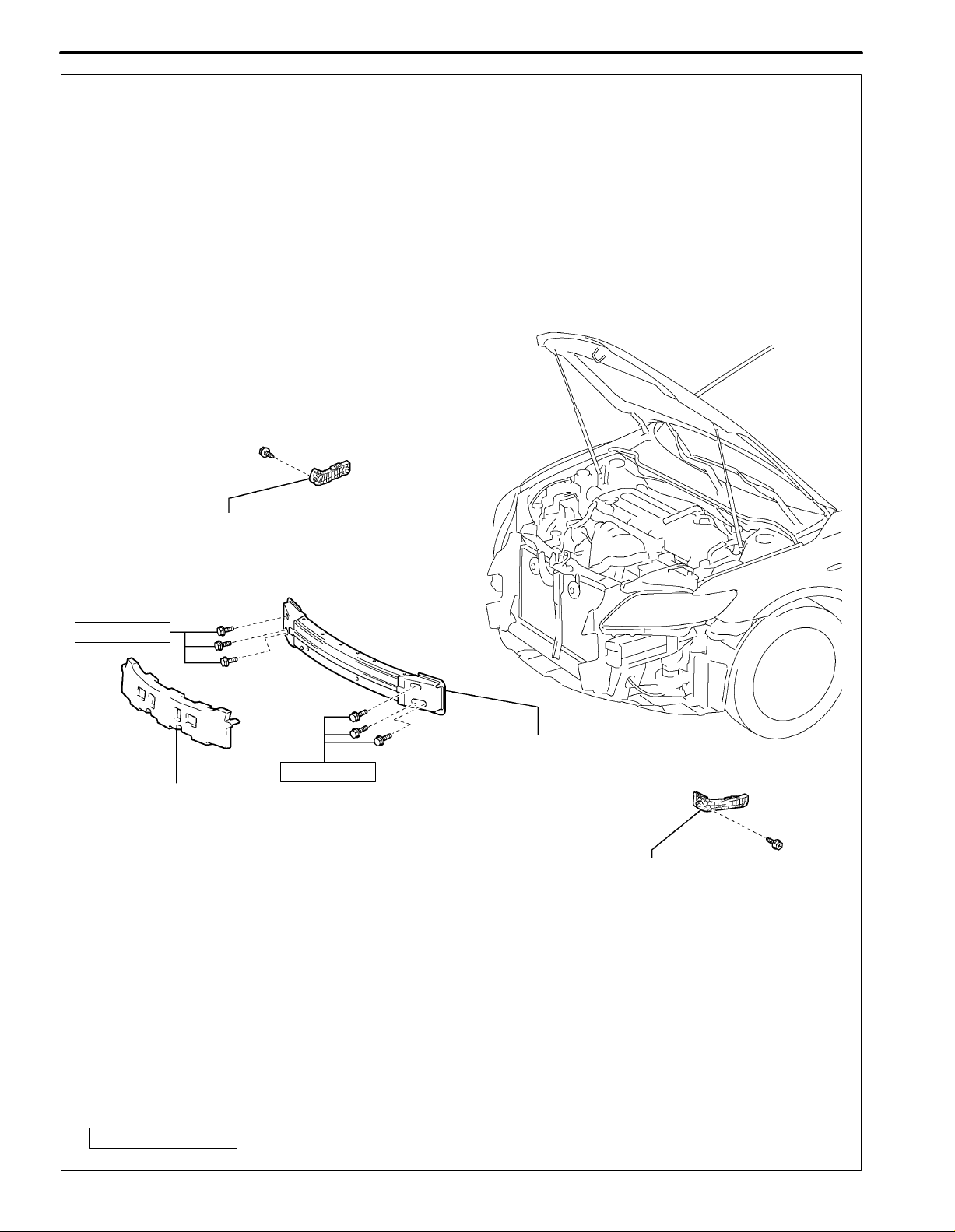
IN-20
INTRODUCTION
FRONT BUMPER
SIDE RETAINER RH
34 (347, 25)
FRONT BUMPER
ENERGY ABSORBER
34 (347, 25)
FRONT BUMPER REINFORCEMENT
SUB-ASSEMBLY
FRONT BUMPER
SIDE RETAINER LH
CAUTION:
The bolts and nuts must be tightened to the torque specification, as they are related to vehicle safety during a collision.
N.m (kgf.cm, ft..lbf)
: Specified torque
B137743
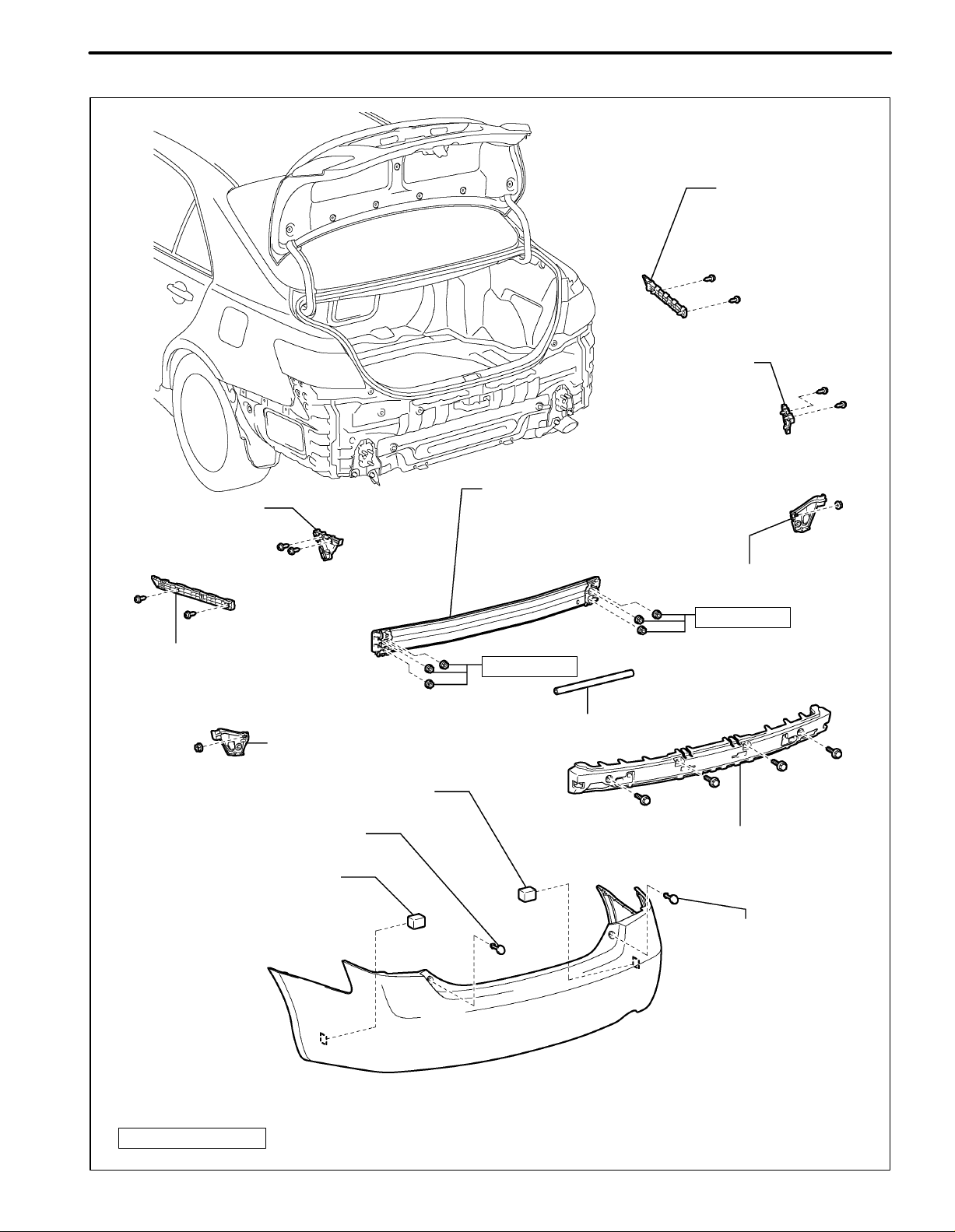
2. Rear bumper
REAR BUMPER
SIDE RETAINER LH
INTRODUCTION
REAR BUMPER REINFORCEMENT
SUB-ASSEMBLY
IN-21
REAR BUMPER
SIDE SUPPORT RH
REAR BUMPER
SIDE RETAINER RH
REAR BUMPER
SIDE SUPPORT LH
REAR BUMPER PLATE LH
REAR BUMPER PAD
WHEEL HOUSE REINFORCEMENT RH
68 (693, 50)
68 (693, 50)
REAR BUMPER BAR
WHEEL HOUSE REINFORCEMENT LH
REAR BUMPER PAD
REAR BUMPER ENERGY ABSORBER
REAR BUMPER PLATE RH
CAUTION:
The bolts and nuts must be tightened to the torque specification, as they are related to vehicle safety during a collision.
N.m (kgf.cm, ft..lbf)
: Specified torque
B137225
IN-22
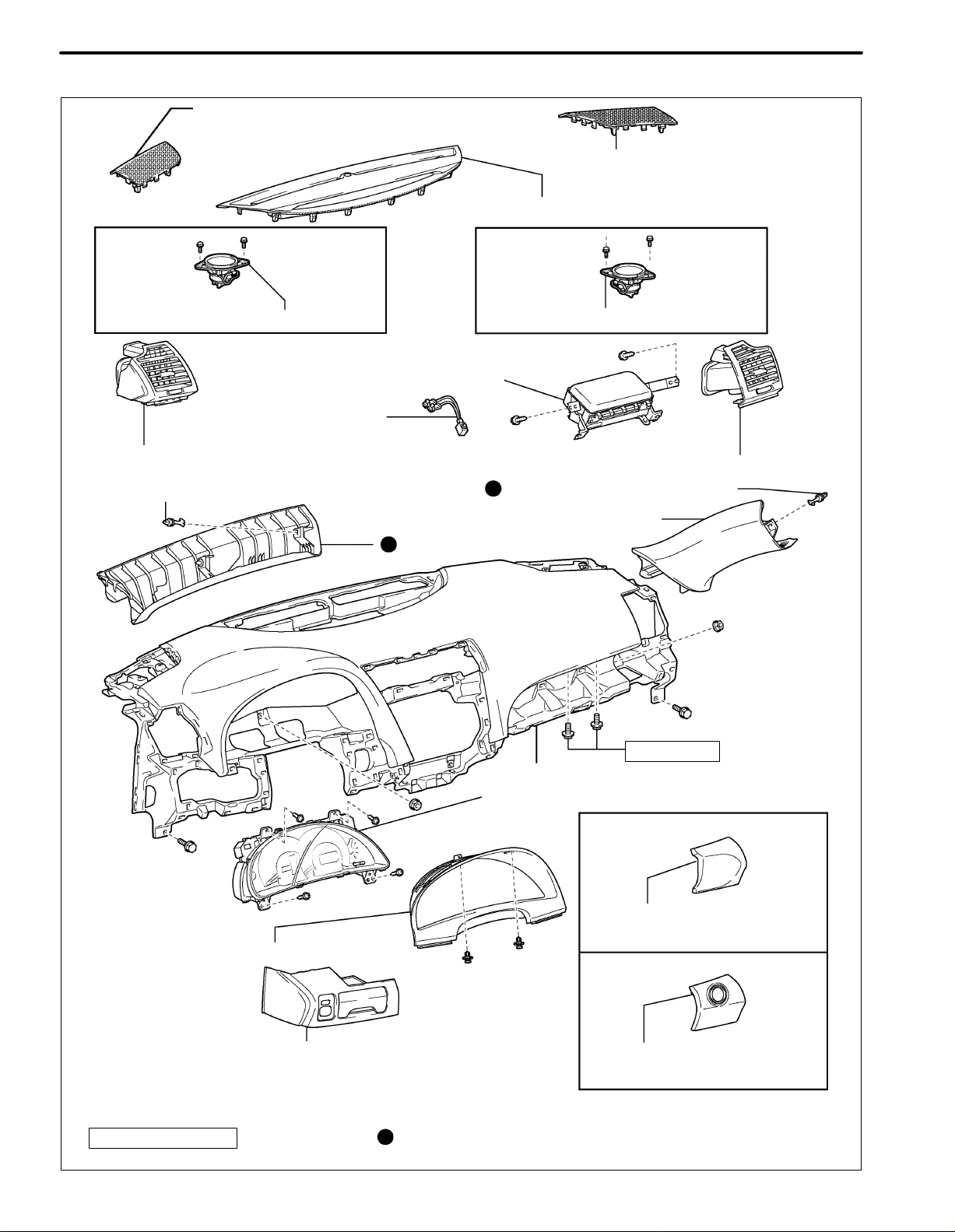
INTRODUCTION
3. Instrument panel
INSTRUMENT PANEL NO. 1
SPEAKER PANEL SUB-ASSEMBLY
for LH Side: for RH Side:
FRONT NO. 2 SPEAKER ASSEMBLY FRONT NO. 2 SPEAKER ASSEMBLY
FRONT PASSENGER
AIRBAG ASSEMBLY
INSTRUMENT PANEL
WIRE ASSEMBLY
INSTRUMENT PANEL NO. 2
SPEAKER PANEL SUB-ASSEMBLY
NO. 1 DEFROSTER NOZZLE GARNISH
INSTRUMENT PANEL NO. 1 REGISTER ASSEMBLY
FRONT PILLAR GARNISH CLIP
INSTRUMENT PANEL NO. 3 REGISTER ASSEMBLY
FRONT PILLAR GARNISH CLIP
FRONT PILLAR GARNISH RH
FRONT PILLAR GARNISH LH
20 (204, 15)
INSTRUMENT PANEL SAFETY PAD ASSEMBLY
COMBINATION METER ASSEMBLY
without Smart Key System:
LOWER INSTRUMENT PANEL
FINISH PANEL
INSTRUMENT CLUSTER FINISH PANEL
NO. 1 INSTRUMENT PANEL SUB-ASSEMBLY
CAUTION:
The bolts and nuts must be tightened to the torque specification, as they are related to vehicle safety during a collision.
N.m (kgf.cm, ft..lbf)
: Specified torque
Non-reusable part
with Smart Key System:
LOWER INSTRUMENT PANEL
FINISH PANEL
B137286
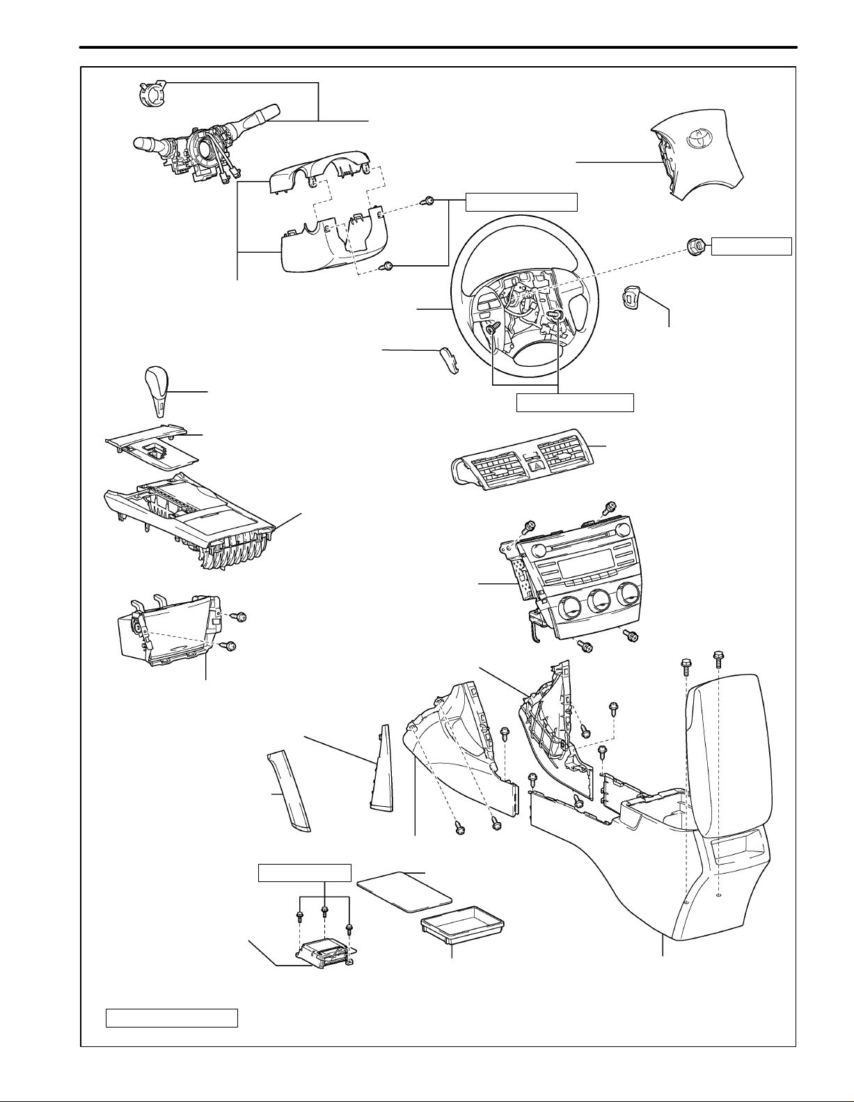
STEERING COLUMN COVER
STEERING WHEEL ASSEMBLY
INTRODUCTION
TURN SIGNAL SWITCH ASSEMBLY
WITH SPIRAL CABLE SUB-ASSEMBLY
STEERING PAD
2.0 (20, 18 in..lbf)
IN-23
50 (510, 37)
LOWER NO. 3 STEERING
WHEEL COVER
SHIFT LEVER KNOB
SUB-ASSEMBLY
FLOOR SHIFT POSITION
INDICATOR HOUSING
SUB-ASSEMBLY
UPPER CONSOLE REAR
PANEL SUB-ASSEMBLY
RADIO RECEIVER WITH HEATER
CONTROL PANEL ASSEMBLY
NO. 1 CONSOLE BOX INSERT FRONT
UPPER CONSOLE PANEL SUB-ASSEMBLY
NO. 2 INSTRUMENT CLUSTER
FINISH PANEL GARNISH
LOWER NO. 2 STEERING
WHEEL COVER
8.8 (90, 78 in..lbf)
INSTRUMENT PANEL NO. 2
REGISTER ASSEMBLY
NO. 1 INSTRUMENT
CLUSTER FINISH
PANEL GARNISH
NO. 2 CONSOLE BOX INSERT FRONT
17.5 (179, 13)
CONSOLE BOX CARPET
CENTER AIRBAG
SENSOR ASSEMBLY
CONSOLE BOX POCKET
CONSOLE BOX ASSEMBLY
CAUTION:
The bolts and nuts must be tightened to the torque specification, as they are related to vehicle safety during a collision.
N.m (kgf.cm, ft..lbf)
: Specified torque
B137285
IN-24
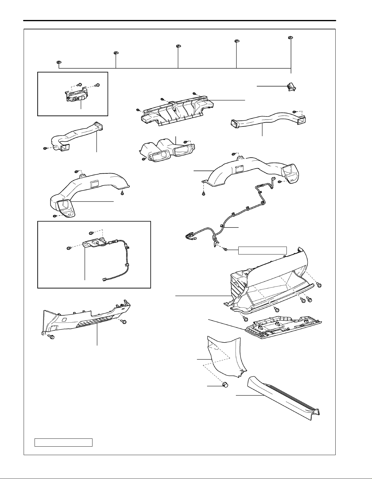
INTRODUCTION
with Plasmacluster:
PLASMACLUSTER
SIDE NO. 1 DEFROSTER
NOZZLE DUCT
with Navigation System:
NO. 3 INSTRUMENT PANEL STAY
GLOVE BOX LIGHT ASSEMBLY
DEFROSTER NOZZLE
ASSEMBLY
NO. 2 HEATER TO REGISTER DUCT
SIDE NO. 2 DEFROSTER
NOZZLE DUCT
NO. 3 HEATER TO
REGISTER DUCT
NO. 1 HEATER TO REGISTER DUCT
NO. 2 ANTENNA CORD
SUB-ASSEMBLY
7.0 (71, 62 in..lbf)
NAVIGATION ANTENNA ASSEMBLY
LOWER INSTRUMENT PANEL SUB-ASSEMBLY
INSTRUMENT PANEL NO. 2
UNDER COVER SUB-ASSEMBLY
LOWER INSTRUMENT PANEL FINISH PANEL LH
COWL SIDE TRIM SUB-ASSEMBLY RH
COWL SIDE TRIM CLIP
FRONT DOOR SCUFF PLATE RH
CAUTION:
The bolts and nuts must be tightened to the torque specification, as they are related to vehicle safety during a collision.
N.m (kgf.cm, ft..lbf)
: Specified torque
B137288
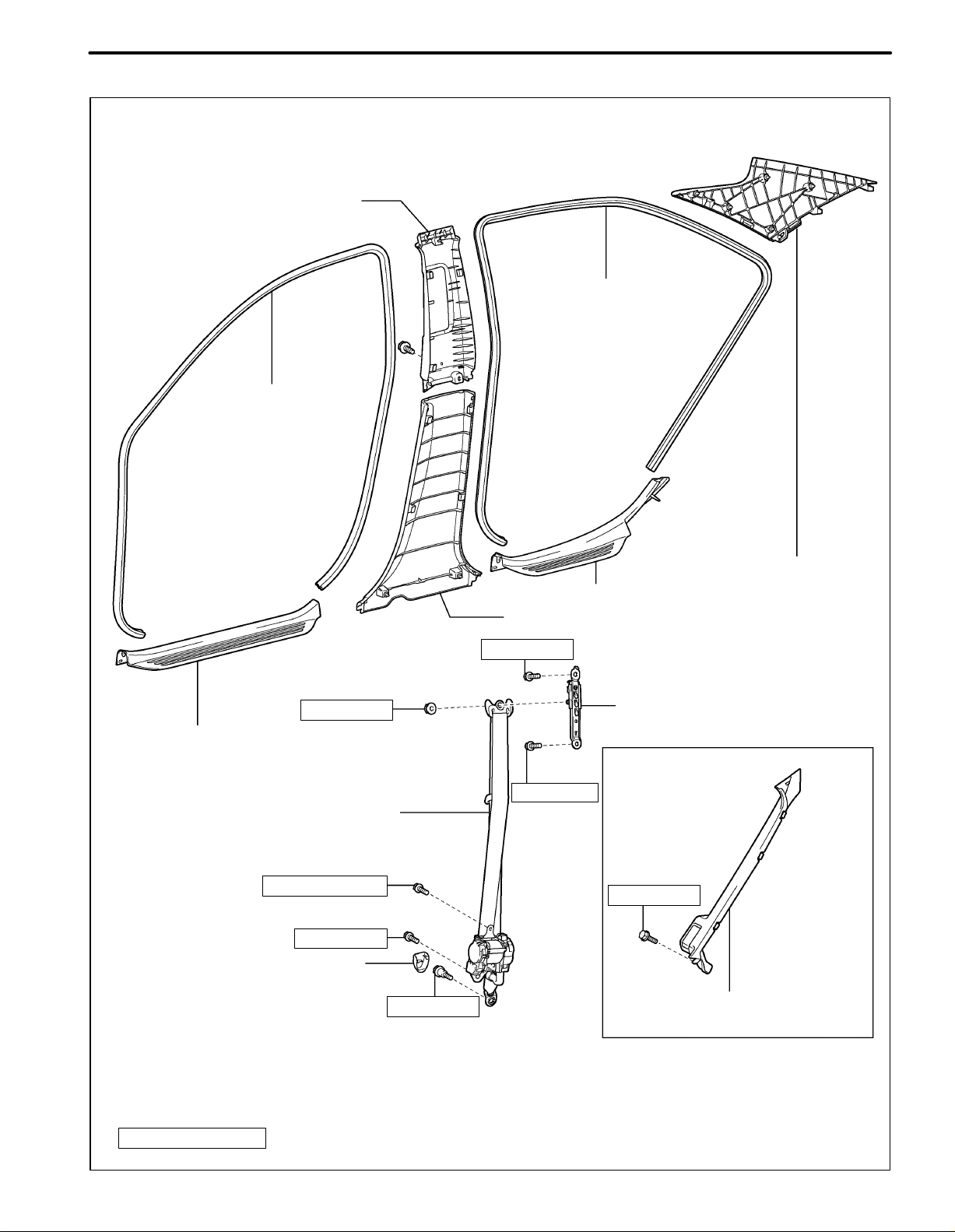
4. Interior trim
UPPER CENTER PILLAR GARNISH
FRONT DOOR OPENING
TRIM WEATHERSTRIP
INTRODUCTION
REAR DOOR OPENING
TRIM WEATHERSTRIP
IN-25
42 (428, 31)
FRONT DOOR SCUFF PLATE
FRONT SEAT OUTER BELT ASSEMBLY
7.5 (77, 66 in..lbf)
42 (428, 31)
LAP BELT OUTER ANCHOR COVER
42 (428, 31)
ROOF SIDE INNER GARNISH LH
REAR DOOR SCUFF PLATE
LOWER CENTER PILLAR GARNISH
42 (428, 31)
FRONT SHOULDER BELT ANCHOR
ADJUSTER ASSEMBLY
for Reclining Seat Type:
42 (428, 31)
18 (184, 13)
RECLINING REMOTE CONTROL
LEVER SUB-ASSEMBLY LH
CAUTION:
The bolts and nuts must be tightened to the torque specification, as they are related to vehicle safety during a collision.
N.m (kgf.cm, ft..lbf)
: Specified torque
B132005
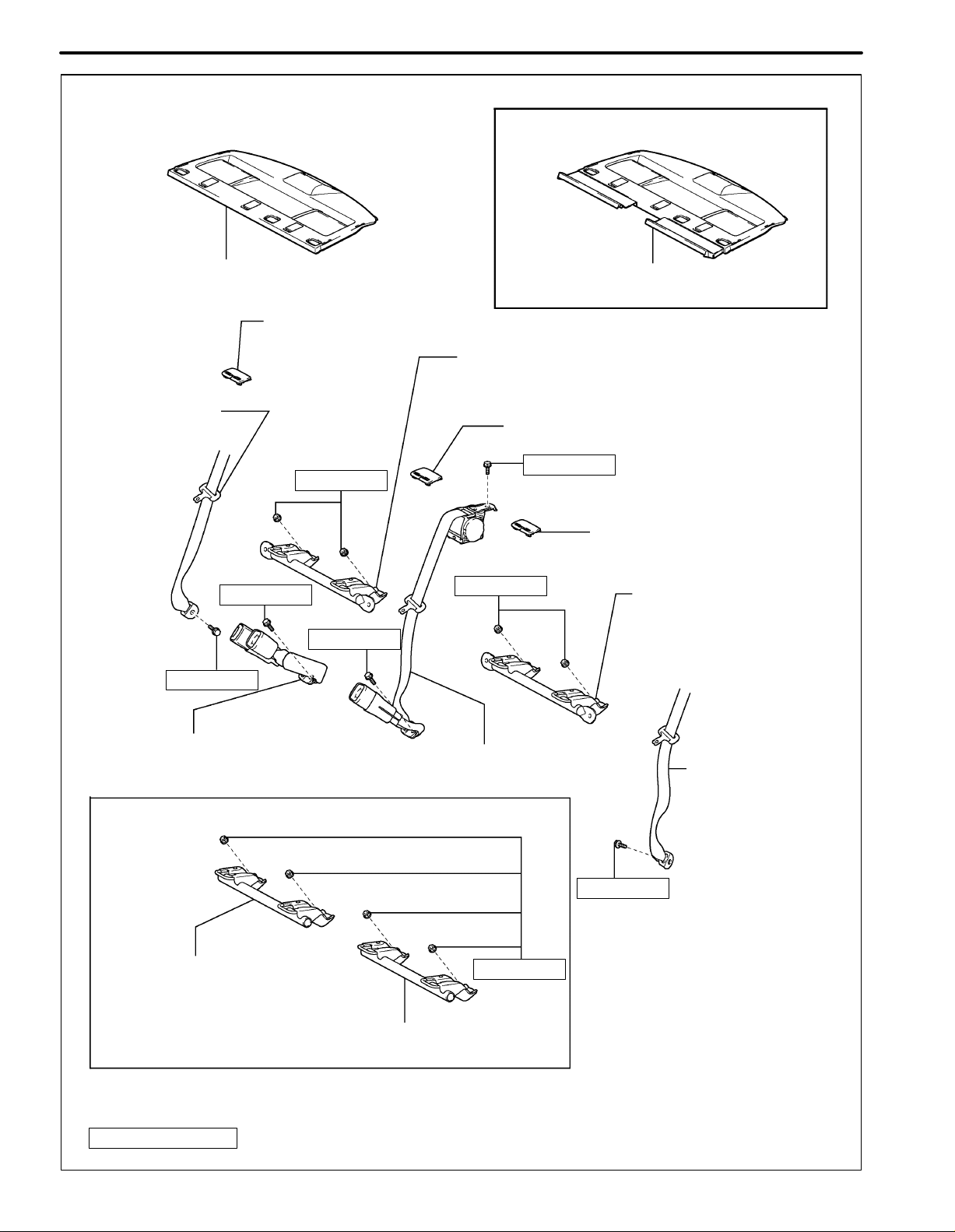
IN-26
INTRODUCTION
for Reclining Seat Type:
PACKAGE TRAY TRIM PANEL ASSEMBLY
REAR SEAT SHOULDER BELT COVER
REAR SEAT OUTER
BELT ASSEMBLY
18 (184, 13)
42 (428, 31)
42 (428, 31)
42 (428, 31)
PACKAGE TRAY TRIM PANEL ASSEMBLY
CHILD RESTRAINT SEAT ANCHOR
BRACKET SUB-ASSEMBLY RH
REAR SEAT SHOULDER BELT COVER
42 (428, 31)
REAR SEAT SHOULDER
BELT HOLE COVER
18 (184, 13)
CHILD RESTRAINT SEAT
ANCHOR BRACKET
SUB-ASSEMBLY LH
REAR SEAT INNER WITH
CENTER BELT ASSEMBLY RH
REAR SEAT INNER WITH
CENTER BELT ASSEMBLY LH
REAR SEAT OUTER
BELT ASSEMBLY
for Fold Down Seat Type:
42 (428, 31)
CHILD RESTRAINT SEAT ANCHOR
18 (184, 13)
BRACKET SUB-ASSEMBLY RH
CHILD RESTRAINT SEAT ANCHOR
BRACKET SUB-ASSEMBLY LH
CAUTION:
The bolts and nuts must be tightened to the torque specification, as they are related to vehicle safety during a collision.
N.m (kgf.cm, ft..lbf)
: Specified torque
B132019
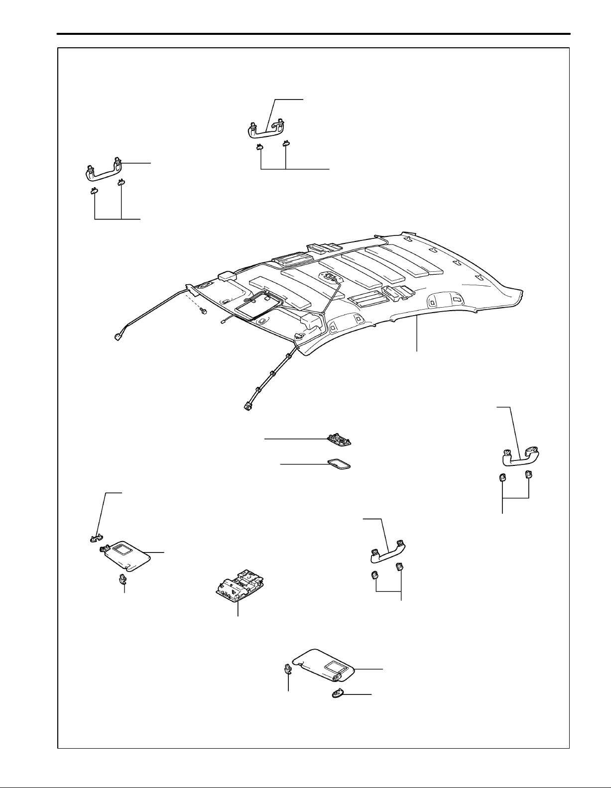
without Sliding Roof:
INTRODUCTION
REAR ASSIST GRIP SUB-ASSEMBLY
IN-27
FRONT ASSIST GRIP
SUB-ASSEMBLY
ASSIST GRIP COVER
NO. 1 ROOM LIGHT ASSEMBLY
ASSIST GRIP COVER
ROOF HEADLINING ASSEMBLY
REAR ASSIST GRIP SUB-ASSEMBLY
VISOR BRACKET COVER
VISOR HOLDER
ROOF CONSOLE BOX ASSEMBLY
LENS COVER
FRONT ASSIST GRIP SUB-ASSEMBLY
VISOR ASSEMBLY RH
VISOR HOLDER
ASSIST GRIP COVER
ASSIST GRIP COVER
VISOR ASSEMBLY LH
VISOR BRACKET COVER
B132051
IN-28
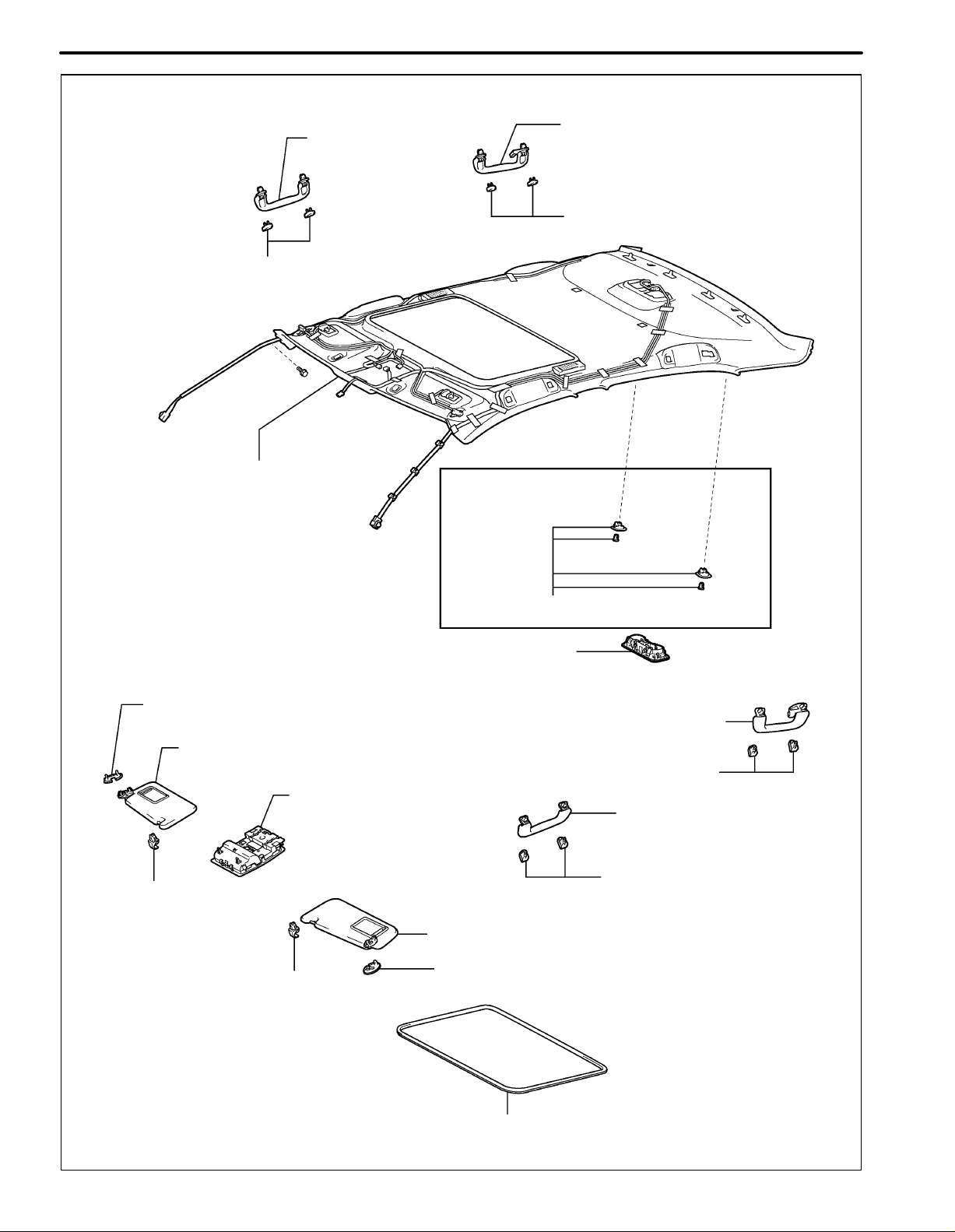
with Sliding Roof:
FRONT ASSIST GRIP
SUB-ASSEMBLY
ASSIST GRIP COVER
INTRODUCTION
REAR ASSIST GRIP
SUB-ASSEMBLY
ASSIST GRIP COVER
ROOF HEADLINING ASSEMBLY
VISOR BRACKET COVER
VISOR ASSEMBLY RH
VISOR HOLDER
ROOF CONSOLE
BOX ASSEMBLY
with Rear Sunshade:
SUNSHADE TRIM HOLDER
SPOT LIGHT ASSEMBLY
REAR ASSIST GRIP SUB-ASSEMBLY
ASSIST GRIP COVER
FRONT ASSIST GRIP
SUB-ASSEMBLY
ASSIST GRIP COVER
VISOR HOLDER
VISOR ASSEMBLY LH
VISOR BRACKET COVER
SUN ROOF OPENING TRIM MOULDING
B132052
 Loading...