

Toyota Camry 2007-2009 Service Manual - SRS

SUPPLEMENTAL RESTRAINT SYSTEM – AIRBAG SYSTEM
AIRBAG SYSTEM
PRECAUTION
CAUTION:
• The vehicle is equipped with a Supplemental Restraint
System (SRS). It consists of a driver airbag, front
passenger airbag, driver side knee airbag, side airbag,
curtain shield airbag, and front seat belt pretensioner.
Failure to carry out service operations in the correct
sequence could cause the SRS to unexpectedly
deploy during servicing, possibly leading to a serious
accident. Further , if a mistake is made in servicing the
SRS, it is possible that the SRS may fail to operate
when required. Before performing servicing (including
removal or installation of parts, inspection or
replacement), be sure to read the following items
carefully , then foll ow the correct procedures indicate d
in the repair manual.
• Wait at least 90 seconds after the ignition switch is
turned off and the negative (-) terminal cable is
disconnected from the battery before starting the
operation.
(The SRS is equipped with a backup power source, so
if work is started within 90 seconds after
disconnecting the negative (-) terminal cable from the
battery, the SRS may be deployed.)
• Do not expose the steering pad, front passenger
airbag assembly, driver side knee airbag assembly,
center airbag sensor assembly, front airbag sensor,
front seat inner belt assembly, seat position airbag
sensor, occupant classification ECU, front seat side
airbag assembly, side airbag sensor, curtain shield
airbag assembly, rear airbag sensor, or front seat
outer belt assembly directly to hot air or flames.
NOTICE:
• Malfunction symptoms of the SRS are difficult to
confirm, so DTCs are the most important source of
information when troubleshooting. When
troubleshooting the SRS, always inspect DTCs before
disconnecting the battery.
• Even in the case of a minor collision when the SRS
does not deploy, the steering pad, front passenger
airbag assembly, driver side knee airbag assembly,
center airbag sensor assembly, front airbag sensor,
front seat inner belt assembly, seat position airbag
sensor, occupant classification ECU, front seat side
airbag assembly, side airbag sensor, curtain shield
airbag assembly, rear airbag sensor, or front seat
outer belt assembly should be inspected.
• Before repair work, remove the airbag sensor if any
kind of shock is likely to occur to the airbag sensor
during the operation.
• Never use SRS parts from another vehicle. When
replacing parts, replace them with new ones.
RS–1
RS

RS
RS–2
SUPPLEMENTAL RESTRAINT SYSTEM – AIRBAG SYSTEM
• Never disassemble or repair any of the following p art s
in order to reuse them. If any of these parts have been
dropped, or a defect is found (e.g. cracks, dents or any
other defects) in any of the housings, brackets or
connectors, then replace the part with a new one.
(a)Steering Pad
(b)Front Passenger Airbag Assembly
(c)Driver Side Knee Airbag Assembly
(d)Front Seat Side Airbag Assembly
(e)Curtain Shield Airbag Assembly
(f) Center Airbag Sensor Assembly
(g)Front Airbag Sensor
(h)Front Seat Inner Belt Assembly
(i) Seat Position Airbag Sensor
(j) Occupant Classification ECU
(k)Side Airbag Sensor
(l) Rear Airbag Sensor
(m)Front Seat Outer Belt Assembly
• Use an volt/ohmmeter with high impedance (10 kΩ/V
minimum) for troubleshooting the electrical circuits.
• Information labels are attached near the SRS
components. Follow the instructions in the caution.
• After work on the SRS is completed, perform the SRS
warning light check (See page RS-32).
• When the negative (-) terminal cable is disconnected
from the battery, the memory will be cleared. Because
of this, be sure to make a record of the contents
memorized in each system before starting work. When
work is finished, adjust each system as it was before.
Never attempt to avoid erasing vehicle system
memories by using a backup power supply from
outside the vehicle.
• If the vehicle is equipped with a mobile
communication system, refer to the precaution in the
INTRODUCTION section.
HINT:
In the airbag system, the center airbag sensor assembly , front
airbag sensor LH and RH, side airbag sensor LH and RH,
and rear airbag sensor LH and RH are collectively referred to
as the airbag sensors.
1. HANDLING PRECAUTIONS FOR AIRBAG SENSORS
(a) Before starting the following operations, wait for at
least 90 seconds after disconnecting the negative () terminal cable from the battery:
(1) Replacement of the airbag sensors.
(2) Adjustment of the front/rear doors of the vehicle
equipped with the side airbag and curtain shield
airbag (fitting adjustment).
(b) When connecting or disconnecting the airbag
sensor connectors, ensure that each sensor is
installed in the vehicle.
(c) Do not use the airbag sensors which have been
dropped during the operation or transportation.
(d) Do not disassemble the airbag sensors.
SUPPLEMENTAL RESTRAINT SYSTEM – AIRBAG SYSTEM
2. INSPECTION PROCEDURE FOR VEHICLE INVOLVED
IN ACCIDENT
(a) When the airbag has not deployed, confirm the
DTCs by checking the SRS warning light. If there is
any malfunction in the SRS airbag system, perform
troubleshooting.
(b) When any of the airbags have deployed, replace the
airbag sensors and check the installation condition.
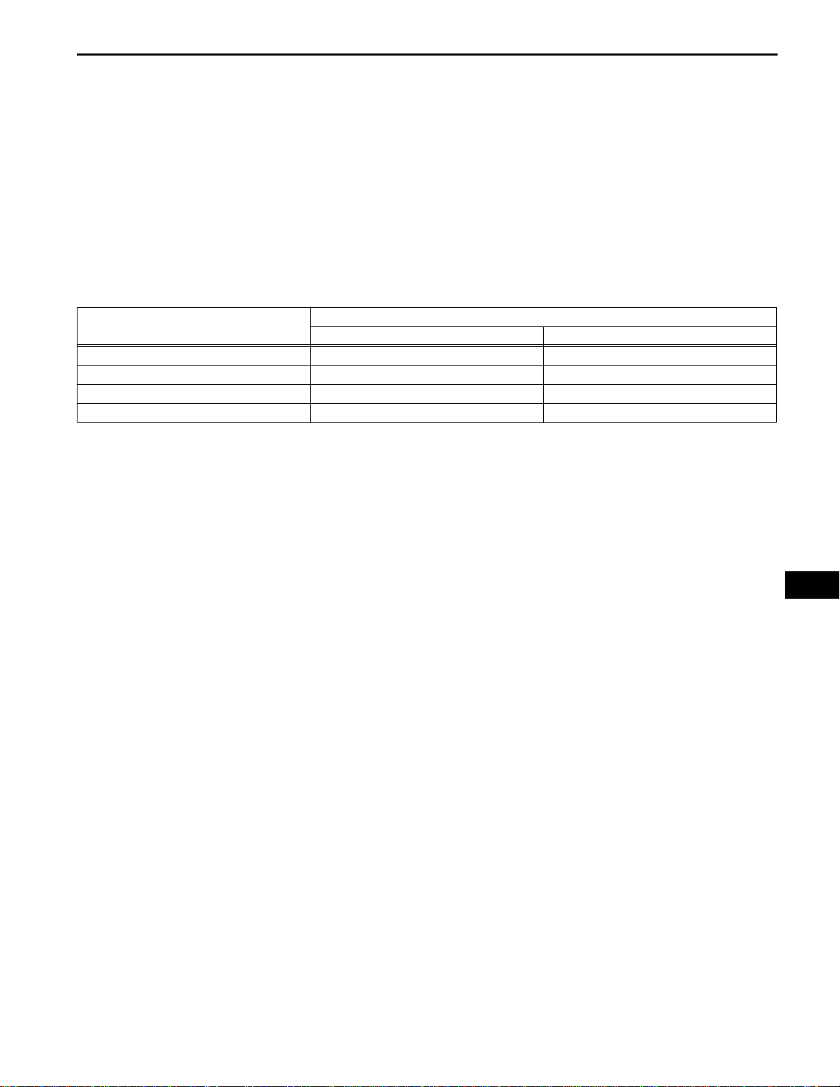
3. EXPRESSIONS OF IGNITION SWITCH
The type of ignition switch used on this model differs
according to the specifications of the vehicle.
The expressions listed in the table below are used in this
section.
Expression
Ignition Switch off LOCK Off
Ignition Switch on (IG) ON On (IG)
Ignition Switch on (ACC) ACC On (ACC)
Engine Start START Start
Ignition Switch (position) Engine Switch (condition)
Switch Type
RS–3
RS
RS–4
Driver Side:
SUPPLEMENTAL RESTRAINT SYSTEM – AIRBAG SYSTEM
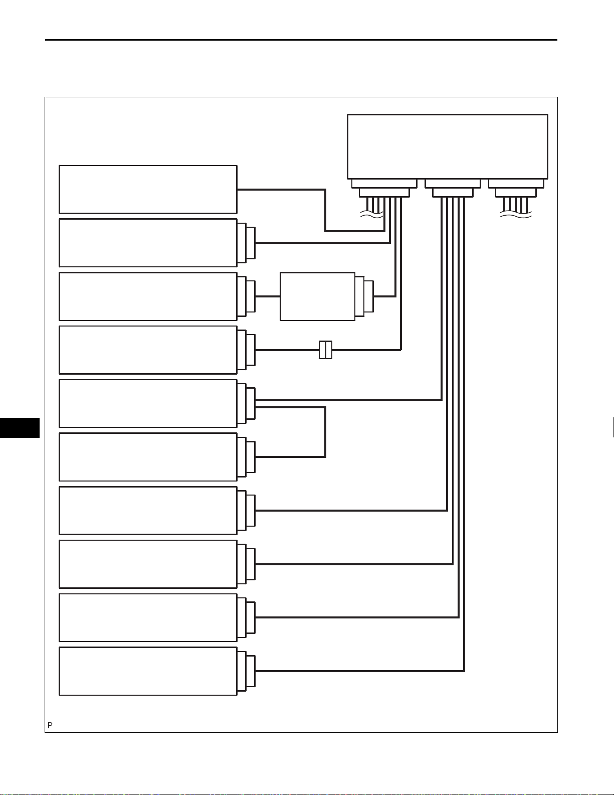
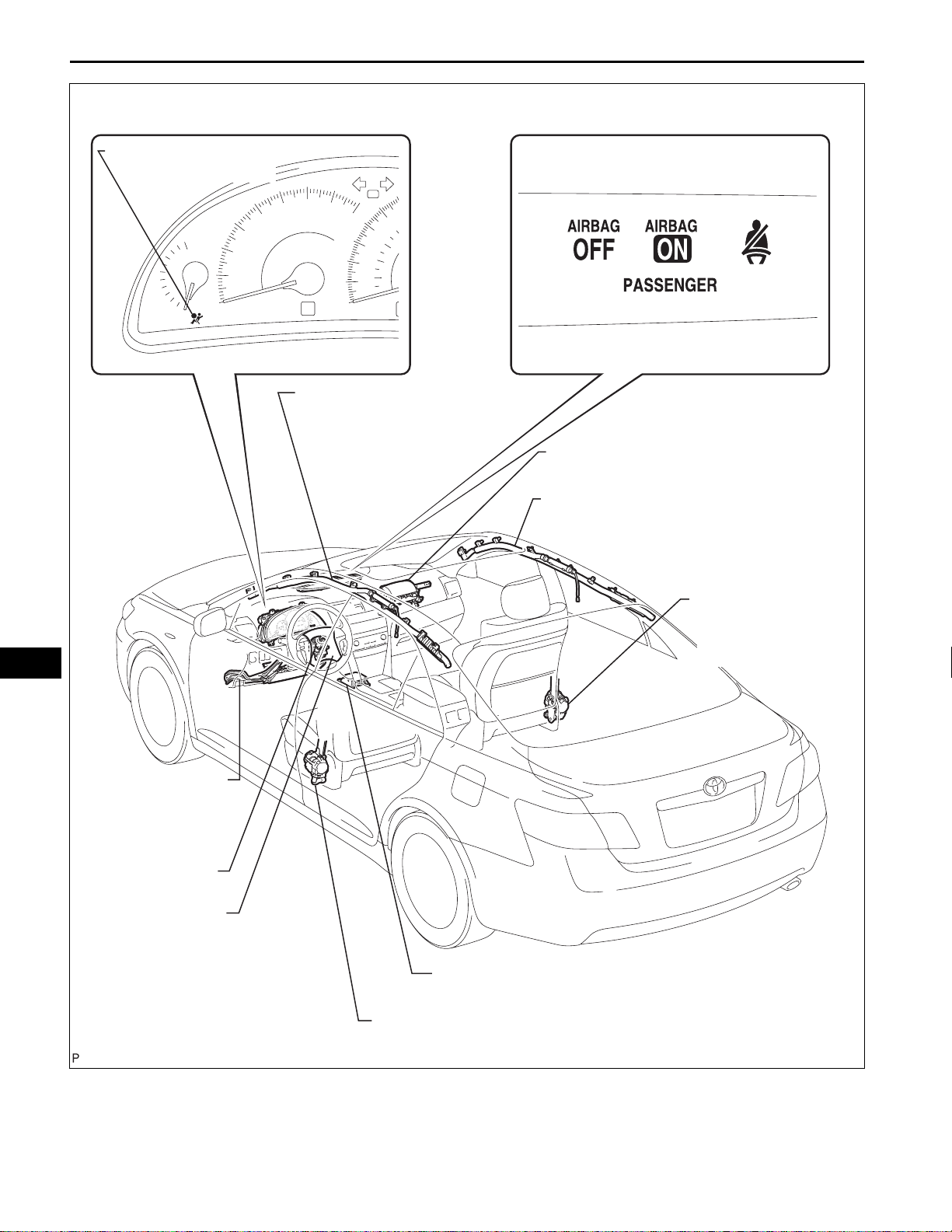
4. SRS CONNECTORS
(a) SRS connectors are located as shown in the
following illustration.
Center Airbag Sensor Assembly
RS
Combination Meter Assembly
(SRS Warning Light)
Driver Side Knee Airbag Assembly
(Driver Side Knee Airbag Squib)
Steering Pad (Driver Side Squib)
Front Airbag Sensor LH
Side Airbag Sensor LH
Rear Airbag Sensor LH
13
7
17
19
21
14
8
18
20
22
Spiral Cable
16 15
1
2
5
6
3
4
3
4
Front Seat Side Airbag Assembly LH
(Driver Side - Side Squib)
Curtain Shield Airbag Assembly LH
(Driver Side Curtain Shield Squib)
Front Seat Outer Belt Assembly LH
(Driver Side Front Pretensioner Squib)
Front Seat Inner Belt Assembly LH (Driver Side
Seat Belt Buckle Switch) / Seat Position Airbag
Sensor
23
24
25
26
27
28
29
30
C123769E01
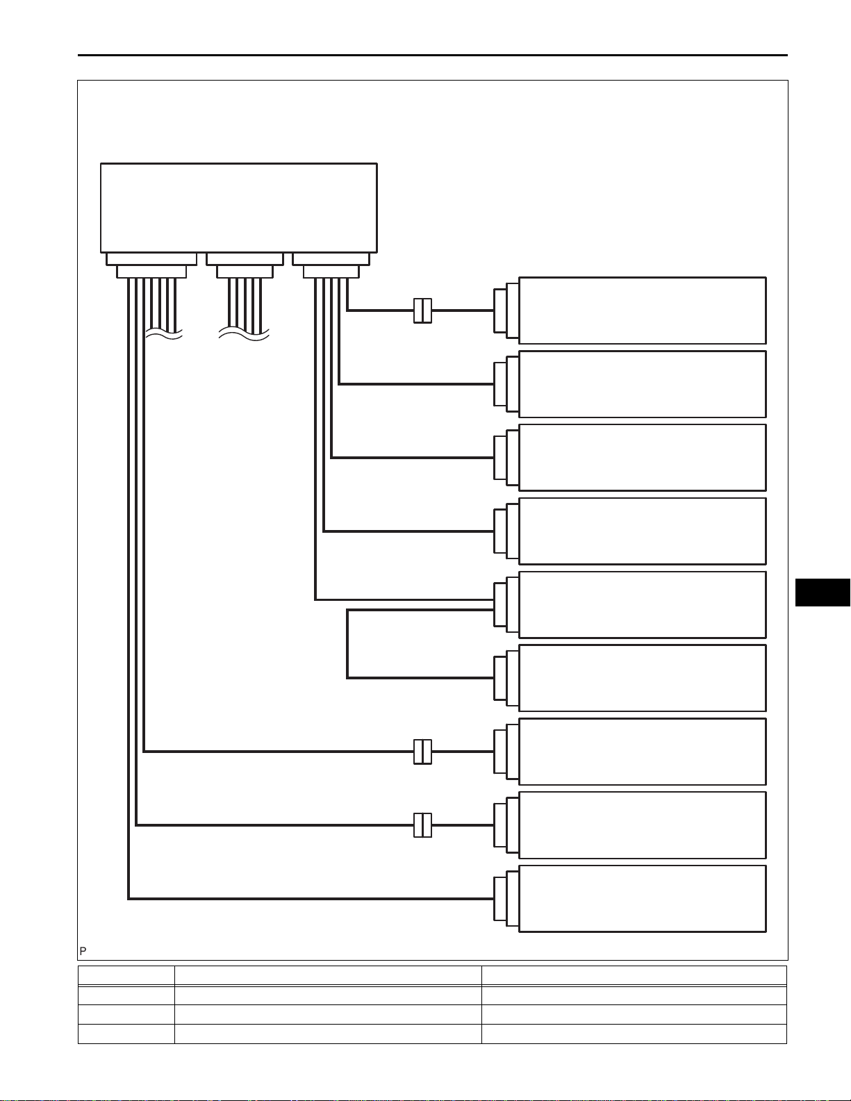
SUPPLEMENTAL RESTRAINT SYSTEM – AIRBAG SYSTEM
Passenger Side:
Center Airbag Sensor Assembly
RS–5
1
2
3
4
3
4
33
31 32
34
23
Occupant Classification ECU
Front Seat Side Airbag Assembly RH
(Front Passenger Side - Side Squib)
24
25
Curtain Shield Airbag Assembly RH (Front
Passenger Side Curtain Shield Squib)
26
29
Front Seat Outer Belt Assembly RH (Front
Passenger Side Front Pretensioner Squib)
30
19
Side Airbag Sensor RH
RS
20
21
22
Rear Airbag Sensor RH
11
109
Front Passenger Airbag Assembly
(Front Passenger Side Squib)
12
17
15 16
Front Airbag Sensor RH
18
35
Clock Assembly (Passenger Airbag
ON/OFF Indicator)
36
No. Item Application
(1) Terminal Twin-Lock Mechanism Connectors 5, 6, 9, 10, 15, 16, 20, 22, 23, 24, 31, 32
(2) Activation Prevention Mechanism Connectors 2, 4, 5, 10, 11, 13, 23, 25, 27
(3) Half Connection Prevention Mechanism Connectors 5, 6, 9, 16, 20, 22, 24
C123770E01

RS–6
No. Item Application
(4) Connector Position Assurance Mechanism Connector 18
(5) Connector Lock Mechanism (1) Connectors 8, 12, 14, 26, 28
(6) Connector Lock Mechanism (2) Connector 2, 4
(7) Improper Connection Prevention Lock Mechanism Connector 1, 3
SUPPLEMENTAL RESTRAINT SYSTEM – AIRBAG SYSTEM
(b) All connectors in the SRS, except the seat position
airbag sensor connector, are colored yellow to
distinguish them from other connectors. These
Spacer
connectors have special functions, and are specially
designed for the SRS. All SRS connectors use
durable gold-plated terminals, and are placed in the
Housing
locations shown on the previous page to ensure
high reliability.
MaleFemale
Z005953E02
(1) Terminal twin-lock mechanism:
All connectors with a terminal twin-lock
mechanism have a two-piece component
consisting of a housing and a spacer. This
design enables the terminal to be locked
securely by two locking devices (the retainer and
the lance) to prevent terminals from coming out.
RS
Housing
SUPPLEMENTAL RESTRAINT SYSTEM – AIRBAG SYSTEM
(2) Activation prevention mechanism:
All connectors with an activation prevention
mechanism contain a short spring plate. When
these connectors are disconnected, the short
spring plate creates a short circuit by
automatically connecting the positive (+) and
negative (-) terminals of the squib.
●When Connector is Connected ●When Connector is Disconnected
Short Spring Plate
Short Spring Plate
Contacting Male Terminal
RS–7
Terminal
Connectors
Locking Part
Housing
Squib
Short Spring Plate
Stopper
Locking Arm
Slider
Short Spring Plate ON
Squib
Closed Circuit
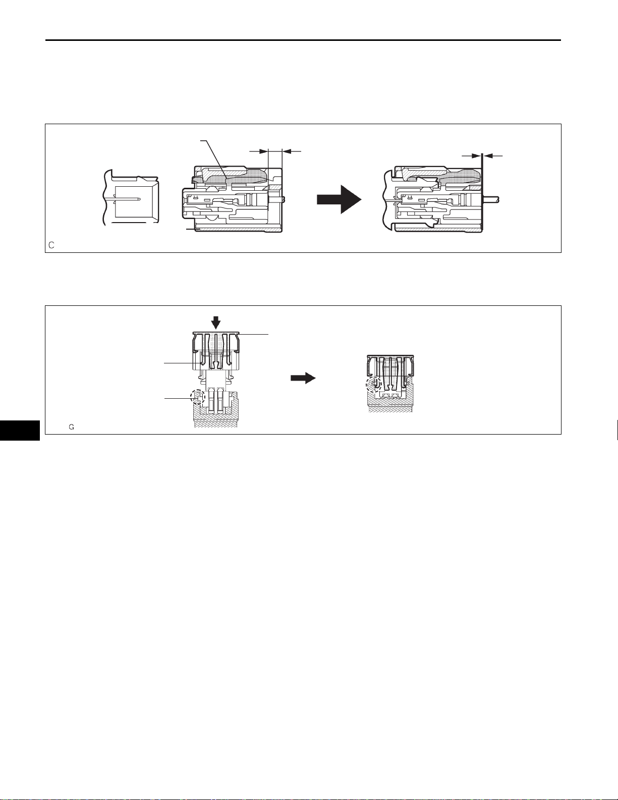
(3) Half connection prevention mechanism:
If the connector is not completely connected, the
connector is disconnected due to the spring
operation so that no continuity exists.
Spring
Rebound by Slider (Spring)
Stopper
RS
H045309E03
H040180E07
RS–8
SUPPLEMENTAL RESTRAINT SYSTEM – AIRBAG SYSTEM
(4) Connector position assurance mechanism:
Only when the housing lock (white part) is
completely engaged, the CPA (yellow part)
slides, which completes the connector
engagement.
Housing Lock (White Part)
CPA (Yellow Part)
H043306E02
(5) Connector lock mechanism (1):
Locking the connector lock button connects the
connector securely.
RS
Lock Button
Claw
Groove
H040181E04
Lance
SUPPLEMENTAL RESTRAINT SYSTEM – AIRBAG SYSTEM
(6) Connector lock mechanism (2):
Both the primary lock with holder lances and the
secondary lock with retainer prevent the
connectors from becoming disconnected.
Holder
RS–9
Retainer
Retainer
H043918E01
(7) Improper connection prevention lock
mechanism:
When connecting the holder , the lever is pushed
into the end by rotating around the A axis to lock
RS
the holder securely.
A
A
Lever
H043245E01
RS–10
SUPPLEMENTAL RESTRAINT SYSTEM – AIRBAG SYSTEM
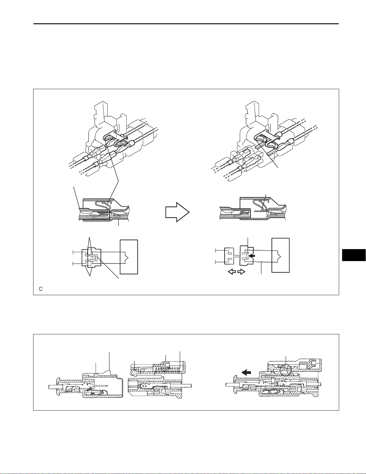
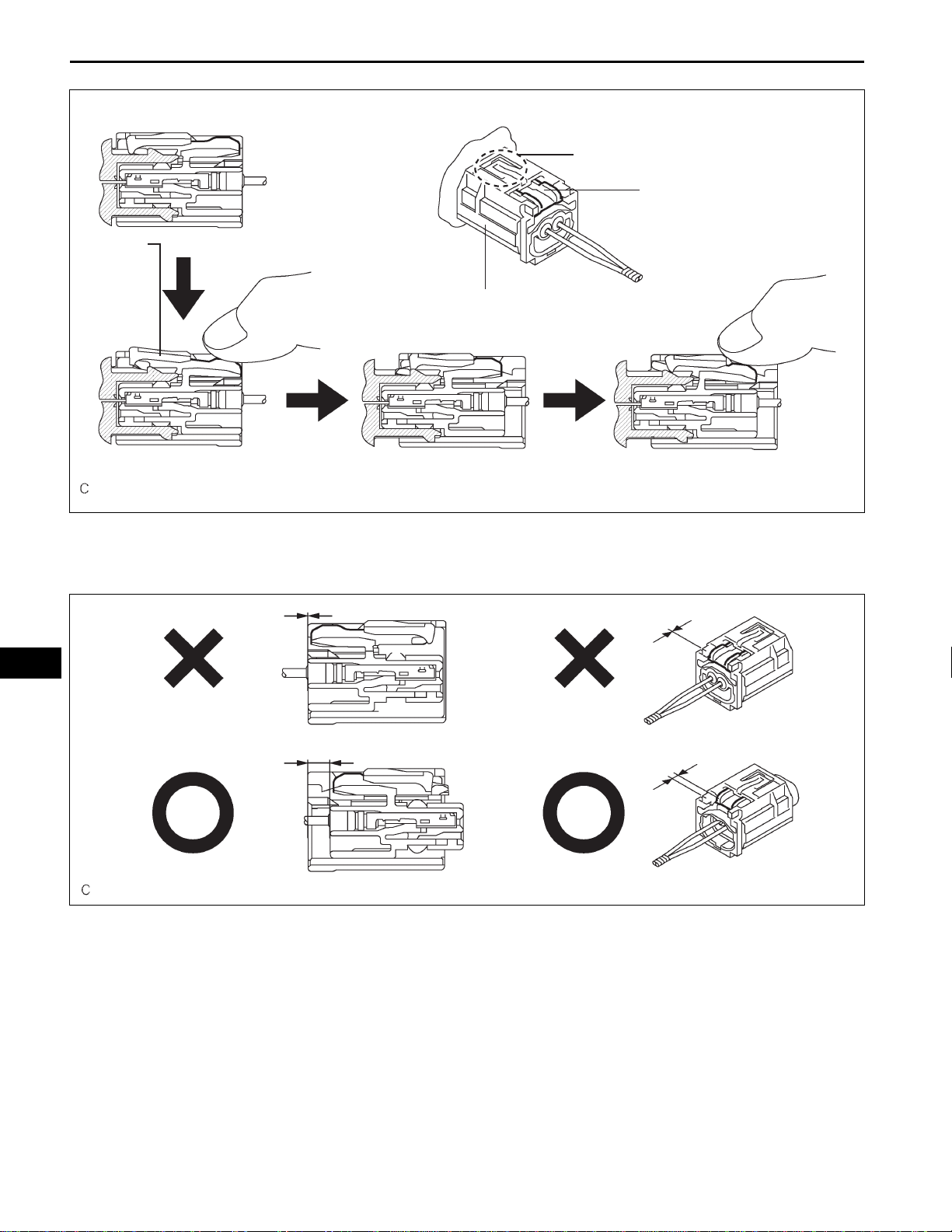
5. DISCONNECTION OF CONNECTORS FOR
STEERING PAD, FRONT PASSENGER AIRBAG
ASSEMBLY (SQUIB SIDE), DRIVER SIDE KNEE
AIRBAG ASSEMBLY, CURTAIN SHIELD AIRBAG
ASSEMBLY, AND FRONT SEAT OUTER BELT
ASSEMBLY
HINT:
Tape up the screwdriver tip before use.
(a) Release the lock button (yellow part) of the
connector using a screwdriver.
(b) Insert the screwdriver tip between the connector
and the base, and then raise the connector.
RS
Lock Button
(Yellow part)
Ta pe
Mark
C
Lock Button
(Yellow part)
C123672E01
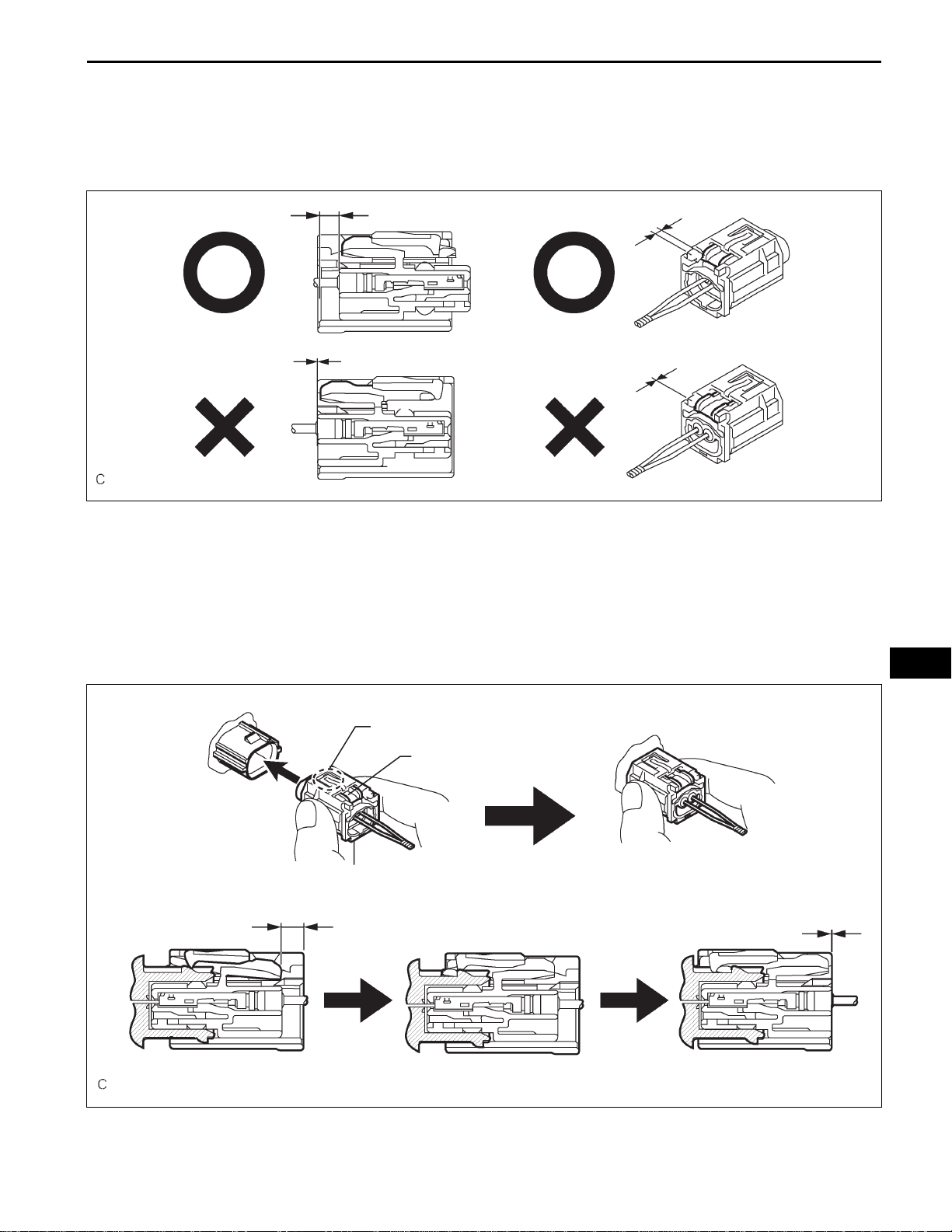
6. CONNECTION OF CONNECTORS FOR STEERING
PAD, FRONT PASSENGER AIRBAG ASSEMBLY
(SQUIB SIDE), DRIVER SIDE KNEE AIRBAG
ASSEMBLY, CURTAIN SHIELD AIRBAG ASSEMBLY,
AND FRONT SEAT OUTER BELT ASSEMBLY
(a) Connect the connector.
SUPPLEMENTAL RESTRAINT SYSTEM – AIRBAG SYSTEM
(b) Push down securely on the lock button (yellow part)
of the connector. (When locking, a click sound can
be heard.)
Lock Button
(Yellow part)
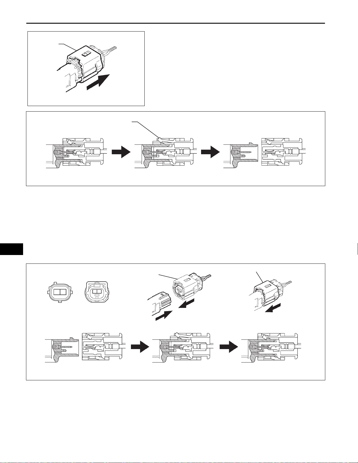
7. DISCONNECTION OF CONNECTOR FOR SPIRAL
CABLE (INSTRUMENT PANEL WIRE SIDE) AND
FRONT PASSENGER AIRBAG ASSEMBLY
(INSTRUMENT PANEL WIRE SIDE)
(a) Place a finger on the slider, slide the slider to
release the lock, and then disconnect the connector.
RS–11
H043151E04
Slider Slider
RS
Disconnection is completed
H001586E02
RS–12
SUPPLEMENTAL RESTRAINT SYSTEM – AIRBAG SYSTEM
8. CONNECTION OF CONNECTOR FOR SPIRAL CABLE
(INSTRUMENT PANEL WIRE SIDE) AND FRONT
PASSENGER AIRBAG ASSEMBLY (INSTRUMENT
PANEL WIRE SIDE)
(a) Connect the connector as shown in the illustration.
(When locking, make sure that the slider returns to
its original position and a click sound can be heard.)
HINT:
When connecting, the slider will slide. Be sure not to
touch the slider while connecting, as it may result in
an insecure fit.
Slider
Slider
RS
Slider
Connection is completed
H043731E02
9. DISCONNECTION OF CONNECTORS FOR FRONT
SEAT SIDE AIRBAG ASSEMBLY
(a) Place a finger on the slider, slide the slider to
release the lock, and then disconnect the connector.
Slider
Disconnection is completed
H001584E03
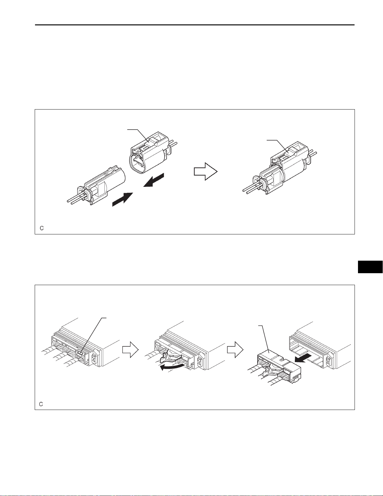
SUPPLEMENTAL RESTRAINT SYSTEM – AIRBAG SYSTEM
10. CONNECTION OF CONNECTORS FOR FRONT SEAT
SIDE AIRBAG ASSEMBLY
(a) Connect the connector as shown in the illustration.
(When locking, make sure that the slider returns to
its original position and a click sound can be heard.)
HINT:
When connecting, the slider will slide. Be sure not to
touch the slider while connecting, as it may result in
an insecure fit.
Slider
Slider
RS–13
Connection is completed
H043169E02
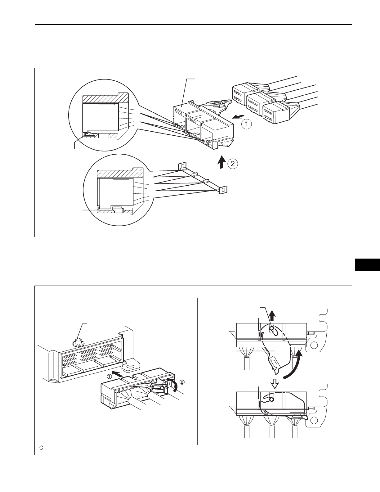
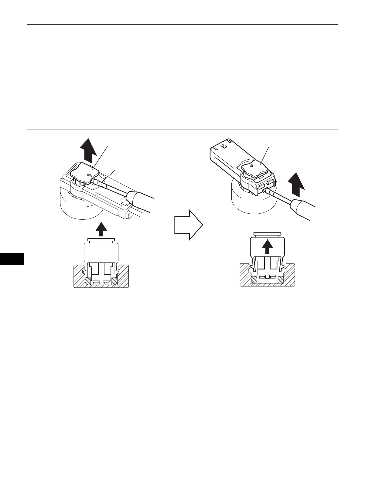
11. DISCONNECTION OF CONNECTOR FOR CENTER
AIRBAG SENSOR ASSEMBLY
(a) Pull the lever by pushing part A as shown in the
illustration and disconnect the holder (with
RS
connectors).
A
Holder (with connectors)
Disconnection is completed
H045112E01
HINT:
Perform the following procedures when replacing
the holder.
RS–14
SUPPLEMENTAL RESTRAINT SYSTEM – AIRBAG SYSTEM
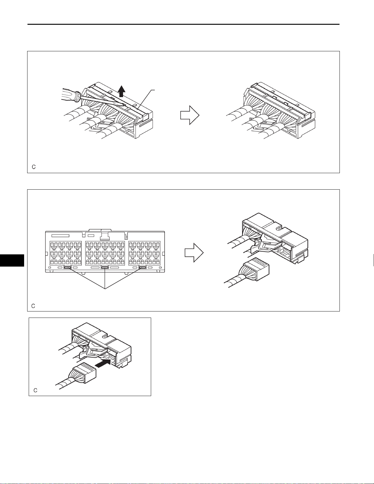
(b) Remove the holder.
(1) Using a screwdriver, unlock the retainer.
Retainer
H043188E01
(2) Release the fitting lance and remove the holder.
RS
Lances
H043190E01
H043189E01
(c) Install the holder.
(1) Install the connectors to the holder. (When
locking, a click sound can be heard.)
HINT:
The retainer is locked when the holder is
connected.
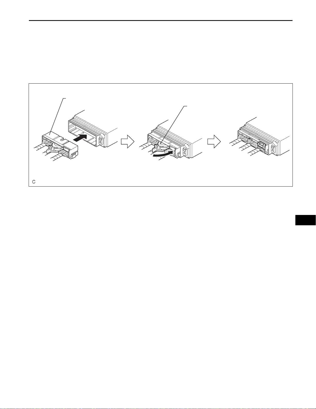
12. CONNECTION OF CONNECTOR FOR CENTER
AIRBAG SENSOR ASSEMBLY
(a) Firmly insert the holder (with connectors) into the
center airbag sensor assembly until it cannot be
pushed any further.
SUPPLEMENTAL RESTRAINT SYSTEM – AIRBAG SYSTEM
Holder (with connectors)
RS–15
(b) Push the lever to connect the holder (with
connectors). (When locking, a click sound can be
heard.)
HINT:
The holder slides into the center airbag sensor
assembly when it is being connected. Be sure not to
hold the holder while connecting, as it may result in
an insecure fit.
Lever
Connection is completed
H045113E01
13. DISCONNECTION OF CONNECTOR FOR FRONT
AIRBAG SENSOR
(a) Push down the housing lock (white part) and slide
the CPA (yellow part). (At this time, the connector
cannot be disconnected yet.)
(b) Push down the housing lock (white part) again and
disconnect the connector.
HINT:
Do not push down the A part shown in the
illustration when disconnecting.
RS
RS–16
Connector
lock is
released
SUPPLEMENTAL RESTRAINT SYSTEM – AIRBAG SYSTEM
A
Housing Lock (White Part)
CPA (Yellow Part)
RS
H043302E02
(c) After disconnecting the connector, check that the
position of the housing lock (white part) is as shown
in the illustration.
H043303E02
SUPPLEMENTAL RESTRAINT SYSTEM – AIRBAG SYSTEM
14. CONNECTION OF CONNECTOR FOR FRONT
AIRBAG SENSOR
(a) Before connecting the connectors, check that the
position of the housing lock (white part) is as shown
in the illustration.
RS–17
H043304E01
A
CPA (Yellow Part)
(b) Be sure to engage the connectors until they are
locked. (When locking, make sure that a click sound
can be heard.)
HINT:
When connecting them, the housing lock (white
part) slides. Be sure not to hold the housing lock
(white part) and A part, as it may result in an
insecure fit.
Housing Lock (White Part)
RS
Connection is completed
H043305E02
RS–18
Outer
SUPPLEMENTAL RESTRAINT SYSTEM – AIRBAG SYSTEM
H002763E02
Connector lock is released
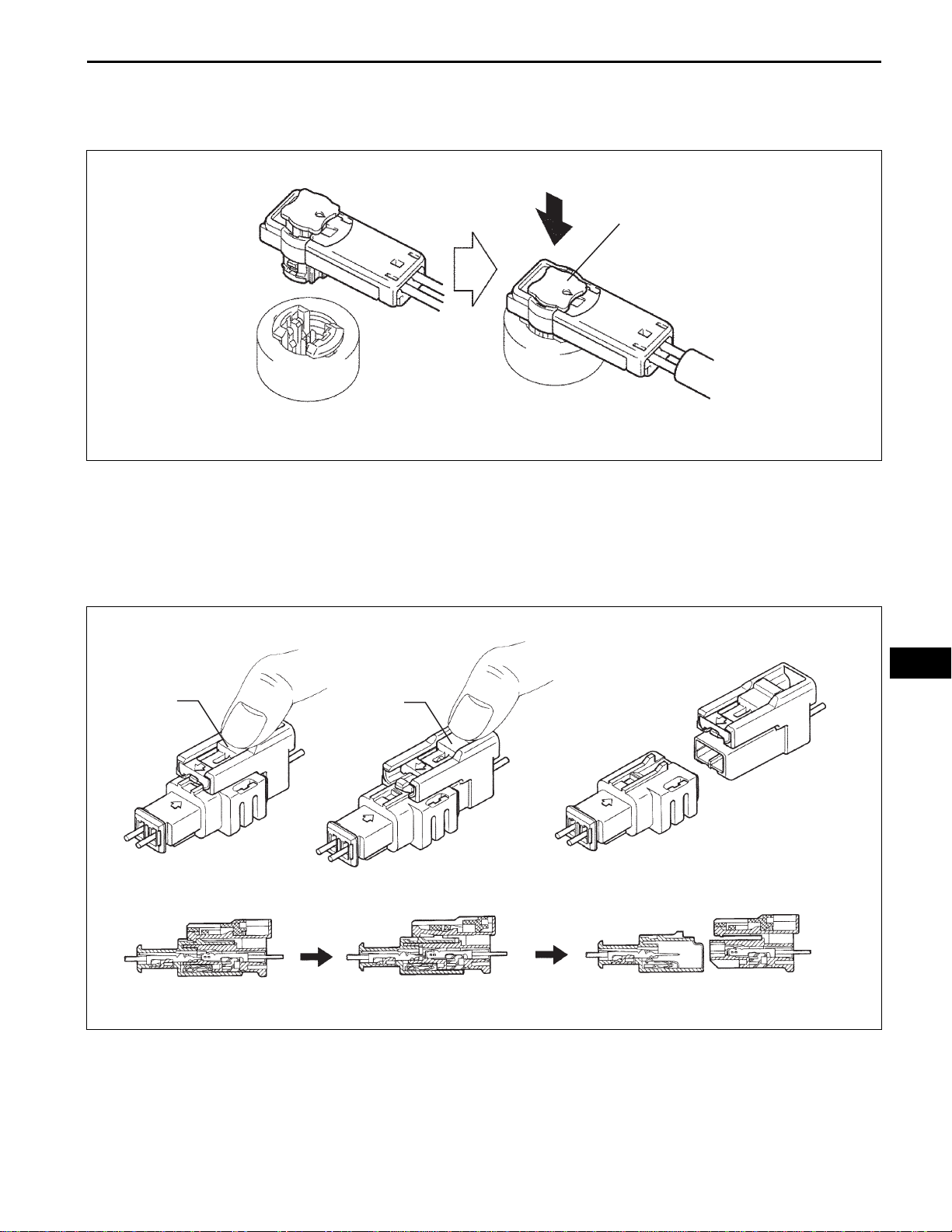
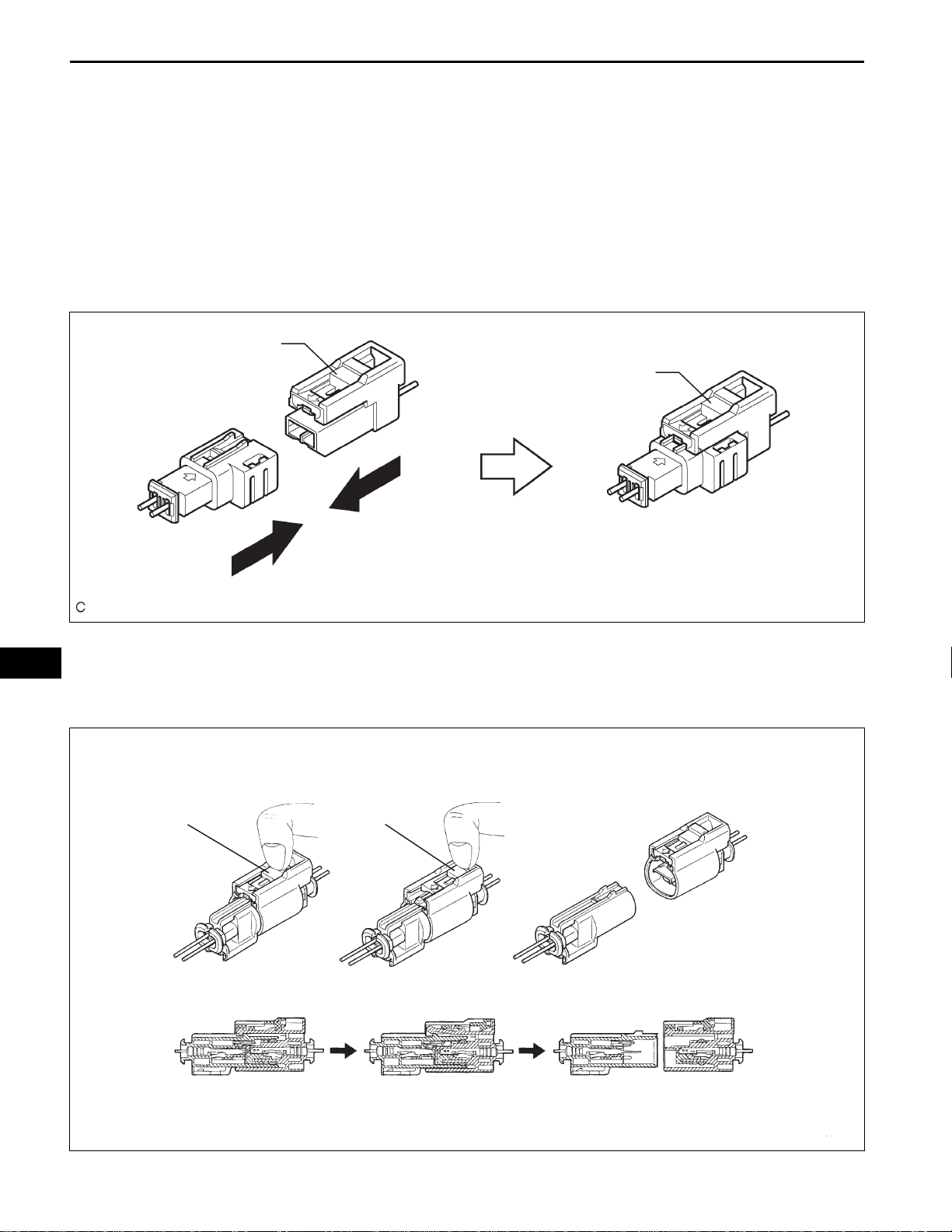
15. DISCONNECTION OF CONNECTORS FOR SIDE
AIRBAG SENSOR AND REAR AIRBAG SENSOR
(a) While holding the sides of the outer connector
locking sleeve, slide the outer in the direction shown
by the arrow.
(b) When the connector lock is released, the
connectors are disconnected.
HINT:
Be sure to hold both outer flank sides. Holding the
top and bottom will make disconnection difficult.
Disconnection is completed
H002764E02
RS
16. CONNECTION OF CONNECTORS FOR SIDE AIRBAG
SENSOR AND REAR AIRBAG SENSOR
(a) Connect the connector as shown in the illustration
(When locking, make sure that the outer returns to
its original position and a click sound can be heard).
HINT:
When connecting, the outer will slide. Be sure not to
hold the outer while connecting, as it may result in
an insecure fit.
Outer
Outer
Connection is completed
H002768E02
SUPPLEMENTAL RESTRAINT SYSTEM – AIRBAG SYSTEM
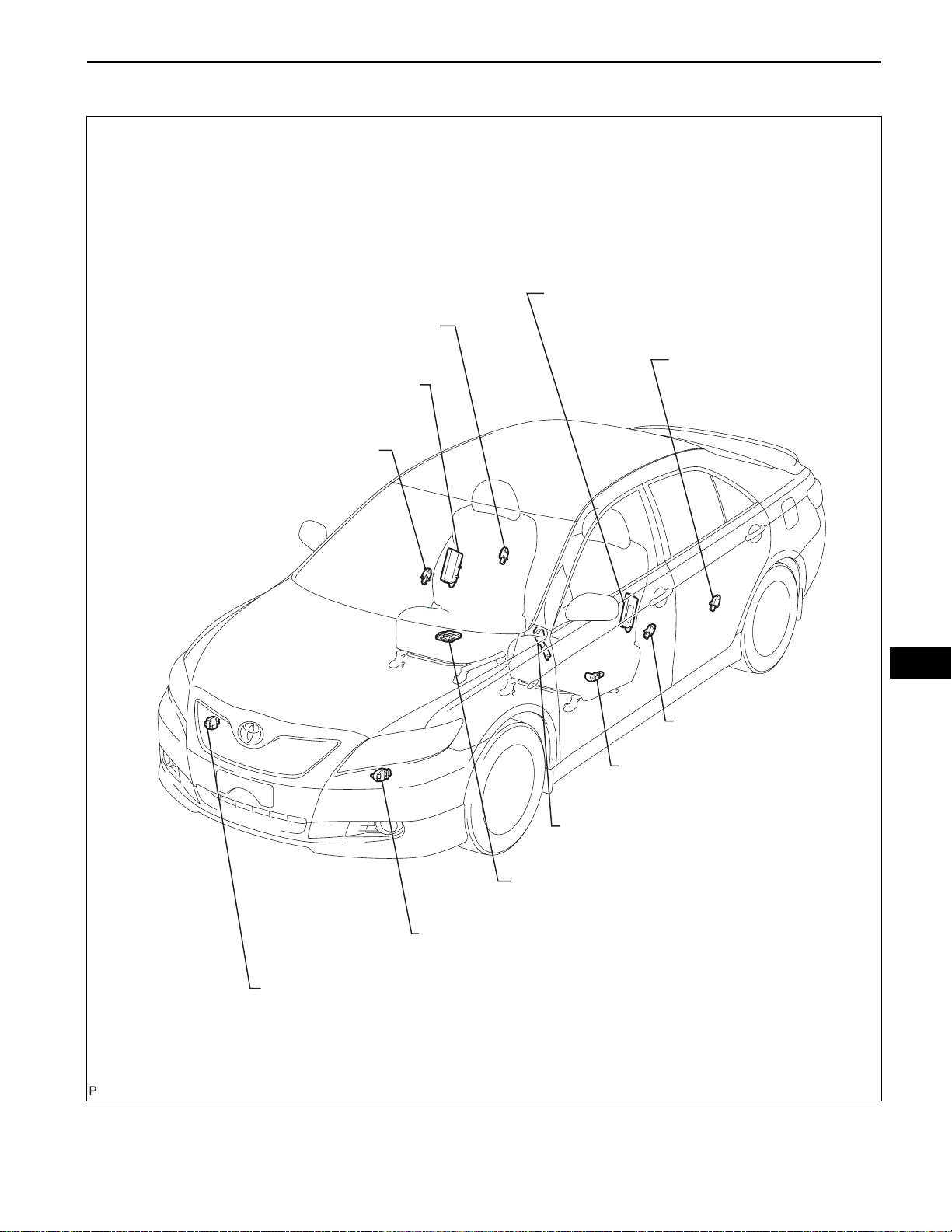
PARTS LOCATION
RS–19
REAR AIRBAG SENSOR
FRONT SEAT SIDE AIRBAG ASSEMBLY
SIDE AIRBAG SENSOR
RH
RH
RH
FRONT SEAT SIDE AIRBAG ASSEMBLY
REAR AIRBAG SENSOR
SIDE AIRBAG SENSOR
LH
LH
RS
LH
FRONT AIRBAG SENSOR
FRONT AIRBAG SENSOR
SEAT POSITION SENSOR
FRONT SEAT INNER BELT ASSEMBLY LH
OCCUPANT CLASSIFICATION ECU
LH
RH
C123718E02
RS–20
COMBINATION METER ASSEMBLY: CLOCK ASSEMBLY:
SUPPLEMENTAL RESTRAINT SYSTEM – AIRBAG SYSTEM
SRS WARNING LIGHT
CURTAIN SHIELD AIRBAG
ASSEMBLY
LH
PASSENGER AIRBAG ON/OFF INDICATOR
FRONT PASSENGER AIRBAG ASSEMBLY
CURTAIN SHIELD AIRBAG ASSEMBLY
FRONT SEAT OUTER
BELT ASSEMBLY RH
RH
RS
DRIVER SIDE KNEE
AIRBAG ASSEMBLY
SPIRAL CABLE
STEERING PAD
CENTER AIRBAG SENSOR ASSEMBLY
FRONT SEAT OUTER BELT ASSEMBLY LH
C123719E01
SUPPLEMENTAL RESTRAINT SYSTEM – AIRBAG SYSTEM
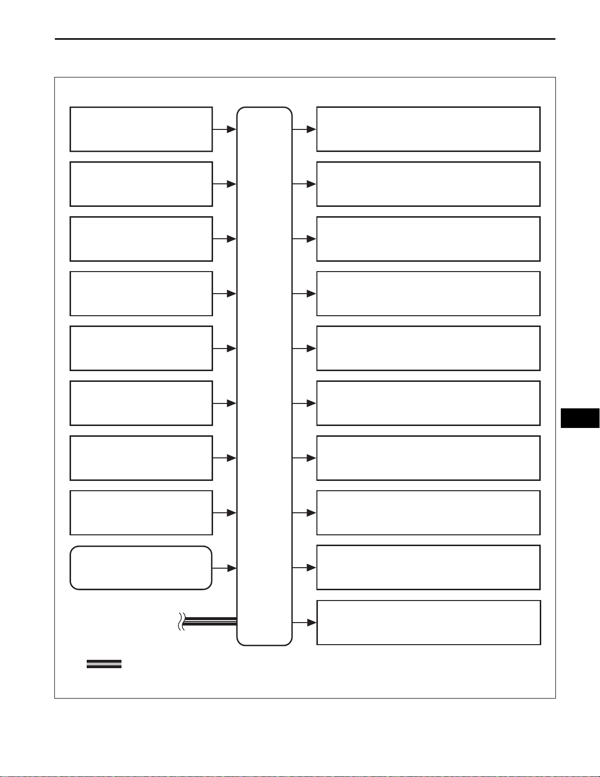
SYSTEM DIAGRAM
RS–21
Front Airbag Sensor LH
Front Airbag Sensor RH
Side Airbag Sensor LH
Side Airbag Sensor RH
Rear Airbag Sensor LH
Rear Airbag Sensor RH
Steering Pad (Driver Side Squib)
Front Passenger Airbag Assembly (Front Passenger
Side Squib)
Driver Side Knee Airbag Assembly (Driver Side Knee
Airbag Squib)
Front Seat Side Airbag Assembly LH (Driver Side - Side Squib)
Front Seat Side Airbag Assembly RH (Front Passenger Side
- Side Squib)
Curtain Shield Airbag Assembly LH (Driver Side Curtain
Shield Squib)
Seat Position Airbag Sensor
Front Seat Inner Belt Assembly LH
(Driver Side Seat Belt Buckle Switch LH)
Occupant Classification ECU
: CAN
RS
Curtain Shield Airbag Assembly RH (Front Passenger Side
Curtain Shield Squib)
Front Seat Outer Belt Assembly LH (Driver Side Front
Pretensioner Squib)
Front Seat Outer Belt Assembly RH (Front Passenger Side
Front Pretensioner Squib)
Clock Assembly (Passenger Airbag ON/OFF Indicator)
C123736E01
RS–22
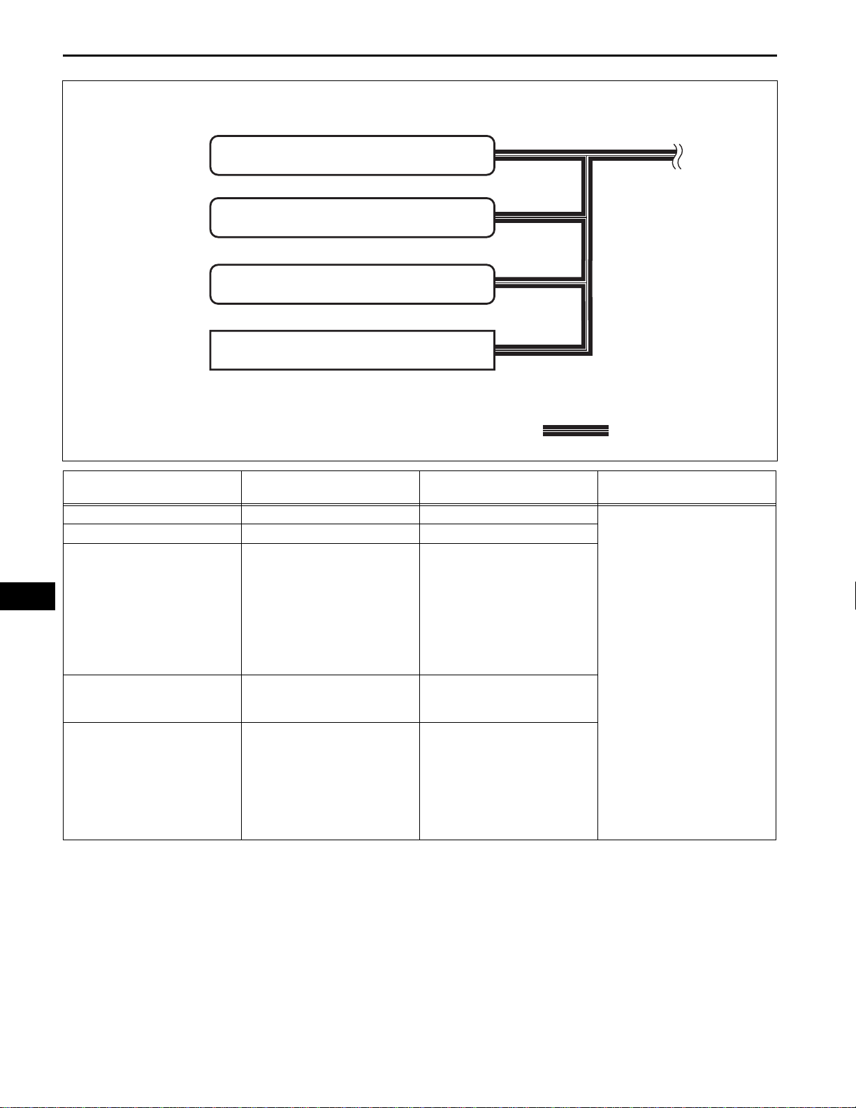
SUPPLEMENTAL RESTRAINT SYSTEM – AIRBAG SYSTEM
ECM
Main Body ECU
Combination Meter Assembly
DLC3
: CAN
C123737E01
RS
Transmitting ECU
(Transmitter)
Center Airbag Sensor Assembly ECM Crash detection signal
Center Airbag Sensor Assembly Main Body ECU Driver seat buckle switch signal
Center Airbag Sensor Assembly Combination Meter Assembly
Combination Meter Assembly Center Airbag Sensor Assembly
ECM Center Airbag Sensor Assembly
Receiving ECU Signals Communication method
• SRS warning light ON
demand signal
• SRS warning light blink
demand signal
• Passenger seat occupant
detection signal
• Passenger seat buckle switch
signal
• Diagnosis signal (DTC)
• Vehicle speed signal
• Meter diagnoses polling
signal
• Engine speed signal
• Accelerator opening angle
information
• Accelerator opening angle
signal
• Shift position signal
• Test mode signal
• Stop signal
CAN

SUPPLEMENTAL RESTRAINT SYSTEM – AIRBAG SYSTEM
SYSTEM DESCRIPTION
1. GENERAL
(a) In conjunction with impact absorbing structure for a
front collision, the SRS (Supplemental Restraint
System) driver airbag, front passenger airbag, and
driver side knee airbag were designed to
supplement seat belts in the event of a front
collision in order to help reduce shock to the head
and chest of the driver and front passenger and
knee of the driver. This system is a 3-sensor type
airbag system to detect the impact during a front
collision using the center airbag sensor assembly
and front airbag sensors. It also operates the airbag
system and seat belt pretensioner.
(b) In order to detect the extent of the collision during
the initial stages of the collision in further details, the
front airbag sensors have been changed from
mechanical type to electrical type deceleration
sensors. Accordingly, the deployment of the driver
airbag and front passenger airbag is controlled in
two stages according to the severity of the impact.
(c) In conjunction with impact absorbing structure for a
side collision, the side airbag and curtain shield
airbag were designed to help reduce shock to the
driver, front passenger, and rear outer passengers
in the event of a side collision.
(d) The curtain shield airbag that helps reduce shock to
the front and rear seat occupants with a single
curtain shield airbag has been adopted. In
conjunction with this system, the side airbag
sensors have been installed at the bottom of the
center pillars and the rear airbag sensors have been
installed at the bottom of the rear pillars.
(e) In this system, a front side collision is detected by
the side airbag sensor in order to simultaneously
deploy the side and curtain shield airbags. A rear
side collision is detected by the rear airbag sensor
and the center airbag sensor assembly in order to
deploy the curtain shield airbag.
(f) The center airbag sensor assembly sends the
airbag deployment signal to the ECM through CAN
(Controller Area Network) to operate the fuel pump
control.
2. CONSTRUCTION AND OPERATION
(a) FRONT AIRBAG SENSOR
(1) The front airbag sensors are installed on the
right and left radiator supports respectively.
(2) The front airbag sensor consists of the
deceleration sensor.
RS–23
RS

RS
RS–24
SUPPLEMENTAL RESTRAINT SYSTEM – AIRBAG SYSTEM
(3) The deceleration sensor is built into the front
airbag sensor, and the distortion that is created
in the sensor is converted into an electric signal
based on the vehicle deceleration rate during a
frontal collision. Accordingly, the extent of the
initial collision can be detected in detail.
(b) SIDE AIRBAG SENSOR
(1) The side airbag sensors are installed on the
bottom of the right and left center pillars
respectively.
(2) The side airbag sensor consists of the
deceleration sensor and ignition control circuit.
(3) The deceleration sensor is built into the side
airbag sensor, and the distortion that is created
in the sensor is converted into an electric signal
based on the vehicle deceleration rate during a
front side collision. Accordingly, the extent of the
initial collision can be detected in detail.
(c) REAR AIRBAG SENSOR
(1) The rear airbag sensors are installed on the right
and left rear pillars respectively.
(2) The rear airbag sensor consists of the
deceleration sensor and ignition control circuit.
(3) The deceleration sensor is built into the rear
airbag sensor, and the distortion that is created
in the sensor is converted into an electric signal
based on the vehicle deceleration rate during a
rear side collision. Accordingly, the extent of the
initial collision can be detected in detail.
(d) CENTER AIRBAG SENSOR ASSEMBLY
(1) General
• The center airbag sensor assembly is
installed on the center floor under the
instrument panel.
• The center airbag sensor assembly consists
of the deceleration sensor, safing sensor,
electronic safing sensor, ignition control
circuit, and diagnostic circuit.
• The center airbag sensor assembly receives
signals from the deceleration sensor and
safing sensor built into the center airbag
sensor assembly and front airbag sensor.
Then the center airbag sensor assembly
determines whether the driver airbag, front
passenger airbag, driver side knee airbag,
and front seat belt pretensioners should be
activated, and diagnoses system
malfunctions.
• The center airbag sensor assembly causes
the front seat side airbag assembly and the
curtain shield airbag assembly to deploy
when receiving signals from the side airbag
sensor.

SUPPLEMENTAL RESTRAINT SYSTEM – AIRBAG SYSTEM
• The center airbag sensor assembly receives
signals from the deceleration sensor and the
electronic safing sensor built into the center
airbag sensor assembly and the rear airbag
sensor, and determines whether the curtain
shield airbag should be activated, and
diagnoses system malfunctions.
• The center airbag sensor assembly sends the
airbag deployment signal to the ECM through
CAN to operate the fuel pump control.
(2) Deceleration sensor and ignition control circuit
• The deceleration sensor is built into the
center airbag sensor assembly.
• The ignition control circuit performs
calculations based on the signal output from
the deceleration sensors of the center airbag
sensor assembly and front airbag sensor. If
the calculated values are greater than the
specified values, it activates ignition
operation.
(3) Safing sensor
• The safing sensor is built into the center
airbag sensor assembly. During a front
collision, the sensor turns on and outputs an
ON signal to the center airbag sensor
assembly if a deceleration rate sent to the
safing sensor is greater than the specified
value.
(4) Electronic safing sensor
• The electronic safing sensor is built into the
center airbag sensor assembly. During a side
collision, the sensor turns on and outputs an
ON signal to the center airbag sensor
assembly if a deceleration rate sent to the
electronic safing sensor is greater than the
specified value.
(5) Backup power source
• The backup power source consists of a
power supply capacitor and a DC-DC
converter. When the power system does not
function during a collision, the power supply
capacitor discharges and supplies electric
power to the system. The DC-DC converter
operates as a boosting transformer when the
battery voltage falls below a predetermined
level.
(6) Diagnostic circuit
• This circuit constantly diagnoses system
malfunctions. When a malfunction is
detected, it turns on the SRS warning light on
the combination meter assembly to inform the
driver.
RS–25
RS

RS–26
SUPPLEMENTAL RESTRAINT SYSTEM – AIRBAG SYSTEM
(7) Memory circuit
• When a malfunction is detected in the
diagnostic circuit, it is coded and stored in the
memory circuit.
(e) SRS WARNING LIGHT
(1) The SRS warning light is located on the
combination meter assembly. It comes on to
inform the driver of system trouble when a
malfunction is detected in self-diagnosis of the
center airbag sensor assembly. Under normal
operating conditions when the ignition switch is
turned on (IG), it comes on for approximately 6
seconds and then goes off.
RS
SUPPLEMENTAL RESTRAINT SYSTEM – AIRBAG SYSTEM
Center Airbag Sensor Assembly
RS–27
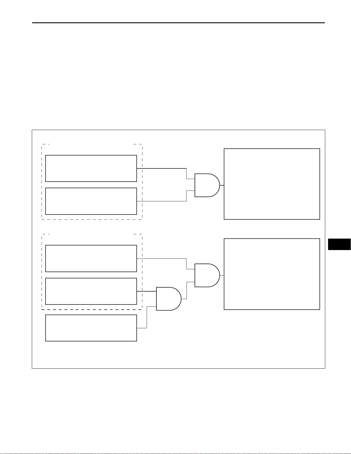
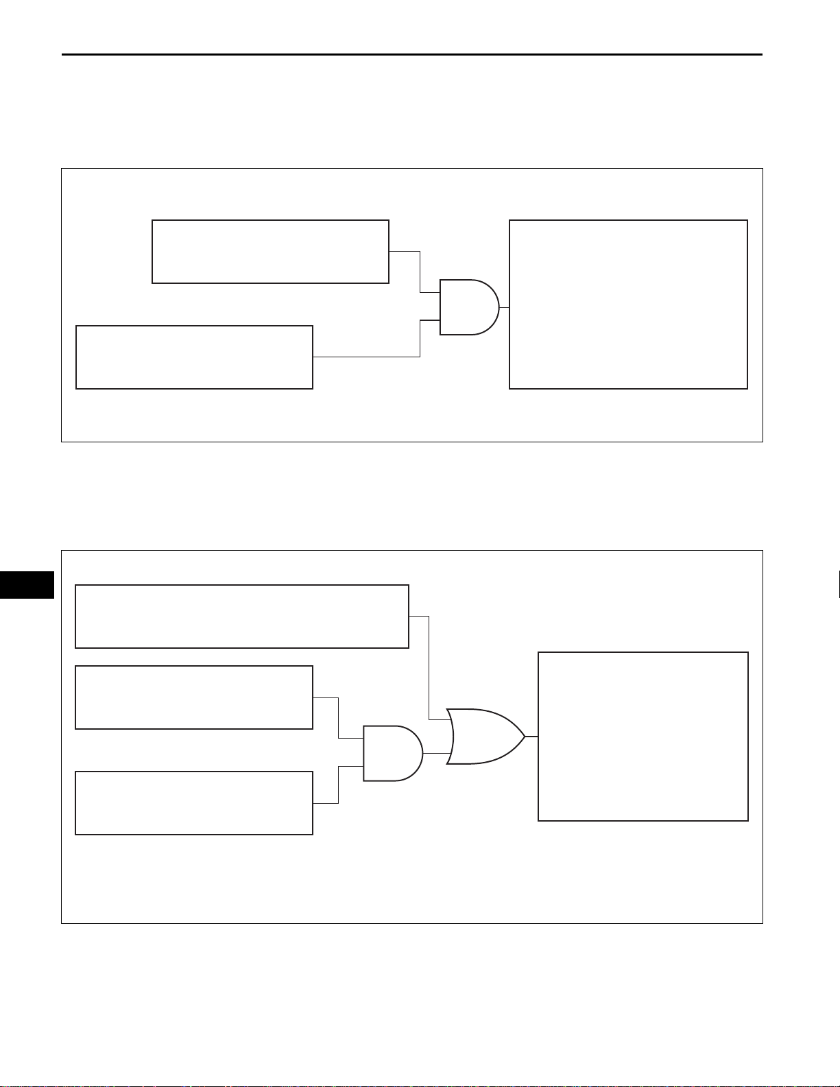
3. DEPLOYMENT CONDITION
When the vehicle collides and the shock is greater than
the specified value, the SRS is activated automatically.
The center airbag sensor assembly includes the safing
sensor and deceleration sensor. The safing sensor is
designed to turn on at a smaller deceleration rate than
the deceleration sensor.
(a) The center airbag sensor assembly determines
whether ignition is necessary based on signals from
the deceleration sensor and the front airbag sensor
(*1). If the safing sensor turns on simultaneously,
current flows to the squibs to deploy the SRS as
shown in the illustration below.
Steering Pad
Safing Sensor ON
Deceleration Sensor ON
Center Airbag Sensor Assembly
Safing Sensor ON
Deceleration Sensor ON
Front Airbag Sensor (*1)
AND
AND
AND
Front Passenger Airbag Assembly
Driver Side Knee Airbag Assembly
Front Seat Outer Belt Assembly
Steering Pad
Front Passenger Airbag Assembly
Driver Side Knee Airbag Assembly
Front Seat Outer Belt Assembly
RS
C
C109526E05
HINT:
*1: In case of front collision, the ignition signal could
be output with the deceleration sensor ON signal
even without a signal from the front airbag sensor.
RS–28
SUPPLEMENTAL RESTRAINT SYSTEM – AIRBAG SYSTEM
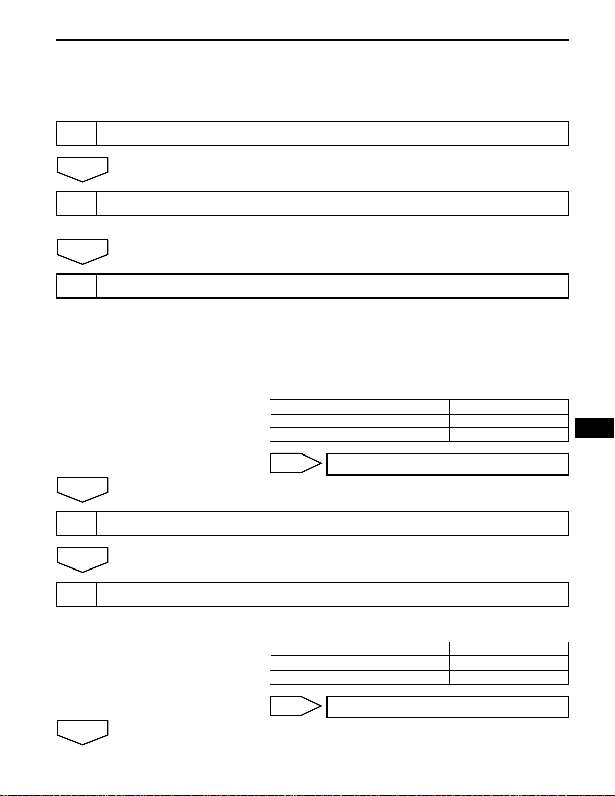
(b) The center airbag sensor assembly determines
whether ignition is necessary based on signals from
the side airbag sensor. If the safing sensor turns on
simultaneously, current flows to the squib to deploy
the SRS as shown in the illustration below.
Center Airbag Sensor Assembly
Safing Sensor
Front Seat Side Airbag Assembly
AND
Curtain Shield Airbag Assembly
Side Airbag Sensor
RS
C
Front Seat Side Airbag Assembly Deployment
Safing Sensor
Center Airbag Sensor Assembly
Rear Airbag Sensor (*1)
(c) The center airbag sensor assembly determines
whether ignition is necessary based on signals from
the rear airbag sensor. If the safing sensor turns on
simultaneously, current flows to the squib to deploy
the SRS as shown in the illustration below (*1).
OR
AND
Curtain Shield Airbag Assembly
C109527E12
C
C109528E03
HINT:
*1: If the front seat side airbag assembly deploys,
the curtain shield airbag assembly will also deploy,
regardless of whether the signal is output from the
rear airbag sensor.
1
NEXT
2
NEXT
3
SUPPLEMENTAL RESTRAINT SYSTEM – AIRBAG SYSTEM
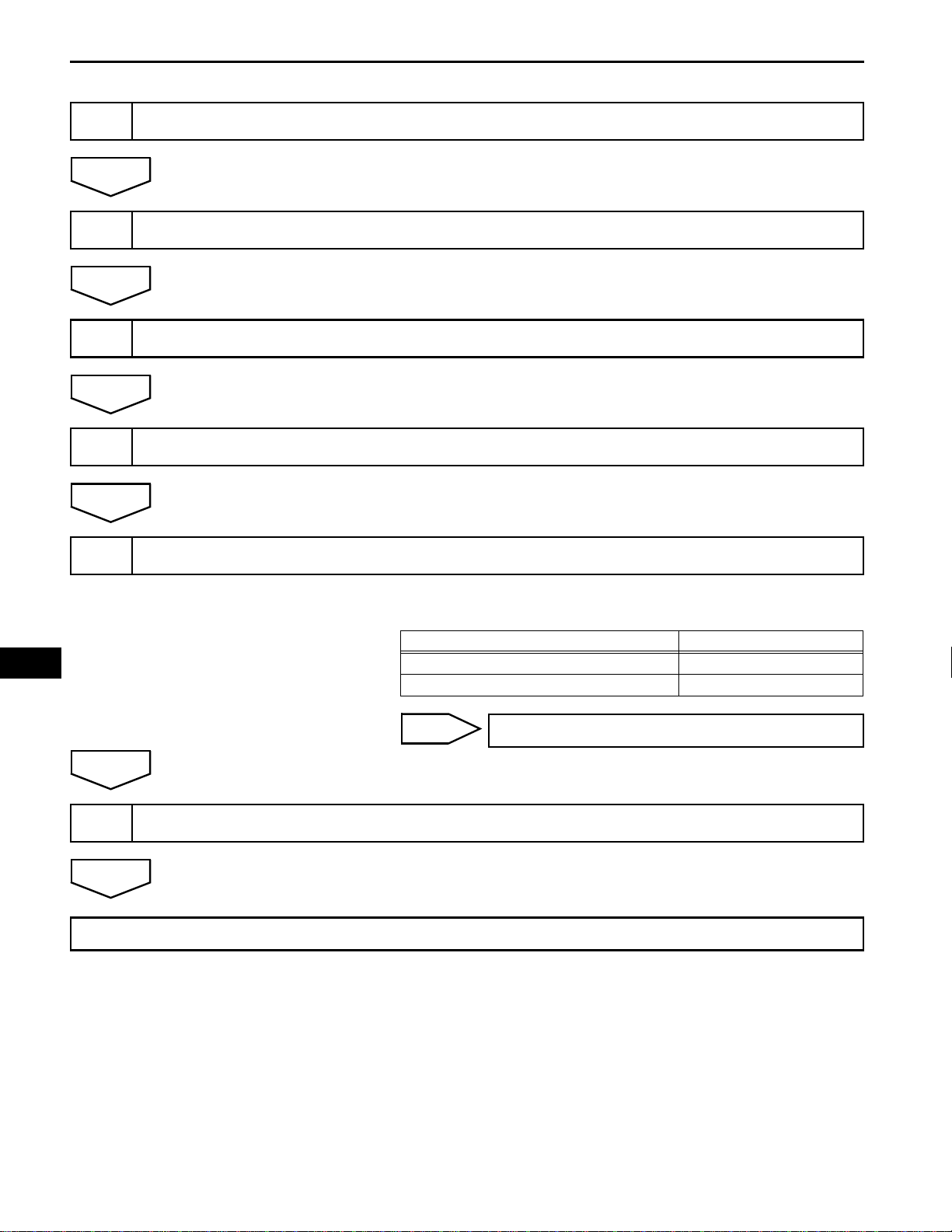
HOW TO PROCEED WITH
TROUBLESHOOTING
The intelligent tester can be used in steps 3, 5, 7, 9, and 10.
VEHICLE BROUGHT TO WORKSHOP
CUSTOMER PROBLEM ANALYSIS
(a) Confirm problem symptoms (See page IN-45).
CHECK CAN COMMUNICATION SYSTEM
(a) Check for DTC outputs.
HINT:
The center airbag sensor assembly is connected to the
CAN communication system. Therefore, before starting
troubleshooting, make sure to check that there is no
trouble in the CAN communication system.
Result
CAN communication DTC is not output. A
CAN communication DTC is output. B
RS–29
Result Proceed To
RS
A
4
NEXT
5
A
B
WARNING LIGHT CHECK
CHECK DTC (Present and Past DTCs)
(a) Check for DTC outputs.
Result
DTC is output. A
DTC is not output. B
B
INSPECT CAN COMMUNICATION CIRCUIT
Result Proceed To
PROBLEM SYMPTOMS TABLE
RS–30
6
NEXT
7
NEXT
8
NEXT
9
SUPPLEMENTAL RESTRAINT SYSTEM – AIRBAG SYSTEM
DTC CHART
CIRCUIT INSPECTION
REPAIR
CLEAR DTC (Present and Past DTCs)
RS
NEXT
10
11
NEXT
END
CHECK DTC (Present and Past DTCs)
A
CONFIRMATION TEST
(a) Check for DTC outputs.
Result
Result Proceed To
DTC is not output. A
DTC is output. B
B
Go to step 6
 Loading...