


A-PDF Merger DEMO : Purchase from www.A-PDF.com to remove the watermark
POWER STEERING – POWER STEERING SYSTEM
POWER STEERING SYSTEM
PRECAUTION
NOTICE:
When disconnecting the cable from the negative (-)
battery terminal, initialize the systems after the cable is
reconnected (See page IN-43).
1. HANDLING PRECAUTIONS FOR STEERING SYSTEM
(a) Care must be taken when replacing parts. Incorrect
replacement may affect the performance of the
steering system and result in driving hazards.
2. HANDLING PRECAUTIONS FOR SRS AIRBAG
SYSTEM
(a) The vehicle is equipped with SRS (Supplemental
Restraint System), such as airbags. If service
operation is not carried out properly, in a step by
step fashion, sudden deployment of the airbags
may result in serious injury. Before servicing
(including removal or installation of parts, inspe ction
or replacement), be sure to read the precautionary
notice for the supplemental restraint system (See
page RS-1).
3. PRECAUTIONS FOR REMOV AL, INST ALLA TION AND
REPLACEMENT OF ELECTRONIC MOTOR POWER
STEERING COMPONENTS
(a) Be sure to turn the front wheels straight ahead when
removing and installing the power steering link
assembly.
(b) If disconnecting the steering intermediate shaft sub-
assembly and the power steering link assembly, be
sure to put matchmarks before starting the
operation.
(c) After replacing the power steering link assembly or
power steering ECU assembly, clear the rotation
angle sensor calibration value, initialize the rotation
angle sensor, and calibrate torque sensor zero point
(See page PS-13).
PS–1
PS

PS
PS–2
POWER STEERING – POWER STEERING SYSTEM
POWER STEERING SYSTEM
Symptom Suspected Area See page
Steering is heavy.
Steering effort differs between right and left or is
uneven.
While driving, steering effort does not change in
accordance with vehicle speed or the steering wheel
does not return properly.
A knocking (or cranking) sound occurs when turning
the steering wheel back and forth while power steering
is in operation.
Noise occurs when turning the steering wheel during
low speed driving.
A high-pitched sound (squeaking) occurs when turning
the steering wheel slowly with the vehicle stopped.
The steering wheel vibrates and noise occurs when
turning the steering wheel from lock to lock.
PROBLEM SYMPTOMS TABLE
HINT:
Use the table below to help determine the cause of the
problem. The numbers indicate likely causes of the problem
in descending order. Check each part in order. If necessary,
repair or replace faulty parts.
1. Front tires (Improperly inflated, unevenly worn) TW-3
2. Front wheel alignment (Incorrect) SP-4
3. Front suspension (Lower ball joint) SP-24
4. Steering column assembly SR-35
5. Torque sensor (Built into steering link assembly) -
6. Power steering motor -
7. Speed sensor -
8. Skid control ECU -
9. Battery and power source system -
10. Power steering ECU power source voltage and relay -
11. Power steering ECU PS-68
1. Calibration of turning angle sensor output and torque sensor
zero point is not completed
2. Front tires (Improperly inflated, unevenly worn) TW-3
3. Front wheel alignment (Incorrect) SP-4
4. Front suspension (Lower ball joint) SP-24
5. Power steering link assembly PS-58
6. Torque sensor (Built into steering link assembly) -
7. Steering column assembly SR-35
8. Power steering motor -
9. Power steering ECU PS-68
1. Front suspension (Lower ball joint) SP-24
2. Speed sensor -
3. Skid control ECU -
4. Combination meter -
5. Engine speed detection circuit -
6. Torque sensor (Built into steering link assembly) -
7. Power steering motor -
8. Power steering ECU PS-68
1. Front suspension (Lower ball joint) SP-24
2. Steering intermediate shaft -
3. Power steering link assembly PS-58
1. Power steering link assembly PS-58
2. Steering column assembly SR-35
1. Power steering motor
1. Power steering link assembly PS-58
2. Steering column assembly SR-35
PS-13
-
POWER STEERING – POWER STEERING SYSTEM
ON-VEHICLE INSPECTION
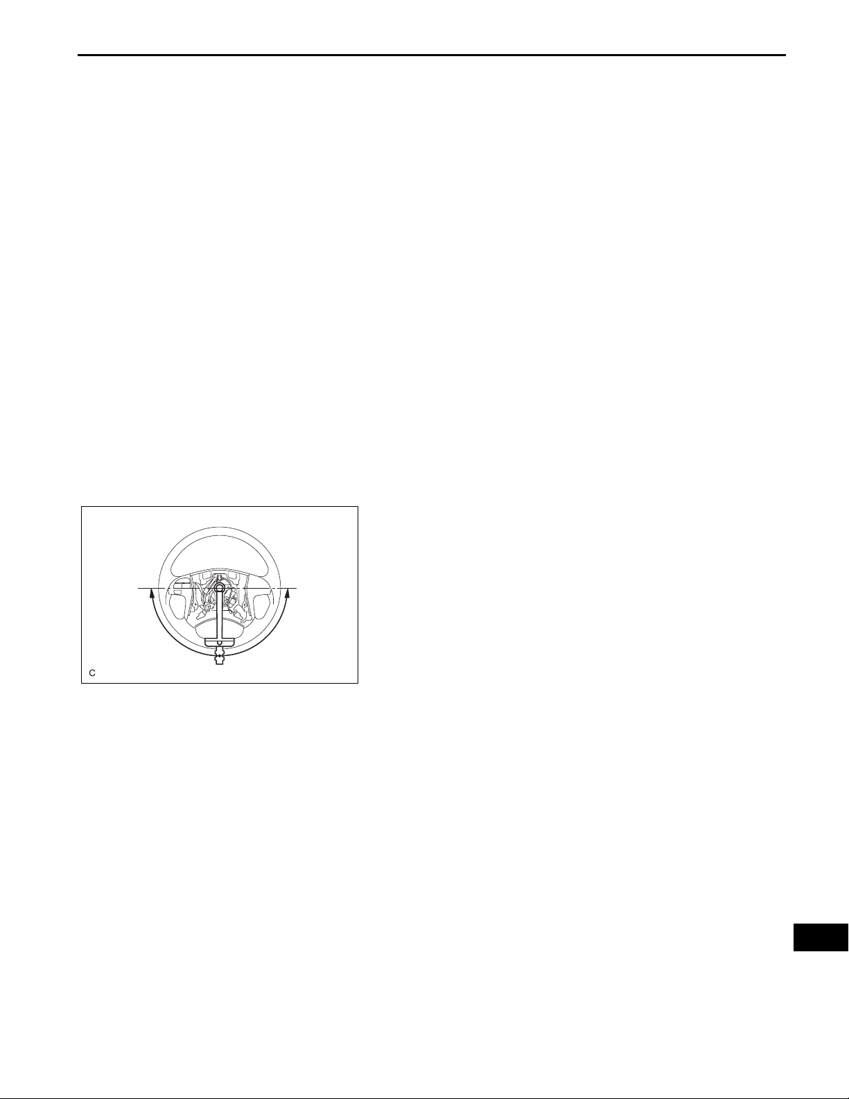
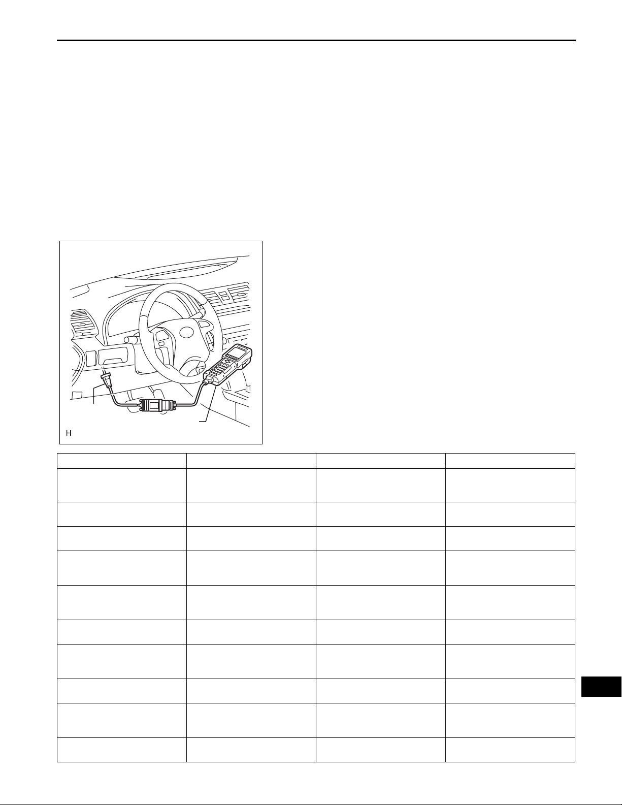
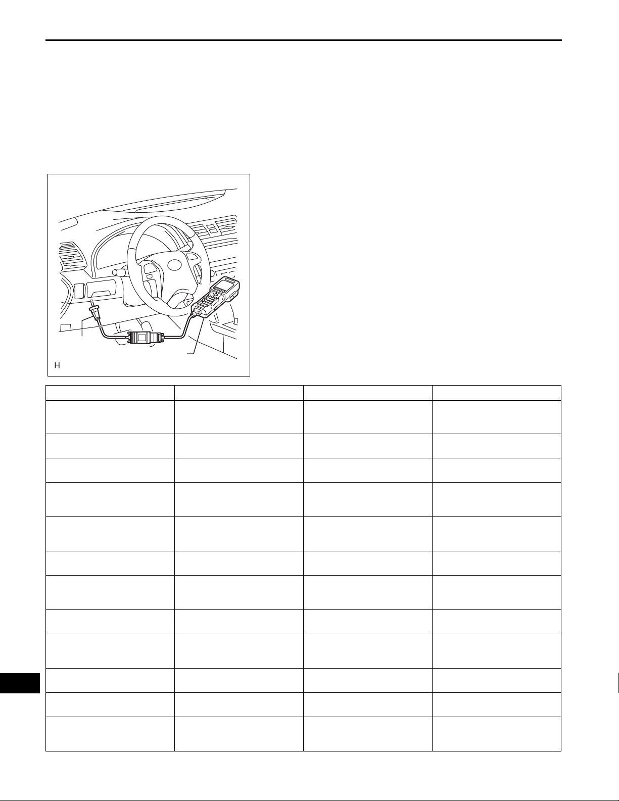
1. CHECK STEERING EFFORT (TORQUE)
NOTICE:
Some service operations affect the SRS airbags. Be
sure to read the precautionary notice for the SRS
airbags before servicing (See page RS-1).
(a) Stop the vehicle on a level, paved surface and align
the wheels straight ahead.
(b) Disconnect the cable from the negative (-) battery
terminal.
CAUTION:
Wait at least 90 seconds after disconnecting the
cable from the negative (-) battery terminal to
prevent airbag and seat belt pretensioner
activation.
(c) Remove the steering pad (See page RS-344).
(d) Connect the cable to the negative (-) battery
terminal.
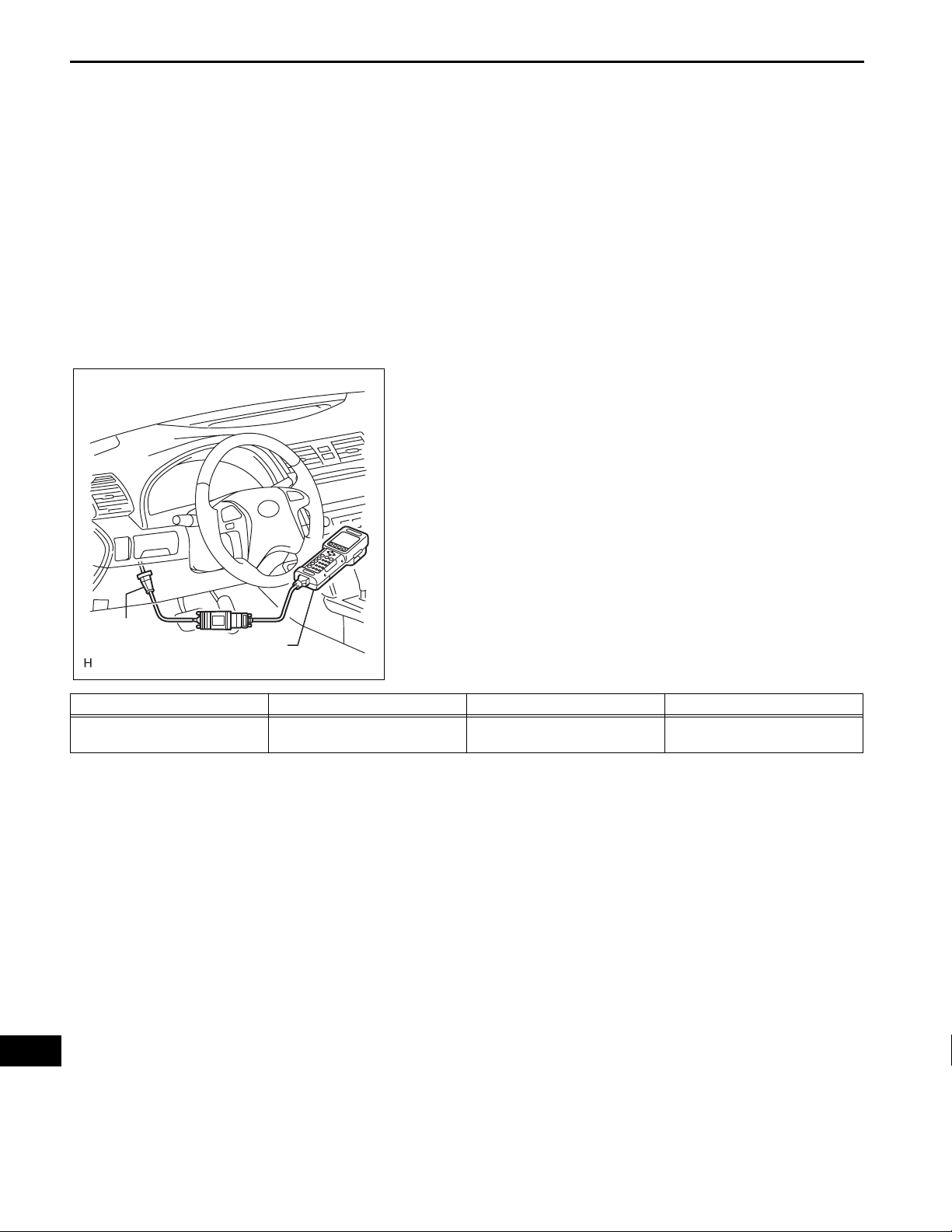
(e) Using a torque wrench, check if the steering wheel
set nut is properly tightened.
Torque: 50 N*m (510 kgf*cm, 37 ft.*lbf)
(f) Turn the power switch on (READY) so that the
power steering is available.
PS–3
C132536
(g) Turn the steering wheel 90 degrees to the right and
check steering effort (torque) while turning. Check in
the opposite direction using the same manner.
Steering effort (Reference):
6.0 N*m (60 kgf*cm, 53 in.*lbf) or less
Inspect the power steering system if the value is not
within the specified range (See page PS-1).
(h) Align the front wheels straight ahead.
(i) Disconnect the cable from the negative (-) battery
terminal.
(j) Install the steering pad (See page RS-346).
(k) Connect the cable to the negative (-) battery
terminal.
(l) Clear the DTCs (See page RS-41).
(m) Perform initialization.
NOTICE:
Some systems need initialization after
reconnecting the cable to the negative battery
terminal (See page IN-43).
(n) Inspect the airbag warning light (See Page RS-33).
PS

PS
PS–4
POWER STEERING – ELECTRONIC POWER STEERING SYSTEM
ELECTRONIC POWER STEERING
SYSTEM
PRECAUTION
1. NOTICE FOR INITIALIZATION
(a) When disconnecting the negative (-) battery
terminal, initialize the following systems after the
terminal is reconnected.
System Name See procedure
SFI System (See page IN-43)
2. HANDLING PRECAUTIONS
(a) When handling the electronic parts:
(1) Avoid any impact to electronic parts such as
ECUs and relays. Replace these parts with new
ones if dropped or subjected to a severe blow.
(2) Do not expose any electronic parts to high
temperature or humidity.
(3) Do not touch the connector terminals in order to
prevent deformation or malfunctions due to
static electricity.
(4) If the power steering ECU assembly has been
replaced with a new one, initialize the rotation
angle sensor value and calibrate the torque
sensor zero point (See page PS-13).
(b) When handling the power steering link assembly:
(1) Avoid any impact to the power steering link
assembly, especially to the motor or torque
sensor. Replace these parts with new ones if
dropped or subjected to a severe blow.
(2) Do not pull on the wire harness when moving the
power steering link assembly.
(3) If the power steering link assembly has been
replaced with a new one, clear the rotation angle
sensor calibration value, initialize the rotation
angle sensor value, and calibrate the torque
sensor zero point (See page PS-13).
(c) When disconnecting and reconnecting the
connectors:
(1) Turn the power switch on (IG), center the
steering wheel, and turn the power switch off
again before disconnecting the connectors
related to the electronic power steering system.
(2) Ensure that the power switch is off before
reconnecting the connectors related to the
electronic power steering system. After
reconnection, center the steering wheel and turn
the power switch on (IG).
NOTICE:
Do not turn the power switch on (IG) when
the steering wheel is not centered.
POWER STEERING – ELECTRONIC POWER STEERING SYSTEM
(3) If the above operations are not carried out
properly, the steering center point (zero point)
will deviate, which may lead to a difference in
steering effort between right and lef t. If there is a
difference in steering effort between right and
left, perform steering zero point calibration (See
page PS-13).
3. PRECAUTIONS FOR CAN COMMUNICATION
(a) CAN communication is used to receive information
from the skid control ECU, power steering ECU,
hybrid vehicle control ECU, and steering angle
sensor and to transmit warnings to the combination
meter. It is also used for communication between
terminals Tc and Ts of the DLC3. If there are any
problems in the CAN communication lines, DTCs
indicating communication line malfunctions are
output.
(b) Perform troubleshooting for communication line
problems if CAN communication DTCs are output.
Be sure to start troubleshooting on the electronic
power steering system only when data
communication is normal.
(c) Temporary fixing or rep air with byp ass wiring, etc. is
impossible because the length and path of each
CAN communication line is specified.
PS–5
Bypass Wire
F045104E02
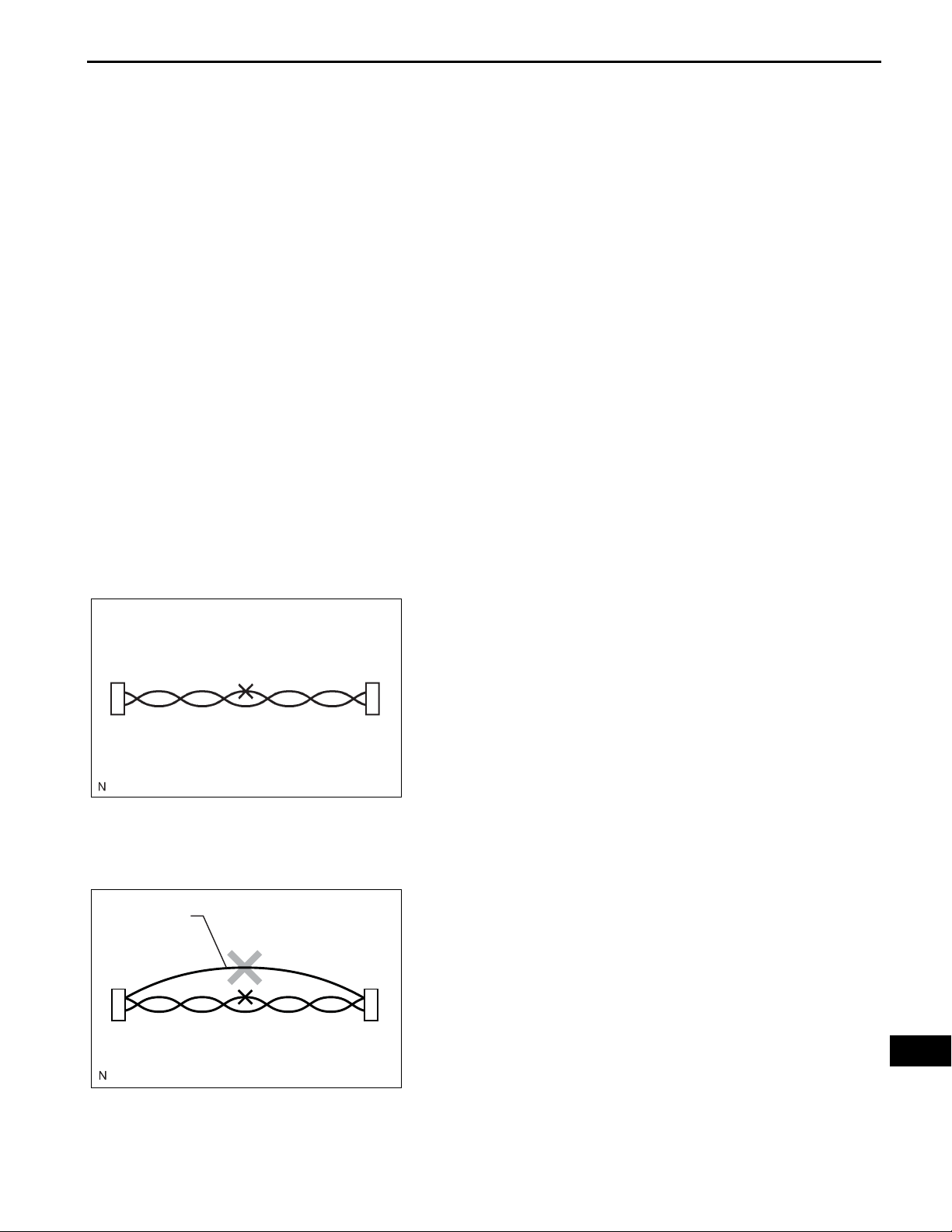
4. BUS LINE REPAIR
(a) After repairing the bus line with solder, wrap the
repaired part with electrical tape.
NOTICE:
• The CANL bus line and CANH bus line must
be installed together all the times.
When installing, make sure to twist them.
CAN bus lines are likely to be influenced by
electrical noise if they are not twisted.
• The difference in length between the CANL
bus line and CANH bus line should be 100
mm (3.937 in.) or less.
• Leave approximately 80 mm (3.150 in.) loose
in the twisted wires around the connector.
(b) Do not use bypass wiring between the connectors.
NOTICE:
The ability of the twisted bus lines to resist
interference will be lost if bypass wiring is used.
C106492E01
PS
PS–6
POWER STEERING – ELECTRONIC POWER STEERING SYSTEM
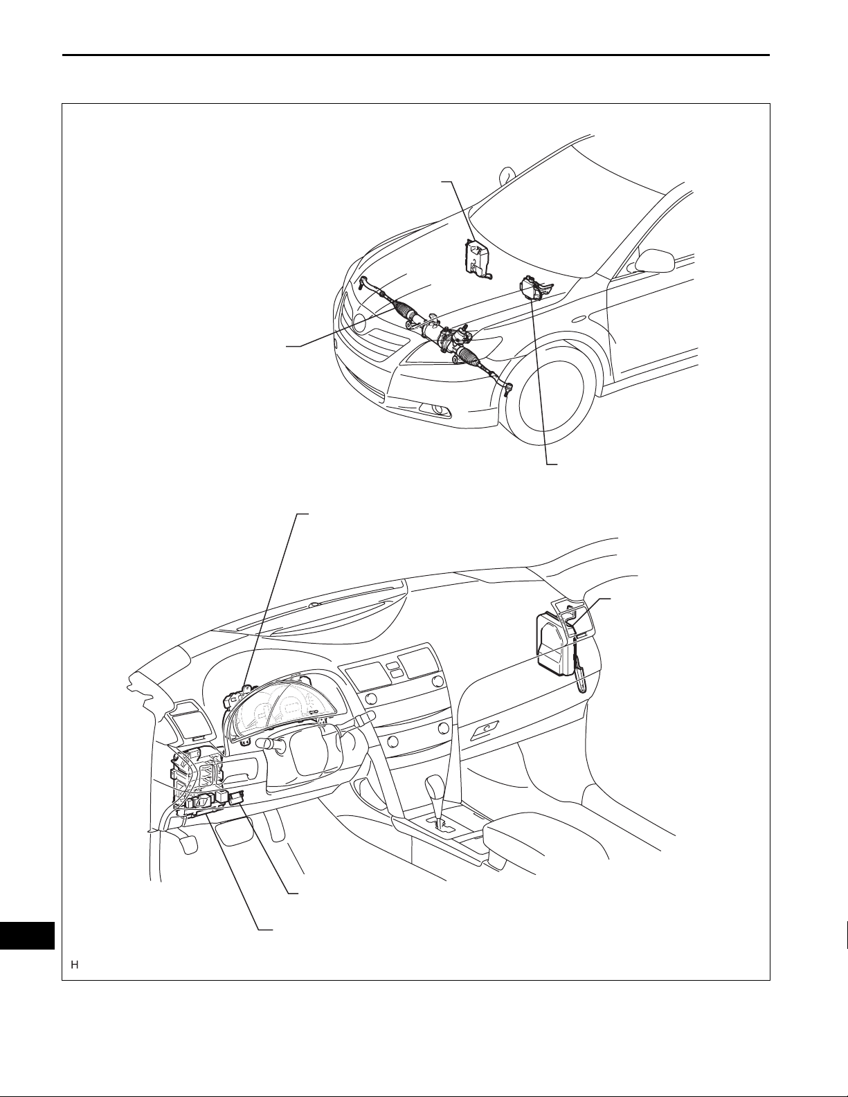
PARTS LOCATION
HYBRID VEHICLE CONTROL ECU
POWER STEERING LINK
- TORQUE SENSOR
- POWER STEERING MOTOR
- ROTATION ANGLE SENSOR
COMBINATION METER
- PS WARNING LIGHT
POWER STEERING ECU
SKID CONTROL ECU
PS
DLC3
MAIN BODY ECU (INSTRUMENT PANEL J/B)
B150822E01
POWER STEERING – ELECTRONIC POWER STEERING SYSTEM
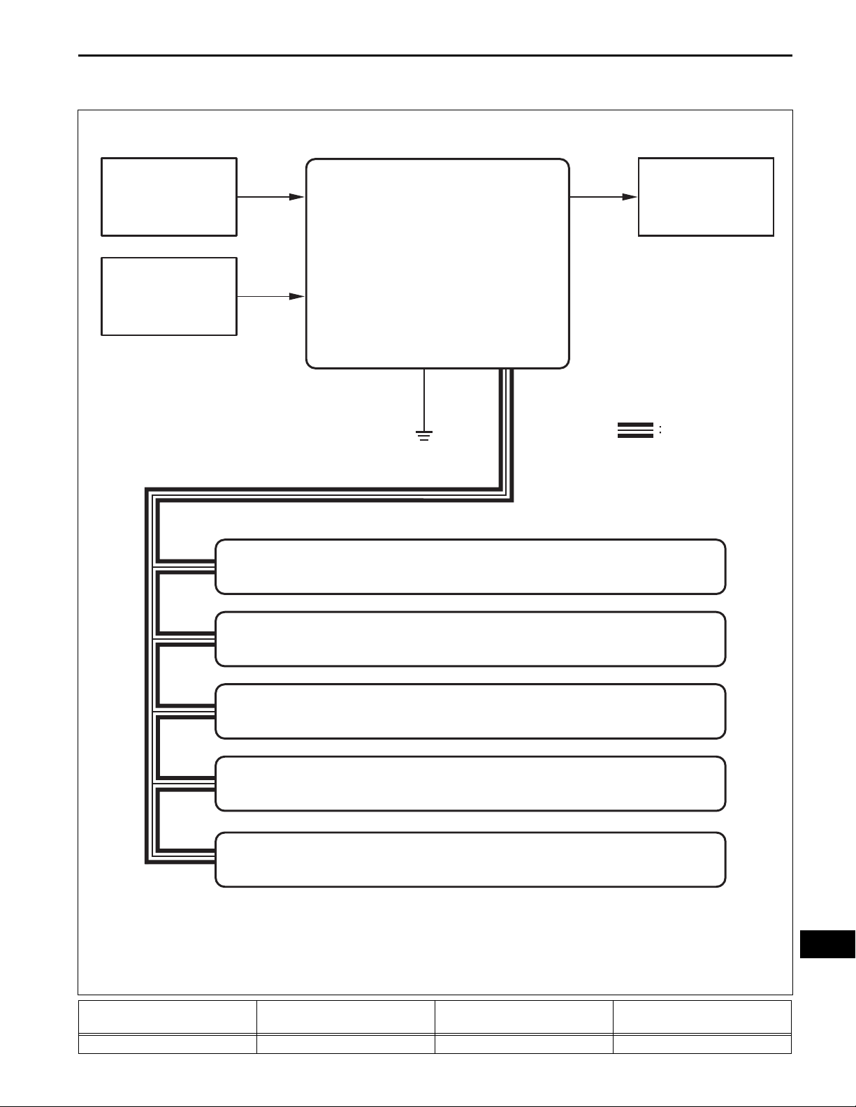
SYSTEM DIAGRAM
PS–7
Motor Rotation
Angle Sensor
Torque Sensor
Skid Control ECU
Power Steering ECU Assembly
- Motor Relay
- Power Source Relay
- Motor Current Sensor
- Temperature Sensor
EPS Motor
CAN
Steering Angle Sensor
Hybrid Vehicle Control ECU
Combination Meter
Main Body ECU (Instrument Panel J/B)
Transmitting ECU
(transmitter)
Hybrid Vehicle Control ECU Power Steering ECU Assembly T/M variation information signal CAN
Receiving ECU Signals Communication method
PS
B139367E01

PS–8
POWER STEERING – ELECTRONIC POWER STEERING SYSTEM
Transmitting ECU
(transmitter)
Hybrid Vehicle Control ECU Power Steering ECU Assembly Ready signal CAN
Hybrid Vehicle Control ECU Power Steering ECU Assembly Ambient temperature signal CAN
Hybrid Vehicle Control ECU Power Steering ECU Assembly Intake air temperature signal CAN
Hybrid Vehicle Control ECU Power Steering ECU Assembly
Hybrid Vehicle Control ECU Power Steering ECU Assembly
Hybrid Vehicle Control ECU Power Steering ECU Assembly TC terminal condition CAN
Skid Control ECU Power Steering ECU Assembly
Skid Control ECU Power Steering ECU Assembly Additional torque target signal CAN
Skid Control ECU Power Steering ECU Assembly Vehicle speed (SP1) status signal CAN
Skid Control ECU Power Steering ECU Assembly Target steering angle signal CAN
Skid Control ECU Power Steering ECU Assembly
Skid Control ECU Power Steering ECU Assembly Vehicle speed (SP1) signal CAN
Skid Control ECU Power Steering ECU Assembly Test mode signal CAN
Skid Control ECU Power Steering ECU Assembly VSC controlling signal CAN
Skid Control ECU Power Steering ECU Assembly ABS controlling signal CAN
Steering Angle Sensor Power Steering ECU Assembly
Steering Angle Sensor Power Steering ECU Assembly +B open circuit signal CAN
Steering Angle Sensor Power Steering ECU Assembly Sensor malfunction signal CAN
Steering Angle Sensor Power Steering ECU Assembly Steering angle signal CAN
Steering Angle Sensor Power Steering ECU Assembly
Steering Angle Sensor Power Steering ECU Assembly
Main Body ECU
(Instrument Panel J/B)
Power Steering ECU Assembly Skid Control ECU EPS pinion angle invalid signal CAN
Power Steering ECU Assembly Skid Control ECU
Power Steering ECU Assembly Skid Control ECU
Power Steering ECU Assembly Hybrid Vehicle Control ECU EPS idle up request signal CAN
Power Steering ECU Assembly Skid Control ECU EPS torque sensor value signal CAN
Power Steering ECU Assembly Skid Control ECU EPS pinion angle signal CAN
Power Steering ECU Assembly Skid Control ECU EPS assisting current signal CAN
Power Steering ECU Assembly Combination Meter EPS light ON request signal CAN
Power Steering ECU Assembly Combination Meter EPS diagnostic information signal CAN
Receiving ECU Signals Communication method
Engine variation information
signal
Vehicle destination information
signal
Output command value (to EPS)
signal
Target steering angle and
additional torque valid signal
Data continuity (valid/invalid)
signal
Zero point memory (in sensor)
valid/invalid signal
Zero point (stored in steering
angle sensor) signal
Power Steering ECU Assembly Vehicle model signal CAN
EPS assisting current invalid
signal
EPS torque sensor value invalid
signal
CAN
CAN
CAN
CAN
CAN
CAN
CAN
CAN
CAN
PS

POWER STEERING – ELECTRONIC POWER STEERING SYSTEM
PS–9
SYSTEM DESCRIPTION
1. DESCRIPTION
(a) The EPS system generates assist torque to assist
steering effort through the operation of the motor
installed on the power steering link assembly.
The direction and amount of power assistance are
determined by signals from the torque sensor, and
controlled in accordance with vehicle speed. As a
result, steering effort is controlled to be light during
low speed driving and moderately high during high
speed driving.
2. FUNCTIONS OF COMPONENTS
Components Function
Calculates degree of assistance needed based on steering torque and
vehicle speed. Drives the motor based on motor electric angle
Power Steering ECU Assembly
Torque Sensor Detects steering effort generated when the steering wheel is turned.
Power Steering Motor
Hybrid Vehicle Control ECU Transmits ready signal to the power steering ECU.
obtained from the motor rotation angle sensor.
Boosts battery voltage to generate motor drive voltage.
Restricts power assistance to protect the system if the motor and ECU
overheat.
Located coaxially with the rack shaft. Its rotation is converted to the
rectilinear motion of the steering rack via the ball screw nut and ball.
PS
PS–10
POWER STEERING – ELECTRONIC POWER STEERING SYSTEM
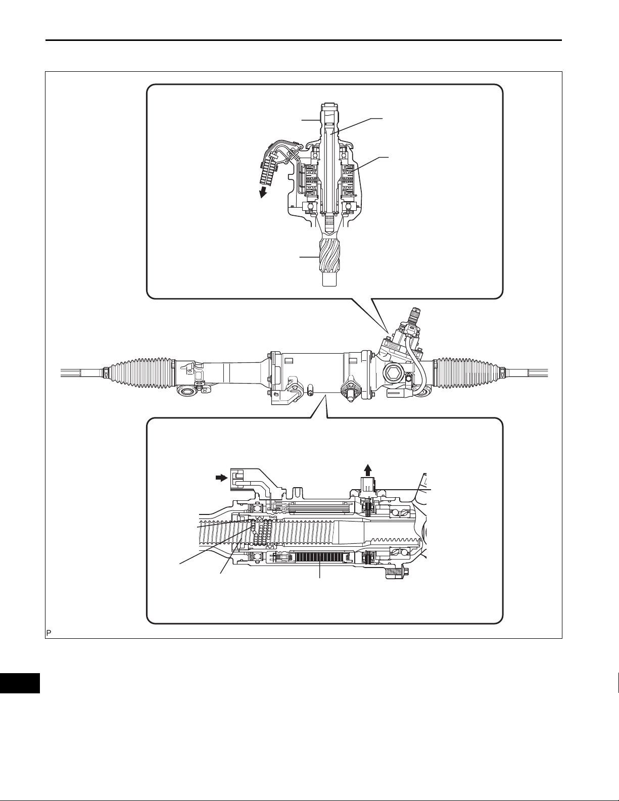
3. OPERATION EXPLANATION
Torque Sensor Portion:
Input Shaft
To Power Steering ECU
Assembly
Output Shaft
Torsion Bar
Torque Sensor
PS
Power Steering Motor Portion:
From Power
Steering ECU
Assembly
Ball Screw
Nut
Ball
Steering Rack
Power Steering Motor
To Power Steering ECU
Assembly
Motor Rotation
Angle Sensor
C106460E02
(a) The torque sensors is mounted on the input shaft to
the main shaft and on the output shaft to the pinion
shaft. The input and output shafts are joined by a
torsion bar.
(b) If the steering wheel is turned, the torsion bar twists,
resulting in a difference in the rotation angle
detected by the torque sensor. The power steering
ECU assembly calculates torque based on this
difference.

POWER STEERING – ELECTRONIC POWER STEERING SYSTEM
(c) The power steering ECU assembly calculates
proper assisting torque, according to vehicle speed,
based on the torque obtained in the previous step.
Then the ECU controls the motor drive circuit in
order to allow it to generate assisting torque.
(d) A ball screw nut is attached to the motor shaft. It
converts the rotational motion of the motor into the
rectilinear motion of the steering rack via the ball.
(e) The assisting force generated in the above process
will reduce the steering effort required by the driver.
PS–11
PS
PS–12
1
NEXT
2
NEXT
3
POWER STEERING – ELECTRONIC POWER STEERING SYSTEM
HOW TO PROCEED WITH
TROUBLESHOOTING
Perform troubleshooting according to the following flowchart.
HINT:
• For further details, see the page given.
• *: Use the intelligent tester.
VEHICLE BROUGHT TO WORKSHOP
CUSTOMER PROBLEM ANALYSIS
CHECK DTC AND FREEZE FRAME DATA*
NEXT
4
NEXT
5
6
NEXT
(a) Record the DTCs and freeze frame data.
CLEAR DTC AND FREEZE FRAME DATA*
PROBLEM SYMPTOM CONFIRMATION
SYMPTOM DOES NOT OCCUR (GO TO STEP
6)
SYMPTOM OCCURS (GO TO STEP 7)
SYMPTOM SIMULATION
PS
CHECK DTC*
7
(a) Recheck for DTCs.
HINT:
• Refer to the diagnostic trouble code chart if any DTCs
are output.
• If any CAN communication system DTCs are output,
perform troubleshooting on the CAN communication
system first (See page CA-7).
8
NEXT
9
NEXT
POWER STEERING – ELECTRONIC POWER STEERING SYSTEM
PROBLEM SYMPTOMS TABLE
DTC CHART
PS–13
• If communication to the power steering ECU
assembly is not established through the intelligent
tester, inspect terminals SIL of the DLC3 and power
steering ECU assembly, and inspect the IG circuit of
the power steering ECU assembly.
NORMAL SYSTEM CODE IS OUTPUT : GO T O
STEP 8
TROUBLE CODE IS OUTPUT: GO TO STEP 9
10
NEXT
11
NEXT
12
NEXT
13
NEXT
END
CIRCUIT INSPECTION*
IDENTIFICATION OF PROBLEM
REPAIR OR REPLACE
CONFIRMATION TEST
PS
PS–14
POWER STEERING – ELECTRONIC POWER STEERING SYSTEM
CALIBRATION
1. ROTATION ANGLE SENSOR VALUE INITIALIZATION
AND TORQUE SENSOR ZERO POINT CALIBRATION
NOTICE:
Clear the rotation angle sensor calibration value,
initialize the rotation angle sensor value, and
calibrate the torque sensor zero point if any of the
following has occurred:
• The power steering ECU assembly has been
replaced.
• The power steering link assembly has been
replaced.
• Steering effort differs between left and right.
(a) Inspection before calibration
(1) Connect the intelligent tester (with CAN VIM) to
the DLC3.
(2) Turn the power switch on (IG).
(3) Turn the intelligent tester on.
(4) Select "IG SUPPLY" from the data list.
(5) Check the IG power supply voltage on the tester
screen.
PS
DLC3
Intelligent Tester
C131977E01
Tester Display Measurement Item/Range Inspection Condition Reference Value
IG SUPPLY
ECU power source voltage/
Min.: 0 V, Max.: 25.5 V
Power switch on (IG) 10 to 14 V
Standard voltage:
10 to 14 V
NOTICE:
If the IG power supply voltage is 10 V or less,
calibration cannot be performed. In this case,
charge or replace the battery, and then
perform calibration.

DLC3
POWER STEERING – ELECTRONIC POWER STEERING SYSTEM
Intelligent Tester
C131977E01
PS–15
(b) Rotation angle sensor calibration value clear,
rotation angle sensor value initialization, and torque
sensor zero point calibration.
NOTICE:
• If DTC C1516 (Torque Sensor Zero Point
Adjustment Incomplete) is stored, the torque
sensor zero point cannot be calibrated. Clear
the DTC before starting calibration.
• If DTC C1526 (Rotation Angle Sensor
Initialization Incomplete) is stored, the
rotation angle sensor value cannot be
initialized. Clear the DTC before starting
initialization.
(1) Connect the intelligent tester (with CAN VIM) to
the DLC3.
(2) Turn the power switch on (IG).
(3) Turn the intelligent tester on.
(4) Select "TRQ SENSOR ADJ".
(5) Follow the procedures on the tester display to
clear the rotation angle sensor calibration value,
initialize the rotation angle sensor value, and
calibrate the torque sensor zero point.
NOTICE:
• When initializing the rotation angle sensor
value, observe the following to stabilize
sensor voltage:
After turning the power switch on (IG),
wait for at least 2.5 seconds before
turning the steering wheel. Do not turn the
steering wheel quickly.
• The steering wheel will vibrate during
torque sensor zero point calibration. Do
not touch the steering wheel while it is
vibrating or for 2 seconds after it stops.
PS

PS–16
POWER STEERING – ELECTRONIC POWER STEERING SYSTEM
PROBLEM SYMPTOMS TABLE
ELECTRONIC POWER STEERING SYSTEM
Symptom Suspected Area See page
1. Front tires (Improperly inflated, unevenly worn) TW-3
2. Front wheel alignment (Incorrect) SP-4
3. Front suspension SP-24
4. Power steering link assembly PS-61
Steering is heavy.
Steering effort differs between right and left, or is
uneven.
While driving, steering effort does not change in
accordance with vehicle speed, or the steering wheel
does not return to its centered position easily.
Friction sounds occur when turning the steering wheel
during low speed driving.
High-pitched sounds (squeaking) occur when turning
the steering wheel slowly with the vehicle stopped.
The steering wheel vibrates and noise occurs when
turning the steering wheel with the vehicle stopped.
PS warning light remains on. PS warning light remains on PS-50
PS warning light does not come on. PS warning light does not come on PS-54
5. Steering column assembly SR-35
6. Battery and power source system -
7. Power source voltage of power steering ECU assembly PS-50
8. Power steering ECU assembly PS-68
9. Vehicle condition (The steering wheel is turned from left to
right repeatedly with the vehicles stopped or a heavy load is
continuously applied to the vehicle)
1. Power steering ECU assembly (Steering center point is not
recorded correctly)
2. Front tires (Improperly inflated, unevenly worn) TW-3
3. Front wheel alignment (Incorrect) SP-4
4. Front suspension SP-24
5. Power steering link assembly PS-61
6. Steering column assembly SR-35
7. Power steering ECU assembly PS-68
1. Speed sensor BC-273
2. Skid control ECU BC-289
3. Power steering link assembly PS-61
4. Power steering ECU assembly PS-68
1. Power steering link assembly PS-61
2. Power steering ECU assembly PS-68
Power steering link assembly PS-61
1. Power steering link assembly PS-61
2. Steering column assembly PS-68
-
PS-13
PS
POWER STEERING – ELECTRONIC POWER STEERING SYSTEM
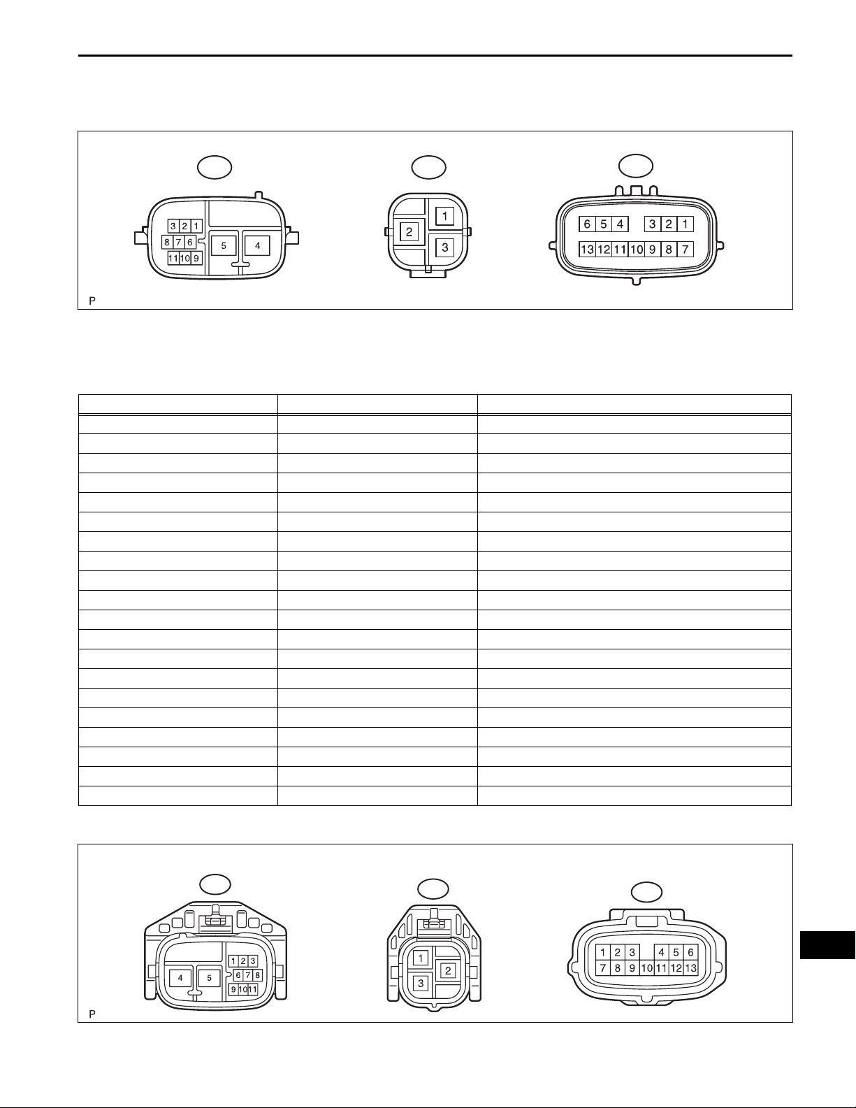
TERMINALS OF ECU
1. TERMINALS OF ECU
PS–17
A66 A68
A67
HINT:
The power steering ECU assembly uses waterproof
connectors. Therefore, voltage or waveforms cannot be
checked with the connectors connected to the vehicle.
Terminal No. (Symbols) Wiring Color Terminal Description
A66-2 (CANH) B High-level CAN bus line
A66-3 (CANL) W Low-level CAN bus line
A66-4 (PIG) W Power source
A66-5 (PGND) B Power ground
A66-9 (IG) O IG power source
A67-1 (RZG) W Rotation angle sensor power source circuit ground
A67-2 (SRZG) BR Rotation angle sensor shield ground
A67-3 (RZV) G Rotation angle sensor power source
A67-4 (TRQV) P Torque sensor power source
A67-6 (TQG1) L Torque sensor power source circuit ground
A67-7 (RZSN) B SIN phase input signal (Rotation angle sensor)
A67-8 (RZCS) R COS phase input signal (Rotation angle sensor)
A67-9 (INSN) B SIN phase input signal (Torque sensor input shaft side)
A67-10 (INCS) R COS phase input signal (Torque sensor input shaft side)
A67-11 (OUSN) W SIN phase input signal (Torque sensor output shaft side)
A67-12 (OUCS) G COS phase input signal (Torque sensor output shaft side)
A67-13 (TQG2) Y Torque sensor detection circuit ground
A68-1 (V) R V phase motor output
A68-2 (U) B U phase motor output
A68-3 (W) W W phase motor output
C116647E02
A66
2. INSPECT WIRE HARNESS SIDE CONNECTOR
A68
A67
PS
C116648E02
PS–18
Terminal No. (Symbols) Wiring Color Terminal Description Condition Specified Conditi on
A66-4 (PIG) - A66-5 (PGND) W - B Power source Always 10 to 14 V
A66-5 (PGND) - Body ground B - Body ground Power ground Always Below 1 Ω
A66-9 (IG) - A66-5 (PGND) O - B IG power source Power switch on (IG) 10 to 14 V
A68-2 (U) - A68-3 (W)/A68-1 (V) B - W/R U phase motor output Always Below 1 Ω
A68-3 (W) - A68-2 (U)/A68-1 (V) W - BR W phase motor output Always Below 1 Ω
A68-1 (V) - A68-2 (U)/ A68-3 (W) R - B/W V phase motor output Always Below 1 Ω
POWER STEERING – ELECTRONIC POWER STEERING SYSTEM
DIAGNOSIS SYSTEM
CG
SG
CANH
SIL
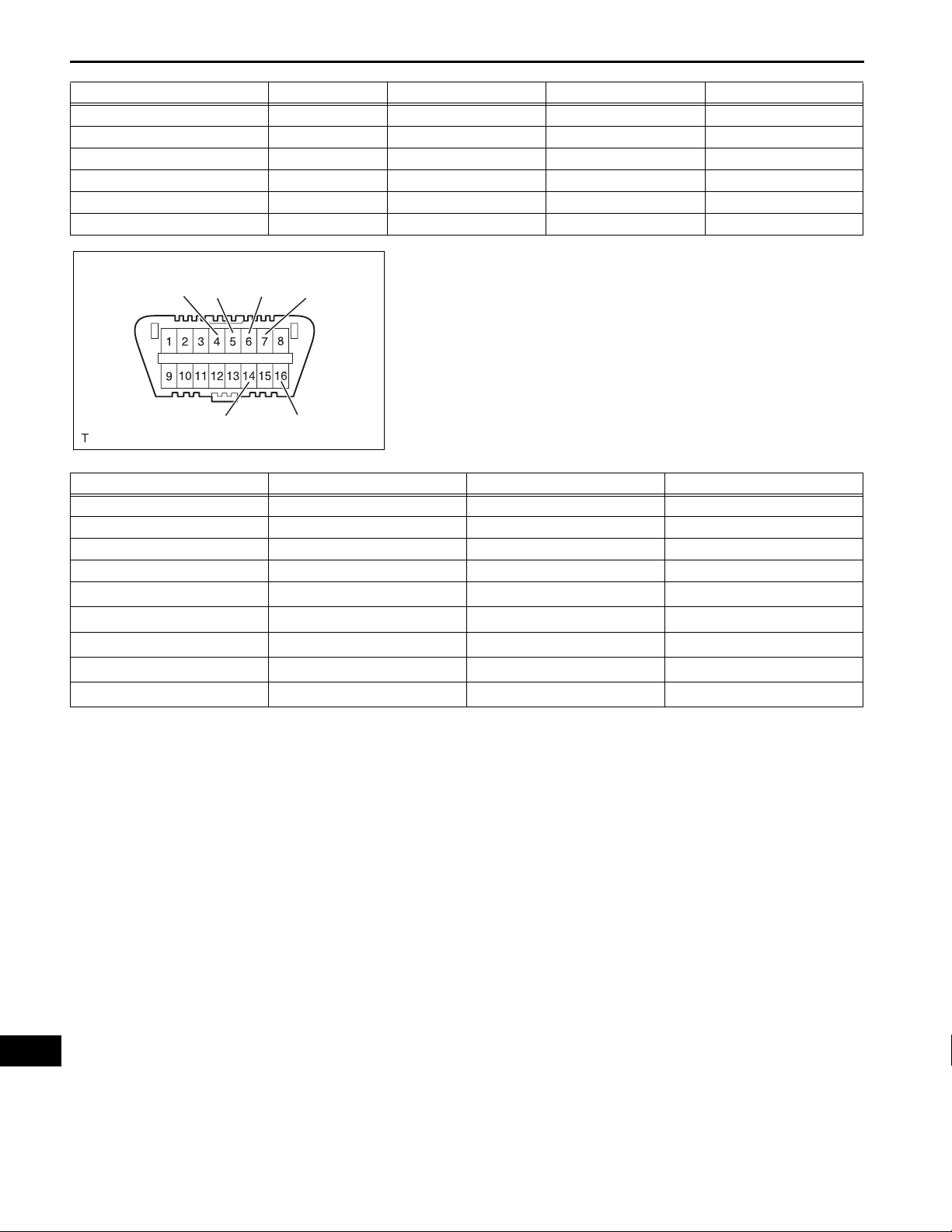
1. CHECK DLC3
(a) The vehicle's ECU uses ISO 15765-4 for
communication protocol. The terminal arrangement
of the DLC3 complies with SAE J1962 and matches
the ISO 15765-4 format.
CANL
Symbols (Terminal No.) Terminal Description Condition Specified Condition
SIL (7) - SG (5) Bus "+" line During transmission Pulse generation
CG (4) - Body ground Chassis ground Always Below 1 Ω
SG (5) - Body ground Signal ground Always Below 1 Ω
BAT (16) - Body ground Battery positive Always 10 to 14 V
CANH (6) - CANL (14) CAN bus line
CANH (6) - CG (4) HIGH-level CAN bus line
CANL (14) - CG (4) LOW-level CAN bus line
CANH (6) - BAT (16) HIGH-level CAN bus line
CANL (14) - BAT (16) LOW-level CAN bus line
BAT
H100769E16
Power switch off
Power switch off
Power switch off
Power switch off
Power switch off
*
*
*
*
*
54 to 69 Ω
200 Ω or higher
200 Ω or higher
6 kΩ or higher
6 kΩ or higher
NOTICE:
*: Before measuring the resistance, leave the
vehicle as is for at least 1 minute and do not
operate the power switch, any other switches or
the doors.
If the result is not as specified, the DLC3 may have
a malfunction. Repair or replace the harness and
connector.
PS
DLC3
POWER STEERING – ELECTRONIC POWER STEERING SYSTEM
Intelligent Tester
C131977E01
B150816
(b) Connect the cable of the intelligent tester (with CAN
VIM) to the DLC3, turn the power switch on (IG) and
attempt to use the intelligent tester. If the screen
displays a communication error message, a
problem exists in the vehicle side or tester side.
HINT:
• If communication is normal when the tool is
connected to another vehicle, inspect the DLC3
on the original vehicle.
• If communication is still impossible when the tool
is connected to another vehicle, the problem is
probably in the tool itself. Consult the Service
Department listed in the tool's instruction manual.
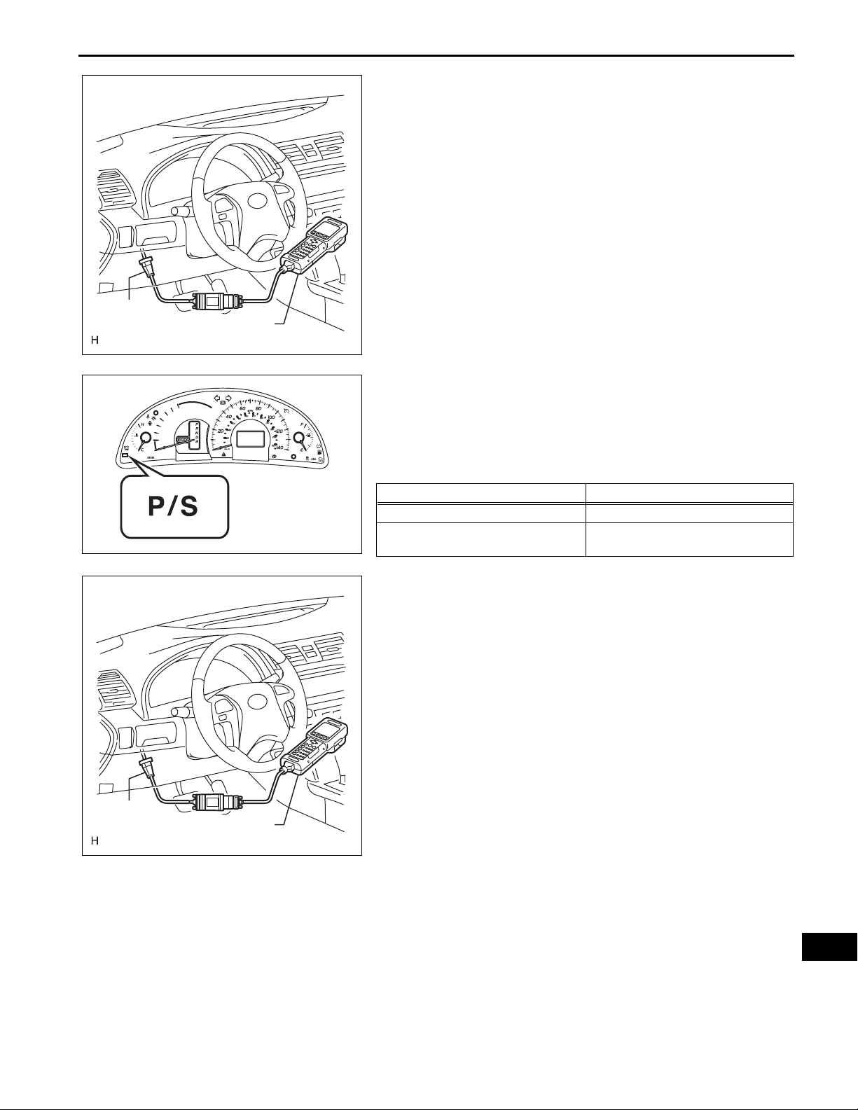
2. P/S WARNING LIGHT
(a) Check that the PS warning light comes on when the
power switch is turned on (IG) and goes off in
approximately 3 seconds.
If the warning light does not come on or remains on,
inspect the PS warning light circuit.
Trouble Area See Procedure
PS warning light circuit (Remains on) PS-50
PS warning light circuit (Does not come
on)
PS-54
PS–19
DLC3
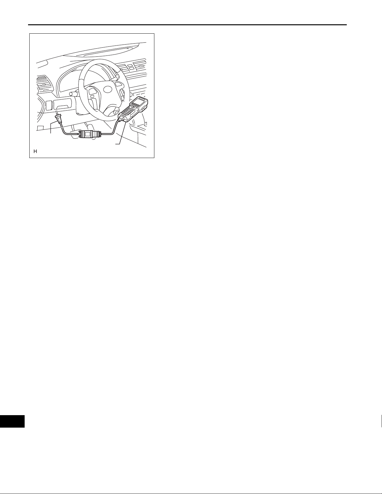
DTC CHECK / CLEAR
1. CHECK FOR DTCs
(a) Connect the intelligent tester (with CAN VIM) to the
DLC3.
(b) Turn the power switch on (IG).
(c) Turn the intelligent tester on.
(d) Read the DTCs by following the display on the
intelligent tester.
HINT:
Refer to the intelligent tester operator's manual for
further details.
Intelligent Tester
C131977E01
PS
PS–20
DLC3
POWER STEERING – ELECTRONIC POWER STEERING SYSTEM
2. CLEAR DTCs
(a) Connect the intelligent tester (with CAN VIM) to the
DLC3.
(b) Turn the power switch on (IG).
(c) Turn the intelligent tester on.
(d) Clear the DTCs by following the display on the
intelligent tester.
HINT:
Refer to the intelligent tester operator's manual for
further details.
Intelligent Tester
C131977E01
PS
POWER STEERING – ELECTRONIC POWER STEERING SYSTEM
FREEZE FRAME DATA
1. FREEZE FRAME DATA
NOTICE:
• It is difficult to show the specified values
(judgement values) clearly because freeze frame
data values change significantly due to
differences in measurement conditions,
surroundings, or vehicle conditions. For this
reason, there may be a problem even when the
values are within specifications.
• T urn the power switch on (IG) and p ark the vehicle
on level ground. Check the freeze frame data by
using the intelligent tester.
(a) Connect the intelligent tester (with CAN VIM) to the
DLC3.
(b) Turn the power switch on (IG) and check the freeze
frame data by following the prompts on the
intelligent tester's display screen.
PS–21
DLC3
Intelligent Tester
Tester Display Item Description/Range Inspection Condition Reference Value
SPD
ENGINE REV
MOTOR ACTUAL
COMMAND VALUE
STR ANGL VEL
THERMISTOR TEMP
PIG SUPPLY
IG SUPPLY
STR SENS SIG
TRQ1
C131977E01
Vehicle speed from meter/
Min.: 0 km/h (0 mph), Max.: 300
km/h (186 mph)
Engine revolution/
Min.: 0 rpm, Max.: 12.800 rpm
Amount of current to motor/
Min.: -128 A, Max.: 127 A
Demanded amount of current to
motor/
Min.: -128 A, Max.: 127 A
Steering angle speed/
Min.: -4.096 deg/sec, Max.: 4.064
deg/sec
ECU substrate temperature/
Min.: -50°C, Max.: 205°C
Power source voltage to activate
motor/
Min.: 0 V, Max.: 25.5 V
ECU power source voltage/
Min.: 0 V, Max.: 25.5 V
Steering angle sensor signal
status/
OK or NG
Torque sensor 1 rotation angle/
Min.: 0 deg, Max.: 360 deg
1. Vehicle is stopped
2. V ehicle is driven at a constant
speed
Engine is running at a constant
speed
Power steering is in operation
Power steering is in operation
Steering wheel is turned
Power switch on (IG) -
Power steering is in operation 10 to 14 V
Power switch on (IG) 10 to 14 V
--
Steering wheel is turned
1. 0 km/h (0 mph)
2. No significant fluctuation
No significant fluctuation
Value changes in proportion to
steering effort
Value changes in proportion to
steering effort
Value changes in proportion to
steering speed
Value changes from 0 to 360°
every 22.5° of steering angle
PS

PS–22
Tester Display Item Description/Range Inspection Condition Reference Value
TRQ2
TRQ1 ZERO VAL
TRQ2 ZERO VAL
STEERING TORQU
MOTOR ROTATE
COMMAND VALUE 2
PIG2 VOLTAGE
MOTOR VOLTAGE
MTR TERMINAL (U)
MTR TERMINAL (V)
MTR TERMINAL (W)
IG ON/OFF TIMES
MTR OVERHEAT
MTR LOW POWER
ENG REV INTER
STR ANGL INTER
SPD SIG INVALID
BATTERY VOLTAGE
PS ASSIST SIG
# CODES
POWER STEERING – ELECTRONIC POWER STEERING SYSTEM
Torque sensor 2 rotation angle/
Min.: 0 deg, Max.: 360 deg
Zero point value of torque sensor
1/
Min.: 0 deg, Max.: 360 deg
Zero point value of torque sensor
2/
Min.: 0 deg, Max.: 360 deg
Steering torque/
Min.: -7.0 N*m, Max.: 7.0 N*m
Motor rotation angle/
Min.: 0 deg, Max.: 360 deg
Demanded amount of current to
motor 2/
Min.: -128 A, Max.: 127 A
Motor drive voltage/
Min.: 0 V, Max.: 64 V
Motor power source voltage/
Min.: 0 V, Max.: 64 V
Motor terminal voltage (U phase)/
Min.: 0 V, Max.: 64 V
Motor terminal voltage (V phase)/
Min.: 0 V, Max.: 64V
Motor terminal voltage (W phase)/
Min.: 0 V, Max.: 64 V
Number of times IG switch is
turned on after DTC detection/
Min.: 0 time, Max.: 255 times
Continuous overheat prevention
control record/
REC or UNREC
PIG power source voltage drop
record/
REC or UNREC
Record of power revolution signal
interruption/
REC or UNREC
Record of steering angle sensor
signal interruption/
REC or UNREC
Record of vehicle speed signal
invalid/
REC or UNREC
Battery voltage/
Min.: 0 V, Max.: 25.5 V
Power steering assist signal/
ON or OFF
Number of detected DTCs when
freeze frame data is stored/
Min.: 0, Max.: 255
Steering wheel is turned
Steering wheel is not turned
(without load)
Steering wheel is not turned
(without load)
Steering wheel is turned
Steering wheel is turned
--
Power steering is in operation 27 to 34 V
Power steering is in operation 27 to 34 V
Power steering is in operation 0 to 34 V
Power steering is in operation 0 to 34 V
Power steering is in operation 0 to 34 V
--
--
--
--
--
--
- 10 to 14 V
Power switch on (IG) -
--
Value changes from 0 to 360°
every 22.5° of steering angle
Values differ depending on
vehicle
Values differ depending on
vehicle
Value changes in proportion to
steering effort
Value changes from 0 to 360°
every 5° of steering angle
PS

POWER STEERING – ELECTRONIC POWER STEERING SYSTEM
FAIL-SAFE CHART
If a problem occurs in the electronic power steering system,
the PS warning light will come on in the combination meter
and steering power assistance will be stopped, fixed at a
particular point, or decreased simultaneously to protect the
system.
DTC No. Malfunction Fail-safe
C1511
C1512
C1513
C1521
C1522
C1523
C1524
C1528 Motor Rotation Angle Sensor Malfunction
C1531
C1532
C1555 Motor Relay Welding Failure
C1533 ECU Malfunction
C1534 ECU Malfunction
C1541 Vehicle Speed Signal Malfunction
U0129 Lost Communication With Skid Control ECU
Torque Sensor Circuit Malfunction
Motor Circuit Malfunction
ECU Malfunction
Power assistance stops.
System overheat prevention control continues
without using the substrate temperature
sensor.
Torque sensor zero point and rotation angle
sensor calibration value are set to the default
values.
Amount of power assistance is fixed for a
speed of 100 km/h (62 mph).
PS–23
HINT:
The amount of power assistance may be decreased to
prevent the motor and ECUs from overheating if the steering
wheel is continuously turned when the vehicle is either
stopped or driven at a low speed, or if the steering wheel is
kept at either full lock position for a long time. In that case, the
amount of power assistance will return to normal if the
steering wheel is not turned for approximately 10 minutes
with the engine idling.
PS
PS–24
POWER STEERING – ELECTRONIC POWER STEERING SYSTEM
DATA LIST / ACTIVE TEST
1. DATA LIST
HINT:
By accessing the data list displayed on the intelligent
tester, values of switches, sensors and other related
parts can be checked without removing any parts.
Reading the data list is the first step in troubleshooting
and is one method to shorten labor time.
(a) Connect the intelligent tester (with CAN VIM) to the
DLC3.
(b) Turn the power switch on (IG).
(c) Operate the intelligent tester according to the steps
on the display and select the data list.
PS
DLC3
Intelligent Tester
Tester Display Measurement Item/Range Normal Condition Reference Value
SPD
ENGINE REV
MOTOR ACTUAL
COMMAND VALUE
STR ANGL VEL
THERMISTOR TEMP
PIG SUPPLY
IG SUPPLY
STR SENS SIG
TRQ1
TRQ2
TRQ1 ZERO VAL
C131977E01
Vehicle speed from meter/
Min.: 0 km/h (0 mph), Max.: 300
km/h (186 mph)
Engine revolution/
Min.: 0 rpm, Max.: 12.800 rpm
Amount of current to motor/
Min.: -128 A, Max.: 127 A
Demanded amount of current to
motor/
Min.: -128 A, Max.: 127 A
Steering angle speed/
Min.: -4.096 deg/sec, Max.: 4.064
deg/sec
ECU substrate temperature/
Min.: -50°C, Max.: 205°C
Power source voltage to activate
motor/
Min.: 0 V, Max.: 25.5 V
ECU power source voltage/
Min.: 0 V, Max.: 25.5 V
Steering angle sensor signal
status/
OK or NG
Torque sensor 1 rotation angle/
Min.: 0 deg, Max.: 360 deg
Torque sensor 2 rotation angle/
Min.: 0 deg, Max.: 360 deg
Zero point value of torque sensor
1/
Min.: 0 deg, Max.: 360 deg
1. Vehicle is stopped
2. V ehicle is driven at a const ant
speed
Engine is running at a constant
speed
Power steering is in operation
Power steering is in operation
Steering wheel is turned
Power switch on (IG) -
Power steering is in operation 10 to 14 V
Power switch on (IG) 10 to 14 V
--
Steering wheel is turned
Steering wheel is turned
Steering wheel is not turned
(without load)
1. 0 km/h (0 mph)
2. No significant fluctuation
No significant fluctuation
Value changes in proportion to
steering effort
Value changes in proportion to
steering effort
Value changes in proportion to
steering speed
Value changes from 0 to 360°
every 22.5° of steering angle
Value changes from 0 to 360°
every 22.5° of steering angle
Values differ depending on
vehicle

Tester Display Measurement Item/Range Normal Condition Reference Value
TRQ2 ZERO VAL
STEERING TORQU
MOTOR ROTATE
COMMAND VALUE 2
PIG2 VOLTAGE
MOTOR VOLTAGE
MTR TERMINAL (U)
MTR TERMINAL (V)
MTR TERMINAL (W)
IG ON/OFF TIMES
MTR OVERHEAT
MTR LOW POWER
ENG REV INTER
STR ANGL INTER
SPD SIG INVALID
BATTERY VOLTAGE
PS ASSIST SIG
# CODES
POWER STEERING – ELECTRONIC POWER STEERING SYSTEM
Zero point value of torque sensor
2/
Min.: 0 deg, Max.: 360 deg
Steering torque/
Min.: -7.0 N*m, Max.: 7.0 N*m
Motor rotation angle/
Min.: 0 deg, Max.: 360 deg
Demanded amount of current to
motor 2/
Min.: -128 A, Max.: 127 A
Motor drive voltage/
Min.: 0 V, Max.: 64 V
Motor power source voltage/
Min.: 0 V, Max.: 64 V
Motor terminal voltage (U phase)/
Min.: 0 V, Max.: 64 V
Motor terminal voltage (V phase)/
Min.: 0 V, Max.: 64V
Motor terminal voltage (W phase)/
Min.: 0 V, Max.: 64 V
Number of times IG switch is
turned on after DTC detection/
Min.: 0 time, Max.: 255 times
Continuous overheat prevention
control record/
REC or UNREC
PIG power source voltage drop
record/
REC or UNREC
Record of power revolution signal
interruption/
REC or UNREC
Record of steering angle sensor
signal interruption/
REC or UNREC
Record of vehicle speed signal
invalid/
REC or UNREC
Battery voltage/
Min.: 0 V, Max.: 25.5 V
Power steering assist signal/
ON or OFF
Number of detected DTCs when
freeze frame data is stored/
Min.: 0, Max.: 255
Steering wheel is not turned
(without load)
Steering wheel is turned
Steering wheel is turned
--
Power steering is in operation 27 to 34 V
Power steering is in operation 27 to 34 V
Power steering is in operation 0 to 34 V
Power steering is in operation 0 to 34 V
Power steering is in operation 0 to 34 V
--
--
--
--
--
--
- 10 to 14 V
Power switch on (IG) -
--
Values differ depending on
vehicle
Value changes in proportion to
steering effort
Value changes from 0 to 360°
every 5° of steering angle
PS–25
PS

PS
PS–26
POWER STEERING – ELECTRONIC POWER STEERING SYSTEM
DIAGNOSTIC TROUBLE CODE CHART
HINT:
If a trouble code is displayed during the DTC check, check
the circuit indicated by the DTC. For details of each code, turn
to the page for the respective DTC code in the DTC chart
ELECTRONIC POWER STEERING SYSTEM DIAGNOSTIC TROUBLE CODE CHART:
DTC Code Detection Item Trouble Area See page
1. Wire harness
C1511 Torque Sensor Circuit Malfunction
C1512 Torque Sensor Circuit Malfunction
C1513 Torque Sensor Circuit Malfunction
C1515 Torque Sensor Zero Point Adjustment Undone - PS-28
C1516
C1521 Motor Circuit Malfunction Power steering ECU assembly PS-33
C1522 Motor Circuit Malfunction Power steering ECU assembly PS-33
C1523 Motor Circuit Malfunction
C1524 Motor Circuit Malfunction
C1525 Rotation Angle Sensor Initialization Undone - PS-28
C1526 Rotation Angle Sensor Initialization Incomplete - PS-30
C1528 Motor Rotation Angle Sensor Malfunction
C1531 ECU Malfunction Power steering ECU assembly PS-33
C1532 ECU Malfunction Power steering ECU assembly PS-33
C1533 ECU Malfunction Power steering ECU assembly PS-33
C1534 ECU Malfunction Power steering ECU assembly PS-33
C1541 Vehicle Speed Signal Malfunction
C1551 IG Power Supply Voltage Malfunction Power steering ECU assembly PS-44
C1552 PIG Power Supply Voltage Malfunction
C1554 Power Supply Relay Failure Power steering ECU assembly PS-33
C1555 Motor Relay Welding Failure Power steering ECU assembly PS-33
C1581 Assist Map Number Un-Writing
U0073 Control Module Communication Bus OFF CAN communication system PS-49
Torque Sensor Ze ro Point Adjustment
Incomplete
2. Torque sensor (built into power steering link
assembly)
3. Power steering ECU assembly
1. Wire harness
2. Torque sensor (built into power steering link
assembly)
3. Power steering ECU assembly
1. Wire harness
2. Torque sensor (built into power steering link
assembly)
3. Power steering ECU assembly
- PS-30
1. Wire harness
2. Power steering motor (built into power
steering link assembly)
3. Power steering ECU assembly
1. Wire harness
2. Power steering motor (built into power
steering link assembly)
3. Power steering ECU assembly
1. Motor rotation angle sensor (built into power
steering link assembly)
2. Wire harness
3. Power steering earth wire
4. Power steering ECU assembly
1. Speed sensor circuit
2. Skid control ECU
3. CAN communication system
4. Power steering ECU assembly
1. EPS fuse
2. Wire harness
3. Power steering ECU assembly
1. Hybrid vehicle control ECU
2. Main body ECU (Instrument panel J/B)
3. Power steering ECU assembly
PS-24
PS-24
PS-24
PS-35
PS-35
PS-38
PS-42
PS-45
PS-47

POWER STEERING – ELECTRONIC POWER STEERING SYSTEM
DTC Code Detection Item Trouble Area See page
U0100 Lost Communication with ECM/PCM "A"
U0129 Lost Communication with Skid Control ECU
U0293 Lost Communication with HV ECU
1. CAN communication system
2. Hybrid vehicle control ECU
1. CAN communication system
2. Skid control ECU
1. CAN communication system
2. Hybrid vehicle control ECU
PS–27
PS-49
PS-49
PS-49
PS

PS–28
POWER STEERING – ELECTRONIC POWER STEERING SYSTEM
DTC C1511 Torque Sensor Circuit Malfunction
DTC C1512 Torque Sensor Circuit Malfunction
DTC C1513 Torque Sensor Circuit Malfunction
DESCRIPTION
The torque sensor converts rotation torque input to the steering wheel into an electrical signal and sends
it to the ECU. Based on this signal, the ECU detects steering effort.
DTC No. Detection Item Trouble Area
• Wire harness
C1511 Torque sensor (TRQ1) signal error or stop
C1512 Torque sensor (TRQ2) signal error or stop
C1513 Deviation between torque sensors
• Torque sensor (built into power steering link
assembly)
• Power steering ECU assembly
• Wire harness
• Torque sensor (built into power steering link
assembly)
• Power steering ECU assembly
• Wire harness
• Torque sensor (built into power steering link
assembly)
• Power steering ECU assembly
PS

POWER STEERING – ELECTRONIC POWER STEERING SYSTEM
WIRING DIAGRAM
A71
Torque Sensor
PS–29
A67
Power Steering ECU
Assembly
INCS
INSN
TRQV
OUCS
OUSN
TQG2
TQG1
1
2
4
5
6
7
8
R
G
W
10
INCS
B
P
Y
L
9
4
12
11
13
6
INSN
TRQV
OUCS
OUSN
TQG2
TQG1
C106487E10
PS

PS–30
POWER STEERING – ELECTRONIC POWER STEERING SYSTEM
INSPECTION PROCEDURE
CHECK HARNESS AND CONNECTOR (POWER STEERING ECU ASSEMBLY - TORQUE
1
SENSOR)
Wire Harness Side Connector Front View:
A71
Torque Sensor
INSN
TRQV
INCS
OUCS
OUSN
TQG1
TQG2
A67
Power Steering ECU Assembly
TQG1
TQG2
INSN
INCS
OUSN
TRQV
OUCS
C116652E02
(a) Disconnect the A67 connector from the power steering
ECU assembly.
(b) Disconnect the A71 connector from the torque sensor.
(c) Measure the resistance according to the value(s) in the
table below.
Standard resistance
Tester connection
(Symbols)
A71-1 (INCS) - A67-10 (INCS) Always Below 1 Ω
A71-2 (INSN) - A67-9 (INSN) Always Below 1 Ω
A71-4 (TRQV) - A67-4 (TRQV) Always Below 1 Ω
A71-5 (OUCS) - A67-12
(OUCS)
A71-6 (OUSN) - A67-11
(OUSN)
A71-7 (TQG2) - A67-13
(TQG2)
A71-8 (TQG1) - A67-6 (TQG1) Always Below 1 Ω
A71-1 (INCS) - Body ground Always 10 kΩ or higher
A71-2 (INSN) - Body ground Always 10 kΩ or higher
A71-4 (TRQV) - Body ground Always 10 kΩ or higher
A71-5 (OUCS) - Body ground Always 10 kΩ or higher
A71-6 (OUSN) - Body ground Always 10 kΩ or higher
A71-7 (TQG2) - Body ground Always 10 kΩ or higher
A71-8 (TQG1) - Body ground Always 10 kΩ or higher
Condition Specified condition
Always Below 1 Ω
Always Below 1 Ω
Always Below 1 Ω
PS
OK
INSPECT POWER STEERING LINK ASSEMBLY (TORQUE SENSOR)
2
Torque Sensor:
A71
C102953E11
NG
REPAIR OR REPLACE HARNESS OR
CONNECTOR
(a) Measure the resistance according to the value(s) in the
table below.
Standard resistance
Tester connection
(Symbols)
A71-1 (INCS) - A71-7 (TQG2) Always 90 to 170 Ω
A71-2 (INSN) - A71-7 (TQG2) Always 300 to 430 Ω
A71-4 (TRQV) - A71-8 (TQG1) Always 4 to 14 Ω
A71-5 (OUCS) - A71-7 (TQG2) Always 90 to 170 Ω
A71-6 (OUSN) - A71-7 (TQG2) Always 300 to 430 Ω
Condition Specified condition

POWER STEERING – ELECTRONIC POWER STEERING SYSTEM
NOTICE:
If replacing the power steering link assembly, clear
the rotation angle sensor calibration value, initialize
the rotation angle sensor value, and calibrate the
torque sensor zero point (See page PS-13).
PS–31
OK
3
NEXT
4
NEXT
5
NG
REPLACE POWER STEERING ECU ASSEMBLY
(a) Replace the power steering ECU assembly (See page
PS-68).
INITIALIZE ROTATION ANGLE SENSOR AND CALIBRATE TORQUE SENSOR ZERO
POINT
(a) Initialize the rotation angle sensor value and calibrate the
torque sensor zero point (See page PS-13).
RECONFIRM DTC
REPLACE POWER STEERING LINK
ASSEMBLY (See page PS-58)
END
(a) Check for DTCs (See page PS-17).
Result
DTC Condition Proceed to
DTC is not output A
DTC C1511, C1512, or C1513 is output B
NOTICE:
If replacing the power steering link assembly, clear
the rotation angle sensor calibration value, initialize
the rotation angle sensor value, and calibrate the
torque sensor zero point (See page PS-13).
B
A
REPLACE POWER STEERING LINK
ASSEMBLY (See page PS-58)
PS

PS–32
POWER STEERING – ELECTRONIC POWER STEERING SYSTEM
DTC C1515 Torque Sensor Zero Point Adjustment Undone
DTC C1525 Rotation Angle Sensor Initialization Undone
DESCRIPTION
These DTCs do not indicate a malfunction. The power steering ECU assembly outputs these DTCs when
it determines that rotation angle sensor value initialization and torque sensor zero point calibration have
not been performed. When IG terminal voltage is 9 V or less, rotation angle sensor initialization and
torque sensor zero point calibration cannot be performed.
DTC No. DTC Detection Condition Procedure
C1515
C1525
This DTC is detected when torque sensor zero point
calibration has not been performed.
This DTC is detected when rotation angle sensor value
initialization has not been performed.
INSPECTION PROCEDURE
There is no malfunction if this DTC is not output again
after performing zero point calibration.
There is no malfunction if this DTC is not output again
after performing rotation angle sensor value
initialization.
1
NEXT
2
INITIALIZE ROTATION ANGLE SENSOR AND CALIBRATE TORQUE SENSOR ZERO
POINT
(a) Initialize the rotation angle sensor and calibrate the
torque sensor zero point (See page PS-13).
RECONFIRM DTC
(a) Check for DTCs (See page PS-17).
Result
Result Proceed to
DTCs are still output after performing rotation angle
sensor value initialization and steering zero point
calibration 3 times.
DTCs are still output after performing rotation angle
sensor value initialization and steering zero point
calibration once or twice.
Normal system code is output. C
A
B
HINT:
Replace the power steering ECU assembly if DTCs are
still output after performing rotation angle sensor value
initialization and steering zero point calibration 3 times.
PS
B
C
Go to step 1
END
A

3
NEXT
4
NEXT
5
POWER STEERING – ELECTRONIC POWER STEERING SYSTEM
REPLACE POWER STEERING ECU ASSEMBLY
(a) Replace the power steering ECU assembly (See page
PS-68).
INITIALIZE ROTATION ANGLE SENSOR AND CALIBRATE TORQUE SENSOR ZERO
POINT
(a) Initialize the rotation angle sensor value and calibrate the
torque sensor zero point (See page PS-13).
RECONFIRM DTC
(a) Check for DTCs (See page PS-17).
Result
Result Proceed to
DTCs are still output after performing rotation angle
sensor value initialization and steering zero point
calibration 3 times.
DTCs are still output after performing rotation angle
sensor value initialization and steering zero point
calibration once or twice.
Normal system code is output. C
A
B
PS–33
HINT:
Replace the power steering link assembly if DTCs are
still output after performing rotation angle sensor value
initialization and steering zero point calibration 3 times.
NOTICE:
If replacing the power steering link assembly, clear
the rotation angle sensor calibration value, initialize
the rotation angle sensor value, and calibrate the
torque sensor zero point (See page PS-13).
B
C
Go to step 4
END
A
REPLACE POWER STEERING LINK ASSEMBLY (See page PS-58)
PS

PS–34
POWER STEERING – ELECTRONIC POWER STEERING SYSTEM
DTC C1516
Torque Sensor Zero Point Adjustment Incomplete
DTC C1526 Rotation Angle Sensor Initialization Incomplete
DESCRIPTION
These DTCs do not indicate a malfunction. The power steering ECU assembly outputs these DTCs when
it determines that rotation angle sensor value initialization and torque sensor zero point calibration are
incomplete.
DTC No. DTC Detection Condition Procedure
C1516
C1526
Steering zero point calibration is incomplete due to the
steering wheel being touched during calibration.
Rotation angle sensor value initialization is incomplete
due to the steering wheel being touched during
calibration.
INSPECTION PROCEDURE
CLEAR DTC
1
There is no malfunction if this DTC is not output again
after clearing the DTCs and torque sensor calibration
value, and performing zero point calibration.
There is no malfunction if this DTC is not output again
after clearing the DTCs and torque sensor calibration
value, and performing rotation angle sensor value
initialization.
PS
NEXT
2
NEXT
3
(a) Clear the DTCs (See page PS-17).
INITIALIZE ROTATION ANGLE SENSOR AND CALIBRATE TORQUE SENSOR ZERO
POINT
(a) Initialize the rotation angle sensor and calibrate the
torque sensor zero point (See page PS-13).
RECONFIRM DTC
(a) Check for DTCs (See page PS-17).
Result
Result Proceed to
DTCs are still output after performing rotation angle
sensor value initialization and steering zero point
calibration 3 times.
DTCs are still output after performing rotation angle
sensor value initialization and steering zero point
calibration once or twice.
Normal system code is output. C
A
B
HINT:
Replace the power steering ECU assembly if DTCs are
still output after performing rotation angle sensor value
initialization and steering zero point calibration 3 times.

POWER STEERING – ELECTRONIC POWER STEERING SYSTEM
PS–35
A
4
NEXT
5
NEXT
6
B
C
Go to step 2
END
REPLACE POWER STEERING ECU ASSEMBLY
(a) Replace the power steering ECU assembly (See page
PS-68).
CLEAR DTC
(a) Clear the DTCs (See page PS-17).
INITIALIZE ROTATION ANGLE SENSOR AND CALIBRATE TORQUE SENSOR ZERO
POINT
NEXT
7
RECONFIRM DTC
(a) Initialize the rotation angle sensor value and calibrate the
torque sensor zero point (See page PS-13).
(a) Check for DTCs (See page PS-17).
Result
Result Proceed to
DTCs are still output after performing rotation angle
sensor value initialization and steering zero point
calibration 3 times.
DTCs are still output after performing rotation angle
sensor value initialization and steering zero point
calibration once or twice.
Normal system code is output. C
A
B
HINT:
Replace the power steering link assembly if DTCs are
still output after performing rotation angle sensor value
initialization and steering zero point calibration 3 times.
NOTICE:
If replacing the power steering link assembly, clear
the rotation angle sensor calibration value, initialize
the rotation angle sensor value, and calibrate the
torque sensor zero point (See page PS-13).
PS
B
C
Go to step 6
END

PS–36
A
REPLACE POWER STEERING LINK ASSEMBLY (See page PS-58)
POWER STEERING – ELECTRONIC POWER STEERING SYSTEM
PS

POWER STEERING – ELECTRONIC POWER STEERING SYSTEM
DTC C1521 Motor Circuit Malfunction
DTC C1522 Motor Circuit Malfunction
DTC C1531 ECU Malfunction
DTC C1532 ECU Malfunction
DTC C1533 ECU Malfunction
DTC C1534 ECU Malfunction
DTC C1554 Power Supply Relay Failure
DTC C1555 Motor Relay Welding Failure
PS–37
DESCRIPTION
If the power steering ECU assembly detects these DTCs, it will shut off the motor current sensor, power
source relay, motor relay circuit (built into the power steering ECU assembly) and stop power assistance.
However, power assistance will continue if DTC C1533 or C1534 is output.
DTC No. DTC Detection Item Trouble Area
C1521 Motor overcurrent Power steering ECU assembly
C1522 Motor current sensor malfunction Power steering ECU assembly
C1531 ECU internal malfunction (CPU malfunction) is detected Power steering ECU assembly
C1532
C1533
C1534 ECU internal malfunction (EEPROM error) is detected Power steering ECU assembly
C1554 Power source relay malfunction is detected. Power steering ECU assembly
C1555 Motor relay malfunction is detected. Power steering ECU assembly
ECU internal malfunction (Peripheral circuit
malfunction) is detected
ECU internal malfunction (Substrate temp sensor
malfunction) is detected
Power steering ECU assembly
Power steering ECU assembly
INSPECTION PROCEDURE
RECONFIRM DTC
1
(a) Check for DTCs (See page PS-17).
OK:
DTCs are not output.
NOTICE:
If replacing the power steering ECU assembly,
initialize the rotation angle sensor value and
calibrate the torque sensor zero point (See page PS-
13).
PS
NG
REPLACE POWER STEERING ECU
ASSEMBLY (See page PS-68)

PS–38
OK
USE SIMULATION METHOD TO CHECK
POWER STEERING – ELECTRONIC POWER STEERING SYSTEM
PS

POWER STEERING – ELECTRONIC POWER STEERING SYSTEM
DTC C1523 Motor Circuit Malfunction
DTC C1524 Motor Circuit Malfunction
DESCRIPTION
The power steering ECU assembly supplies current to the power steering motor through this circuit.
DTC No. DTC Detection Item Trouble Area
• Wire harness
C1523 Excessively large current deviation
C1524 Voltage error between motor terminals
WIRING DIAGRAM
• Power steering motor (built into power steering link
assembly)
• Power steering ECU assembly
• Wire harness
• Power steering motor (built into power steering link
assembly)
• Power steering ECU assembly
PS–39
Power Steering Motor
V
A69
U
A69
A69
W
Power Steering
ECU Assembly
(Shielded)
2
3
1
C1
R
B
W
1
A68
2
A68
3
A68
V
U
W
B124179E02
PS

PS–40
POWER STEERING – ELECTRONIC POWER STEERING SYSTEM
INSPECTION PROCEDURE
CHECK HARNESS AND CONNECTOR (POWER STEERING ECU ASSEMBLY - POWER
1
STEERING MOTOR)
Wire Harness Side Connector Front View:
Power Steering Motor
A69
W
V
U
A68
Power Steering ECU Assembly
V
U
W
C116653E03
OK
(a) Disconnect the A68 connector from the power steering
ECU assembly.
(b) Disconnect the A69 connector from the power steering
motor.
(c) Measure the resistance according to the value(s) in the
table below.
Standard resistance
Tester Connection Condition Specified Condition
A68-1 (V) - A69-2 (V) Always Below 1 Ω
A68-2 (U) - A69-3 (U) Always Below 1 Ω
A68-3 (W) - A69-1 (W) Always Below 1 Ω
A68-1 (V) - Body ground Always 10 kΩ or higher
A68-2 (U) - Body ground Always 10 kΩ or higher
A68-3 (W) - Body ground Always 10 kΩ or higher
NG
REPAIR OR REPLACE HARNESS OR
CONNECTOR
PS
INSPECT POWER STEERING LINK ASSEMBLY (POWER STEERING MOTOR)
2
Power Steering Motor:
V
(a) Measure the resistance according to the value(s) in the
table below.
Standard resistance
W
U
C116649E01
Tester Connection Condition Specified Condition
A69-3 (U) - A69-2 (V) Always Below 1 Ω
A69-2 (V) - A69-1 (W) Always Below 1 Ω
A69-1 (W) - A69-3 (U) Always Below 1 Ω
A69-3 (U) - Motor body Always 10 kΩ or higher
A69-2 (V) - Motor body Always 10 kΩ or higher
A69-1 (W) - Motor body Always 10 kΩ or higher
NOTICE:
• If replacing the power steering link assembly,
clear the rotation angle sensor calibration value,
initialize the rotation angle sensor, and calibrate
the torque sensor zero point (See page PS-13).
• If replacing the power steering ECU assembly,
initialize the rotation angle sensor value and
calibrate the torque sensor zero point (See page
PS-13).

POWER STEERING – ELECTRONIC POWER STEERING SYSTEM
PS–41
NG
OK
REPLACE POWER STEERING ECU ASSEMBLY (See page PS-68)
REPLACE POWER STEERING LINK
ASSEMBLY (See page PS-58)
PS

PS–42
POWER STEERING – ELECTRONIC POWER STEERING SYSTEM
DTC C1528 Motor Rotation Angle Sensor Malfunction
DESCRIPTION
The motor rotation angle sensor detects the motor rotation angle and sends this informatio n to the powe r
steering ECU assembly.
DTC No. DTC Detection Item Trouble Area
• Motor rotation angle sensor (built into power
steering link assembly)
• Wire harness
• Power steering earth wire
• Power steering ECU assembly
C1528
WIRING DIAGRAM
Motor rotation angle sensor malfunction
(e.g. An open, short to ground, or short to B+ in the
rotation angle sensor circuit)
Power Steering Motor
(Rotation Angle Sensor)
3
RZV
A70
1
RZSN
RZCS
RZG
A70
4
A70
2
A70
G
B
R
W
(Shielded)
BR
Power Steering ECU
Assembly
2
A67
SRZG
3
RZV
A67
7
RZSN
A67
8
RZCS
A67
1
RZG
A67
PS
C106486E05

POWER STEERING – ELECTRONIC POWER STEERING SYSTEM
INSPECTION PROCEDURE
CHECK POWER STEERING EARTH WIRE (POWER STEERING LINK ASSEMBLY - BODY
1
GROUND)
PS–43
(a) Check the installation condition of the power steering
earth wire connected to the power steering link
assembly.
OK:
The power steering earth wire is securely installed
to the power steering link assembly and body
ground.
OK
CHECK HARNESS AND CONNECTOR (POWER STEERING ECU ASSEMBLY - MOTOR
2
ROTATION ANGLE SENSOR)
Wire Harness Side Connector Front View:
A70
Motor Rotation Angle Sensor
RZG
RZG
RZSN
RZSN
RZSN
RZV
RZV
RZV
A67
Power Steering ECU Assembly
RZG
RZG
RZCS
RZCS
RZCS
NG
REINSTALL POWER STEERING EARTH
WIRE
(a) Disconnect the A70 connector from the power steering
link assembly.
(b) Disconnect the A67 connector from the power steering
ECU.
(c) Measure the resistance according to the value(s) in the
table below.
Standard resistance
Tester connection
(Symbols)
A70-1 (RZSN) - A67-7 (RZSN) Always Below 1 Ω
A70-2 (RZG) - A67-1 (RZG) Always Below 1 Ω
A70-3 (RZV) - A67-3 (RZV) Always Below 1 Ω
A70-4 (RZCS) - A67-8 (RZCS) Always Below 1 Ω
A70-1 (RZSN) - Body ground Always 10 kΩ or higher
A70-2 (RZG) - Body ground Always 10 kΩ or higher
A70-3 (RZV) - Body ground Always 10 kΩ or higher
A70-4 (RZCS) - Body ground Always 10 kΩ or higher
Condition Specified condition
RZSN
OK
RZCS
RZV
C116654E03
NG
REPAIR OR REPLACE HARNESS OR
CONNECTOR
PS

PS–44
3
POWER STEERING – ELECTRONIC POWER STEERING SYSTEM
INSPECT POWER STEERING LINK ASSEMBLY (MOTOR ROTATION ANGLE SENSOR)
Motor Rotation Angle Sensor:
RZG
RZCS
OK
REPLACE POWER STEERING ECU ASSEMBLY
4
RZSN
A70
RZV
B150840E01
(a) Measure the resistance according to the value(s) in the
table below.
Standard resistance
Tester connection
(Symbols)
A70-1 (RZSN) - A70-2 (RZG) Always 50 to 140 Ω
A70-3 (RZV) - A70-2 (RZG) Always 50 to 140 Ω
A70-4 (RZCS) - A70-2 (RZG) Always 15 to 45 Ω
Condition Specified condition
NOTICE:
If replacing the power steering link assembly, clear
the rotation angle sensor calibration value, initialize
the rotation angle sensor value, and calibrate the
torque sensor zero point (See page PS-13).
NG
REPLACE POWER STEERING LINK
ASSEMBLY (See page PS-58)
(a) Replace the power steering ECU assembly (See page
PS-68).
PS
NEXT
5
NEXT
6
INITIALIZE ROTATION ANGLE SENSOR AND CALIBRATE TORQUE SENSOR ZERO
POINT
(a) Initialize the rotation angle sensor value and calibrate the
torque sensor zero point (See page PS-13).
RECONFIRM DTC
(a) Check for DTCs (See page PS-17).
Result
DTC Condition Proceed to
DTC is not output A
DTC C1528 is output B
NOTICE:
If replacing the power steering link assembly, clear
the rotation angle sensor calibration value, initialize
the rotation angle sensor value, and calibrate the
torque sensor zero point (See page PS-13).

POWER STEERING – ELECTRONIC POWER STEERING SYSTEM
PS–45
END
B
A
REPLACE POWER STEERING LINK
ASSEMBLY (See page PS-58)
PS

PS–46
POWER STEERING – ELECTRONIC POWER STEERING SYSTEM
DTC C1541 Vehicle Speed Signal Malfunction
DESCRIPTION
The power steering ECU assembly receives vehicle speed signals from the skid control ECU via CAN
communication. The ECU provides appropriate assisting force in accordance with the vehicle speed,
based on the signals.
If the ECU detects this DTC, it adjusts the amount of power assist an ce for dr iving at a speed of 100 km/h
(62 mph) and continues the system control.
DTC No. DTC Detection Condition Trouble Area
• Speed sensor circuit
C1541
This DTC is detected when vehicle speed signals via
CAN communication are cut off for 3 seconds or more.
INSPECTION PROCEDURE
CHECK DTC OUTPUT (CAN COMMUNICATION SYSTEM)
1
• Skid control ECU
• CAN communication system
• Power steering ECU assembly
(a) Check if DTC U0073 or U0129 is output.
Result
DTC is not output A
DTC U0073 or U0129 is output B
HINT:
• DTC U0073 indicates a CAN communication
• DTC U0129 indicates a skid control ECU
B
A
CHECK DTC OUTPUT (BREAK CONTROL SYSTEM)
2
(a) Check for DTCs of the ABS system.
Result
DTC Condition Proceed to
malfunction in the electronic power steering system.
communication malfunction in the electronic power
steering system.
GO TO CAN COMMUNICATION SYSTEM
(See page CA-7)
PS
DTC Condition Proceed to
DTC is not output A
DTC C0200, C0205, C0210, C0215, C1235, C1236,
C1238, or C1239 is output
B
NOTICE:
If replacing the power steering ECU assembly,
initialize the rotation angle sensor value and
calibrate the torque sensor zero point (See page PS-
13).

POWER STEERING – ELECTRONIC POWER STEERING SYSTEM
PS–47
B
A
REPLACE POWER STEERING ECU ASSEMBLY (See page PS-68)
GO TO BRAKE CONTROL SYSTEM (SPEED
SENSOR CIRCUIT) (See page BC-21)
PS

PS–48
POWER STEERING – ELECTRONIC POWER STEERING SYSTEM
DTC C1551 IG Power Supply Voltage Malfunction
DESCRIPTION
If the power steering ECU assembly determines that there is a malfunction in the IG circuit inside the
ECU, it outputs this DTC. This DTC is not output when there is an open circuit in the wire harness
connected to terminal IG or a battery voltage drops.
DTC No. DTC Detection Condition Trouble Area
C1551 IG power source circuit malfunction inside ECU Power steering ECU assembly
INSPECTION PROCEDURE
REPLACE POWER STEERING ECU ASSEMBLY
1
(a) Replace the power steering ECU assembly (See page
PS-68).
NOTICE:
If replacing the power steering ECU assembly,
initialize the rotation angle sensor value and
calibrate the torque sensor zero point (See page PS-
13).
NEXT
END
PS

POWER STEERING – ELECTRONIC POWER STEERING SYSTEM
DTC C1552 PIG Power Supply Voltage Malfunction
DESCRIPTION
This circuit supplies power to drive the power steering motor.
DTC No. DTC Detection Condition Trouble Area
C1552
WIRING DIAGRAM
This DTC is detected when power source voltage drops
or remains high.
No. 1 Engine Room Relay Block
• EPS fuse
• Wire harness
• Power steering ECU assembly
PS–49
Power Steering
ECU Assembly
B
Battery
1G
INSPECTION PROCEDURE
INSPECT FUSE (EPS FUSE)
1
EPS
A9
11
1H
W
B
4
A66
5
A66
PIG
PGND
(a) Remove the EPS fuse from the engine room relay block.
(b) Check resistance of the EPS fuses.
OK:
Below 1 Ω
B139365E01
OK
NG
REPLACE FUSE
PS

PS–50
2
POWER STEERING – ELECTRONIC POWER STEERING SYSTEM
CHECK HARNESS AND CONNECTOR (POWER STEERING ECU ASSEMBLY - BATTERY)
Wire Harness Side Connector Front View:
A66
Power Steering ECU Assembly
PIG
C110951E28
OK
CHECK HARNESS AND CONNECTOR (POWER STEERING ECU ASSEMBLY - BODY
3
GROUND)
Wire Harness Side Connector Front View:
A66
Power Steering ECU Assembly
(a) Disconnect the A66 connector from the power steering
ECU assembly.
(b) Measure the voltage according value(s) in the table
below.
Standard voltage
Tester Connection Condition Specified Condition
A66-4 (PIG) - Body ground Always 10 to 14 V
NG
REPAIR OR REPLACE HARNESS OR
CONNECTOR
(a) Measure the resistance according value(s) in the table
below.
Standard resistance
Tester Connection Condition Specified Condition
A66-5 (PGND) - Body ground Always Below 1 Ω
PS
NOTICE:
If replacing the power steering ECU assembly,
initialize the rotation angle sensor value and
calibrate the torque sensor zero point (See page PS-
13).
NG
PGND
C110951E29
REPAIR OR REPLACE HARNESS OR
CONNECTOR
OK
REPLACE POWER STEERING ECU ASSEMBLY (See page PS-68)

POWER STEERING – ELECTRONIC POWER STEERING SYSTEM
PS–51
DTC C1581 Assist Map Number Un-Writing
DESCRIPTION
The power steering ECU assembly outputs this DTC when it determines that the assist map is not written
in the ECU.
HINT:
The assist map is data written in the power steering ECU assembly to control the degree of assistance.
The assist map is selected based on the vehicle's specified communication data (designation and grade
package information).
DTC No. DTC Detection Item Trouble Area
C1581
Assist map is not written in the power steering ECU
assembly.
INSPECTION PROCEDURE
PERFORM ASSIST MAP WRITING
1
• Hybrid vehicle control ECU
• Main body ECU (Instrument panel J/B)
• Power steering ECU assembly
OK
END
2
(a) Turn the power switch on (IG), and wait for 30 seconds
or more.
HINT:
The assist map is automatically written when
approximately 30 seconds have elapsed after the power
switch is turned on (IG). DTC C1581 will be cleared after
the assist map is written.
(b) Check for DTCs.
OK:
DTC C1581 is not output.
NG
CHECK CAN COMMUNICATION SYSTEM
(a) Using the intelligent tester, check for DTCs and confirm
that there are no problems in the CAN communication
system.
OK:
DTCs are not output.
Go to step 2
OK
NG
GO TO CAN COMMUNICATION SYSTEM
(See page CA-7)
PS

PS–52
3
POWER STEERING – ELECTRONIC POWER STEERING SYSTEM
CHECK HYBRID VEHICLE CONTROL ECU
(a) Check if the correct hybrid vehicle control ECU for the
engine type and drivetrain of the vehicle is installed.
OK:
The correct hybrid vehicle control ECU is installed.
NG
OK
CHECK MAIN BODY ECU (INSTRUMENT PANEL J/B)
4
(a) Check if the correct main body ECU (instrument panel J/
B) for the model and grade of the vehicle is installed.
OK:
The correct main body ECU (instrument panel J/B).
NOTICE:
If replacing the power steering ECU assembly,
initialize the rotation angle sensor value and
calibrate the torque sensor zero point (See page PS-
13).
NG
OK
REPLACE HYBRID VEHICLE CONTROL ECU
(See page HV-570)
REPLACE MAIN BODY ECU (INSTRUMENT
PANEL J/B)
PS
REPLACE POWER STEERING ECU ASSEMBLY (See page PS-68)

POWER STEERING – ELECTRONIC POWER STEERING SYSTEM
PS–53
DTC U0073 Control Module Communication Bus OFF
DTC U0100 Lost Communication with ECM/PCM "A"
DTC U0129 Lost Communication with Skid Control ECU
DTC U0293 Lost Communication with HV ECU
DESCRIPTION
The power steering ECU assembly receives signals from the hybrid vehicle control ECU, skid control ECU
and steering control ECU via CAN communication.
DTC No. DTC Detection Item Inspection Area
U0073 CAN communication error (CAN bus is off) CAN communication system
U0100
U0129 Skid control ECU communication error
U0293
Hybrid vehicle control ECU communication
error
Hybrid vehicle control ECU communication
error
• CAN communication system
• Hybrid vehicle control ECU
• CAN communication system
• Skid control ECU
• CAN communication system
• Hybrid vehicle control ECU
HINT:
• When two or more DTCs starting with "U" are output simultaneously, inspect the connectors and wire
harness of each ECU.
• If the power steering ECU assembly detects DTC U0129 only, it adjusts the amount of power
assistance for driving at a speed of 100 km/h (62 mph) and continues system control.
INSPECTION PROCEDURE
Refer to the U0073 (CAN communication system) (See page CA-64).
Refer to the U0100 (CAN communication system) (See page CA-40).
Refer to the U0129 (CAN communication system) (See page CA-42).
Refer to the U0293 (CAN communication system) (See page CA-40).
PS

PS–54
POWER STEERING – ELECTRONIC POWER STEERING SYSTEM
PS Warning Light Remains ON
DESCRIPTION
The power steering ECU is connected to the combination meter via CAN communication. If any of the
following are detected, the PS warning light remains on.
• The power steering ECU connectors are disconnected from the power steering ECU.
• There is a malfunction in the power steering ECU internal circuit.
• There is an open in the harness between the combination meter and power steering ECU assembly.
WIRING DIAGRAM
Combination
Meter Assembly
17
CANH
CANL
Main Body ECU
(Instrument Panel J/B)
F1
18
F1
From Battery
IG1 Relay
5
2
Power Steering
ECU Assembly
2
CANH
A66
3
CANL
A66
ECU IG No. 2
3
1
9
A66
IG
PS
IG1D
3
E7
5
A66
PGND
B139366E01

POWER STEERING – ELECTRONIC POWER STEERING SYSTEM
INSPECTION PROCEDURE
CHECK HARNESS AND CONNECTOR
1
PS–55
(a) Check the indication of the PS warning light while
wiggling the power steering ECU assembly connector
and wire harness up and down, and right and left.
OK:
PS warning light indication does not change.
OK
INSPECT CAN COMMUNICATION SYSTEM
2
OK
INSPECT FUSE
3
NG
(a) Using the intelligent tester, check for DTCs and confirm
that there are no problems in the CAN communication
system.
OK:
NG
(a) Remove the ECU-IG LH fuse from the instrument panel
J/B.
(b) Check the resistance of the ECU-IG LH fuse.
OK:
REPAIR OR REPLACE HARNESS OR
CONNECTOR
DTCs are not output.
GO TO CAN COMMUNICATION SYSTEM
(See page CA-7)
Below 1 Ω
OK
NG
REPLACE FUSE
PS

PS–56
4
POWER STEERING – ELECTRONIC POWER STEERING SYSTEM
INSPECT POWER STEERING ECU ASSEMBLY
Wire Harness Side Connector Front View:
A66
Power Steering ECU Assembly
IG
C110951E30
OK
CHECK HARNESS AND CONNECTOR (POWER STEERING ECU ASSEMBLY - BODY
5
GROUND)
Wire Harness Side Connector Front View:
A66
Power Steering ECU Assembly
(a) Disconnect the A66 connector from the power steering
ECU assembly.
(b) Measure the voltage according to the value(s) in the
table below.
Standard voltage
Tester Connection Condition Specified Condition
A66-9 (IG) - Body ground Power switch on (IG) 10 to 14 V
NG
REPAIR OR REPLACE HARNESS OR
CONNECTOR
(a) Measure the resistance according to the value(s) in the
table below.
Standard resistance
Tester Connection Condition Specified Condition
A66-5 (PGND) - Body ground Always Below 1 Ω
PS
OK
PGND
C110951E29
NG
REPAIR OR REPLACE HARNESS OR
CONNECTOR

6
DLC3
METER:
POWER STEERING – ELECTRONIC POWER STEERING SYSTEM
INSPECT COMBINATION METER ASSEMBLY
(a) Connect the intelligent tester (with CAN VIM ) to the
DLC3.
(b) Turn the power switch on (IG).
(c) Perform the ACTIVE TEST according to the display on
the tester.
Intelligent Tester
C131977E01
Tester Display Test Part Control Range Diagnostic Note
EPS INDIC PS indicator light OFF/ON OFF / ON -
PS–57
OK:
The PS warning light comes on or goes off
according to the tester operation.
NOTICE:
If replacing the power steering ECU assembly,
initialize the rotation angle sensor value and
calibrate the torque sensor zero point (See page PS-
13).
NG
REPLACE COMBINATION METER
ASSEMBLY (See page ME-64)
OK
REPLACE POWER STEERING ECU ASSEMBLY (See page PS-68)
PS

PS–58
POWER STEERING – ELECTRONIC POWER STEERING SYSTEM
PS Warning Light does not Come ON
WIRING DIAGRAM
Combination
Meter Assembly
17
CANH
CANL
Main Body ECU
(Instrument Panel J/B)
F1
18
F1
From Battery
IG1 Relay
5
2
Power Steering
ECU Assembly
2
CANH
A66
3
CANL
A66
ECU IG No. 2
3
1
9
A66
IG
PS
3
IG1D
E7
INSPECTION PROCEDURE
INSPECT CAN COMMUNICATION SYSTEM
1
5
PGND
A66
B139366E01
(a) Using the intelligent tester, check for DTCs and confirm
that there are no problems in the CAN communication
system.
OK:
DTCs are not output.

POWER STEERING – ELECTRONIC POWER STEERING SYSTEM
PS–59
OK
INSPECT COMBINATION METER ASSEMBLY
2
(a) Connect the intelligent tester (with CAN VIM ) to the
(b) Turn the power switch on (IG).
(c) Perform the ACTIVE TEST according to the display on
DLC3
Intelligent Tester
C131977E01
NG
DLC3.
the tester.
GO TO CAN COMMUNICATION SYSTEM
(See page CA-7)
COMBINATION METER:
Tester Display Test Part Control Range Diagnostic Note
EPS INDIC PS indicator light OFF/ON ON / OFF -
OK:
The PS warning light comes on or goes off
according to the tester operation.
NOTICE:
If replacing the power steering ECU assembly,
initialize the rotation angle sensor value and
calibrate the torque sensor zero point (See page PS-
13).
NG
REPLACE COMBINATION METER
ASSEMBLY (See page ME-64)
OK
REPLACE POWER STEERING ECU ASSEMBLY (See page PS-68)
PS

PS–56
STEERINGPOWER STEERING
POWER STEERING – POWER STEERING LINK
POWER STEERING LINK
COMPONENTS
27 (275, 20)
NO. 1 FRONT STABILIZER BAR BUSHING
FRONT STABILIZER BAR
35 (360, 26)
COTTER PIN
x 2
x 2
NO. 1 FRONT STABILIZER
BRACKET LH
NO. 1 FRONT STABILIZER
BRACKET RH
NO. 1 FRONT
STABILIZER BAR
BUSHING
STEERING INTERMEDIATE
SHAFT ASSEMBLY
POWER STEERING
LINK ASSEMBLY
PS
Non-reusable part
49 (500, 36)
N*m (kgf*cm, ft.*lbf)
70 (714, 52)
49 (500, 36)
COTTER PIN
: Specified torque
C140307E01

POWER STEERING – POWER STEERING LINK
PS–57
STEERING RACK BOOT CLIP
NO. 1 STEERING
RACK BOOT
TIE ROD
ASSEMBLY RH
74 (755, 55)
NO. 1 STEERING
RACK BOOT CLAMP
103 (1,050, 76)
* 74 (755, 55)
STEERING RACK
END SUB-ASSEMBLY
CLAW WASHER
CLAW WASHER
103 (1,050, 76)
* 74 (755, 55)
STEERING RACK
END SUB-ASSEMBLY
NO. 2 STEERING
RACK BOOT CLAMP
NO. 2 STEERING RACK BOOT
Apply silicone grease
Non-reusable part
N*m (kgf*cm, ft.*lbf)
74 (755, 55)
: Specified torque
STEERING RACK BOOT CLIP
TIE ROD
ASSEMBLY LH
PS
* For use with SST
C140308E01

PS–58
POWER STEERING – POWER STEERING LINK
REMOVAL
1. PLACE FRONT WHEELS FACING STRAIGHT AHEAD
2. DISCONNECT CABLE FROM NEGATIVE BATTERY
TERMINAL
3. REMOVE FRONT WHEELS
4. SEPARATE STEERING INTERMEDIATE SHAFT
ASSEMBLY
(a) Secure the steering wheel with the seat belt in order
to prevent rotation.
HINT:
This operation is useful to prevent damage to the
spiral cable.
C140313
(b) Remove the bolt and slide the steering intermediate
shaft assembly.
NOTICE:
Do not separate the steering intermediate shaft
assembly from the power steering link
assembly.
PS
Front
C140294E01
(c) Put matchmarks on the steering intermediate shaft
assembly and the power steering link assembly.
(d) Separate the steering intermediate shaft assembly
from the power steering link assembly.
5. SEPARATE TIE ROD ASSEMBLY LH
(a) Remove the cotter pin and the nut.
Matchmarks
C140295E01

Hold
Turn
POWER STEERING – POWER STEERING LINK
(b) Using SST, separate the tie rod assembly LH from
the steering knuckle.
SST 09628-00011
NOTICE:
• Hang SST with a string, etc. to prevent it from
SST
falling.
• Do not damage the front disc brake dust
cover.
• Do not damage the ball joint dust cover.
• Do not damage the steering knuckle.
6. SEPARATE TIE ROD ASSEMBLY RH
SST 09628-00011
HINT:
Perform the same procedure as for the LH side.
C133488E01
7. REMOVE ENGINE ASSEMBLY WITH TRANSAXLE
HINT:
Refer to the instructions for REMOVAL of the ENGINE
ASSEMBLY (See page EM-89).
8. REMOVE NO. 1 FRONT STABILIZER BRACKET LH
(See page SP-28)
PS–59
Protective Tape
C140296
SST
C140297E01
9. REMOVE NO. 1 FRONT STABILIZER BRACKET RH
(See page SP-29)
10. REMOVE POWER STEERING LINK ASSEMBLY
(a) Remove the 2 bolts, 2 nuts, and the power steering
link assembly from the front frame assembly.
NOTICE:
Because the nut has its own stopper , do not turn
the nut. Loosen the bolt with the nut fixed.
DISASSEMBLY
1. SECURE POWER STEERING LINK ASSEMBLY
(a) Using SST, secure the power steering link
assembly.
SST 09612-00012
HINT:
Tape the SST before use.
PS

PS–60
POWER STEERING – POWER STEERING LINK
2. REMOVE TIE ROD ASSEMBLY LH
(a) Put matchmarks on the tie rod assembly LH and the
steering rack end sub-assembly.
(b) Loosen the lock nut, and remove the tie rod
assembly LH and the lock nut.
3. REMOVE TIE ROD ASSEMBLY RH
HINT:
Matchmarks
Perform the same procedure as for the LH side.
C132045E01
C140298
4. REMOVE STEERING RACK BOOT CLIP
(a) Using pliers, remove the 2 steering rack boot clips.
5. REMOVE NO. 2 STEERING RACK BOOT CLAMP
(a) Using pliers and a screwdriver, remove the No. 2
steering rack boot clamp as shown in the illustration.
NOTICE:
Be careful not to damage the steering rack boot.
6. REMOVE NO. 1 STEERING RACK BOOT CLAMP
HINT:
Perform the same procedure as for the No. 2 steering
rack boot clamp.
7. REMOVE NO. 2 STEERING RACK BOOT
8. REMOVE NO. 1 STEERING RACK BOOT
9. REMOVE STEERING RACK END SUB-ASSEMBLY
(a) Using a screwdriver and a hammer , unst ake the RH
and LH claw washers.
NOTICE:
Avoid any impact to the steering rack.
PS
C140315

Hold
POWER STEERING – POWER STEERING LINK
(b) Using SST, remove the steering rack end sub-
Turn
assembly (RH side) and the claw washer.
SST 09922-10010
NOTICE:
Use SST 09922-10010 as shown in the
illustration.
PS–61
SST
SST
Turn
SST
Hold
SST
C140300E01
(c) Using SST, remove the steering rack end sub-
assembly (LH side) and the claw washer.
SST 09922-10010
NOTICE:
Use SST 09922-10010 as shown in the
illustration.
HINT:
Using SST, hold the rack and remove the steering
rack end sub-assembly.
C140301E01
PS

PS–62
POWER STEERING – POWER STEERING LINK
INSPECTION
1. INSPECT TIE ROD ASSEMBLY LH
(a) Secure the tie rod assembly LH in a vise.
(b) Install the nut to the stud bolt.
(c) Flip the ball joint back and forth 5 times or more.
(d) Using a torque wrench, turn the nut continuously at
a rate of 3 to 5 seconds per turn and take the torque
reading on the 5th turn.
Torque: Turning torque
0.98 to 3.92 N*m (10 to 40 kgf*cm, 8.7 to
34.7 in.*lbf)
If the turning torque is not within the specified range,
replace the tie rod assembly LH.
Torque Sensor:
SST
P44
ZK08184E01
C140304E01
C102953E05
2. INSPECT TIE ROD ASSEMBLY RH
HINT:
Perform the same procedure as for the LH side.
3. INSPECT TOTAL PRELOAD
(a) Temporarily install the left and right steering rack
ends to prevent steering rack over stroke.
(b) Using SST and a torque wrench, inspect total
preload.
SST 09616-00011
Torque: Preload (turning)
1.0 to 2.0 N*m (10 to 20 kgf*cm, 8.9 to
17.7 in.*lbf)
If the turning torque is not as specified, replace the
power steering link assembly.
4. INSPECT POWER STEERING LINK ASSEMBLY
(TORQUE SENSOR)
(a) Measure the resistance according to the value(s) in
the table below.
Resistance
Tester connection
(Symbols)
P44-1 (INCS) - P44-7 (TQG2) Always 90 to 170 Ω
P44-2 (INSN) - P44-7 (TQG2) Always 300 to 430 Ω
P44-4 (TRQV) - P44-8 (TQG1) Always 4 to 14 Ω
P44-5 (OUCS) - P44-7 (TQG2) Always 90 to 170 Ω
P44-6 (OUSN) - P44-7 (TQG2) Always 300 to 430 Ω
Condition Specified condition
PS

POWER STEERING – POWER STEERING LINK
PS–63
Power Steering Motor:
V
5. INSPECT POWER STEERING LINK ASSEMBLY
(POWER STEERING MOTOR)
(a) Measure the resistance according to the value(s) in
W
the table below.
Resistance
P43
U
C110602E02
Tester connection
(Symbols)
P43-3 (U) - P43-2 (V) Always Below 1 Ω
P43-2 (V) - P43-1 (W) Always Below 1 Ω
P43-1 (W) - P43-3 (U) Always Below 1 Ω
Condition Specified condition
PS

PS–64
Fulcrum
Length
Turn
SST
POWER STEERING – POWER STEERING LINK
REASSEMBLY
NOTICE:
When installing, coat the parts indicated by arrows with
silicone grease (See page PS-56).
1. INSTALL STEERING RACK END SUB-ASSEMBLY
(a) Install 2 new claw washers.
HINT:
Align the claws of the claw washer with the steering
rack grooves.
(b) Using SST, install the steering rack end sub-
assembly (LH side).
SST 09922-10010
Torque: Without SST
Hold
SST
NOTICE:
• Use SST 09922-10010 as shown in the
• Use a torque wrench with a fulcrum length of
• This torque value is effective when SST is
HINT:
Using SST, hold the steering rack and install the
steering rack end sub-assembly.
103 N*m (1,050 kgf*cm, 76 ft.*lbf)
With SST
74 N*m (755 kgf*cm, 55 ft.*lbf)
illustration.
345 mm (13.58 in.).
parallel to the torque wrench.
PS
Hold
SST
Turn
C140302E01
Fulcrum
Length
C140303E01
(c) Using SST, install the steering rack end sub-
assembly (RH side).
SST 09922-10010
Torque: Without SST
103 N*m (1,050 kgf*cm, 76 ft.*lbf)
With SST
74 N*m (755 kgf*cm, 55 ft.*lbf)
NOTICE:
• Use SST 09922-10010 as shown in the
illustration.
• Use a torque wrench with a fulcrum length of
345 mm (13.58 in.).
• This torque value is effective when SST is
parallel to the torque wrench.
HINT:
Using SST, hold the steering rack and install the
steering rack end sub-assembly.

POWER STEERING – POWER STEERING LINK
(d) Using a brass bar and a hammer, stake the 2 claw
washers.
NOTICE:
Avoid any impact to the steering rack.
C100974
(e) Ensure that the holes of the rack ends are not
clogged with grease.
HINT:
If the hole is clogged, the pressure inside the boot
will change after it is assembled and the steering
wheel is turned.
C140314
PS–65
Install from the end
Install from the side
Do not expand steering
rack boot clamp.
(A)
C100988
2. INSTALL NO. 2 STEERING RACK BOOT
(a) Apply silicone grease to the inside of the small
opening of the No. 2 steering rack boot.
(b) Temporarily install a new No. 2 steering rack boot
clamp to the large opening of the No. 2 steering rack
boot at the position shown by arrow (A).
NOTICE:
• Use a new No. 2 steering rack boot clamp.
• Do not expand the No. 2 steering rack boot
clamp more than necessary for installation.
• Do not deform the No. 2 steering rack boot
clamp.
• Tightening force of the No. 1 steering rack
boot clamp becomes uneven if it is installed
after being expanded as shown in the
illustration. As a result, rust is caused by
water entering from the clearance between
the boot and rack housing, causing a
malfunction.
• Use only the supply parts which are
applicable to the vehicle to secure the boot.
PS
C112238E03

PS–66
POWER STEERING – POWER STEERING LINK
HINT:
After disengaging the claw of a new No. 2 steering
rack boot clamp, temporarily install it from the end
without expanding the clamp diameter more than
necessary.
(c) Install the No. 2 rack boot to the groove on the rack
housing.
NOTICE:
• Be careful not to damage or twist the boot.
• Do not damage the No. 2 steering rack boot.
• Ensure that the No. 2 steering rack boot
clamp is installed before installing the No. 2
steering rack boot to the rack housing.
3. INSTALL NO. 1 STEERING RACK BOOT
HINT:
Perform the same procedure as for the No. 2 steering
rack boot.
4. INSTALL NO. 2 STEERING RACK BOOT CLAMP
(a) Using pliers and a screwdriver, install the No. 2
steering rack boot clamp.
NOTICE:
• Be careful not to damage the No. 2 steering
rack boot.
• Do not twist the No. 2 steering rack boot.
PS
SST
C140305
C140306E01
5. INSTALL NO. 1 STEERING RACK BOOT CLAMP
HINT:
Perform the same procedure as for the No. 2 steering
rack boot clamp.
6. INSTALL STEERING RACK BOOT CLIP
(a) Using pliers, install the 2 boot clips.
(b) Using SST, turn the pinion and check that the rack
boots expand and contract smoothly.
SST 09616-00011
7. INSTALL TIE ROD ASSEMBLY LH
(a) Install the lock nut and the tie rod assembly LH to
the steering rack end sub-assembly until the
matchmarks are aligned.
HINT:
After adjusting toe-in, tighten the lock nut.
Matchmarks
C111423E02
8. INSTALL TIE ROD ASSEMBLY RH
HINT:
Perform the same procedure as for the LH side.

POWER STEERING – POWER STEERING LINK
INSTALLATION
1. INSTALL POWER STEERING LINK ASSEMBLY
(a) Install the power steering link assembly with the 2
bolts and 2 nuts.
Torque: 70 N*m (714 kgf*cm, 52 ft.*lbf)
NOTICE:
Because the nut has its own stopper , do not turn
the nut. Tighten the bolt with the nut fixed.
2. INSTALL FRONT STABILIZER BAR (See page SP-30)
3. INSTALL ENGINE ASSEMBLY WITH TRANSAXLE
HINT:
Refer to the instructions for INSTALLATION of the
ENGINE ASSEMBLY (See page EM-102).
C140296
4. CONNECT TIE ROD ASSEMBLY LH
(a) Connect the tie rod assembly LH to the steering
knuckle with the nut.
Torque: 49 N*m (500 kgf*cm, 36 ft.*lbf)
(b) Install a new cotter pin.
NOTICE:
Further tighten the nut up to 60° if the holes for
the cotter pin are not aligned.
PS–67
Matchmarks
C140295E01
5. CONNECT TIE ROD ASSEMBLY RH
HINT:
Perform the same procedure as for the LH side.
6. CONNECT STEERING INTERMEDIATE SHAFT
ASSEMBLY
(a) Align the matchmarks on the steering intermediate
shaft assembly and the power steering link
assembly.
(b) Install the bolt.
Torque: 35 N*m (360 kgf*cm, 26 ft.*lbf)
7. INSTALL FRONT WHEELS
Torque: 103 N*m (1,050 kgf*cm, 76 ft.*lbf)
8. CONNECT CABLE TO NEGATIVE BATTERY
TERMINAL
9. PLACE FRONT WHEELS FACING STRAIGHT AHEAD
Front
C140294E01
10. INSPECT AND ADJUST FRONT WHEEL ALIGNMENT
HINT:
(See page SP-4)
PS

PS–68
POWER STEERING – POWER STEERING LINK
11. PERFORM INITIALIZATION
NOTICE:
Some systems need initialization after reconnecting
the cable to the negative battery terminal (See page
IN-43).
12. INITIALIZE ROTATION ANGLE SENSOR AND
CALIBRATE TORQUE SENSOR ZERO POINT
HINT:
(See page PS-13)
PS

PS–68
STEERINGPOWER STEERING
POWER STEERING – POWER STEERING ECU
POWER STEERING ECU
COMPONENTS
POWER STEERING
ECU ASSEMBLY
8.5 (87, 75 in.*lbf)
8.5 (87, 75 in.*lbf)
PS
N*m (kgf*cm, ft.*lbf)
: Specified torque
C140309E01

POWER STEERING – POWER STEERING ECU
REMOVAL
1. DISCONNECT CABLE FROM NEGATIVE BATTERY
TERMINAL
2. REMOVE AIR CLEANER INLET ASSEMBLY (See
page EM-90)
3. REMOVE AIR CLEANER CAP SUB-ASSEMBLY (See
page ES-395)
4. REMOVE AIR CLEANER CASE SUB-ASSEMBL Y (See
page EM-90)
5. SEPARATE BRAKE MASTER CYLINDER
RESERVOIR SUB-ASSEMBLY (See page BR-27)
6. REMOVE FRONT WIPER ARM AND BLADE
ASSEMBLY LH (See page WW-9)
7. REMOVE FRONT WIPER ARM AND BLADE
ASSEMBLY RH (See page WW-9)
8. REMOVE FRONT FENDER TO COWL SIDE SEAL LH
(See page WW-9)
PS–69
9. REMOVE FRONT FENDER TO COWL SIDE SEAL RH
(See page WW-9)
10. REMOVE COWL TOP VENTILATOR LOUVER SUBASSEMBLY (See page WW-10)
11. REMOVE WINDSHIELD WIPER MOTOR AND LINK
ASSEMBLY (See page WW-10)
12. REMOVE COWL TOP PANEL OUTER SUBASSEMBLY (See page ES-403)
13. REMOVE POWER STEERING ECU ASSEMBLY
(a) Disconnect the connector and separate the hose
clamp from the power steering ECU assembly.
C140290
PS

PS–70
POWER STEERING – POWER STEERING ECU
(b) Release the locks of the 2 power steering ECU
assembly connectors and disconnect the
connectors.
C140291
C140293
(c) Remove the bolt, 2 nuts, and the power steering
ECU assembly.
PS

POWER STEERING – POWER STEERING ECU
INSTALLATION
1. INSTALL POWER STEERING ECU ASSEMBLY
(a) Install the power steering ECU assembly with the
bolt and 2 nus.
Torque: 8.5 N*m (87 kgf*cm, 75 in.*lbf)
C140293
(b) Connect the 2 power steering ECU assembly
connectors and securely lock the connectors as
shown in the illustration.
PS–71
C140292
PS

PS–72
POWER STEERING – POWER STEERING ECU
(c) Connect the connector and install the hose clamp to
the power steering ECU assembly.
2. INSTALL COWL TOP PANEL OUTER SUBASSEMBLY (See page ES-405)
3. INSTALL WINDSHIELD WIPER MOTOR AND LINK
ASSEMBLY (See page WW-13)
4. INSTALL COWL TOP VENTILATOR LOUVER SUBASSEMBLY (See page WW-14)
5. INSTALL FRONT FENDER TO COWL SIDE SEAL RH
(See page WW-14)
6. INSTALL FRONT FENDER TO COWL SIDE SEAL LH
(See page WW-14)
C140290
7. INSTALL FRONT WIPER ARM AND BLADE
ASSEMBLY LH (See page WW-14)
8. INSTALL FRONT WIPER ARM AND BLADE
ASSEMBLY RH (See page WW-15)
9. INSTALL BRAKE MASTER CYLINDER RESERVOIR
SUB-ASSEMBLY (See page BR-33)
10. INST ALL AIR CLEANER CASE SUB-ASSEMBLY (See
page EM-113)
11. INSTALL AIR CLEANER CAP SUB-ASSEMBLY (See
page ES-398)
12. INST ALL AIR CLEANER INLET ASSEMBLY (See page
EM-113)
13. CONNECT CABLE TO NEGATIVE BATTERY
TERMINAL
14. PERFORM INITIALIZATION
NOTICE:
Some systems need initialization after reconnecting
the cable to the negative battery terminal (See page
IN-43).
15. INITIALIZE ROTATION ANGLE SENSOR AND
CALIBRATE TORQUE SENSOR ZERO POINT
HINT:
(See page PS-13)
PS
 Loading...