


■TOYOTA

TOYOTA COMPUTERIZED EMBROIDERY SYSTEM
EXPERT !E§'!P19100 NET
INSTRUCTION MANUAL
Before using the embroidery machine, please read through this manual carefully for proper use of the machine.
After reading the manual, keep it at a safe place near the machine so that you can consult it whenever it is necessary.
When you turn over the machine to somebody, make sure to attach this manual to the machine.
Since this is a business use machine, it should be operated by operators who are well versed in the basic operations.
AISIN

II
 CONTENTS
SAFETY PRECAUTIONS (Make sure to read the following before use)
PART NAMES
CHECKING THE PARTS - - - - - - - - - - - - - - - - - - - - - - - 6 ACCESSORIES - - - - - - - - - - - - - - - - - - - - - - - - - - - - - 7 EMBROIDERY MACHINE - - - - - - - - - - - - - - - - - - - - - - 8 OPERATION PANEL BOX - - - - - - - - - - - - - - - - - - - - - - 9 DIP SWITCHES - - - - - - - - - - - - - - - - - - - - - - - - - - - - 10
PREPARATION
ASSEMBLING - - - - - - - - - - - - - - - - - - - - - - - - - - - - - 11 CARRYING - - - - - - - - - - - - - - - - - - - - - - - - - - - - - - - 12 INSTALLATION - - - - - - - - - - - - - - - - - - - - - - - - - - - - 12 WIRING - - - - - - - - - - - - - - - - - - - - - - - - - - - - - - - - - - 13 CONNECTING THE USB FDD (FLOPPY DISK DRIVE)
(to be purchased separately) - - - - - - - - - - - - - - - - - - - 14 SETTING THE UPPER THREAD - - - - - - - - - - - - - - - - 15 Upper Thread Setting Procedure - - - - - - - - - - - - - - - - 15 SETTING THE UNDER THREAD - - - - - - - - - - - - - - - - 17 SETTING THE FABRIC ON THE HOOP - - - - - - - - - - - 18
SETTING THE HOOP TO THE
EMBROIDERY MACHINE - - - - - - - - - - - - - - - - - - - - - 19 ATTACHING THE TABLE - - - - - - - - - - - - - - - - - - - - - 20 WINDING THE UNDER THREAD - - - - - - - - - - - - - - - - 21 CHECKUPS BEFORE STARTING OPERATION - - - - - 22 CHECKING THE EMBROIDERY HEAD - - - - - - - - - - - 23
OPERATION PROCEDURE
OPERATION BASICS
STARTING AND STOPPING THE MACHINE - - - - - - - 24 STEPS TO START EMBRODIERY - - - - - - - - - - - - - - - 25 SCREENS - - - - - - - - - - - - - - - - - - - - - - - - - - - - - - - - 27
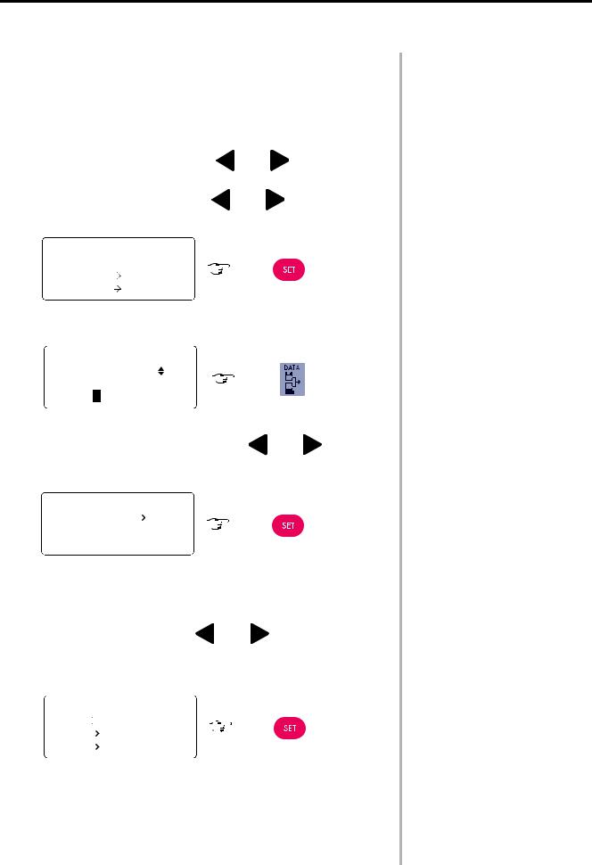
FUNCTION MENU
CHANGING DISPLAY - - - - - - - - - - - - - - - - - - - - - - - - 33 THREAD BREAK SENSOR - - - - - - - - - - - - - - - - - - - - 34 BOBBIN COUNTER (SET) - - - - - - - - - - - - - - - - - - - - - 35 BOBBIN COUNTER (COUNTER) - - - - - - - - - - - - - - - - 36 LOCK STITCH - - - - - - - - - - - - - - - - - - - - - - - - - - - - - 37 SATIN ADJUSTMENT - - - - - - - - - - - - - - - - - - - - - - - - 38 SLOW START - - - - - - - - - - - - - - - - - - - - - - - - - - - - - 39 TRIMMING IN JUMP - - - - - - - - - - - - - - - - - - - - - - - - - 40 JUMP LENGTH - - - - - - - - - - - - - - - - - - - - - - - - - - - - - 41 TRIMMING LENGTH - - - - - - - - - - - - - - - - - - - - - - - - - 42 TRIMMING TIMING - - - - - - - - - - - - - - - - - - - - - - - - - - 43 BORING - - - - - - - - - - - - - - - - - - - - - - - - - - - - - - - - - - 44 CORDING - - - - - - - - - - - - - - - - - - - - - - - - - - - - - - - - 45
HOOP MENU
HOOP MODE - - - - - - - - - - - - - - - - - - - - - - - - - - - - - - 46 INITIALIZATION - - - - - - - - - - - - - - - - - - - - - - - - - - - - 47 START POINT RETURN MODE - - - - - - - - - - - - - - - - - 48 MANUAL SPEED - - - - - - - - - - - - - - - - - - - - - - - - - - - 49 HOOP TIMING - - - - - - - - - - - - - - - - - - - - - - - - - - - - - 50 OFFSET - - - - - - - - - - - - - - - - - - - - - - - - - - - - - - - - - - 51 TRACE MODE - - - - - - - - - - - - - - - - - - - - - - - - - - - - - 52
EDIT
SIZE - - - - - - - - - - - - - - - - - - - - - - - - - - - - - - - - - - - - 53 DESIGN ROTATION - - - - - - - - - - - - - - - - - - - - - - - - - 54 MIRROR - - - - - - - - - - - - - - - - - - - - - - - - - - - - - - - - - 55 DESIGN REPEAT - - - - - - - - - - - - - - - - - - - - - - - - - - - 56
COLOR CHANGE SETTING
COLOR CHANGE MODE - - - - - - - - - - - - - - - - - - - - - - 59 NEEDLE BAR SETTING (INPUT) - - - - - - - - - - - - - - - - 60 NEEDLE BAR SETTING (CHANGE) - - - - - - - - - - - - - - 61 PAUSE SETTING - - - - - - - - - - - - - - - - - - - - - - - - - - - 62
DATA SET MENU
DATA INPUT (FLOPPY DISK) - - - - - - - - - - - - - - - - - - 63 DATA INPUT (PC) - - - - - - - - - - - - - - - - - - - - - - - - - - - 65 DATA INPUT (LAN) - - - - - - - - - - - - - - - - - - - - - - - - - - 67 DATA SELECT - - - - - - - - - - - - - - - - - - - - - - - - - - - - - 69 DATA DELETION - - - - - - - - - - - - - - - - - - - - - - - - - - - 70 MEMORY MODE - - - - - - - - - - - - - - - - - - - - - - - - - - - - 71 MEMORY INITIALIZATION - - - - - - - - - - - - - - - - - - - - 72
MANUAL OPERATION
COLOR CHANGE - - - - - - - - - - - - - - - - - - - - - - - - - - - 73 START POINT RETURN MODE - - - - - - - - - - - - - - - - - 74 TRACE - - - - - - - - - - - - - - - - - - - - - - - - - - - - - - - - - - - 75 OFFSET (POSITION SETTING) - - - - - - - - - - - - - - - - - 76 OFFSET (HOOP TRAVELING) - - - - - - - - - - - - - - - - - - 77 TRIMMING - - - - - - - - - - - - - - - - - - - - - - - - - - - - - - - - 78 HOOP FORWARD/BACK (TRAVEL UNITS) - - - - - - - - 79 HOOP FORWARD/BACK (n-STITCH FEED) - - - - - - - - 80 HOOP FORWARD - - - - - - - - - - - - - - - - - - - - - - - - - - - 81 HOOP BACK - - - - - - - - - - - - - - - - - - - - - - - - - - - - - - - 82
OUTLINE OF FUNCTIONS |
|
ROTATION - - - - - - - - - - - - - - - - - - - - - - - - - - - - - - - - |
83 |
MIRROR - - - - - - - - - - - - - - - - - - - - - - - - - - - - - - - - - - - |
83 |
REPEAT - - - - - - - - - - - - - - - - - - - - - - - - - - - - - - - - - - |
84 |
OFFSET - - - - - - - - - - - - - - - - - - - - - - - - - - - - - - - - - - |
85 |
SATIN ADJUSTMENT - - - - - - - - - - - - - - - - - - - - - - - - |
87 |
TRACE - - - - - - - - - - - - - - - - - - - - - - - - - - - - - - - - - - - - |
88 |
SAFETY |
PRECAUTIONS |
|
|
PART |
NAMES |
|
|
|
|
PREPARATION |
|
|
|
OPERATION |
PROCEDURE |
|
|
TROUBLESHOOTING AND MAINTENANCE - - - - - - - - - - - - - - - - - - - - - - - - - - - - - 89
DAILY MAINTENANCE - - - - - - - - - - - - - - - - - - - - - - - - - - - - - - - - - - - - - - - - - - - - - - - - - - - - - - - - - - - - - - - - - - - - - - - - - - - - - 89
PROGRAM INSTALLATION - - - - - - - - - - - - - - - - - - - - - - - - - - - - - - - - - - - - - - - - - - - - - - - - - - - - - - - - - - - - - - - - - - - - - -93
TEST MODE
NETWORK SETTING - - - - - - - - - - - - - - - - - - - - - - - - - - - - - - - - - - - - - - - - - - - - - - - - - - - - - - - - - - - - - - - - - - - - - - - - - - -95 LANGUAGE - - - - - - - - - - - - - - - - - - - - - - - - - - - - - - - - - - - - - - - - - - - - - - - - - - - - - - - - - - - - - - - - - - - - - - - - - - - - - - - - - -97 IF MACHINE OPERATION IS INTERRUPTED - - - - - - - - - - - - - - - - - - - - - - - - - - - - - - - - - - - - - - - - - - - - - - - - - - - - - - - - -98 IF MACHINE STOPS DUE TO OCCURRENCE OF A TROUBLE - - - - - - - - - - - - - - - - - - - - - - - - - - - - - - - - - - - - - - - - - - - 101
TROUBLESHOOTING |
AND MAINTENANCE |
|
|
SPECIFICATION |
|
|
|
SPECIFICATION - - - - - - - - - - - - - - - - - - - - - - - - - - - - - - - - - - - - - - - - - - - - - - - - -102
INDEX - - - - - - - - - - - - - - - - - - - - - - - - - - - - - - - - - - - - - - - - - - - - - - - - - - - - - - - - -103
From the library of Superior Sewing Machine & Supply LLC - www.supsew.com
INDEX
SAFETY |
PRECAUTIONS |
|
|
II
 SAFETY PRECAUTIONS (Make sure to read the following before use)
Safety precautions are provided to prevent risks and losses which could result from incorrect handling.
Please read carefully and comply strictly with them.
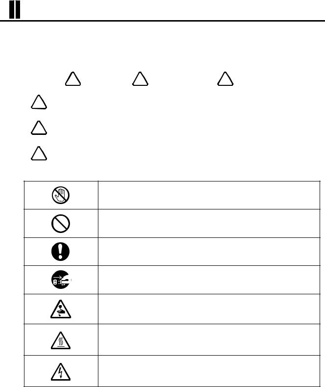
Meaning of " ! DANGER", " ! WARNING" and " ! CAUTION"
6! |
DANGER |
Indicates there could be imminent risk of situation resulting in fatal or serious injury |
from incorrect handling. |
||
6! |
WARNING |
Indicates there could be possible accident of fatal or serious injury resulting from |
incorrect handling. |
||
6! |
CAUTION |
Indicates incorrect handling could cause physical injury or damage on goods. |
|
Meaning of Pictographs
Prohibition of touching
Prohibited action
Mandatory action
Disconnection of the power cord plug from receptacle
Caution on finger injury
Caution on high temperature
Caution on electric shock
2
From the library of Superior Sewing Machine & Supply LLC - www.supsew.com
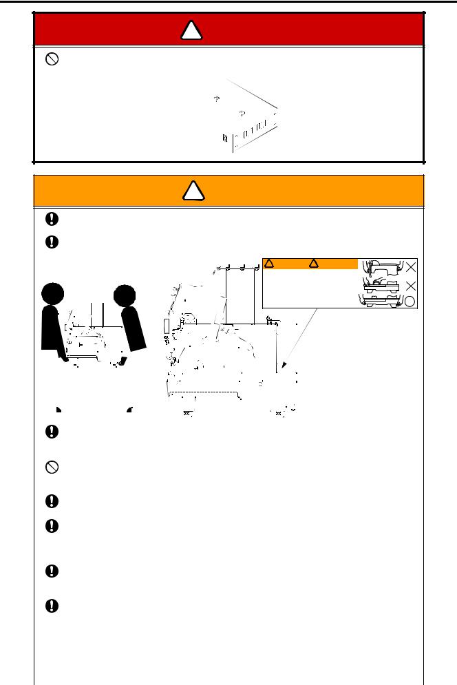
! DANGER
Do not open the power supply box.
Otherwise, you may sustain electric shock.
|
! WARNING |
|
|
||
0 |
Carry the machine by two or more persons. |
|
|
|
|
0 |
Falling the machine may cause injury as well as breakdown of the machine. |
|
|||
When carrying the machine, hold the machine at the positions specified by the label. |
|||||
|
Falling the machine may cause injury as well as breakdown of the machine. |
|
|||
|
~ |
|
! WARNING |
! ATTENTION |
~xX |
|
- |
CARRYING |
|
||
|
11 f!,...L_-----'~ |
||||
|
|
Carry the machine with |
Il faut être au moins 2personnes |
||
|
|
|
at least two people. |
pour porter la machine. |
|
|
|
|
DO NOT hold it by parts |
Ne pas tenir la machine par |
|
|
|
|
other than those specified. |
une autre partie que celle |
'~o |
|
|
|
Dropping may cause bodily |
indiquées. |
|
|
|
|
injury and will damage |
Une chute peut vous blesser |
|
|
|
|
the machine. |
et endommager la machine. |
|
|
|
|
|
|
|
|
|
|
|
|
|
|
|
|
|
|
|
|
|
|
|
|
|
|
|
|
|
|
|
|
|
|
|
|
|
|
|
|
|
|
|
|
|
|
|
|
|
|
|
|
|
|
|
|
|
|
|
|
|
|
|
|
|
|
|
|
|
|
|
|
|
|
|
|
|
|
|
|
|
|
|
|
|
|
|
|
|
|
|
|
|
|
|
|
|
|
|
|
|
|
|
|
|
|
|
|
|
|
|
|
|
|
|
|
|
|
|
|
|
|
|
|
|
|
|
|
|
|
|
|
|
|
|
|
|
|
|
|
|
|
|
|
|
|
|
|
|
|
|
|
|
|
|
|
|
|
|
|
|
|
|
|
|
|
|
|
|
|
|
|
|
|
|
|
|
|
|
|
|
|
|
|
|
|
|
|
|
|
|
|
|
|
|
|
|
|
|
|
|
|
|
|
|
|
|
|
|
|
|
|
|
|
|
|
|
|
|
|
|
|
|
|
|
|
|
|
|
|
|
|
|
|
|
|
|
|
|
|
|
|
|
|
|
|
|
|
|
|
|
|
|
|
|
|
|
|
|
|
|
|
|
|
|
|
|
|
|
|
|
|
|
|
|
|
|
|
|
|
|
|
|
|
|
|
|
|
|
|
|
|
|
|
|
|
|
|
|
|
|
|
|
|
|
|
|
|
|
|
|
|
|
|
|
|
|
|
|
|
|
|
|
|
|
|
|
|
|
|
|
|
|
|
|
|
|
|
|
|
|
|
|
|
|
|
|
|
|
|
|
|
|
|
|
|
|
|
|
|
|
|
|
|
|
|
|
|
|
|
|
|
|
|
|
|
|
|
|
|
|
|
|
|
|
|
|
|
|
|
|
|
|
|
|
|
|
|
|
|
|
|
|
|
|
|
|
|
|
|
|
|
|
|
|
|
|
|
|
|
|
|
|
|
|
|
|
|
|
|
|
|
|
|
|
|
|
|
|
|
|
|
|
|
|
|
|
|
|
|
|
|
|
|
|
|
|
|
|
|
|
|
|
|
|
|
|
|
|
|
|
|
|
|
|
|
|
|
|
|
|
|
|
|
|
|
|
|
|
|
|
|
|
|
|
|
|
|
|
|
|
|
|
|
|
|
|
|
|
|
|
|
|
|
|
|
|
|
|
|
|
|
|
|
|
|
|
|
|
|
|
|
|
|
|
|
|
|
|
|
|
|
|
|
|
|
|
|
|
|
|
|
|
|
|
|
|
|
|
|
|
|
|
|
|
|
|
|
|
|
|
|
|
|
|
|
|
|
|
|
|
|
|
|
|
|
|
|
|
|
|
|
|
|
|
|
|
|
|
|
|
|
|
|
|
|
|
|
|
|
|
|
|
|
|
|
|
|
|
|
|
|
|
|
|
|
|
|
|
|
|
|
|
|
|
|
|
|
|
|
|
|
|
|
|
|
|
|
|
|
|
|
|
When installing the machine, make sure to place it on the attached vibration-preventive rubbers |
||||||||||||||||||||||||||||||||||||||||||||||||||||||||||||||
|
|
(H). |
||||||||||||||||||||||||||||||||||||||||||||||||||||||||||||||
|
|
Falling the machine may cause injury as well as breakdown of the machine. |
||||||||||||||||||||||||||||||||||||||||||||||||||||||||||||||
0 |
Do not damage, modify, heat or apply undue force to the power cords and other connection |
|||||||||||||||||||||||||||||||||||||||||||||||||||||||||||||||
|
|
cables. |
||||||||||||||||||||||||||||||||||||||||||||||||||||||||||||||
0 |
Otherwise the cables may be damaged causing fire and electric shock. |
|||||||||||||||||||||||||||||||||||||||||||||||||||||||||||||||
Insert the power cord plug fully. |
||||||||||||||||||||||||||||||||||||||||||||||||||||||||||||||||
0 |
Incomplete insertion could cause fire or electric shock. |
|||||||||||||||||||||||||||||||||||||||||||||||||||||||||||||||
Keep away electric and electronic units from water and oils. |
||||||||||||||||||||||||||||||||||||||||||||||||||||||||||||||||
|
|
Exposure them to water or oils leads to short circuits, causing fire and electric shock. |
||||||||||||||||||||||||||||||||||||||||||||||||||||||||||||||
|
|
If water or oils enter the electric/electronic units, shut off the power by the power switch, shut off |
||||||||||||||||||||||||||||||||||||||||||||||||||||||||||||||
0 |
the source of power supply and contact your TOYOTA dealer. |
|||||||||||||||||||||||||||||||||||||||||||||||||||||||||||||||
When disconnecting the power cord from the receptacle, pull the cord while holding the plug. |
||||||||||||||||||||||||||||||||||||||||||||||||||||||||||||||||
|
|
Pulling the power cord by holding the cord may damage the cord and the plug, causing fire and |
||||||||||||||||||||||||||||||||||||||||||||||||||||||||||||||
|
|
electric shock. |
||||||||||||||||||||||||||||||||||||||||||||||||||||||||||||||
|
|
The machine must be switched off at the mains switch on the power supply or by unplugging it |
||||||||||||||||||||||||||||||||||||||||||||||||||||||||||||||
|
|
from the incoming mains supply, when: |
||||||||||||||||||||||||||||||||||||||||||||||||||||||||||||||
|
|
• |
|
Sewing implements (thread, needle, bobbin, etc.) have to be replaced or adjusted |
||||||||||||||||||||||||||||||||||||||||||||||||||||||||||||
|
|
• |
|
Threading a needle, bobbin, etc |
||||||||||||||||||||||||||||||||||||||||||||||||||||||||||||
|
|
• |
|
If the workplace is left unattended |
||||||||||||||||||||||||||||||||||||||||||||||||||||||||||||
|
|
• |
|
Maintenance work has to be performed |
||||||||||||||||||||||||||||||||||||||||||||||||||||||||||||
|
|
|
|
|
|
|
|
|
|
|
|
|
|
|
|
|
|
|
|
|
|
|
|
|
|
|
|
|
|
|
|
|
|
|
|
|
|
|
|
|
|
|
|
|
|
|
|
|
|
|
|
|
|
|
|
|
|
|
|
|
|
|
|
|
|
|
|
|
|
|
|
|
3 |
|
|
|
|
|
|
|
|
|
|
|
|
|
|
|
|
|
|||||||||||||||||||||||||||||||||||||||
SAFETY |
PRECAUTIONS |
|
|
From the library of Superior Sewing Machine & Supply LLC - www.supsew.com
SAFETY |
PRECAUTIONS |
|
|
|
|
|
|
|
|
|
|
|
|
! CAUTION |
|||||||
|
|
|
|
|
|
|
|
|
|
|
|
|
|
|
|
|
|
|
Do not use the machine in areas where strong electric field or magnetic field is generated by a |
||||||||||||||||
|
high-power high-frequency motor generator or high-frequency welder. |
||||||||||||||||
0 |
Otherwise the machine will malfunction to cause injury or machine trouble. |
||||||||||||||||
Place the machine on a sturdy base. |
|||||||||||||||||
0 |
Otherwise the machine may fall to cause injury or machine trouble. |
||||||||||||||||
Ground the grounding wire of the power cord. |
|||||||||||||||||
|
There is the danger of electric shock due to leak current if the machine is used without |
||||||||||||||||
|
grounding. |
|
|
|
|
|
|
|
|
|
|
|
|
||||
|
Do not touch the parts ( |
|
|
|
) of the machine that move during embroidery. |
||||||||||||
|
|
|
|||||||||||||||
|
Otherwise you will sustain injury. |
||||||||||||||||
|
|
|
|
|
|
|
|
|
|
|
|
|
|
|
|
|
|
|
|
|
|
|
|
|
|
|
|
|
|
|
|
|
|
|
|
|
|
|
|
|
|
|
|
|
|
|
|
|
|
|
|
|
|
|
|
|
|
|
|
|
|
|
|
|
|
|
|
|
|
|
|
|
|
|
|
|
|
|
|
|
|
|
|
|
|
|
|
|
|
|
|
|
|
|
|
|
|
|
|
|
|
|
|
|
|
|
|
|
|
|
|
|
|
|
|
|
|
|
|
|
|
|
|
|
|
|
|
|
|
|
|
|
|
|
|
|
|
|
|
|
|
|
|
|
|
|
|
|
|
|
|
|
|
|
|
|
|
|
|
|
|
|
|
|
|
|
|
|
|
|
|
|
|
|
|
|
|
|
|
|
|
|
|
|
|
|
|
|
|
|
|
|
|
|
|
|
|
|
|
|
|
|
|
|
|
|
|
|
|
|
|
|
|
|
|
|
|
|
|
|
|
|
|
|
|
|
|
|
|
|
|
|
|
|
|
|
|
|
|
|
|
|
|
|
|
|
|
|
|
|
|
|
|
|
|
|
|
|
|
|
|
|
|
|
|
|
|
|
|
|
|
|
|
|
|
|
|
|
|
|
|
|
|
|
|
|
|
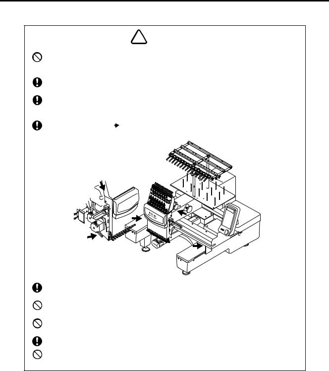
0 |
Take care to attire properly for operations of the embroidery machine. |
0 |
You could get hurt if you wear clothes likely being arrested by the embroidery machine. |
Do not step on the embroidery machine. |
|
|
Otherwise you will sustain injury. |
0 |
Do not operate the machine without the take-up lever guard or the covers of the moving parts. |
|
Otherwise you will sustain injury. |
0 Locate the power supply box to turn the power ON and OFF easily. |
|
0 |
Do not operate the machine with the rotary hook cover opened. |
|
Otherwise you will sustain injury. |
4
From the library of Superior Sewing Machine & Supply LLC - www.supsew.com

Positions and Contents of the Warning Labels
|
|
|
|
|
|
For abnormal conditions. |
|
|
! |
CAUTION |
! |
CAUTION |
Immediately press the eme- |
|
|
|
rgency suspension switch to |
|
|||||
|
ATTENTION |
|
MACHINE |
stop the embroidering machine. |
|
||
|
|
|
En cas de conditions anormales, |
|
|||
Fingers might be injured. |
! |
ATTENTION |
pousser immédiatement sur |
|
|||
Do not put your hand on hoop while in motion. |
le bouton d’arrêt d’urgence pour |
|
|||||
Do not put your finger or hand inside thread |
|
|
stopper la brodeuse. |
|
|||
tension cover or guard cover. |
|
|
|
|
|||
Les doigts peuvent être blessés. |
|
|
|
|
|||
Ne pas mettre la main sur le cercle à broder quand il |
|
|
|
|
|||
est en mouvement. |
|
|
|
|
|
||
Ne pas mettre les doigts ou la main dans le couvercle |
|
|
|
|
|||
du système de tension ou le couvercle de protection. |
|
|
! WARNING |
! ATTENTION |
|||
|
|
|
|
|
|
||
|
|
|
|
|
|
CARRYING |
|
|
|
|
|
|
|
Carry the machine with |
Il faut être au moins 2personnes |
|
|
|
|
|
|
at least two people. |
pour porter la machine. |
|
|
|
|
|
|
DO NOT hold it by parts |
Ne pas tenir la machine par |
|
|
|
Cover must be closed |
|
|
other than those specified. |
une autre partie que celle |
! |
CAUTION |
|
|
Dropping may cause bodily |
indiquées. |
||
during operation. |
|
|
the machine. |
et endommager la machine. |
|||
|
|
|
|
|
|
injury and will damage |
Une chute peut vous blesser |
! |
ATTENTION |
Le couvercle doit être |
|
|
|
|
|
fermé durant l’utilisation. |
|
|
|
|
|||
! |
CAUTION |
|
|
|
|
|
|
|
|
|
|
|
|
|
|
|
|
|
|
ATTENTION |
|
|
|
|
|
|
|
|
|
|
|
|
|
|
|
|
|
||
|
|
|
|
|
|
|
|
|
|
|
|
|
! |
CAUTION |
|
||||
Do not operate without finger guard and |
|
|
|
|
|
|
|
|
|
|
|
|
|
|
|||||
safety devices. Before threading, changing |
|
|
|
|
|
|
|
|
|
|
|
|
|
ATTENTION |
|
||||
bobbin and needle, cleaning etc. Switch |
|
! |
CAUTION |
|
Fingers might be injured. |
|
|
||||||||||||
off main switch. |
|
|
|
|
|||||||||||||||
Ne pas travailler sans protection aux |
|
ATTENTION |
|
Do not put your hand on hoop while in motion. |
|
||||||||||||||
|
|
Do not put your finger or hand inside thread |
|
||||||||||||||||
doigts et aux mains et sans dispositif |
|
Fingers might be injured. |
|
tension cover or guard cover. |
|
|
|||||||||||||
de sécurité. Avant d’enfiler, changer de |
|
Do not put your hand on hoop while in motion. |
|
Les doigts peuvent être blessés. |
|
|
|||||||||||||
canette ou d’aiguilles, nettoyer. Eteindre |
|
Do not put your finger or hand inside thread |
|
|
|
||||||||||||||
|
|
Ne pas mettre la main sur le cercle à broder quand il |
|
||||||||||||||||
la machine. |
|
|
|
tension cover or guard cover. |
|
|
|||||||||||||
|
|
|
|
est en mouvement. |
|
|
|||||||||||||
|
|
|
|
|
|
|
|
|
|
|
|
|
|
|
|
|
|
||
|
|
|
|
Les doigts peuvent être blessés. |
|
Ne pas mettre les doigts ou la main dans le couvercle |
|
||||||||||||
|
|
|
|
Ne pas mettre la main sur le cercle à broder quand il |
|
du système de tension ou le couvercle de protection. |
|
||||||||||||
|
|
|
|
est en mouvement. |
|
|
|
|
|
||||||||||
|
|
|
|
Ne pas mettre les doigts ou la main dans le couvercle |
|
|
! |
CAUTION |
|||||||||||
|
|
|
|
du système de tension ou le couvercle de protection. |
|
|
|||||||||||||
|
|
|
|
|
|
|
|
|
|
|
|
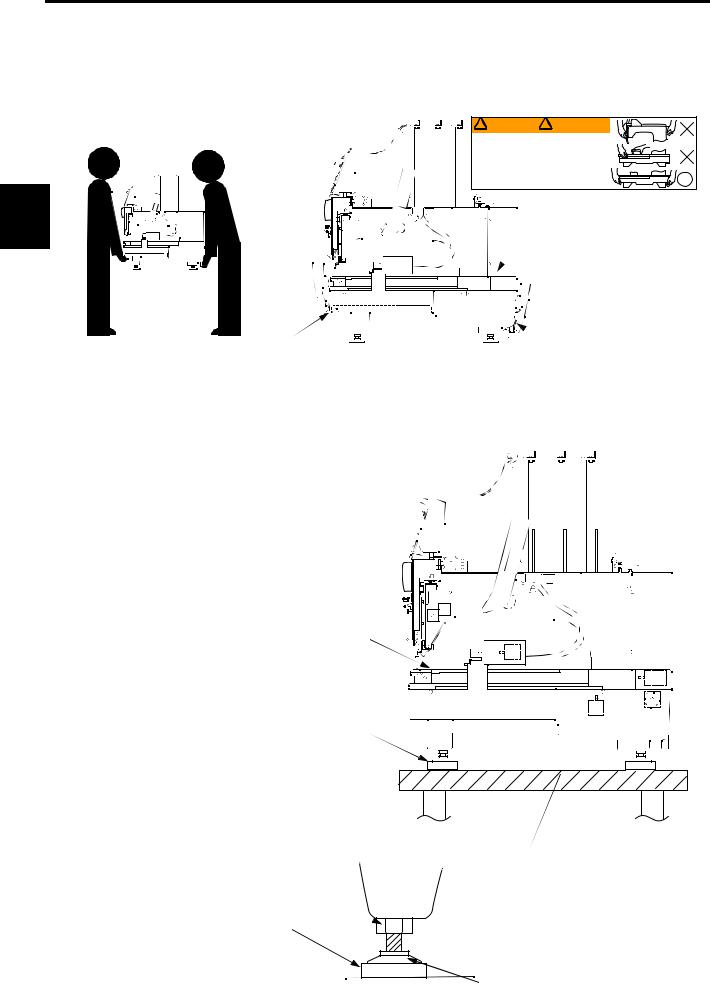
|
|
|
|
|
ATTENTION |
||
|
|
|
|
|
|
|
|
|
|
|
|
|
|
|
|
|
|||
|
|
|
|
|
|
|
|
|
|
|
|
|
|
|
|
|
Fingers might be injured. |
||
|
|
|
|
|
|
|
|
|
|
|
|
|
|
|
|
|
Do not put your hand on hoop while in motion. |
||
|
|
It. |
|
Riskof |
Risque dechoc |
|
|
Do not put your finger or hand inside thread |
|||||||||||
|
|
|
eI |
ectr ic shock |
|
|
electrique. |
|
tension cover or guard cover. |
||||||||||
|
|
|
|
||||||||||||||||
|
|
|
Don'topen |
Ne pas ouvrir |
|
Les doigts peuvent être blessés. |
|||||||||||||
|
|
|
|
this cover. |
ce couvercle. |
|
|
|
|
Ne pas mettre la main sur le cercle à broder quand il |
|||||||||
|
|
|
|
|
|
|
|
|
|
|
|
|
|
|
|
|
est en mouvement. |
||
|
|
|
|
|
Lt.CAUTION |
|
|
,t. ATTENTION |
|
|
|
||||||||
|
|
|
|
|
|
|
|
|
|
|
|
|
|
|
|
|
Ne pas mettre les doigts ou la main dans le couvercle |
||
|
|
|
This switch should |
be within L'interrupteur do,i~ etrefacile |
|
|
|
du système de tension ou le couvercle de protection. |
|||||||||||
|
|
|
|
|
|
||||||||||||||
easy reach of the operator. d'acces pour l'ut1l1sateur
! CAUTION
 ATTENTION
While the machine is running, keep this cover closed.
Pendant que la machine tourne, gandez le couvercle fermé.
SAFETY |
PRECAUTIONS |
|
|
!CAUTION
ATTENTION
Fingers might be injured.
Do not put your hand on hoop while in motion. Do not put your finger or hand inside thread tension cover or guard cover.
Les doigts peuvent être blessés.
Ne pas mettre la main sur le cercle à broder quand il est en mouvement.
Ne pas mettre les doigts ou la main dans le couvercle du système de tension ou le couvercle de protection.
5
!CAUTION
ATTENTION
Fingers might be injured.
Do not put your hand on hoop while in motion.  Do not put your finger or hand inside thread
tension cover or guard cover.
Les doigts peuvent être blessés.
Ne pas mettre la main sur le cercle à broder quand il est en mouvement.
Ne pas mettre les doigts ou la main dans le couvercle du système de tension ou le couvercle de protection.
From the library of Superior Sewing Machine & Supply LLC - www.supsew.com
II
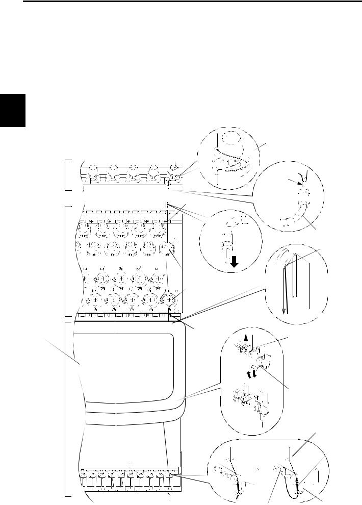
 PART NAMES
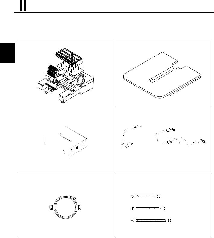
CHECKING THE PARTS
After unpacking the machine, check to be sure that all of the items below have been delivered.
● Embroidery machine (1 set) |
● Table (1 pc.) |
NAMES
PART
● Power supply box (1 pc.) |
● Power cord |
|
|
AC power cord (1 pc.) |
DC power cord (1 pc.) |
* An additional AC power cord and plug for 250 V are included only for USA/Canada spec.
● Embroidery hoop (2 pcs.) |
● Spiral tube |
|
|
<Tubular frame> |
|
|
|
|
Small - - - - - - - - - - |
(5 |
pcs.) |
|
Medium - - - - - - - - - - |
(4 pcs.) |
|
|
Large - - - - - - - - - - |
(6 |
pcs.) |
6
From the library of Superior Sewing Machine & Supply LLC - www.supsew.com
ACCESSORIES |
|
|
|
● Instruction manual |
● Parts catalogue |
● Vibration-preventive |
* We reserve the right to |
(1 copy) |
(1 copy) |
rubber (H) |
change the contents of this |
(This book) |
|
|
instruction manual without |
|
|
|
prior notice. |
|
|
DD |
PART NAMES |
INSTRUCTION |
PARTS |
|
|
MANUAL |
CATALOGUE |
|
|
|
|
DD |
|
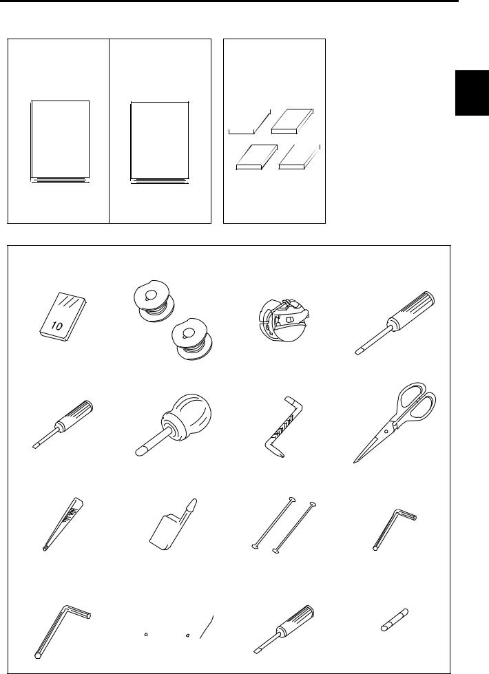
● Tools
(1) Needle (#11) 10 pcs. |
(2) Aluminum bobbin 2 pcs. |
(3) Bobbin case 1 pc. |
(4) Minus screwdriver (large) |
|
|
|
1 pc. |
(5) Minus screwdriver (small) |
(6) Offset screwdriver |
(7) L-shaped screwdriver |
(8) Scissors 1 pc. |
1 pc. |
1 pc. |
(plus/minus) 1 pc. |
|
(9) Small pincers 1 pc. |
(10) Oiler 1 pc. |
(11) Threader 2 pcs. |
(12) L wrench (3 mm) |
1 pc.
d //
(13) Allen wrench (4 mm) |
(14) Tool bag 1 pc. |
(15)Hexagonal wrench (3 mm) |
(15)Fuse 1 pc. |
|
1 pc. |
|
|
1 pc. |
|
|
|
|
|
|
|
|
|
|
|
|
|
|
|
|
7
From the library of Superior Sewing Machine & Supply LLC - www.supsew.com
PART NAMES
EMBROIDERY MACHINE
Thread guide |
|
|
|
||||||||||||||||||||||||||||||||||
Sub thread tension regulator |
|
|
|
||||||||||||||||||||||||||||||||||
|
|
|
|
|
|
|
|
|
|
|
|
|
|
|
|
|
|
|
|
|
|
|
|
|
|
|
|
|
|
|
|
|
|
|
|
|
Tension base cover |
|
|
|
|
|
|
|
|
|
|
|
|
|
|
|
|
|
|
|
|
|
|
|
|
|
|
|
|
|
|
|
|
|
|
|
|
|
|
|
Spiral tube |
|
|
|
|
|
|
|
|
|
|
|
|||||||||||||||||||||||||
Thread tension regulator |
|
|
|
|
|
|
|
|
|
|
Thread stand shaft |
||||||||||||||||||||||||||
Tension base |
|
|
|
|
|
|
|
|
|
|
|
||||||||||||||||||||||||||
Operation panel box |
|
|
|
|
|
|
|
|
|
|
Thread stand stud |
||||||||||||||||||||||||||
(For details, refer to Page 9.) |
|
|
|
|
|
|
|
|
|
|
|||||||||||||||||||||||||||
|
|
|
|
|
|
|
|
|
|
|
|||||||||||||||||||||||||||
Color change motor |
|
|
|
|
|
|
|
|
|
|
Under thread winder |
||||||||||||||||||||||||||
Take-up lever |
|
|
|
|
|
|
|
|
|
|
|
|
|
|
|
|
|
|
|
|
|
|
|
|
|||||||||||||
Thread take-up cover |
|
|
|
|
|
|
|
|
|
|
|
|
|
|
|
|
|
|
|||||||||||||||||||
Thread hook motor |
|
|
|
|
|
|
|
|
|
|
|
|
|
|
|
|
|
|
|
|
|
||||||||||||||||
|
|
|
|
|
|
|
|
|
|
|
|
|
|
|
|
|
|
|
|
|
|
|
|
|
|
||||||||||||
Jump motor |
|
|
|
|
|
|
|
|
|
|
|
|
|
|
|
|
|
|
|
|
|
|
|
|
|
||||||||||||
|
|
|
|
||||||||||||||||||||||||||||||||||
|
|
|
|
|
|
|
|
|
|
|
|
|
|
|
|
|
|
|
|
|
|
|
|
|
|||||||||||||
Needle bar case |
|
|
|
|
|
|
|
|
|
|
|
|
|
|
|
|
|||||||||||||||||||||
|
|
|
|
|
|
|
|
|
|
|
|
|
|
|
|
|
|
|
|
|
|
|
|
|
|
|
|
|
|
|
|
|
|
|
|
||
|
|
|
|
|
|
|
|
|
|
|
|
|
|
|
|
||||||||||||||||||||||
|
|
|
|
|
|
|
|
|
|
|
|
|
|||||||||||||||||||||||||
|
|
|
|
|
|
|
|
|
|
|
|
|
|
|
|
|
|
|
|
|
|
|
|
|
|
|
|
|
|
|
|
|
|||||
X/Y-axis drive system |
|
|
Needle plate |
X-axis drive motor |
|
Table |
Main shaft motor |
|
Base |
Y-axis drive motor |
|
Thread trimming motor |
||
|


 Drain port
Adjuster foot
USB connector |
LAN connector |
Serial connector |
Power supply |
connector |
8
From the library of Superior Sewing Machine & Supply LLC - www.supsew.com
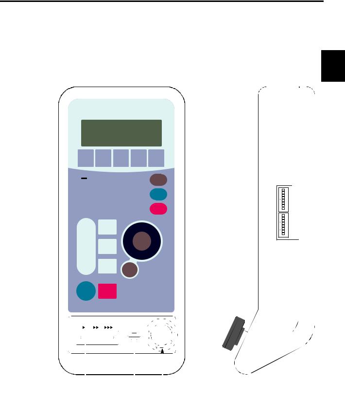
OPERATION PANEL BOX
Function menu key
Hoop menu key
Edit key
Color change key
Data set menu key
---- \
|
|
|
TOYOTA |
•- |
|
I |
LCD screen |
|
|
|
|
|
|
|
|
|
|
|
|
||
|
|
|
|
|
|
|
DIP switches |
|
|
|
|
|
|
|
|
|
|
(For details, refer to |
|
|
|
|
|
|
., DATA [Z][ID[ID[D] |
|
|
|
Page 10.) |
|
|
|
Ten keys |
LED |
I |
|
|
|
Escape key |
|
|
||
|
|
|
|
|
|
|
||||
(numeric keys) |
|
.. |
|
|
|
[I] |
|
|||
(~ |
|
~= -..@[ID[§] |
|
|
Clear key |
[I] |
7 8 |
|||
:Used for a |
|
|
|
4 |
~ |
|
[I] |
21ON3 4 5 6 |
||
needle bar number |
) |
[I)[2]raJ00 |
|
|
|
[I] |
||||
of 10 or larger |
~4 |
|
[I] |
|||||||
Set key |
[I] |
|||||||||
|
|
|
|
|
|
|
|
|||
|
|
|
|
|
|
|
|
[I] |
|
|
Trace key |
|
|
|
|
|
|
|
7 |
||
|
|
|
|
|
|
|
|
|
8 |
|
|
|
|
|
|
|
|
Hoop travel key |
|
6 |
|
Hoop forward key |
|
|
|
|
|
|
3 4 5 |
|||
Offset key |
|
|
|
|
|
|
|
ON1 2 |
||
Forward/Back |
|
|
|
|
|
Start point return key |
r |
|||
unit selection key |
|
|
|
|
|
|
|
|
||
Thread trimming
key 


 Hoop back key


Stop key  Start key
|
|
SLOW ► ►► |
►►►FAST |
 Color change mode (automatic/manual) key
Manual lamp |
|
Lights when manual |
|
(selected.color change is |
) |
Needle bar case |
|
right-slide key |
|
Needle bar case |
|
left-slide key |
|
|
|
|
|
MACHINE |
|
STOP |
|
|
SPEED |
|
|
|
|||||
|
|
|
||||||
|
|
|
|
|
||||
|
|
|
|
|
|
|
|
|
|
|
|
|
|
|
|
|
|
Speed adjusting switch |
Buzzer Machine stop switch |
PART NAMES
9
From the library of Superior Sewing Machine & Supply LLC - www.supsew.com
PART NAMES
DIP SWITCHES
DIP switch ON or OFF is set as follows:
|
|
|
|
|
|
|
|
DSW 2 |
|
|
|
|
|
|
|
|
|
|
|
|
|
|
|
|
|
|
|
|
|
|
|
|
|
|
No. |
Function |
OFF |
ON |
|
|
|
|
|
|
|
|
|
|
|
|
|
|
|
|
|
|
|
|
|
|
|
|
|
|
|
|
|
|
|
|
|
8 |
PC connection |
* Two-way communica- |
Older mode |
||
|
|
|
|
|
|
|
tions (Standard) |
|||||
|
|
|
|
|
|
|
|
|
|
|
|
|
|
|
|
|
|
|
|
|
|
|
|
|
|
|
|
|
|
|
|
|
7 |
PC connection |
* Normal operation |
Synchronous operation |
||
|
|
|
|
|
|
|
|
|
|
|
|
|
|
|
|
|
|
|
|
6 |
Not used |
*Select OFF. |
− |
||
|
|
|
|
|
|
|
|
|
|
|
|
|
|
|
|
|
|
|
|
5 |
Not used |
*Select OFF. |
− |
||
|
|
|
|
|
|
|
|
|
|
|
|
|
|
|
|
|
|
|
|
|
|
|
Satin stitch width |
*Adjustment for stitch |
Adjustment for stitch |
|
|
|
|
|
|
|
|
4 |
width of 1.5 mm or |
|||
|
|
|
|
|
|
|
|
adjustment |
width of 0.6 mm or larger |
|||
|
|
|
|
|
|
|
|
|
|
larger |
||
|
|
|
1■• |
8 |
|
|
|
|
|
|
|
|
|
|
|
|
|
7 |
|
|
|
|
Satin stitch adjust- |
|
|
|
|
|
l■ |
- |
6 |
|
3 |
ment mode selec- |
*Collective adjustment |
Independent adjust- |
||
|
|
|
1■ |
- |
|
for X- and Y-axis |
ment for X- and Y-axis |
|||||
|
|
|
5 |
|
|
|
|
tion |
||||
DSW2 |
|
|
l■ |
- |
4 |
|
|
|
|
|
|
|
|
|
|
|
|
|
|
|
|
||||
|
|
|
|
|
|
|||||||
|
|
|
1■ |
- |
3 |
|
2 |
Not used |
*Select OFF. |
− |
||
|
|
|
1■• |
|
|
|
|
|
|
|
||
|
|
|
1■• |
2 |
|
|
|
|
|
|
|
|
|
|
|
|
1 |
Installation mode |
*Normal mode |
Installation mode if |
|||||
|
|
|
1 |
|
||||||||
|
|
|
I■ |
- |
|
DSW1-1 is ON. |
||||||
|
|
|
ON |
|
|
|
|
|
|
|||
|
|
|
|
|
|
|
|
|
|
|
|
|
|
|
|
|
|
DSW 1 |
|
|
|
||||
|
|
|
1■• |
8 |
|
|
|
|
|
|||
|
|
|
7 |
|
|
|
|
|
||||
|
|
|
l■ |
- |
|
|
|
|
|
|
|
|
|
|
|
|
|
|
No. |
Function |
OFF |
ON |
|||
|
|
|
6 |
|
|
|
||||||
|
|
|
1■ |
- |
|
|
|
|
|
|
|
|
|
|
|
l■ |
- |
5 |
|
|
|
|
|
|
|
|
|
|
|
|
|
|
|
|
|
|||
DSW1 |
|
|
|
8 |
Not used |
*Select OFF. |
High speed |
|||||
|
|
4 |
|
|||||||||
|
|
|
1■ |
- |
|
|
|
|
|
|
|
|
|
|
|
1■• |
3 |
|
7 |
Not used |
*Select OFF. |
− |
|||
|
|
|
1■• |
2 |
|
|
|
|
|
|
|
|
|
|
|
|
|
|
6 |
Cover sensor |
* Invalid |
Valid |
|||
|
|
|
I■ |
- |
1 |
|
||||||
|
|
|
ON |
|
|
|
|
|
|
|
||
|
|
|
~ |
|
|
5 |
Beam sesor |
* Invalid |
Valid |
|||
|
|
|
|
|
|
|
||||||
|
|
|
|
|
|
|
|
|
|
|
|
|
|
|
|
|
|
|
|
|
|
|
|
|
|
|
|
|
|
|
|
|
|
|
|
Hoop travel direc- |
*Same direction as indi- |
Opposite to the direction |
|
|
|
|
|
|
|
4 |
tion: Arrow symbols |
||||
|
|
|
|
|
|
|
cated by the arrow |
indicated by the arrow |
||||
|
|
|
|
|
|
|
and actual travel |
|||||
|
|
|
|
|
|
|
|
|
|
symbol |
symbol |
|
|
|
|
|
|
|
|
|
|
|
direction |
||
|
|
|
|
|
|
|
|
|
|
|
|
|
|
|
|
|
|
|
|
|
|
|
|
|
|
|
|
|
|
|
|
|
3 |
Buzzer sounds |
*10 times |
1 time |
||
|
|
|
|
|
|
|
|
|
|
|
|
|
|
|
|
|
|
|
|
2 |
Not used |
*Select OFF. |
− |
||
|
|
|
|
|
|
|
|
|
|
|
|
|
|
|
|
|
|
|
|
1 |
Test mode |
*Normal operation |
Test mode |
||
|
|
|
|
|
|
|
|
|
|
|
|
|
m After changing the setting of a DIP switch, turn the power switch off once and then turn it back on.
m *: Factory-setting made before shipping
Access to the Embroidery Information
In the test mode, you can access to the following information:
●Accumulated number of embroidered pieces of cloth
●Accumulated number of stitches
●Accumulated number of error displays and others Consult your TOYOTA dealer for more details.
10
From the library of Superior Sewing Machine & Supply LLC - www.supsew.com
II
 PREPARATION
ASSEMBLING
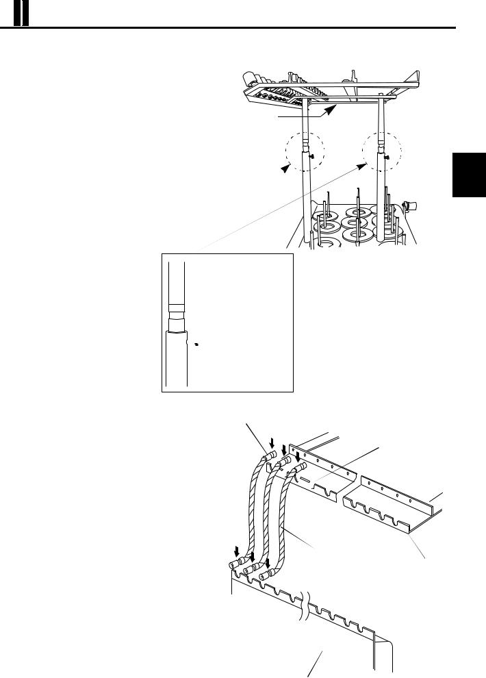
● Preparation of the thread guide
1. Loosen the pair of set screws (3) for thread
stand shaft (1) using an allen wrench and lift
the thread guide (4) right above.
Thread guide (4)
2. Securely tighten the pair of set screws (3) using an allen wrench, at the position where the top of thread stand shafts (1) and the position alignment line (5) of the thread stand shaft (2) is aligned.
PREPARATION
[Enlarged view]
 Thread stand shaft (2)
 Position alignment line (5)

 Set screw (3)
 Thread stand shaft (1)
● Mounting the spiral tubes
1.Place the joint on the one end of spiral tube (large) in the U-shaped slot on the thread guide and fix it in the slot by pressing in the arrow direction. Set and fix the joint on the other end of spiral tube in the U-shaped slot on the tension base in the same way. Repeat the same steps on the U-shaped slots as numbered (1) to
(3) and (13) to (15) in the figure shown at right.
Spiral tube (large): |
No. 1 to No. 30, |
|
No. 13 to No. 15 |
2.In the similar manner, fit the spiral tube B (medium) into the U-shaped slots.
Spiral tube (medium): |
No. 4, No. 5, |
|
No. 11, No. 12 |
3.In the similar manner, fit the spiral tube (small) into the U-shaped slots.
Spiral tube (small): |
No. 6 to No. 10 |
Tube joint
U-shaped slots
(1)

(2)(3)
(4)
(5)
|
|
(12)(13) (14) |
(15) |
|
|
|
|
|
|
Spiral tube (large) |
|
|
|
Tube joint |
Thread guide |
|
|
|
|
(1) |
|
U-shaped slots |
|
(2) |
(3) |
|
|
|
|
(4) |
|
|
|
(5) |
|
|
|
(12)(13) |
|
|
|
(14) (15) |
|
|
|
I |
|
|
|
Tension base |
|
11
From the library of Superior Sewing Machine & Supply LLC - www.supsew.com
CARRYING
As shown in the illustration below, hold the machine at the positions indicated in the label by two or more persons to carry the machine.
! WARNING |
! ATTENTION |
~x |
CARRYING |
|
|
|
~x |
|
Carry the machine with |
Il faut être au moins 2personnes |
|
at least two people. |
pour porter la machine. |
|
DO NOT hold it by parts |
Ne pas tenir la machine par |
|
other than those specified. |
une autre partie que celle |
|
Dropping may cause bodily |
indiquées. |
|
injury and will damage |
Une chute peut vous blesser |
~'O |
the machine. |
et endommager la machine. |
PREPARATION
Machine holding position |
(indicated in the label) |
 Machine holding position (indicated in the label)
INSTALLATION
Place the embroidery machine on a rugged base so that the table will be level.
At this time, make sure to place attached vibration-preventive rubbers (H) under the adjuster foot (1). The rubbers will effectively prevent the machine from moving on the table or vibrating.
If the machine is not stable or it is not level, adjust the level of 
 the machine after loosening the nut (2) (4 places) of the adjuster
 foot (1). After adjusting the machine level, tighten the nut (2) to
  lock the adjuster foot.
Table top face
Vibration-preventive rubber (H)
Base (must be level)
Nut (2)
Vibration-preventive rubber (H)
Adjuster foot (1) |
12
From the library of Superior Sewing Machine & Supply LLC - www.supsew.com
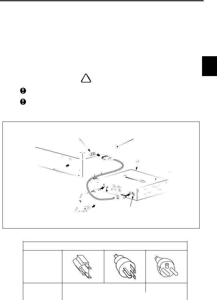
WIRING
1.Make sure that the power switch (2) of the power supply box (1) is OFF.
2.Insert the plug (4) of the DC power cord (3) securely into the power supply connector (5) of the embroidery machine.
3.Insert the other plug (6) of the DC power cord (3) securely into the DC power supply connector (7) of the power supply box (1).
4.Insert the plug (9) of the AC power cord (8) securely into the AC power supply connector (10) of the power supply box.
5.Insert the plug (11) at the other end of the AC power cord (8) securely into the single-phase 100 to 240 V power supply.
|
! WARNING |
|
|
0 |
Connect the earth wire of the AC power cord to the earth terminal |
0 |
It could cause electric shock unless the machine is grounded properly. |
The mains plug must be accessible after it is connected to the supply socket, so that it can easily |
|
|
be disconnected in an emergency. |
|
|
PREPARATION
(5) |
Embroidery machine |
|
(4)
DC power cord (3)
|
\\~ |
|
|
|
|
|
(9) |
|
|
||
|
\~ |
|
|
||
|
(10) |
|
|
||
|
|
|
|||
|
'-.....,:::::::=- ~ ~ ~~ |
(6) |
|||
|
|
|
|||
|
If AC power source |
(7) |
|||
AC power cord (8) |
(to the receptacle |
||||
|
|
||||
with earth terminal) |
|
|
|||
|
|
|
|||
 Power switch (2)
  (Switch: OFF position)
Power supply box (1)
Types of AC Power Cord
Plug
Spec. |
|
USA and Canada |
EU |
|
|
|
|
|
|
Voltage Rating |
125 V |
|
|
250 V |
|
|
|
|
|
13
From the library of Superior Sewing Machine & Supply LLC - www.supsew.com
PREPARATION
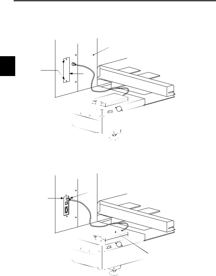
CONNECTING THE USB FDD (FLOPPY DISK DRIVE) (TO BE PURCHASED SEPARATELY)
1.Remove the pair of cover set screws (1) and then remove the connector cover (2).
2.Insert the plug (3) of the FDD securely into the USB connector (4) of the embroidery machine.
Embroidery machine
(1) 
(2)
(3)
(4)
Floppy disk drive
14
From the library of Superior Sewing Machine & Supply LLC - www.supsew.com
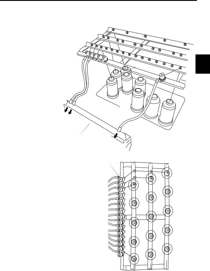
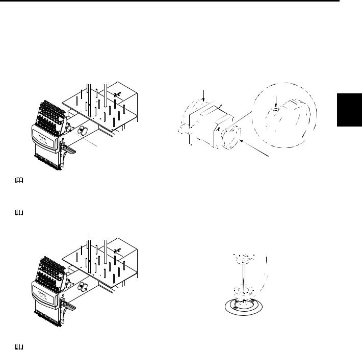
SETTING THE UPPER THREAD
Upper Thread Setting
Procedure
1.Pass the thread from the spool (1) through the hole on the thread guide (1) just above the spool (1) and further pass it through thread guides at the middle and front rows.
2.Pass next the thread through the sub thread tension regulator (1).
3.For spools (4), (7), (10) and (13), set the thread in the same manner up to the sub thread tension regulators of the same number.
4.Pass the thread from the spool (2), at the middle row, through the hole on the thread guide (2) just above the spool (2) and further pass it through the thread guide at the front row.
5.Pass the thread through the sub thread tension regulator (2).
6.For spools (5), (8), (11) and (14), set the thread in the same manner up to the sub thread tension regulators of the same number.
7.Pass the thread from the spool (3), at the front row, through the hole on the thread guide (3) just above the spool (3).
8.Pass next the thread directly through the sub thread tension regulator
(3).
9.For spools (6), (9), (12) and (15), set the thread in the same manner up to the sub thread tension regulators of the same number.
Fig. A Passing the Upper Thread: |
(1) |
Spool to Thread Guide
(2)
(3)
Tension base
Sub thread tension regulator (1)
Sub thread tension regulator (2)
Sub thread tension regulator (3)
(4) |
|
|
Thread guide |
|
|
(7) |
|
|
|
|
|
|
|
|
(5) |
|
(10) |
(13) |
|
|
|
|
||
(8) |
|
|
|
|
(6) |
|
(11) |
|
|
(9) |
|
(14) |
|
|
|
|
|
PREPARATION |
|
|
|
(12) |
|
|
|
|
|
(15) |
Spool (1)
|
Thread guide |
Front row |
Middle row Rear row |
 Spool (1)
 Spool (2)
(4)
(5) Spool (3)
(6)
(7)
(8)
(9)
(10)
(11)
(12)
(13)
(14)
(15)
15
From the library of Superior Sewing Machine & Supply LLC - www.supsew.com
|
10. |
Run the thread from the sub thread tension regulator (15) through the spiral tube (15). |
|
|
11. |
Run the thread further through the thread guide (15)-1, thread tension regulator (15) rotary sensor (15) and thread |
|
|
|
guide (15)-2. |
|
|
12. |
Open next the needle bar case cover. |
|
|
13. |
Raise the thread holder lever (GL), hook the upper thread on the thread holder (15) from right to bottom and pass |
|
|
|
the thread through the hole of take-up lever (15) at the top. |
|
|
14. |
After that, run the thread down and through the thread guide (15)-3, then through the hole of the needle (15) and |
|
|
|
finally through the hole in the presser foot (15). |
|
PREPARATION |
15. |
Hook next the thread end on the thread holding spring. |
|
16. |
Set the thread of spools (14) to (1) in the same manner. Finally, push down the thread holder lever (GL) down to |
||
|
finish the setting of upper thread.
Fig. B Passing the Upper Thread:
Thread Guide to Needle
Thread guide |
|
|
Thread guide (15)-1 |
Tension base |
|
|
Thread tension |
|
regulator (15) |
|
Rotary sensor (15) |
Needle bar |
Thread guide (15)-2 |
case cover |
|
|
TOYOTA |
|
EXPERT ESP9100NET |
Needle bar |
|
case |
|
Sub thread tension regulator (15)
Threader
Spiral tube (15)
Take-up lever (15)
Thread holder (15)
Thread holder lever (GL)
Thread guide (15)-3
Needle (15)
Thread holder spring |
Presser foot (15) |
16
From the library of Superior Sewing Machine & Supply LLC - www.supsew.com
SETTING THE UNDER THREAD
1.Orient the bobbin (1) with its thread facing in the direction, specified by the arrow symbol, and put it in the bobbin case (2).
2.Route the thread through the thread groove (3) in the bobbin case, under the thread tension spring (4) and the thread guard (5).
3.Raise the "lever" (6) on the bobbin case and then install it in the rotary hook.
NOTE: The standard under thread tension is 25 to 30 g (0.25 to 0.3 N) for the carbonized yarn #120.
The thread tension can be adjusted with the tension adjusting screw of the bobbin case. Turning the screw clockwise tightens the thread and turning it counterclockwise loosens the thread tension.
For adjustment, suspend three 25-cent coins from the bobbin case by taping them to the thread as shown in the illustration below. If thread is pulled out slightly when the bobbin case is gently shaken up and down, the thread tension is between 25 and 30 g (0.25 and 0.3 N).
PREPARATION
Thread groove (3)
Tension adjusting screw
Bobbin (1) Tension spring (4)
Bobbin case (2) 
Thread guard (5)
Lever (6)
! CAUTION
Before setting or removing the bobbin, be sure to turn OFF the power switch. Otherwise, the embroidery machine may start causing injury of operators.
17
From the library of Superior Sewing Machine & Supply LLC - www.supsew.com
PREPARATION
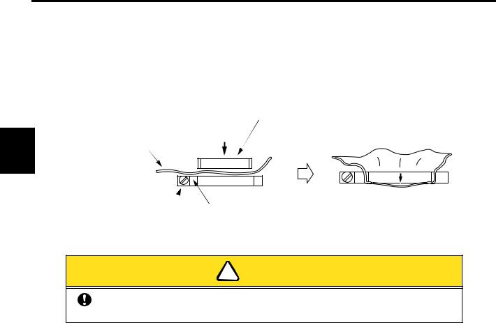
SETTING THE FABRIC ON THE HOOP
1.Place the fabric (2) on the outer hoop (1) and press the inner hoop (3) into the outer hoop (1).
If the inner hoop (3) cannot be pressed into the outer hoop (1) smoothly, loosen the hoop set screw (4).
2.Check if the fabric is correctly set in the hoop by pressing the center of the fabric gently with the finger as shown in the illustration below. The fabric should be stretched so that it returns to the state as before when the finger is released.
Inner hoop (3)
Fabric (2)
(Checking the setting of fabric)
Embroidery hoop set screw (4) Outer hoop (1)
! CAUTION
Make sure there is no hard item such as a button in the embroidery range. Otherwise, the needle may be broken causing injury of operators.
18
From the library of Superior Sewing Machine & Supply LLC - www.supsew.com
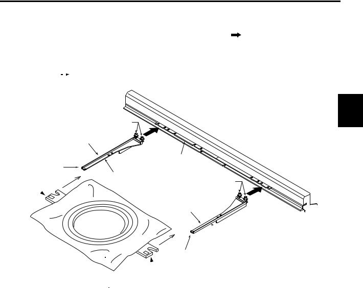
1.Attach two holder bases (1) to the joint plate (2) in the direction indicated by ...symbol and secure them in place with screws (3).
Determine the holder base (1) attaching position meeting the size of the hoop.
2.Insert the right and left metallic tabs of the embroidery hoop set in the sections A and B in the direction of dashed line arrows -- and fix the tabs by engaging the hoop presser springs (4) of the holder bases (1) in the tabs.SETTING
Screw (3) |
|
Hoop presser spring (4) |
|
|
Joint plate (2) |
A |
|
Holder base (1) |
Screw (3) |
Right hoop metallic tab |
Hoop presser spring (4)
 Holder base (1)
B
Left hoop metallic tab
Embroidery hoop set
PREPARATION
19
From the library of Superior Sewing Machine & Supply LLC - www.supsew.com
ATTACHING THE TABLE
1.Push in the table (1) till it hits the bottom with care to maintain equally at both right and left of top of the base cover
(2) on the embroidery machine.
2.Tighten the right and left fixing screws (3). This completes the attaching of the table.
PREPARATION
Fixing screw (3)
|
Base cover (2) |
Base |
Fixing screw (3) |
|
Table (1)
20
From the library of Superior Sewing Machine & Supply LLC - www.supsew.com
WINDING THE UNDER THREAD
1.Set a bobbin (2) on the under thread winding shaft (1).
2.Place the spool (3) on the spool stand on the cover, pass the thread end through the thread tension regulator guide (4) and wind the thread round the bobbin (2).
3.Press the thread winder lever (5) to the right so that it touches the inner face of the bobbin (2).
4.Thread is wound on the bobbin as the machine operates and the lever automatically returns back (turning to the left) when a certain amount of thread is wound on the bobbin to stop winding of the under thread.
Thread tension
regulator guide (4)
Under thread winding shaft (1) Bobbin (2)
Thread winder lever (5) |
Spool (3) |
|
 Cover
Cover
Spool stand
PREPARATION
Under thread may be used up during embroidery. In this case, set the under thread in the same manner as explained above.
21
From the library of Superior Sewing Machine & Supply LLC - www.supsew.com

CHECKUPS BEFORE STARTING OPERATION
Before starting the machine, carry out checkups as indicated below.
! CAUTION
Turn the main switch OFF before checking the machine prior to starting the operation.
If you check the machine without turning the main switch OFF, you could sustain injury.
PREPARATION
Check Point |
Description |
Action |
|
|
|
|
|
|
|
|
|
Covers |
Check for disengagement. |
Install if disengaged. |
|
|
|
|
|
Thread |
Check for disengagement. |
Set if disengaged. |
|
|
|
||
Check for breakage. |
Set if broken. |
||
|
|||
|
|
|
|
Needle |
Check for bend. |
Replace if bent. |
|
|
|
||
Check for breakage. |
Replace if broken. |
||
|
|||
|
|
|
|
Rotary hook rail |
Check if appropriate amount of |
Lubricate as required. |
|
oil applied. |
|||
|
|
||
|
|
|
22
From the library of Superior Sewing Machine & Supply LLC - www.supsew.com
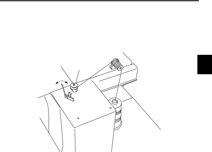
CHECKING THE EMBROIDERY HEAD
Check of the Color Change Device and Set Screw
The color change device selects needle bars. The machine will fail to operate if the color change cam is off the predetermined position (set screw is positioned right above or right below).
1.Turn the handle of the color change device to bring the set screw to the top position. Color change cam will be set at the fixed position.
Color change cam
Set screw
PREPARATION
Color change device
 Handle
m When the set screw of the handle is at the top position, an odd-numbered needle bar is selected.
Check of Needle Lowered Position
Check the needle lowered position only after checking the set screw position.
1.Turn the main shaft handle counterclockwise while pressing it against the arm.
2.When the needle enters the needle hole, check the needle location.
Needle 
Needle hole
 Handle
3.Make sure that the needle is located at the center of the needle hole.
If the needle is not positioned at the center, the needle could be bent. Replace it if necessary.
23
From the library of Superior Sewing Machine & Supply LLC - www.supsew.com
II
 OPERATION PROCEDURE
OPERATION BASICS
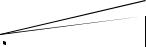
STARTING AND STOPPING THE MACHINE
Power Switch
The power switch is provided on the power supply box.
Press the power switch at "O" side to turn the power OFF or at "I" to turn the power ON.
OFF
ON
Power switch
PROCEDURE
OPERATION
MACHINE STOP Switch
Use the MACHINE STOP switch to stop the machine in an emergency. When the MACHINE STOP switch is pressed, the main shaft stops rotating and the MACHINE STOP switch is locked in the pressed state.
Turn the switch in the arrow direction to release the lock.
START and STOP Keys
The START key, when pressed, starts machine operation and the STOP key, when pressed, stops the machine.
The needle bar stops at the upper dead point when the STOP key is pressed.
START key STOP key
l

 0
0
START STOP
m
 When reapplying the power, turn the switch OFF and then turn it back ON after several seconds.
24
From the library of Superior Sewing Machine & Supply LLC - www.supsew.com
STEPS TO START EMBRODIERY
Example: To input the design data using the flat hoop from USB FDD (to be purchased separately)
1 Turn ON the power switch at the power supply box.
2 |
Select "FLAT" for "HOOP" using |
◄ and |
► (hoop travel keys). |
||
3 |
Select "ON" for "INITIAL" using |
◄ |
and |
► |
(hoop travel keys). |
4 |
Press the SET key. |
|
|
||
= = E SP 900 0 s er ies |
== |
|
|
|
|
|
||
HO OP |
|
F LA T |
|
|
|
|
Press |
. |
|
|
|
|
|
||||
|
|
|
|
|
|
|
||
IN ITI AL |
:O N |
< D> ICr |
• |
|||||
5 The screen displays "EMB START". Press the DATA set menu key.
== === E MB |
ST ART |
= === |
|
|
|
|
|
|
||
A I S I N 1 2 3 . 1 0 O 1 |
|
|
|
|||||||
I01 /15 : |
I |
|
0 / 10 |
27 |
|
|
|
|
Press |
. |
|
|
|
|
|
|
|
||||
23 |
- 4 567 89 A<D > |
|
|
|
||||||
|
|
|
|
|
|
|
|
|||
6For "INPUT DATA", select "USB" using ◄ and ► (hoop travel keys).
7Press the SET key.
== === D ATA M ENU |
= === |
|
|
|
|
|
||||
1 |
. INP UT |
DA TA |
|
|
U SB |
|
|
Press |
. |
|
|
|
|||||||||
2 |
. SEL EC T |
D AT A |
|
|
|
|
||||
|
|
|
|
|
|
|||||
3 |
. DEL ET E |
D AT A |
|
|
|
|
|
|
||
8Set the floppy disk in which the design data is stored to the FDD.
9Select the design data using ◄ and ► (hoop travel keys).
Example: AISIN123
10Press the SET key.
== == SE LEC T |
FIL E === |
|
|
|
|||||||
1 |
|
|
|
A I S I N 1 2 3 . 1 0 O |
|
|
Press |
. |
|||
|
|
|
|||||||||
ST ITC H |
|
|
10 |
713 |
S T |
|
|
|
|||
|
|
|
|
|
|
|
|||||
|
|
|
|
|
|||||||
ME MOR Y |
|
|
1 80 |
876 |
S T |
|
|
|
|||
|
|
|
|
|
|||||||
25
OPERATION |
PROCEDURE |
|
|
From the library of Superior Sewing Machine & Supply LLC - www.supsew.com
OPERATION PROCEDURE
11Input the needle numbers in the order of needle change using the numeric keys.
12Press the SET key.
== = |
C OL OR CH ANG E === |
|
|
|
|
|
|
||||
MO DE |
|
|
|
|
A UT O |
|
|
|
|
|
|
|
|
|
|
|
|
|
|
|
|
||
I |
|
: |
|
I |
Cr |
Press |
• |
||||
|
|
|
|
|
|
|
|
|
|
. |
|
01 /0 4: |
|
|
|
|
|
|
|
|
|
|
|
13The screen will display the information as shown below when the design data setting is completed.
== === E MB ST ART = ===
I |
A I S I N 1 2 3 . 1 0 O 1 |
I |
|||||
|
I |
|
|
* |
|
||
|
|
|
0 |
/ |
24 51 |
|
|
01 /04 : |
|
57 3 |
|
|
<D > |
|
|
14Set the fabric in the embroidery hoop.
15Set the embroidery hoop in the embroidery machine.
16Set the upper and under threads.
17Press the TRACE key to check if the range of embroidery fits the size and position of the embroidery hoop.
18If the hoop position does not fit the range of embroidery, adjust the position of the hoop using the hoop travel keys and repeat step 17 again.
If the hoop size does not fit the range of embroidery, change the hoop (to be purchased separately) to the one that fits the range of embroidery.
19After confirming that the hoop is set in the correct position, press the START key.
Embroidering starts up.
m Various kinds of setting can be made after completing the setting of design data.
26
From the library of Superior Sewing Machine & Supply LLC - www.supsew.com
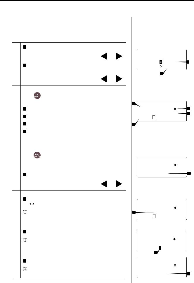
SCREENS
The LCD screen displays variety of information to navigate the operation. The information displayed on the LCD screen is briefly explained below.
● Basic Menu
•1 Hoop mode (FLAT / CAP / SLEEVE / BORDER / X-PANT)
PowerON |
• |
Change the selection with the hoop travel keys ◄and ►. |
"ON" (ON: Operated / OFF: Not) |
||
|
2 |
Start point return motion and initializing at the power switch |
Change the selection with the hoop travel keys ◄and ►.
*In automatic color change mode:
Use e to change the color change mode between automatic and manual.
|
•1 |
File name |
|
Embroideryof |
•2 |
Forward/Back travel unit (1/10/100/C/n-ST) |
|
• Needle bar numbers in the order of color change |
|||
|
•3 |
Present number of stitches / Total number of stitches |
|
|
4 |
Present step / Total number of steps: |
|
Start |
|
<Current needle bar number> |
|
|
|
||
* In manual color change mode: |
|||
|
|||
Atthe |
Use e to change the color change mode between auto- |
||
|
matic and manual. |
||
•1 Needle bar No.
Change the selection with the hoop travel keys ◄and ►.
Embroidering |
w |
Set for "1. SCREEN" of FUNCTION MENU. |
|||||||
|
1 |
|
|
Present number of stitches / Total number of stitches (ST) |
|||||
During |
• |
~ |
Present number of stitches / Maximum speed (RPM) |
||||||
|
|
|
|
|
|
|
|
||
|
|
|
|
|
|
|
|
||
|
|
|
|
|
|
|
|
|
|
Stop |
•1 Stop due to pause code |
||||||||
|
|
rn |
|
|
Insert "-" : Pause in the needle bar setting. |
||||
|
|
|
|
||||||
|
|
||||||||
Machine |
|
|
|
|
|
|
|
|
|
•Needle bar No. |
|||||||||
During |
|||||||||
|
1 |
|
|
|
|
||||
|
r |
n |
|
If "MANUAL" is selected for color change, the machine stops at |
|||||
|
|
||||||||
|
|
||||||||
|
|
|
|||||||
|
|
|
|
|
|
|
each color change operation. |
||
27
== == ES P91 00 NET |
= === |
|
HO OP |
E FL AT |
1 |
IN ITI AL ON |
< D> |
|
|
2 |
|
1 |
== == = E MB |
ST ART |
= === |
|
||
|
A I S I N 1 2 |
3 . 1 0 O |
.....,1 |
2 |
||
|
01 /1 5: |
|
2 3 |
0 / 10 |
27 |
3 |
|
I |
- 4 56 789 A< D> |
|
|||
4 |
|
|
|
|
|
|
== == = |
E MB ST ART |
= === |
|
|
|
|
|
..... |
|
A I S I N 1 2 3 . 1 0 O ..,1 |
|
|||
I01 /1 5: |
0 / |
10 |
27 |
]1. |
NO . |
2 |
|
||
== = EMB ROI DE RIN G === |
|
|||||||
A I S I N 1 2 3 . 1 0 O |
.....,1 |
|
||||||
1 |
66 / |
900 |
r pm |
|
||||
.[01 /1 5: |
|
2 3 - 4 56 789 A< D> |
I |
|||||
I |
||||||||
|
||||||||
= === = |
EMB P AUS E |
=== = |
|
|||||
A I S I N 1 2 3 . 1 0 O |
.....,1 |
|
||||||
|
15 9 / |
1 02 7 |
|
|||||
I0 1/1 5:123 |
J |
45 678 9A <D> |
I |
|||||
|
.- |
|
|
|
|
|||
|
1 |
|
|
|
|
|
||
== == = |
E MB PA USE |
= === |
|
|||||
A I S I N 1 2 3 . 1 0 O |
.....,1 |
]1. |
||||||
|
159 / |
10 27 |
||||||
I01 /1 5: NO . 4 |
|
|
||||||
OPERATION |
PROCEDURE |
|
|
From the library of Superior Sewing Machine & Supply LLC - www.supsew.com
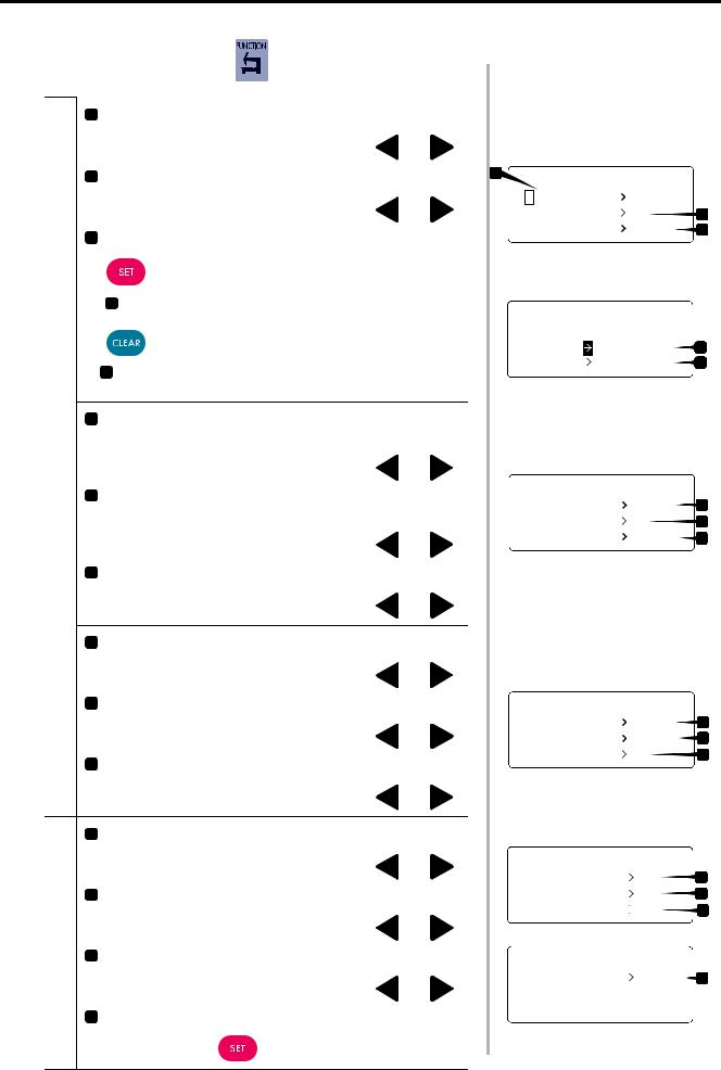
● Function Menu: Pressing |
in "EMB START" mode. |
OPERATION PROCEDURE |
Menu |
|
|
|
Function |
Function Menu
•1 |
Screen (ST: Stitch / rpm: Speed) |
◄ |
|
► |
|
|
•2 |
Change the selection with the hoop travel keys |
and |
. |
|||
Thread breakage sensor (OFF / 1 - 5) |
|
|
||||
•3 |
Change the selection with the hoop travel keys |
◄ |
and |
► |
. |
|
Bobbin counter |
|
|
||||
|
•• |
to set the bobbin counter. |
|
|
|
|
|
|
|
|
|
|
|
a Counter data (Actual accumulated value): Max. 999999 stitches•
(Can be cleared)
•b Preset data (Preset accumrated value): Max. 999999 stitches by Numeric keys
•4 Lock stitch (So: Yes at start / S-: No at start; Eo : Yes at end / E-: No at end)
|
Change the selection with the hoop travel keys |
◄ |
and |
► |
. |
||
5 |
Satin stitch adjustment |
|
|
|
|||
• |
(-: No adjustment / 1 - 5: Adjustment in 0.1 mm units) |
|
|
||||
•6 |
Change the selection with the hoop travel keys |
◄ |
and |
► |
. |
||
Slow start (2 - 9 stitches) |
|
|
|
||||
|
Change the selection with the hoop travel keys ◄and ►. |
||||||
7 |
Trimming in jump (0 - 9 stitches) |
|
|
|
|
|
|
• |
Change the selection with the hoop travel keys |
◄ |
and |
► |
. |
||
•8 |
|||||||
Jump length (OFF / 4.0 - 9.9 mm) |
|
|
|
||||
•9 |
Change the selection with the hoop travel keys |
◄ |
and |
► |
. |
||
Trimming length (1 - 17) |
|
|
|
||||
|
Change the selection with the hoop travel keys ◄and ►. |
||||||
•A Trimming timing (–10 - +10) |
|
◄ |
|
► |
|
||
|
Change the selection with the hoop travel keys |
and |
. |
||||
•B Boring (OFF / 1 - 2) |
|
|
|
||||
|
Change the selection with the hoop travel keys |
◄ |
and |
► |
. |
||
•C Cording (OFF / ON) |
|
|
|
||||
|
Change the selection with the hoop travel keys |
◄ |
and |
► |
. |
||
•D Sequin |
|
|
|
||||
|
Press the SET key • . |
28 |
|
|
|
|
|
1 |
== = FUN CTI ON ME NU |
== |
|||
|
|||||
|
1 |
|
S CRE EN |
S T |
|
|
|
|
|||
|
2 |
. TH REA D |
S NS 2 |
2 |
|
r3 |
. BO BBI N |
C NT [S ET]l3 |
|||
=== BOBBIN COUNTER == |
||||
I |
C OU NTE RE 1 27 8 |
|
S T |
a |
P RE SET 3 000 |
0 |
ST |
b |
|
|
|
|
1 |
|
== = FUN CTI ON |
ME NU == |
|||
4 |
. LO CK |
ST . |
So |
Eo 4 |
5 |
. SA TIN |
AD J . 2 |
5 |
|
I6 |
. SL OW |
STA RT 2 |
ST i6 |
|
== = FUN CTI ON |
ME NU |
== |
|
||
7 |
. TR IM |
JUM P |
3 ST |
|
7 |
8 |
. JU MP |
LNG TH |
6 . 0mm |
8 |
|
I9 |
. TR IM |
LNG TH |
3 |
J9 |
|
== = FUN CTI ON |
ME NU |
== |
|
A . TR IM TMN G |
+ 0 |
A |
|
B . BO RIN G |
O FF |
B |
|
I |
|
|
C |
C . CO RDI NG |
O FF |
||
== = FUN CTI ON |
ME NU |
== |
|
D . SE QUI N |
|
[ SET ] D |
|
|
|||
I
From the library of Superior Sewing Machine & Supply LLC - www.supsew.com
|
● Hoop Menu: Pressing |
in "EMB START" mode. |
|
|
|
||||
|
|
|
|
|
|
||||
|
|
•1 |
Hoop type (FLAT / CAP / SLEEVE / BORDER / X-PANT) |
|
|||||
|
|
•2 |
Change the selection with the hoop travel keys |
◄ |
and |
► |
. |
||
|
|
Initialization (ON / OFF) |
|
|
|
||||
|
|
|
Change the selection with the hoop travel keys |
◄and |
►. |
||||
|
|
3 |
Start point return after embroidering (AUTO / MANUAL) |
► |
|
||||
Menu |
|
|
|
|
_:◄~ |
|
|||
|
|
• Change the selection with the hoop travel keys |
|
and |
|
. |
|||
Hoop |
|
4 |
Hoop travel speeds (1 - 3) in the manual mode |
|
|
|
|
||
|
|
|
|
|
|
||||
|
|
•5 |
Change the selection with the hoop travel keys |
◄ |
and |
► |
. |
||
|
|
Hoop drive start timing (AUTO / 250° ) |
|
|
|||||
|
|
•6 |
Change the selection with the hoop travel keys |
◄ |
and |
► |
. |
||
|
|
Offset (AUTO / MANUAL) |
|
|
|||||
|
|
|
Change the selection with the hoop travel keys ◄and ►. |
||||||
|
|
|
|
|
|
||||
|
|
|
|
|
|
|
|||
|
● Edit Menu: Pressing |
in "EMB START" mode. |
|
|
|
||||
|
|
|
|
|
|
|
|
|
|
|
|
•1 |
Size X |
|
◄ |
and |
► |
. |
|
|
|
•2 |
Change the selection with the hoop travel keys |
||||||
|
|
Size Y |
|
and |
. |
||||
|
|
•3 |
Change the selection with the hoop travel keys |
◄ |
► |
||||
|
|
Rotation (45° units) |
|
and |
. |
||||
|
|
•4 |
Change the selection with the hoop travel keys |
|
► |
||||
Menu |
|
Mirror (OFF / X (X-axis mirror) / Y (Y-axis mirror))◄ |
|
|
|||||
|
|
Change the selection with the hoop travel keys |
◄and |
►. |
|||||
|
|
• • |
|
|
|
|
|
||
Edit |
|
5 |
Repeat |
|
|
|
|
|
|
|
|
|
|
|
|
|
|
|
|
|
|
* Repeat setting |
|
|
|
|
|
||
|
|
|
•a Direction of repeat (HORIZONTAL / VERTICAL) |
and |
|
. |
|||
|
|
|
Change the selection with the hoop travel keys |
◄ |
► |
||||
|
|
|
•b Number of repetition times (01 - 99) |
and |
|
||||
|
|
|
Change the selection with the hoop travel keys |
◄ |
► |
. |
|||
|
|
|
•c Repeat space (0 - 255 mm) |
|
|
||||
|
|
|
Change the selection with the hoop travel keys ◄and ►. |
||||||
29
I
== == = H OOP M ENU = === |
|
||||
1 |
|
H OOP |
|
* FLA T |
1 |
|
|
||||
|
|
||||
2 |
. IN ITI ALI ZE |
|
ON |
2 |
|
|
|||||
I3 |
I |
|
|
3 |
|
. ST ART PN T |
|
AU TO |
|||
|
|||||
I |
|
|
|
:l |
OPERATION PROCEDURE |
||||
== == = |
H OOP |
M ENU = === |
|
||||||
|
|
||||||||
4 |
|
M ANU AL SP D |
|
1 |
4 |
|
|||
I |
|
||||||||
|
|
||||||||
5 |
. HO OP |
TMN G |
|
|
|
AU TO |
5 |
|
|
|
|
|
|
||||||
6 |
. OF FSE T |
|
|
|
AU TO |
6 |
|
||
|
|
|
|
||||||
|
|
|
|
|
|
|
|
|
|
=== == |
ED IT |
ME NU == == |
|
|||
|
|
|
|
|
||
1 |
|
SI ZE |
X |
|
10 0% |
1 |
|
|
|||||
2 . S IZ E |
Y |
|
100 % |
2 |
||
|
||||||
I3I. R OT ATE |
|
270 |
3 |
|||
|
||||||
=== == |
ED IT |
ME NU == == |
|
|||
I |
|
|
|
|
|
|
I |
|
|
|
|
||
4 |
|
MI RR OR |
|
OF F |
4 |
|
5 . R EP EAT |
|
[SE T] |
5 |
|||
|
||||||
== |
RE PE AT |
SE TTI NG == |
|
|
PR IOR |
E HO RIZ ON TAL |
a |
||
X |
TIM ES |
1 |
b |
|
IY |
TIM ES |
1 |
c |
|
I
From the library of Superior Sewing Machine & Supply LLC - www.supsew.com
 Loading...