


8FGDU15-32

ELECTRICAL SYSTEM TROUBLESHOOTING
8FG(D)U15-32, 8FGCU20-32
Page
BEFORE TROUBLESHOOTING..........................19-2
CONNECTOR HANDLING.......................................19-2
WIRE HARNESS AND CONNECTOR
INSPECTION PROCEDURE
..................................19-2
19-1
0
1
2
TROUBLESHOOTING..........................................19-4
BEFORE BEGINNING TROUBLESHOOTING
FOR THE 4Y-E ENGINE
DIAGNOSIS (SELF DIAGNOSIS FUNCTION) ............19-5
DIAGNOSIS DISPLAY METHOD..............................19-5
LIST OF DIAGNOSIS CODES..................................19-6
WARNING LIST ...................................................19-12
VIEWING RELATED PORTIONS............................19-13
ERROR CONFIRMATION DRIVE MODE .................19-13
TROUBLESHOOTING BY ERROR CODE...............19-14
TROUBLESHOOTING WHEN THERE IS
NO ERROR CODE
...........................................19-156
........................................19-4
3
4
5
6
7
8
9
10
11
12
13
14
15
16
17
18
19
20
21
E
Service Manual Change History
Description Page # Date
Revised error code for change in terminal
1
esignation on seat switch from X1-1, X1-2 to 05Page not required foerror code A5-1 and turned
2
into memo page
3Added bookmarks all 3/31/13
4Added SIB CE07-008 197 3/31/13
5Added SIB CE08-005 195, 196 3/31/13
6Added SIB CE09-004 199 3/31/13
7Added SIB CE10-005 198 3/31/13
19-111 12/15/09
19-112 12/15/09
Service Information Buletin
1 SIB CC08-005 4Y ECS Controller Programming Change Chapter 19
2 SIB CE07-008 Error Code AD-1 and AD-7 Chapter 19
3 SIB CE09-004 A5, A5-1 or 1-1 Error Codes For OPSS Chapter 19
4 SIB CE10-003 Horn Relocation Chapter E2
5 SIB CE10-005 Main Wiring Harness Change (Error Code 73-1) Chapter 19
6 SIB CE11-001R Clamp Release Interlock (Mini Lever Units) Chapter 19, 14, E3
7 SIB CE11-003 Clamp Release Interlock (Standard Lever Units) Chapter 14, E3
8 SIB EN07-001 4Y Engine Ignition Timing Procedure Chapter 1.3-10
9 SIB EN08-001 Repair Manual (00700-X8880-71) Revision Embedded
10 SIB EN08-002 Repair Manual (00700-X8880-71) Revision Embedded
11 SIB EN09-001 Repair Manual (00700-X8880-71) Revision Embedded
12 SIB EN09-002 Repair Manual (00700-X8880-71) Revision Embedded
13 SIB EN10-001 Engine Block Heaters Chapter 1.2-4
14 SIB FS08-001 LPG Regulator Chapter 1.3-2
15 SIB HS07-003 Flow Regulator Replacement Parts Chapter 14
16 SIB MA07-001 Hourmeter Fuse Installation Chapter 0
17 SIB MA07-003 Transmission Oil Level Inspection Chapter 2 & 2.1
18 SIB MA07-004R Grease Specifications Chapter 0
19 SIB MA10-001 Overhead Guard Mounting Bolt Torque Chapter 9
20 SIB MA10-007 Oil Pressure Switch Chpater 0 & E3
21 SIB MA11-001 Service Hint For Greasing Rear Axle Beam Pivot Pin Chapter 0
22 SIB MA13-001 Exhaust Mounting Clamp with Rubber Bushing Inspection Chapter 0
23 SIB RA08-001 Updated Horn Pad Chapter 7
24 SIB ST07-001 Special Service Tools Chapter 17
25 SIB TR07-001 Transmission Control Valve Identification Chapter 2 & 2.1
26 SIB TR07-002 Propeller Shaft Cover Chapter 2 & 2.1
Technical News Brief
1 TNB 2007-03R1 Hydraulic Oil Change
2 TNB 2007-05 Transmission Knocking Noise At Idle
3 TNB 2007-06 LPG Regualtor Slow Path Tamper Resistant Cap
4 TNB 2007-11 Torque Specificaion Of Outer Mast Support Bolts
5 TNB 2008-07 Fuel Mixture Adjustment Procedure For The 4Y ECS Engine
6 TNB 2008-20 Gasoline Fuel System
7 TNB 2008-12 Installation of Fuel Line Fittings
8 TNB 2009-03 Suppliment to TNB 2008-07 For Adjusting VF (Voltage Fuel)
Hotline Tech Tips
1 HTT 2007-02
2 HTT 2007-03
3 HTT 2007-04
4 HTT 2007-05
5 HTT 2007-06
6 HTT 2007-07
7 HTT 2007-08
8 HTT 2007-09
9 HTT 2007-10
10 HTT 2007-11
Transmission Control Valve Identification; Proper Chasis Lubrication
Idle Surge/Hunt; Quick Facts; Rotten Egg/Ammonia Smell
Limiting Travel Speed; A5-1 Code
LPG Regulator Adjustment; Engine/Transmission "Knocking" Complaint
Troubleshooting Diesel Smoke; Multifunction Display
LPG Regulator Maintenance
Engine Surge
Propshaft Cover
Error Code 68-3; Flow Regulator Valve Parts Replacement
Wet Brake Option Hydraulic Oil; Error Code AD-1 And AD-7

11 HTT 2007-12
12 HTT 2008-01
13 HTT 2008-02
14 HTT 2008-03
15 HTT 2008-04
16 HTT 2008-05
17 HTT 2008-06
18 HTT 2008-07
19 HTT 2008-08
20 HTT 2008-09
21 HTT 2008-10
22 HTT 2008-11
23 HTT 2008-12
24 HTT 2009-01
25 HTT 2009-03
26 HTT 2009-06
27 HTT 2009-07
28 HTT 2009-08
29 HTT 2009-09
30 HTT 2009-10
31 HTT 2009-11
32 HTT 2010-01
33 HTT 2010-02
34 HTT 2010-03
35 HTT 2010-04
36 HTT 2010-05
37 HTT 2010-06
38 HTT 2010-07
39 HTT 2010-08
40 HTT 2010-09
41 HTT 2010-10
42 HTT 2010-11
43 HTT 2010-12
44 HTT 2011-01
45 HTT 2011-02
46 HTT 2011-03
47 HTT 2011-04
48 HTT 2011-05
49 HTT 2011-06
50 HTT 2011-07
51 HTT 2011-08
52 HTT 2011-09
53 HTT 2011-10
54 HTT 2011-11
55 HTT 2011-12
56 HTT 2012-01
Horn Pad Improvements; Correct Timing Mark On Crank Pulley
"L-OFF" Complaint
Error Code List; Rear Pillar Assist Relay Location; New Cab
Carriage Roller Replacement
Fuel Shut Off Valve Orientation On Gasoline And Dual Fuel Trucks
Driveability Issues Due To Dirty Throttle Body
Shift Interlock (Intelli-Shift) Adjustments; Overheat Trouble Shooting
LPG Tamper Resistant Cap
Cam Positions Sensor
SAS Matching; Transmission Repair
Seatbelt Interlock; Function Menu w/ Travel & Load Handling Option; Gas Tank Pressure
Accelerator Sensor Codes; LPG Filter Kit Service Parts
CNG Trucks Using The Analyzer; Extra Long Feeler Gauges for Mast Shimming Checks
Error Code 73-1, Or Missing Plug On New Harness
Load Sensor Wire Breakage; Dual Brake Pedal "Low Pedal" Complaint
Error Code OB-1
Horn Pad Improvements; Flow Regulator Update; Overheat Diagnostics
Engine Controller Version Identification
Identifying LPG Regulator 1st Valve Material; High Engine Idle Issues
Using the Engine Analyzer To Check The Engine Function
Error Codes Without An Hour Meter Reading; LPG Filter Kit PN
Reverse Polarity Damage Issues
Ignition Timing Value (IGT) Shown On Analyzer
Error Code 06-3; Error Code 01-5
To Throttle Valve Actuation And Error Code 06-3 E-THRO Fuse Location
Error Code AD-7 After Replacing The Main Harness
SAS Manual Lowering Valve Location; Flow Regulator W/ Part Numbers
SAS Code History Check Without The Analyzer
Clearing 01-1, 01-2, 01-3, 01-4, 01-5, 01-6 Codes After Making The Repair
Error Code 73-1 After Replacing The Main Harness
Hour Meter Diagnostics & Memory
Diagnosing Diesel Smoke
LPG Regulator Adjustment & Tar Draining: Idle Speed Adjustment
How To Read An O2 Sensor
Required Adjustments For New LP Regulator, And Installation Of Anti-Tamper Caps
Engine Analyzer Screen 1/10; Throttle Body Cleaning
Engine Analyzer Screen 2/10; Analyzer Speed Versus Displayed Speed
Engine Analyzer Screen 3/10
Engine Analyzer Screen 4/10
Engine Analyzer Screen 5/10
Engine Analyzer Screen 6/10
Engine Analyzer Screen 7/10
Engine Analyzer Screen 8/10
Engine Analyzer Screen 9/10
Engine Analyzer Screen 10/10
Error Code 09-1; LPG Filter Kit; Cold Soak Lack Of Travel

19-219-2
Electrical System Troubleshooting
Section 19
BEFORE TROUBLESHOOTING
CONNECTOR HANDLING
1. Disconnect the battery plug before connecting or
disconnecting each connector or terminal.
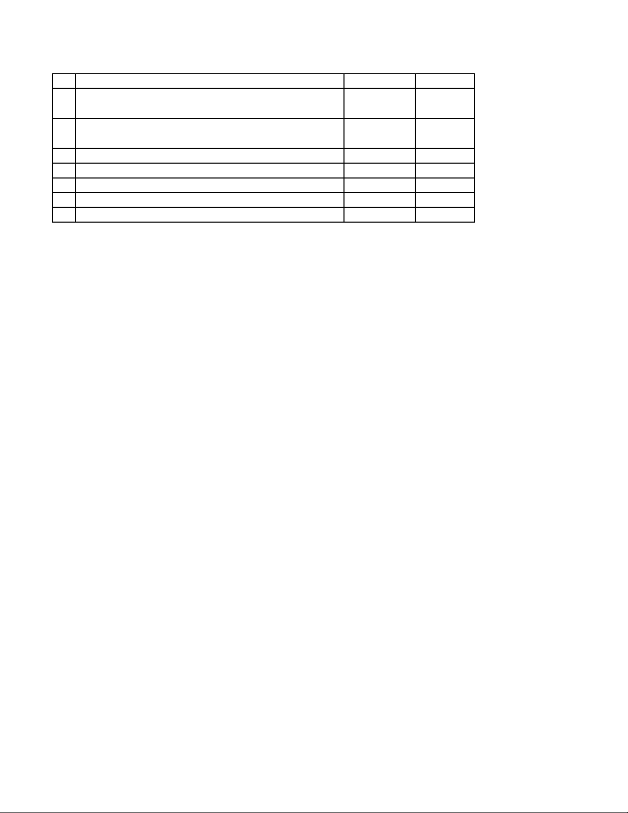
2. When disconnecting a connector, do not pull the wire harness
but hold the connector itself and pull it after unlocking it.
To connect, push the connector fully until it is locked in
position.
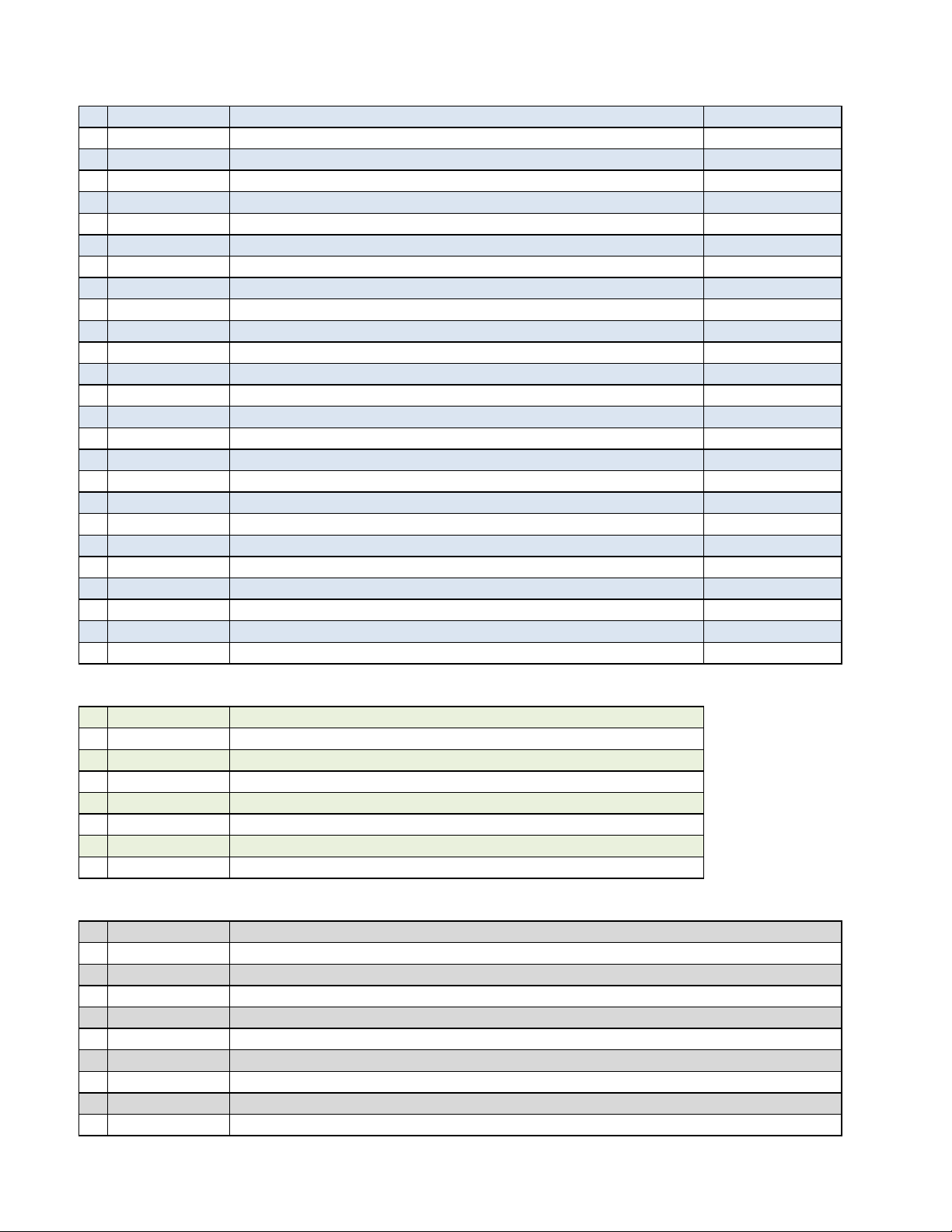
3. Bring a tester probe into contact with a connector terminal from
the rear side of the connector (harness side).
4. If insertion from the rear side is impossible, as in the case of a
waterproof connector, bring the tester probe carefully into
contact with the terminal so as not to cause deformation of the
connector terminal.
5. Do not touch connector terminals directly with your hand.
6. When bringing tester probes into contact with terminals that
voltage is applied to prevent two tester probes from coming
into contact with each other.
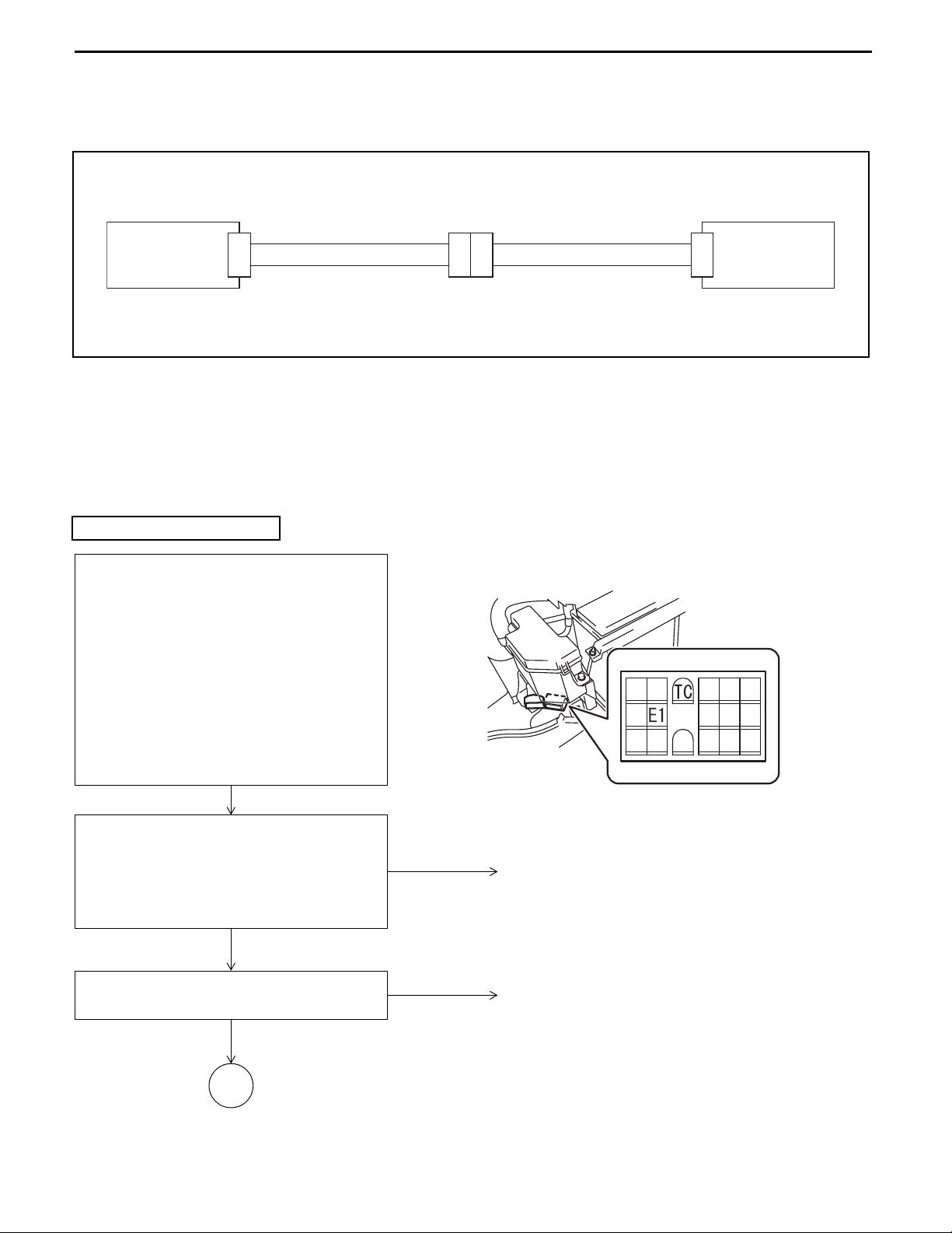
WIRE HARNESS AND CONNECTOR
INSPECTION PROCEDURE
When any trouble occurs, first inspect the connectors and wire
harness of the related circuit according to the following procedure:
Continuity Inspection
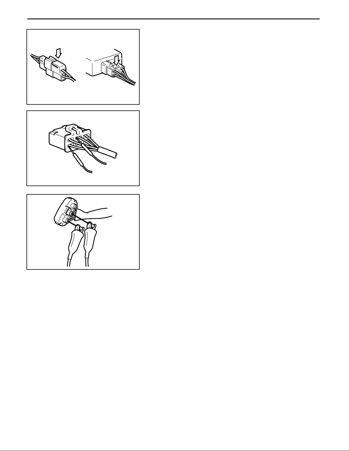
1. Disconnect the connectors at both ends of the corresponding
harness.
2. Measure the resistance between corresponding terminals of
the connectors at both ends.
Standard: 10 Ω or less
Note:
• Measure while jiggling the wire harness up and down and
sideways.
• Open circuit at the wire harness occurs rarely partway
through a vehicle wiring but mostly at connectors. Inspect
especially the sensor connectors with sufficient care.
19-3
Electrical System Troubleshooting
Section 19
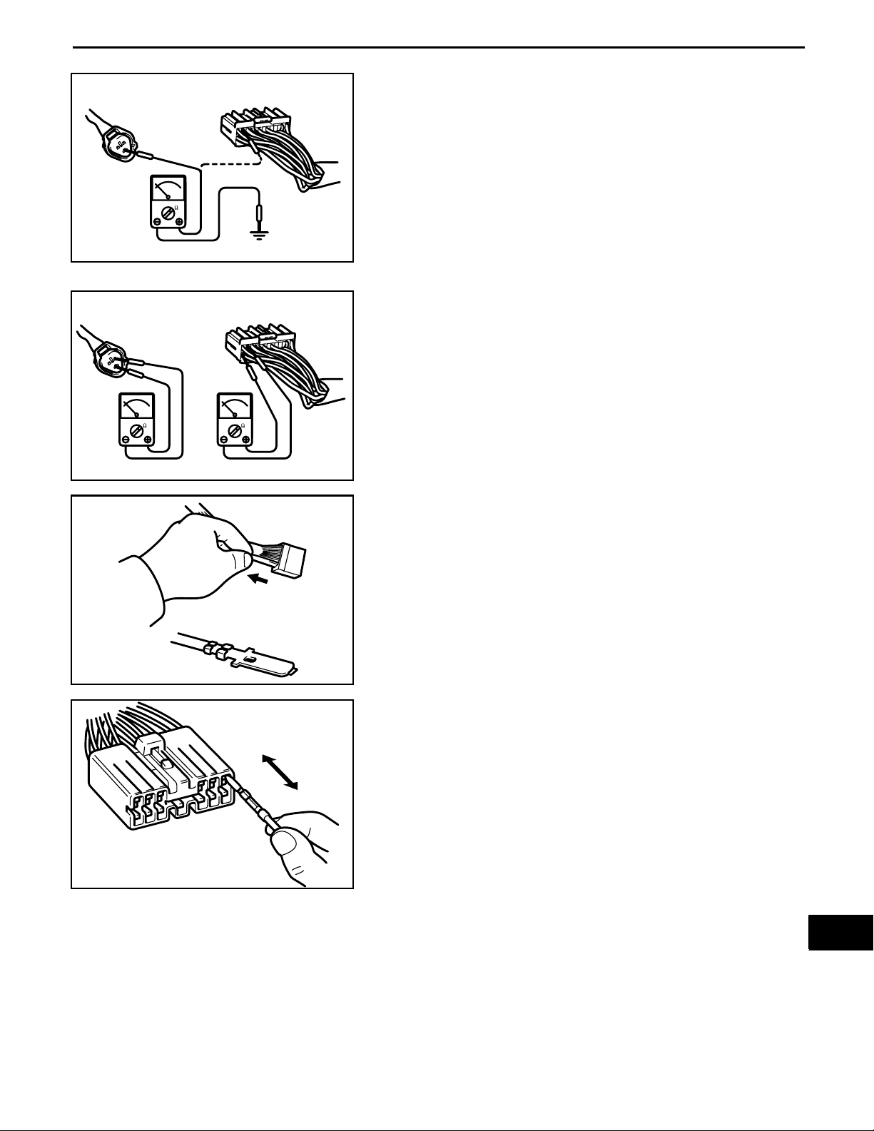
Short Circuit Check
1. Disconnect the connectors at both ends of the corresponding
harness.
2. Measure the resistance between the corresponding connector
terminal and frame. Be sure to inspect the connectors at both
ends.
0
Standard: 1 MΩ or above
Note:
Measure while jiggling the wire harness up and down and
sideways.
3. Measure the resistance between terminals of the
corresponding connector. Be sure to inspect the connectors at
both ends.
Standard: 1 MΩ or above
Note:
The wiring may short-circuit due to pinching by the body or
defective clamping.
Visual and Contact Pressure Checks
1. Disconnect the connectors at both ends of the corresponding
harness.
2. Visually inspect that there is neither rust nor foreign matter
trapped at connector terminals.
3. Inspect that there is no looseness or damage at the crimped
portion. Also, lightly pull the wire harness from the connector to
check that it does not come off.
1
2
3
4
5
6
7
8
9
10
11
12
4. Insert a male terminal same as that of the connector terminal
to a female connector and check the drawing force.
Defective contact may exist at a terminal where the drawing
force is less than that of other terminals.
Note:
Even if there is rust or foreign matter trapped at the terminal,
or the contact pressure between male and female terminals is
low, abnormal contact condition may be changed to normal by
disconnecting and reconnecting the connector. In this case,
disconnect and reconnect the connector several times, and if
a fault occurs even once, then consider the terminal may have
a defective contact.
13
14
15
16
17
18
19
20
21
E
19-419-4
Electrical System Troubleshooting
Section 19
TROUBLESHOOTING
BEFORE BEGINNING TROUBLESHOOTING FOR THE 4Y-E ENGINE
It is extremely risky to begin troubleshooting for the 4Y engine on the basis of results only. It can lead to mistaken
corrective action, wasted time, and sometimes to an increase in abnormalities. Therefore, ask the customer about
detailed information on conditions around the time a problem occurred, based on the following.
Diagnostic Procedure
First, it is necessary to be informed of the "fault history and service history" for the vehicle, and then to gather definite
information about the fault occurence such as "when", "at what times", "in what places", "during what operations or
actions", "what happened afterwards", and “frequency of occurrence”.
Also, try to recreate the conditions for the fault occurence. (a. Recreation impossible b. Recreation possible: in what
condition?)
• General items
Customer name Date of delivery Date fault occurred / hour meter reading
Vehicle model Frame No. Engine No. (punched)
Fuel type
F Gasoline F LPG F Gasoline - LPG combination (Note LPG fuel company name: )
• Condition of the defect (Tick the items that apply)
Defect phenomena
1. Cannot start a. Does not crank b. Combustion does not start c. Incomplete combustion
2. Does not start well Poor cranking (when cold - when warm - at all times)
3. Poor idle a. Poor idle speed b. Unstable idle speed c. Hunting (regular fluctuation in speed)
a. Immediately after start-up (when cold - when warm) b. During deceleration c. After deceleration
4. Engine stalling
5. Defect operational
status
6. Other
Environment at the time of the defect's occurrence
The time when the fault
began to occur
Frequency of occurence a. Always b. Under certain conditions c. Sometimes
Weather
Temperature conditions Coolant: a. When cool b. When warm Temperature inside engine room: °C
Operation conditions
Lamps a. Lights constantly b. Lights occaisonally c. Does not light
d. Without sign e. After the engine has been running rough f. When steering
g. When handling materials h. Can be re-started immediately
a. Insufficient power output b. Hesitation
c. Surging (swaying forward and backward during acceleration) d. Knocking e. Backfiring f. After
firing
a. Excessive fuel consumption b. Excessive oil consumption c. Overheating d. Water or oil leaks
e. Abnormal noise f. Other ( )
a. Since the vehicle was new b. Recently (from around the following date (month and year): )
c. After being serviced
Sunny - cloudy - rain - snow thunderstorm
a. No relation b. When idling c. When revving d. When accelerating
e. When traveling at constant speed f. When decelerating g. When climbing a slope
h. During material handling operations When not loaded (when steering - when lifting - when tilting)
When loaded (load: appox. kg) (when steering - when lifting - when tilting)
i. Other (when using the inching brake - when steering - other)
Temperature
Approximately
°C
Humidity
Approximately
%
19-5
Electrical System Troubleshooting
Section 19
DIAGNOSIS (SELF DIAGNOSIS FUNCTION)
General
When the computer detects a problem in the system, the fault is indicated by lighting a warning lamp on the
combination meter and displaying an error code. And fail-safe functions are started automatically to stop the engine
or control the engine to a low speed.
0
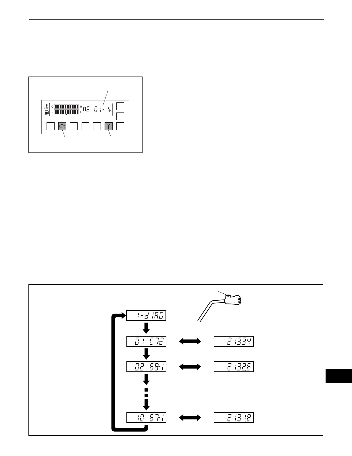
DIAGNOSIS DISPLAY METHOD
Error code display
An orange colored lamp lights
(Engine ECU only)
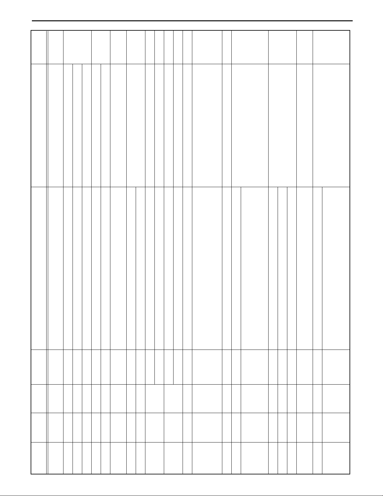
2. Diagnosis memory display method
To display the diagnosis memory display, there are a method using the hour meter and tilt lever, a method using
the optional display, and a method using a plug-in analyzer.
Here the display method using the hour meter and tilt lever is described.
(1) From the main menu, display the diagnosis memory menu. For how to display the main menu, refer to page
18-30.
(2) A diagnosis No. and error code are displayed each time the knob switch is pressed and released. Each
error code and the time at which it occurred are displayed alternately at 2 second intervals.
Note:
• The maximum number of error codes that can be stored is 10. The smaller the diagnosis No., the more
recent the error is.
• The stored time of an error code appearing just when the ignition key switch is turned ON may be stored
as 0.0.
Lamp blinks
1. Diagnosis display method
The diagnosis is displayed by means of an error code as
shown in the illustration to the left, and by the lights turning on.
When the ignition key switch is turned ON, the lamp lights
once to allow checking for the bulb, and then turns off again if
the status is normal.
With the ignition key switch ON, if an abnormality is detected
when the vehicle is stopped, travelling or performing meterials
handling operations, an error code is displayed and the lamps
turn on as a warning.
When this happens, stop the vehicle immediately and check
the error code.
1
2
3
4
5
6
7
8
9
10
11
12
(3) Connect the matching connector and turn the ignition key switch OFF.
Knob switch
Diagnosis memory menu
Press the knob switch to return it.
Switches automatically
every 2 seconds
13
14
15
16
17
18
19
20
21
E

19-6
Electrical System Troubleshooting
Section 19
Described
19-14
on page
19-18
The engine speed is unstable and it may stop.
19-27
The engine may have a problem at low
temperatures.
The engine may have a problem 19-29
19-31
The engine may have a problem at low
temperatures.
19-33
Limting speed of traveling and materials
handling due to limited engine power output
19-35
19-37
Limting speed of traveling and materials
handling due to limited engine power output
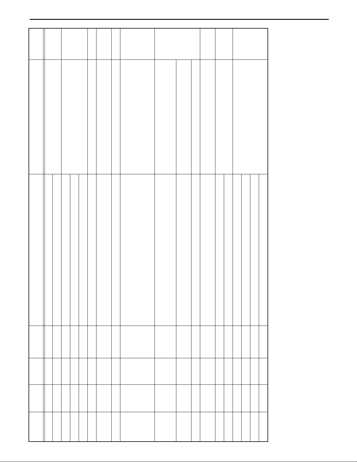
19-470A-2 0A-2 Blinking 4Y-ECS Fuel specification changeover switch error Display only
Error mode Phenomenon on vehicle
ECU
Detection
Spanner
lamp
Wrench
01-1 01-1 Blinking 4Y-ECS Fuel feedback control error (gasoline) rich
Indication
LIST OF DIAGNOSIS CODES
01-2 01-2 Blinking 4Y-ECS Fuel feedback control error (gasoline) lean
01-3 01-3 Blinking 4Y-ECS Fuel feedback control error (LPG/CNG) rich
01-4 01-4 Blinking 4Y-ECS Fuel feedback control error (LPG/CNG) lean
01-5 01-5 Blinking 4Y-ECS O2 sensor open abnormality The engine speed is unstable and it may stop. 19-23
01-6 01-6 Blinking 4Y-ECS O2 sensor heater open abnormality Display only 19-25
02-1 02-1 Blinking 4Y-ECS Intake temperature sensor open abnormality
02-2 02-2 Blinking 4Y-ECS Intake temperature sensor short abnormality
03-1 03-1 Blinking 4Y-ECS Intake pipe pressure sensor open abnormality
03-2 03-2 Blinking 4Y-ECS Intake pipe pressure sensor short abnormality
04-1 04-1 Blinking 4Y-ECS Coolant temperature sensor open abnormality
04-2 04-2 Blinking 4Y-ECS Coolant temperature sensor short abnormality
05-1 05-1 Blinking 4Y-ECS Throttle position sensor 1 open abnormality
05-2 05-2 Blinking 4Y-ECS Throttle position sensor 1 short abnormality
05-3 05-3 Blinking 4Y-ECS Throttle position sensor 2 open abnormality
05-4 05-4 Blinking 4Y-ECS Throttle position sensor 2 short abnormality
05-5 05-5 Blinking 4Y-ECS Throttle position sensor offset abnormality
05-6 05-6 Blinking 4Y-ECS Throttle position sensor out of range error
06-1 06-1 Blinking 4Y-ECS Throttle motor drive circuit open abnormality
06-2 06-2 Blinking 4Y-ECS Throttle motor drive circuit short abnormality
06-3 06-3 Blinking 4Y-ECS Throttle motor power supply circuit open abnormality
06-4 06-4 Blinking 4Y-ECS Throttle motor power supply circuit short abnormality
06-5 06-5 Blinking 4Y-ECS Throttle motor seizing abnormality 19-38
06-6 06-6 Blinking 4Y-ECS Electronic throttle system error 19-40
07-1 07-1 Blinking 4Y-ECS Air-fuel ratio motor open abnormality The engine speed is unstable and it may stop. 19-41
08-1 08-1 Blinking 4Y-ECS Low voltage (battery line open) error Display only 19-43
09-1 09-1 Blinking 4Y-ECS Ignition signal error The engine speed is unstable and it may stop. 19-44
0A-1 0A-1 Blinking 4Y-ECS Fuel specification determination signal error Display only
0A-3 0A-3 Blinking 4Y-ECS Fuel specification type unmatch Engine may stop
19-7
Electrical System Troubleshooting
Section 19
Described
on page
19-49
Limting speed of traveling and materials
handling due to limited engine power output
19-5013-2 13-2 Blinking ASC Motor relay contact point short abnormality Display only
19-52
19-55
Continuation of engine idling status after
acceleration off.
Continuation of engine idling status 19-58
19-67
Continuation of engine idling status
Maximum speed may be limited
Function of automatic idle speed increse during
lifting limited
19-69
Partial limitation of the rear wheel swing control
function.
Knob offest compensation stops
Partial limitation of the drive control function.
19-7152-2 52-2 Blinking SAS/OPS Yaw rate sensor VCC short abnormality
Partial limitation of the rear wheel swing control
function
19-73
Partial limitation of the rear wheel swing control
function
19-75
function
Partial limitation of mast control function
Limitation of the drive control function
Load indicator cannot display
Error mode Phenomenon on vehicle
ECU
Detection
Spanner
lamp
Wrench
Indication
13-1 13-1 Blinking ASC Motor relay contact point open abnormality Continuation of engine idling status
0A-4 0A-4 Blinking 4Y-ECS Engine specification determination error
13-3 13-3 Blinking ASC Motor relay open circuit or load short abnormality Continuation of engine idling status
15-1 15-1 Blinking ASC NMR switch open abnormality The engine may idle during full acceleration.
15-2 15-2 Blinking ASC NMR switch short abnormality Continuation of engine idling status
15-3 15-3 Blinking ASC Idle / NMR switch simultaneously ON error
16-1 16-1 Blinking ASC Idle switch open abnormality
16-2 16-2 Blinking ASC Idle switch short abnormality
ASC Engine speed sensor open abnormality Partial limitation of the drive control function. 19-65
4Y-ECS Cam angle sensor open abnormality Engine stop 19-61
18-1 18-1 Blinking
ASC Engine speed sensor GND short abnormality Partial limitation of the drive control function. 19-65
4Y-ECS Cam angle sensor open abnormality (on start up) Engine will not start 19-61
18-2 18-2 Blinking
18-3 18-3 Blinking 4Y-ECS Crank angle sensor open abnormality Display only 19-63
1F-1 ~ 8 1F-1 ~ 8 Blinking ASC CPU error
41-1 41-1 Blinking SAS/OPS Matching connector open abnormality Display only 19-68
51-1 51-1 Blinking SAS/OPS Speed sensor open abnormality The vehicle speed indicator shows 0 km/h
51-2 51-2 Blinking SAS/OPS Speed sensor GND short abnormality
52-1 52-1 Blinking SAS/OPS Yaw rate sensor open abnormality
52-3 52-3 Blinking SAS/OPS Yaw rate sensor neutral voltage error
54-1 54-1 Blinking SAS/OPS Swing lock solenoid open circuit or load short abnormality
61-2 61-2 Blinking SAS/OPS Load sensor VCC short abnormality
61-1 61-1 Blinking SAS/OPS Load sensor open abnormality Partial limitation of the rear wheel swing control
19-8
Electrical System Troubleshooting
Section 19
Described
on page
Partial limitation of mast control function 19-78
Partial limitation of mast control function 19-8163-2 63-2 Blinking SAS/OPS Tilt switch forward tilt SW short
19-86
Forward tilt may stop, backward tilt may go fully
back
19-89
Partial limitation of the rear wheel swing control
function
Partial limitation of mast control function
Limitation of the drive control function
19-92
Backward tilt may stop 19-95
Load indicator display is unsteady
Lowering may stop
Function of automatic idle speed increse during
lifting limited
Function of automatic idle speed increse during
lifting limited
Knob offest compensation stops 19-97
Knob offest compensation stops 19-100
Error mode Phenomenon on vehicle
ECU
Detection
Spanner
lamp
Wrench
Indication
62-1 62-1 Blinking SAS/OPS Tilt angle sensor open abnormality
62-2 62-2 Blinking SAS/OPS Tilt angle sensor VCC short abnormality
63-1 63-1 Blinking SAS/OPS Tilt switches simultaneously ON
63-3 63-3 Blinking SAS/OPS Tilt switch backward tilt SW short
64-1 64-1 Blinking SAS/OPS Lift lower lock solenoid open circuit or load short abnormality Lift lower may stop 19-84
65-1 65-1 Blinking SAS/OPS Tilt control solenoid open circuit or load short abnormality
66-1 66-1 Blinking SAS/OPS Outside matching value range for tilt angle error Partial limitation of mast control function 19-88
67-1 67-1 Blinking SAS/OPS Lifting height switch open abnormality
68-1 68-1 Blinking SAS/OPS Lift switch raise and lower simultaneously ON error
68-2 68-2 Blinking SAS/OPS Lift switch raise SW short abnormality
68-3 68-3 Blinking SAS/OPS Lift switch lower SW short abnormality Lowering may stop
Backward tilt lock solenoid open circuit or load short
abnormality
71-1 71-1 Blinking SAS/OPS Tire angle sensor open abnormality
69-1 69-1 Blinking SAS/OPS
71-2 71-2 Blinking SAS/OPS Tire angle sensor VCC short abnormality
72-1 72-1 Blinking SAS/OPS Steering-wheel angle sensor SS1 open abnormality
72-2 72-2 Blinking SAS/OPS Steering-wheel angle sensor SS2 open abnormality
72-3 72-3 Blinking SAS/OPS Steering-wheel angle sensor SSC open abnormality
72-4 72-4 Blinking SAS/OPS Steering-wheel angle sensors SS1 and SS2 open abnormality
19-9
Electrical System Troubleshooting
Section 19
Described
on page
Knob offest compensation stops 19-108
19-111
Traveling and material handling possible even
after leaving the seat.
Parking brake reminder and release reminder
alarm partially disabled.
19-115
Limitation of the drive control function
Function of automatic idle speed increse during
lifting limited
Display warning function operation failure
19-123
Limting speed of traveling and materials
handling due to limited engine power output
Travel return to neutral operation disabled
Partial limitation of the drive control function.
19-126
Travelling may stop
Partial limitation of the drive control function.
19-129
Travelling and material handling enabled even
after leaving the seat.
Error mode Phenomenon on vehicle
ECU
Detection
Spanner
lamp
Wrench
Indication
Knob position compensation solenoid open circuit or load short
abnormality
73-1 73-1 Blinking SAS/OPS
CPU error Various control operations not stable 19-119
Accelerator sensor 1 open
4Y-ECS
74-1 74-1 Blinking SAS/OPS Outside matching value range for tire angle error Knob offest compensation stops 19-110
A5-1 A5-1 Blinking SAS/OPS Seat switch GND short abnormality
A7-1 A7-1 Blinking SAS/OPS Brake switch GND short abnormality Partial limitation of the drive control function 19-113
AD-1 AD-1 Blinking SAS/OPS CAN communication 4Y-ECS or ASC data reception error Partial limitation of the drive control function
AD-2 AD-2 Blinking 4Y-ECS CAN communication SAS/OPS data reception error Partial limitation of the drive control function
AD-7 AD-7 Blinking SAS/OPS CAN communication display data reception error
AD-8 AD-8 – Display CAN communication SAS/OPS data reception error Display not stable
AF-1 ~ 3 AF-1 ~ 3 On SAS/OPS
AF-4 ~ 8 AF-4 ~ 8 Blinking SAS/OPS
C4-1 C4-1 Blinking
ASC
4Y-ECS
Accelerator sensor 1 short
ASC
C4-2 C4-2 Blinking
4Y-ECS
Accelerator sensor 2 open
ASC
C4-3 C4-3 Blinking
4Y-ECS
Accelerator sensor 2 short
ASC
C4-4 C4-4 Blinking
4Y-ECS
Accelerator sensor offset abnormality
ASC
C4-5 C4-5 Blinking
Shift lever forward and reverse travel switches simultaneously
ON error
C4-6 C4-6 Blinking 4Y-ECS Accelerator sensor out of range error
C7-2 C7-2 Blinking SAS/OPS
C7-1 C7-1 Blinking SAS/OPS Shift lever forward and reverse travel switch open abnormality
Forward and reverse travel T/C relay open circuit or load short
abnormality
CA-1 CA-1 Blinking SAS/OPS
19-10
Electrical System Troubleshooting
Section 19
Described
on page
19-131
Travelling and material handling enabled even
after leaving the seat.
Lift stop
19-135
19-138
Tilt stop
19-141
Attachment 1 stop
19-144
Lever 2 stop
Lift may stop 19-147
Tilt may stop 19-149
Attachment 1 may stop 19-151
Error mode Phenomenon on vehicle
ECU
Detection
Spanner
lamp
Wrench
Meter SAS/OPS data reception error Display only 19-133
F1-1 – Blinking
EC-1 EC-1 Blinking SAS/OPS Unload solenoid open circuit or load short abnormality
Indication
F2-1 – Blinking
F4-1 ~ 8 F4-1 ~ 8 Blinking Display CPU error Display not stable 19-134
H1-1 H1-1 Blinking SAS/OPS Lift lever potentiometer open abnormality
H1-2 H1-2 Blinking SAS/OPS Lift lever potentiometer VCC short abnormality
H1-3 H1-3 Blinking SAS/OPS Lift lever potentiometer assembly error
H1-4 H1-4 Blinking SAS/OPS Lift lever potentiometer neutral abnormality Material handling disabled
H1-5 H1-5 Blinking SAS/OPS Lift lever potentiometer matching value abnormality Lift stop
H2-1 H2-1 Blinking SAS/OPS Tilt lever potentiometer open abnormality
H2-2 H2-2 Blinking SAS/OPS Tilt lever potentiometer VCC short abnormality
H2-3 H2-3 Blinking SAS/OPS Tilt lever potentiometer assembly error
H2-4 H2-4 Blinking SAS/OPS Tilt lever potentiometer neutral error abnormality Material handling disabled
H2-5 H2-5 Blinking SAS/OPS Tilt lever potentiometer matching error Tilt stop
H3-1 H3-1 Blinking SAS/OPS Attachment 1 lever potentiometer open abnormality
H3-2 H3-2 Blinking SAS/OPS Attachment 1 lever potentiometer VCC short abnormality
H3-3 H3-3 Blinking SAS/OPS Attachment 1 lever potentiometer combination error
H3-4 H3-4 Blinking SAS/OPS Attachment 1 lever potentiometer neutral abnormality Material handling disabled
H3-5 H3-5 Blinking SAS/OPS Attachment 1 lever potentiometer matching value abnormality Attachment 1 stop
H4-1 H4-1 Blinking SAS/OPS Attachment 2 lever potentiometer open abnormality
H4-2 H4-2 Blinking SAS/OPS Attachment 2 lever potentiometer VCC short abnormality
H4-3 H4-3 Blinking SAS/OPS Attachment 2 lever potentiometer combination error
H4-4 H4-4 Blinking SAS/OPS Attachment 2 lever potentiometer neutral abnormality Material handling disabled
H4-5 H4-5 Blinking SAS/OPS Attachment 2 lever potentiometer matching value abnormality Lever 2 stop
H5-1 H5-1 Blinking SAS/OPS Lift PUSH solenoid open abnormality
H5-2 H5-2 Blinking SAS/OPS Lift PULL solenoid open abnormality
H6-1 H6-1 Blinking SAS/OPS Tilt PUSH solenoid open abnormality
H6-2 H6-2 Blinking SAS/OPS Tilt PULL solenoid open abnormality
H7-1 H7-1 Blinking SAS/OPS Attachment 1 PUSH solenoid open abnormality
H7-2 H7-2 Blinking SAS/OPS Attachment 1 PULL solenoid open abnormality

Described
Electrical System Troubleshooting
Section 19
19-11
on page
Attachment 2 may stop 19-153
Error mode Phenomenon on vehicle
ECU
Detection
Spanner
lamp
Wrench
H8-1 H8-1 Blinking SAS/OPS Attachment 2 PUSH solenoid open abnormality
H8-2 H8-2 Blinking SAS/OPS Attachment 2 PULL solenoid open abnormality
HA-1 HA-1 Blinking SAS/OPS 3/4 way change relay GND short abnormality Attachment switching disabled 19-155
Indication
19-12
Electrical System Troubleshooting
Section 19
Use a battery of the specified
voltage
Carry out matching for each item
Overheat Leave the vehicle at idle for a while
Phenomenon on vehicle Content of warning Appropriate corrective action
Top speed and load lifting speed are limited.
(Only when OPT equipped)
ECU
Detection
lamp
Wrench
High battery voltage
Swing lock control is always locked
Knob offset occurrence
Material handling disabled (mini lever)
Material handling except lifting disabled
Auto leveling angle not matching
SAS/OPS NL load not matching
(NL: No-load)
Tilt disabled with the knob switch in the ON
position
Tilt operates to forward most tilt position
Tilt disabled with the knob switch in the ON
position
Water
WARNING LIST
Caution:
If the wrench lamp illuminates and the following phenomena occur on the vehicle without an error being displayed, it is not a fault. Take the
appropriate corrective action.
Indication Memory
OB-1 – 4Y-ECS
flashing
e gauge
temperatur
– – On SAS/OPS
– – On SAS/OPS Swing lock control is always locked Low battery voltage Charge or replace the battery
– – On SAS/OPS Tilt operates to forward most tilt position Forward tilt restriction angle not matching
– – On SAS/OPS
– – On SAS/OPS
– – On SAS/OPS Knob offset occurrence Tire angle not matching
– – On SAS/OPS Swing lock control disabled Swing leveling not matching
– – On SAS/OPS Lift stop Lift lever not matching
– – On SAS/OPS Tilt stop Tilt lever not matching
– – On SAS/OPS Attachment 1 stop Attachment 1 not matching
– – On SAS/OPS Attachment 2 stop Attachment 2 not matching
19-13
Electrical System Troubleshooting
Section 19
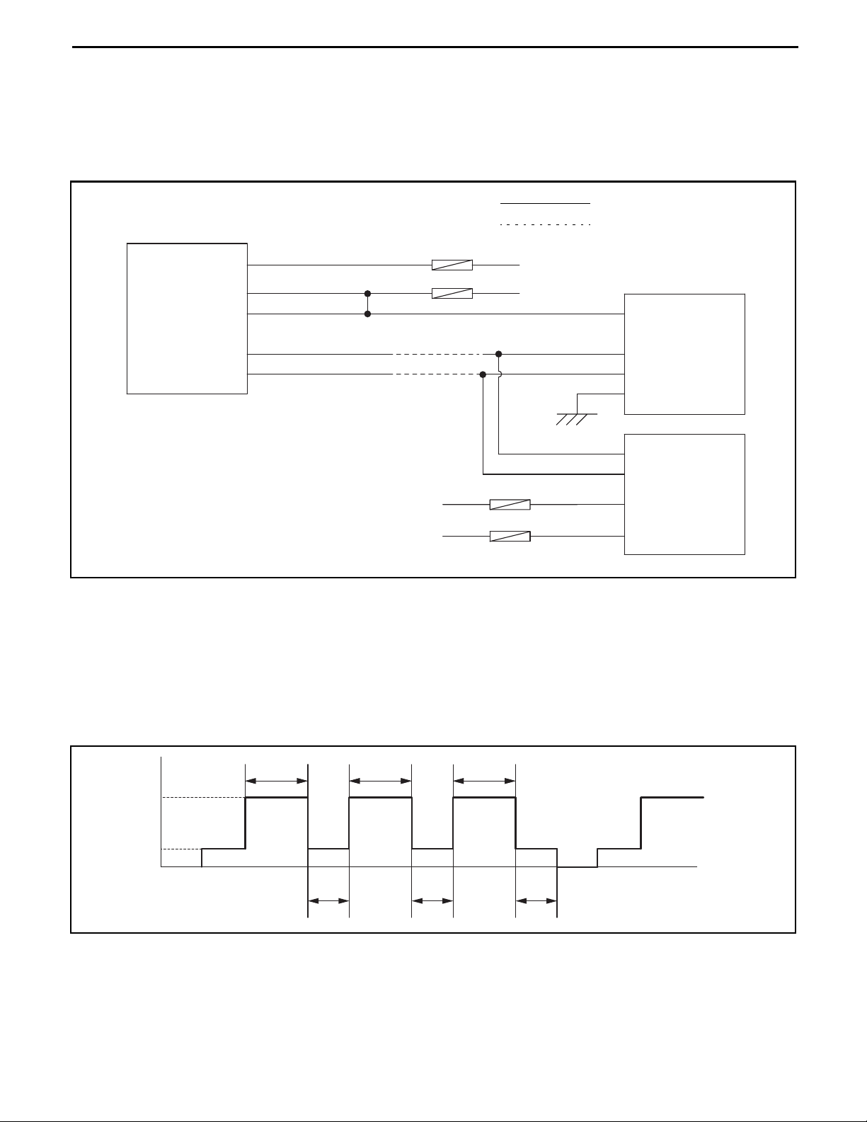
VIEWING RELATED PORTIONS
In the wiring diagrams for related portions, there are cases in which the parts are connected directly, and cases
where they are connected via a junction block or similar.
Refer below for how to identify wiring configuartions.
Example of a Related Portion
: Direct connection
A21
8 (BATT)
ECU-B
: Connection via a junction
ECU-IG
EFI
IGN
SAS/OPS
controller
1 (IG1)
2 (IG2)
A20
12 (CANH)
13 (CANL)
ERROR CONFIRMATION DRIVE MODE
c Turn the ignition key switch ON, start and completely warm up the engine.
d Fully depress the accelerator pedal for 3 to 5 minutes with the direction neutral.
e Release and leave the accelerator pedal (run the engine at idle) for 2 minutes.
f Repeat steps d and e 3 times.
g Turn the ignition key switch OFF (for 1 minute).
h Repeat steps c to g 3 times.
Q2
2 (IG)
5 (CANH)
6 (CANL)
3 (E1)
A36
28 (CAN+)
29 (CAN-)
3 (BATT)
9 (IGSW)
Multifunction
display
Engine
controller
Engine speed
NMR
Warmed up
Idle
IG
OFF
3 ~ 5 minutes 3 ~ 5 minutes 3 ~ 5 minutes
2 minutes 2 minutes 2 minutes
IG
OFF
time
19-1419-14
Electrical System Troubleshooting
Section 19
TROUBLESHOOTING BY ERROR CODE
z Error codes 01-1, 01-2 (Fuel feedback control abnormality) (Gasoline)
Related portion
C1
O2 sensor
Engine
controller
A35
20 (OX) 3 (OX)
20 (OX) 4
21 (E11) 4 (E1)
AC2
REC
7
TAB
Probable cause
c Intake system defect g Fuel system defect
d Exhaust system defect h Harness defect
e Sensor defect i Engine controller defect
f Ignition defect
Caution:
When another error code is present repair the related parts first before carrying out the following.
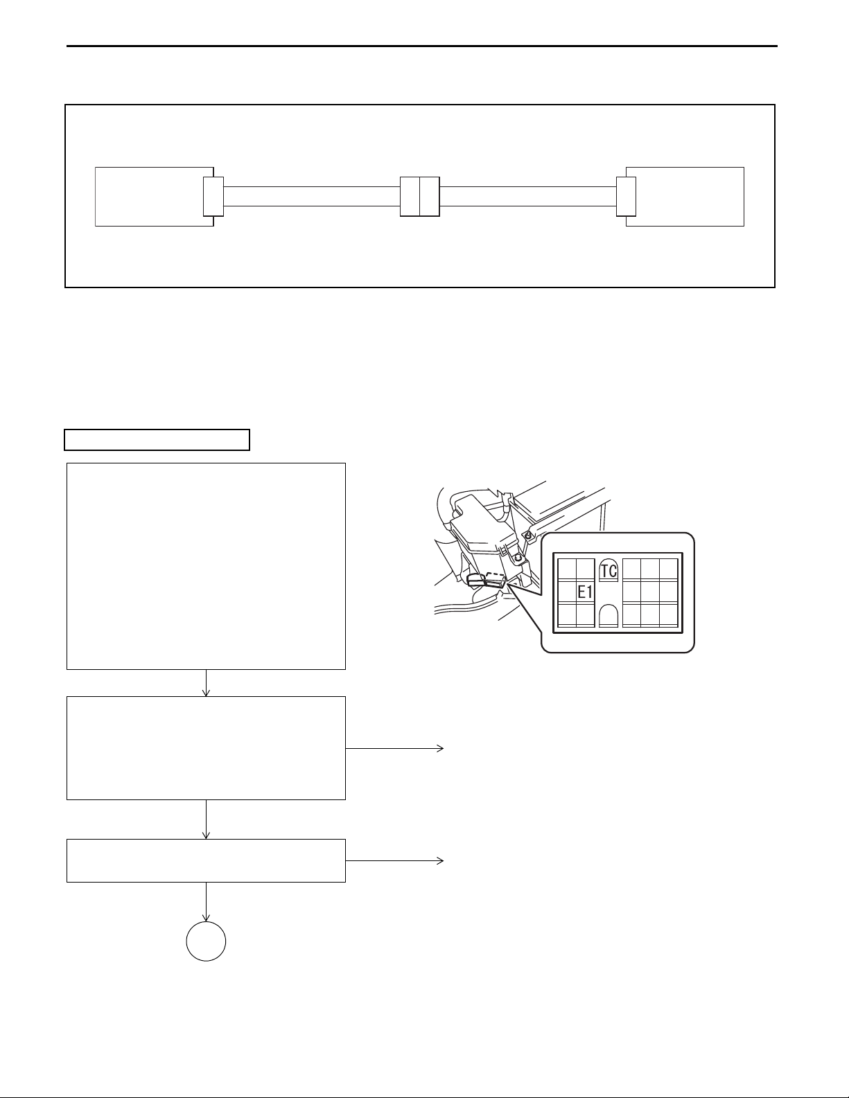
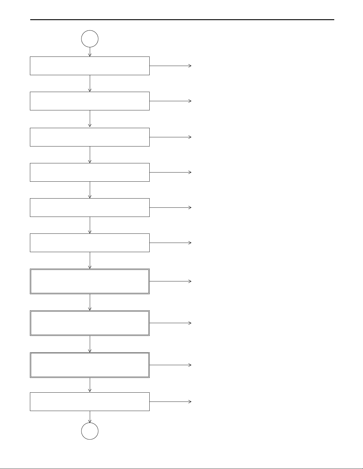
Error codes 01-1 and 01-2
Disconnect the battery negative terminal (for
more than 10 seconds). Check the connection
status of C1, disconnect C1 and perform a visual
and contact pressure inspection of the
connector. Short circuit the service connector TC
terminal with the E1 terminal, and after
connecting C1 and the battery negative terminal
(on a combination vehicle, switch the fuel
changeover switch to gasoline), turn the ignition
key switch ON (engine stopped), depress the
accelerator pedal 5 times within 30 seconds
(fully open to fully closed), then start the engine
and check that the error has been cleared.
Service connector
Disconnect the battery negative terminal,
disconnect TC terminal - E1 terminal, connect
the battery negative terminal, start the engine,
and check whether the error occurs after
performing error confirmation drive mode (see
19-13).
Error
Inspection 1:
Inspect the air intake
OK
A
No error
NG
Connector contact defect
Intake system defect
Intake system connection defect
19-15
Electrical System Troubleshooting
Section 19
A
Exhaust gas leakage inspection
OK
Inspection 3:
Fuel leakage inspection
OK
Fuel pressure inspection
OK
Inspection 5:
Spark plug individual inspection
OK
Inspection 6:
Injector individual inspection
OK
NGInspection 2:
NG
NGInspection 4:
NG
NG
Exhaust system defect
Exhaust system
Fuel system defect
Fuel system connection defect
Pressure regulator defect
Fuel filter defect
Fuel pump defect
Spark plug defect
Injector defect
Inspection 7:
Intake pipe pressure sensor voltage inspection
ANL.: I/O ENGINE CTRL 3/10
OK
Inspection 8:
Intake temperature sensor voltage inspection
ANL.: I/O ENGINE CTRL 3/10
OK
Inspection 9:
Coolant temperature sensor voltage inspection
ANL.: I/O ENGINE CTRL 3/10
OK
Harness continuity and short circuit inspection
OK
B
NG
Intake pipe pressure sensor defect
NG
Intake temperature sensor defect
NG
Coolant temperature sensor defect
NGInspection 10:
Harness defect
19-1619-16
Electrical System Troubleshooting
Section 19
B
Inspection 11:
O2 sensor voltage inspection
ANL.:I/O ENGINE CTRL 9/10
NG
Inspection 12:
2 sensor voltage inspection
O
ANL.:I/O ENGINE CTRL 9/10
OK
O2 sensor defect
OK
NG
Connector contact defect
Engine controller defect
Inspection 1:
Inspect for air suction.
Start the engine and check whether air is being sucked in from the engine oil level gauge, oil filler cap, or PCV
hose etc.
Standard: There is no air being sucked in.
Check if there is air being sucked in from the intake system parts and connections between the air cleaner and
the cylinder head.
Standard: There is no air being sucked in.
Inspection 2:
Inspect for exhaust gas leakage.
Start the engine and check if there is any exhaust gas leakage from the exhaust system parts and connections
between the cylinder head and the catalytic muffler.
Standard: There is no exhaust gas leakage.
Inspection 3:
Inspect for fuel leakage.
Start the engine and check if there is any fuel leakage from the fuel system parts and connections between the
fuel pump and the injectors.
Standard: There is no fuel leakage.
Inspection 4:
Inspect the fuel pressure.
For the fuel pressure inspection, refer to the repair manual for the 4Y engine.
Inspection 5:
Carry out a spark plug individual inspection.
For the spark plug individual inspection, refer to the repair manual for the 4Y engine.
Inspection 6:
Carry out an injector individual inspection.
For the individual injector inspection, refer to the repair manual for the 4Y engine.

Inspection 7:
Electrical System Troubleshooting
Section 19
Inspect the intake pipe pressure sensor voltage.
Ignition key switch ON, engine stopped
Intake pipe pressure sensor voltage (I/O monitor: PIM)
Standard:
PIM
3.6 ± 0.3 V (100 ± 10 kPa (1 ± 0.1 kgf/cm
Inspection 8:
Inspect the intake temperature sensor voltage.
Ignition key switch ON, engine stopped
Intake temperature sensor voltage (I/O monitor: THA)
Standard:
THA
0.55 ± 0.15 V (80 ± 10°C) (reference value)
2.4 ± 0.6 V (20 ± 10°C)
Inspection 9:
Inspect the coolant temperature sensor voltage.
Start the engine, warm up completely (coolant temperature gauge: at 5-6 bars)
Coolant temperature sensor voltage (I/O monitor: THW)
2
) [14 ± 1.4 psi])
19-17
Standard:
THW
0.55 ± 0.15 V (80 ± 10°C)
2.4 ± 0.6 V (20 ± 10°C) (reference value)
Inspection 10:
Inspect for continuity and short circuiting of the harness.
Ignition key switch OFF, disconnect battery negative terminal, disconnect A35 and C1.
Standard:
A35-20 ~ C1-3 Continuity
A35-21 ~ C1-4 Continuity
A35-20 ~ Frame No continuity
Inspection 11:
Inspect the O
2 sensor output.
Connect A35 and C1, start the engine, warm up completely, set direction in neutral, fully open the accelerator
pedal
2 sensor voltage (I/O monitor: OX)
O
Standard:
OX 0.4 V or less and 0.5 V or more alternately output
Inspection 12:
Inspect the O
2 sensor output.
Disconnect C1, connect A35, start the engine, warm up completely, set direction in neutral, fully open the
accelerator pedal
2 sensor voltage (I/O monitor: OX)
O
Standard:
OX 0.2 V or less
19-1819-18
Electrical System Troubleshooting
Section 19
z Error codes 01-3, 01-4 (Fuel feedback control abnormality) (LPG/CNG)
Related portion
Engine
controller
A35
20 (OX) 4
20 (OX) 3 (OX)
21 (E11) 4 (E1)
AC2
REC
7
TAB
C1
O
2 sensor
Probable cause
c Intake system defect g Fuel system defect
d Exhaust system defect h Harness defect
e Sensor defect i Engine controller defect
f Ignition defect
Caution:
When another error code is occuring, repair the related parts first before carrying out the following.
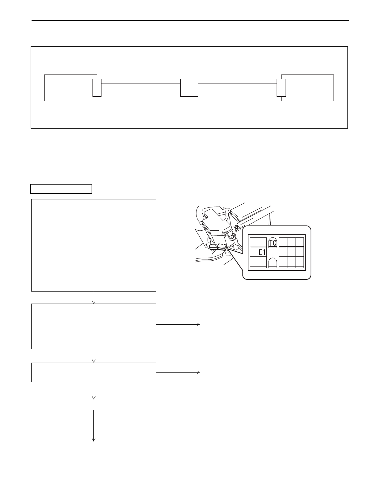
Error codes 01-3 and 01-4
Disconnect the battery negative terminal (for
more than 10 seconds). Check the connection
status of C1, disconnect C1 and perform a visual
and contact pressure inspection of the
connector. Short circuit the service connector TC
terminal with the E1 terminal, and after
connecting C1 and the battery negative terminal
(on a combination vehicle, switch the fuel
changeover switch to gasoline), turn the ignition
key switch ON (engine stopped), depress the
accelerator pedal 5 times within 30 seconds
(fully open to fully closed), then start the engine
and check that the error has been cleared.
Service connector
Disconnect the battery negative terminal,
disconnect TC terminal - E1 terminal, connect
the battery negative terminal, start the engine,
and check whether the error occurs after
performing error confirmation drive mode (see
19-13).
Error
Inspection 1:
Inspect the air intake
OK
A
No error
NG
Connector contact defect
Intake system defect
Intake system connection defect
19-19
Electrical System Troubleshooting
Section 19
A
Exhaust gas leakage inspection
OK
Fuel leakage inspection
OK
Inspection 4:
Regulator primary pressure inspection
OK
Inspection 5:
Spark plug individual inspection
OK
Inspection 6:
Injector individual inspection
OK
NGInspection 2:
NGInspection 3:
NG
NG
NG
Exhaust system defect
Exhaust system connection defect
Fuel system defect
Fuel system connection defect
Regulator defect
Spark plug defect
Injector defect
Air-fuel ratio motor individual inspection
OK
Inspection 8:
Intake pipe pressure sensor voltage inspection
ANL.: I/O ENGINE CTRL 3/10
OK
Inspection 9:
Intake temperature sensor voltage inspection
ANL.: I/O ENGINE CTRL 3/10
OK
Inspection 10:
Water temperature sensor voltage inspection
ANL.: I/O ENGINE CTRL 3/10
OK
Harness continuity and short circuit inspection
NGInspection 7:
Air-fuel ratio motor defect
NG
Intake pipe pressure sensor defect
NG
Intake temperature sensor defect
NG
Water temperature sensor defect
NGInspection 11:
Harness defect
OK
B

19-2019-20
Electrical System Troubleshooting
Section 19
B
Inspection 12:
O2 sensor voltage inspection
ANL.:I/O ENGINE CTRL 9/10
NG
Inspection 13:
2 sensor voltage inspection
O
ANL.:I/O ENGINE CTRL 9/10
OK
O2 sensor defect
OK
NG
Connector contact defect
Engine controller defect
Inspection 1:
Inspect for air suction.
Start the engine and check whether air is being sucked in from the engine oil level gauge, oil filler cap, or PCV
hose etc.
Standard: There is no air being sucked in.
Check if there is air being sucked in from the intake system parts and connections between the air cleaner and
the regulator.
Standard: There is no air being sucked in.
Check if there is air being sucked in from the intake system parts and connections among the air cleaner hose,
the resonator, and the regulator.
Standard: There is no air being sucked in.
Inspection 2:
Inspect for exhaust gas leakage.
Start the engine and check if there is any exhaust gas leakage from the exhaust system parts and connections
between the cylinder head and the catalytic muffler.
Standard: There is no exhaust gas leakage.
Inspection 3:
Inspect for fuel leakage.
Start the engine and check if there is any fuel leakage from the fuel system parts and connections between the
fuel tank and the regulator.
Standard: There is no fuel leakage.
Check if there is fuel leakage from the fuel system parts and connections between the regulator and the LPG
adapter.
Standard: There is no fuel leakage.
Check if there is fuel leakage from the fuel system parts and connections between the regulator and the injector.
Standard: There is no fuel leakage.
Inspection 4:
Inspect the regulator primary pressure.
For the regulator primary pressure inspection, refer to the LPG repair manual.

Inspection 5:
Electrical System Troubleshooting
Section 19
Carry out a spark plug individual inspection.
For the spark plug individual inspection, refer to the repair manual for the 4Y engine.
Inspection 6:
Carry out an injector individual inspection.
For the individual injector inspection, refer to the repair manual for the 4Y engine.
Inspection 7:
Carry out an individual inspection of the air-fuel ratio motor.
For the individual air-fuel ratio motor inspection, refer to the LPG repair manual.
Inspection 8:
Inspect the intake pipe pressure sensor voltage.
Ignition key switch ON, engine stopped
Intake pipe pressure sensor voltage (I/O monitor: PIM)
Standard:
PIM
3.6 ± 0.3 V (100 ± 10 kPa (1 ± 0.1 kgf/cm
2
) [14 ± 1.4 psi])
19-21
Inspection 9:
Inspect the intake temperature sensor voltage.
Ignition key switch ON, engine stopped
Intake temperature sensor voltage (I/O monitor: THA)
Standard:
THA
0.55 ± 0.15 V (80 ± 10°C) (reference value)
2.4 ± 0.6 V (20 ± 10°C)
Inspection 10:
Inspect the coolant temperature sensor voltage.
Start the engine, warm up completely (coolant temperature gauge: 5-6 bars)
Coolant temperature sensor voltage (I/O monitor: THW)
Standard:
THW
0.55 ± 0.15 V (80 ± 10°C)
2.4 ± 0.6 V (20 ± 10°C) (reference value)
Inspection 11:
Inspect for continuity and short circuiting of the harness.
Ignition key switch OFF, disconnect A35 and C1
Standard:
A35-20 ~ C1-3 Continuity
A35-21 ~ C1-4 Continuity
A35-20 ~ Frame No continuity

19-2219-22
Electrical System Troubleshooting
Section 19
Inspection 12:
Inspect the O
2 sensor output.
Start the engine, warm up completely, put the direction in neutral, fully open the accelerator pedal
2 sensor voltage (I/O monitor: OX)
O
Standard:
OX 0.4 V or less and 0.5 V or more alternately output
Inspection 13:
Inspect the O
2 sensor output.
Start the engine, warm up completely, put the direction in neutral, fully open the accelerator pedal
2 sensor voltage (I/O monitor: OX)
O
Standard:
OX 0.2 V or less
z Error code 01-5 (O2 sensor open abnormality)
Electrical System Troubleshooting
Section 19
Related portion
19-23
Engine
controller
A35
20 (OX) 4
20 (OX) 3 (OX)
21 (E11) 4 (E1)
AC2
REC
7
TAB
C1
O
2 sensor
Probable cause
c O2 Sensor defect
d Harness defect
e Engine controller defect
Caution:
When another error code is present, repair the related parts first before carrying out the following.
Error code 01-5
Disconnect the battery negative terminal (for
more than 10 seconds). Check the connection
status of C1, disconnect C1 and perform a visual
and contact pressure inspection of the
connector. Short circuit the service connector TC
terminal with the E1 terminal, and after
connecting C1 and the battery negative terminal
(on a combination vehicle, switch the fuel
changeover switch to gasoline), turn the ignition
key switch ON (engine stopped), depress the
accelerator pedal 5 times within 30 seconds
(fully open to fully closed), then start the engine
and check that the error has been cleared.
Service connector
Disconnect the battery negative terminal,
disconnect TC terminal - E1 terminal, connect
the battery negative terminal, start the engine,
and check whether the error occurs after
performing error confirmation drive mode (see
19-13).
Error
Harness continuity and short circuit inspection
OK
2 sensor defect
O
If the error occurs even
after replacing the O
sensor
Engine controller defect
2
No error
NGInspection 1:
Connector contact defect
Harness defect

19-2419-24
Electrical System Troubleshooting
Section 19
Inspection 1:
Inspect for continuity and short circuiting of the harness.
Ignition key switch OFF, disconnect A35 and C1
Standard:
A35-20 ~ C1-3 Continuity
A35-21 ~ C1-4 Continuity
A35-20 ~ Frame No continuity
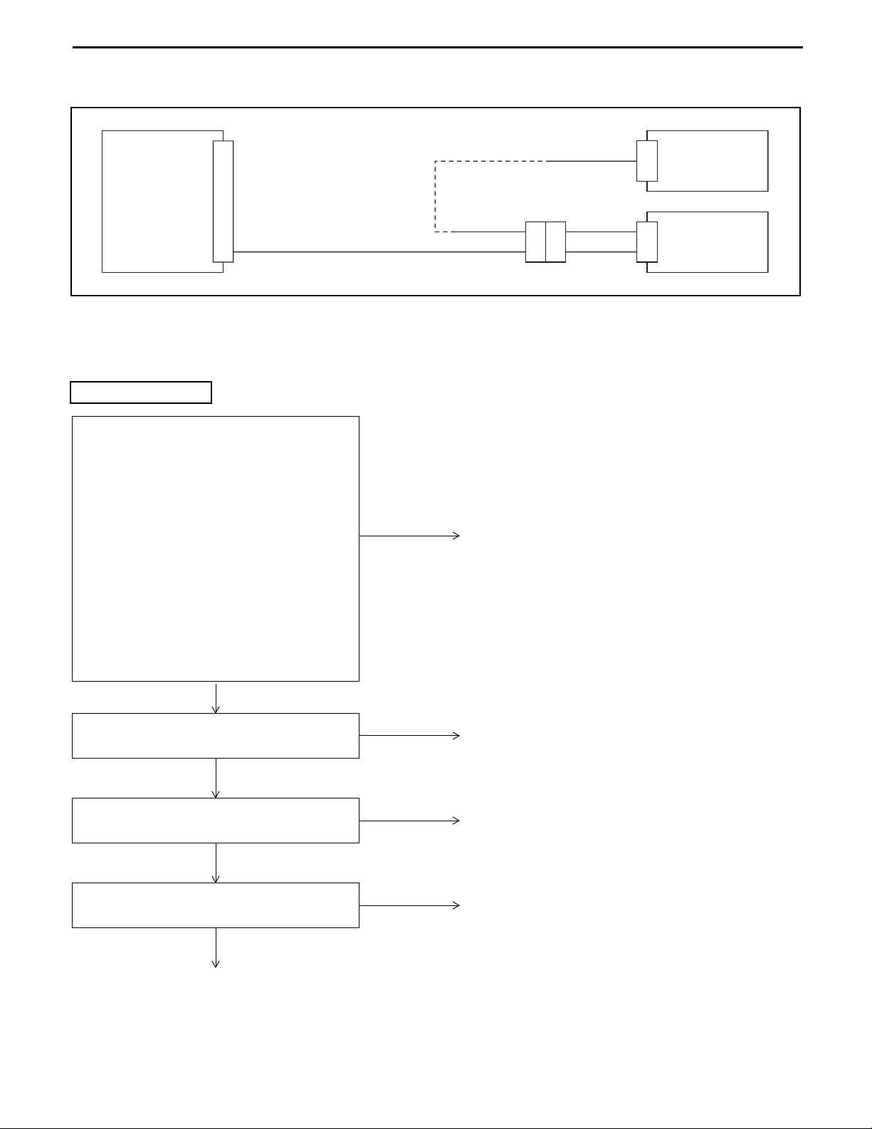
z Error code 01-6 (O2 sensor heater open abnormality)
Electrical System Troubleshooting
Section 19
Related portion
19-25
A35
Engine
controller
6 (HT)
Probable cause
c O2 Sensor defect
d Harness defect
e Engine controller defect
Error code 01-6
Disconnect the battery negative terminal (for
more than 10 seconds), after inspecting and
correcting disconnection and water entry of C1,
AC2, reconnect all connectors and battery
negative terminal, turn the ignition key switch
ON (start the engine), and check whether or not
there is an error.
c Turn the ignition key switch ON.
(Start and run the engine for more than 10
seconds.)
d Turn the ignition key switch OFF for more
than10 seconds.
e Turn the ignition key switch ON.
(Start and run the engine for more than 10
seconds.)
f Check for errors.
No error
AC2
9
1
TAB
REC
Connector contact defect
R/B EFI Main relay
main relay
C1
2
1
EFI
2
O
sensor
Error
2 sensor individual inspection
O
OK
Inspection 2:
O
2 sensor heater power voltage inspection
OK
Inspection 3:
Harness continuity and short circuit inspection
OK
Engine controller defect
NGInspection 1:
O2 sensor defect
NG
Harness defect
NG
Harness defect
19-2619-26
Electrical System Troubleshooting
Section 19
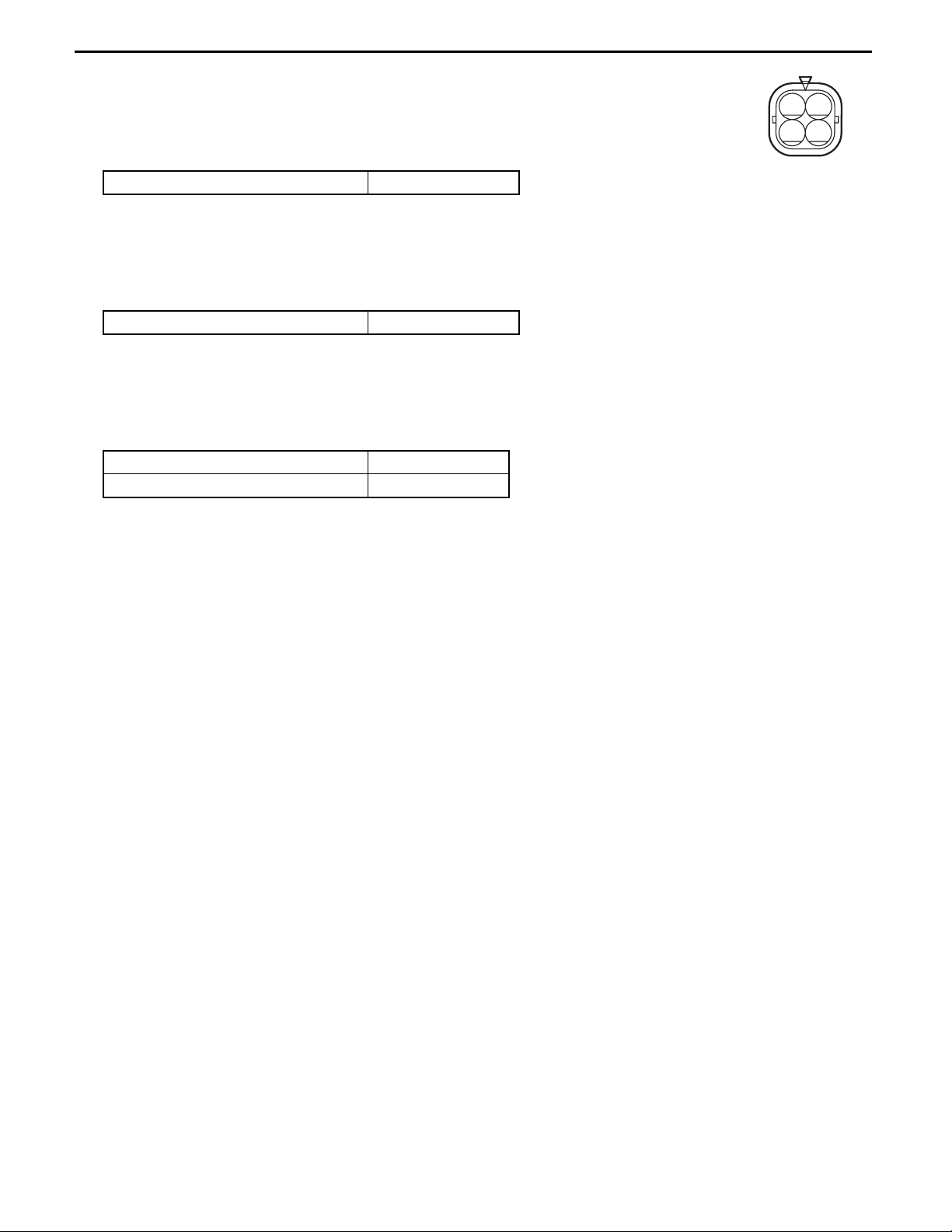
Inspection 1:
Carry out O
2 sensor individual inspection.
Ignition key switch OFF, disconnect C1, connect A35
Standard: (Sensor side)
C1-2 ~ C1-1 13 ~ 16 Ω (20°C)
Inspection 2:
Carry out O
2 sensor heater power voltage inspection.
Ignition key switch OFF, diconnect C1, connect A35, start engine
Standard:
C1-2 ~ Frame 8 ~ 16 V
Inspection 3:
Inspect for continuity and short circuiting of the harness.
Ignition key switch OFF, disconnect A35 and C1
Standard:
A35-6 ~ C1-1 Continuity
A35-6 ~ Frame No continuity
12
34
C1
 Loading...