


4 Runner 1987
ARTICLE BEGINNING
APPLICATION
TRANSMISSION APPLICATION
Vehicle Application Transmission Model
1985-87 4WD Pickup, 4Runner G52
1985-89 Van (2WD & 4WD) G53
DESCRIPTION
The Toyota G52 and G53 5-speed transmissions are fully synchronized units. All forward gears are
helical cut and in constant mesh. Reverse gear is spur cut. Reverse and 5th gears are mounted on
the rear side of the intermediate plate. The floor shifter actuates a single control rod in the transfer
adapter which operates 3 shift rails mounted in the intermediate plate and the main case.
Page
1
of
19
OVERHAUL
-
G52 & G53 5
-
SPEED
-
1987 Toyota 4Runner
10/5/2009
http://www.ondemand5.com/mric/common/asp/printart.aspx
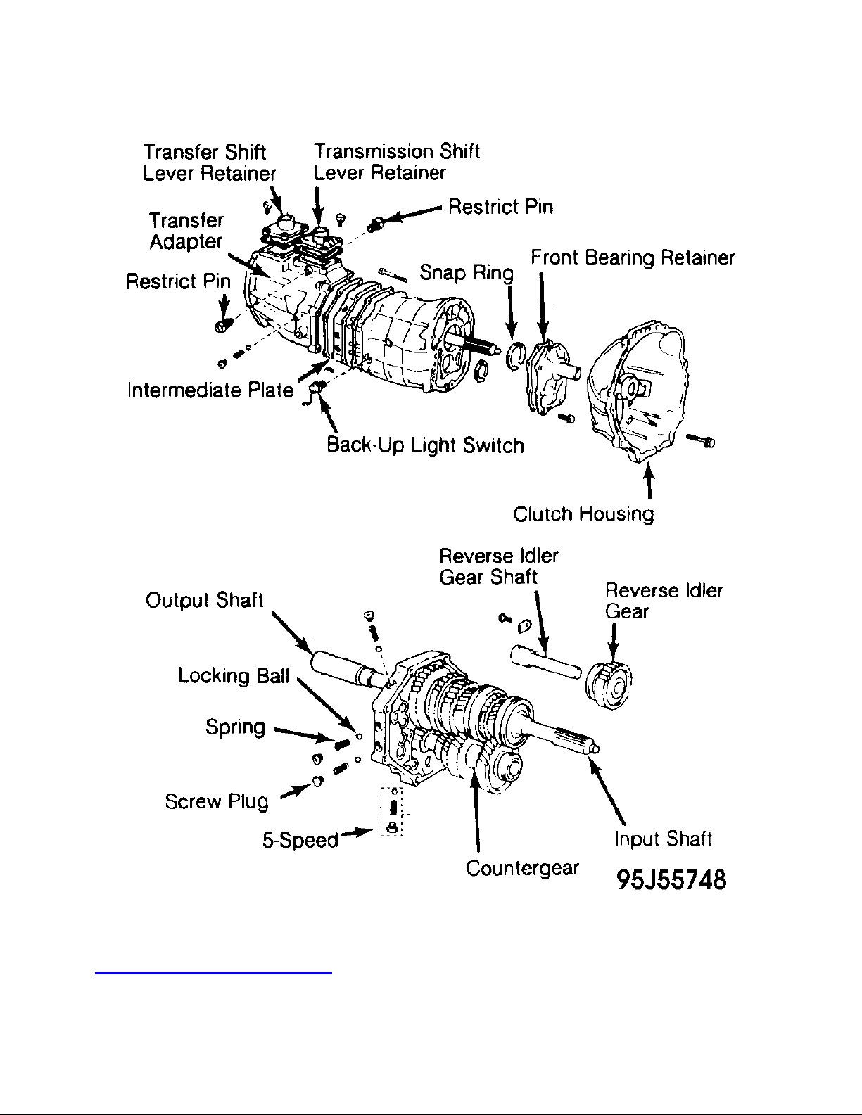
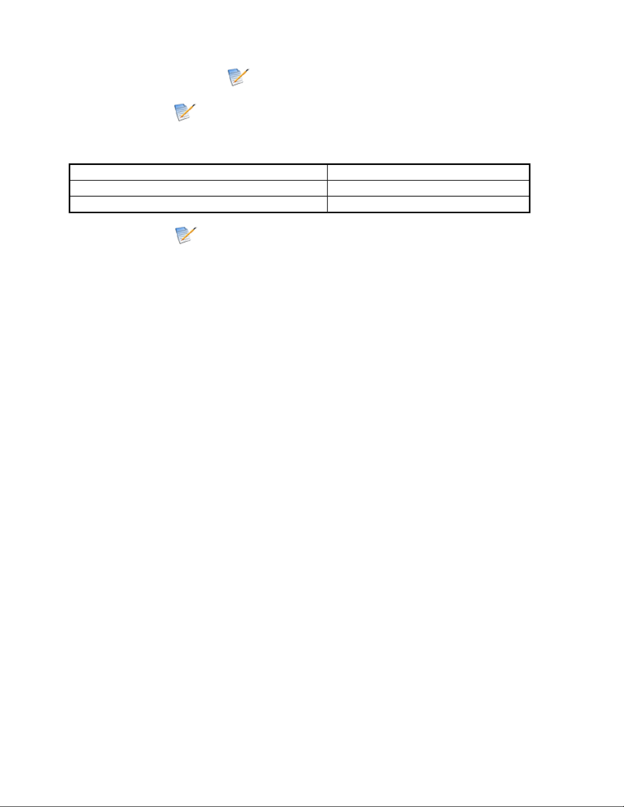
Fig. 1: Toyota G52 Transmission
Courtesy of TOYOTA MOTOR SALES, U.S.A., INC.
Page
2
of
19
OVERHAUL
-
G52 & G53 5
-
SPEED
-
1987 Toyota 4Runner
10/5/2009
http://www.ondemand5.com/mric/common/asp/printart.aspx

LUBRICATION & ADJUSTMENTS
See appropriate TRANSMISSION SERVICING - M/T article in the MANUAL TRANS
SERVICE section.
For 1985 Toyota Vehicles, see TRANSMISSION SERVICING - M/T •
For 1986 Toyota Vehicles, see TRANSMISSION SERVICING - M/T •
For 1987 Toyota Vehicles, see TRANSMISSION SERVICING - M/T •
For 1988 Toyota Vehicles, see TRANSMISSION SERVICING - M/T •
For 1989 Toyota Vehicles, see TRANSMISSION SERVICING - M/T •
TROUBLE SHOOTING
See TROUBLE SHOOTING - BASIC PROCEDURES in the GENERAL TROUBLE
SHOOTING section.
REMOVAL & INSTALLATION
See appropriate TRANSMISSION REMOVAL & INSTALLATION - M/T article in the
MANUAL TRANS SERVICE section.
For 1985-86 Pickup & 4Runner, see TRANSMISSION REMOVAL & INSTALLATION
- M/T
•
For 1987 Pickup & 4Runner, see TRANSMISSION REMOVAL & INSTALLATION -
M/T
•
For 1985 Van, see TRANSMISSION REMOVAL & INSTALLATION - M/T •
For 1986 Van, see TRANSMISSION REMOVAL & INSTALLATION - M/T •
For 1987 Van, see TRANSMISSION REMOVAL & INSTALLATION - M/T •
TRANSMISSION DISASSEMBLY
G52 TRANSFER ADAPTER
Remove back-up light switch, shift lever retainer and restrict pins. Remove 9 clutch housing
bolts. Using plastic hammer, remove clutch housing from transmission case. See Fig. 1 and
Fig. 2 .
1.
Using Torx head socket, remove screw plug from transfer adapter. Remove spring and ball.
Remove Allen head plug from rear face of transfer adapter. Remove shift lever housing set
bolt and lock washer.
2.
Remove shift lever shaft and housing. Remove 8 transfer adapter bolts. Using plastic
hammer, remove transfer adapter. Leave gasket attached to intermediate plate.
3.
Page
3
of
19
OVERHAUL
-
G52 & G53 5
-
SPEED
-
1987 Toyota 4Runner
10/5/2009
http://www.ondemand5.com/mric/common/asp/printart.aspx
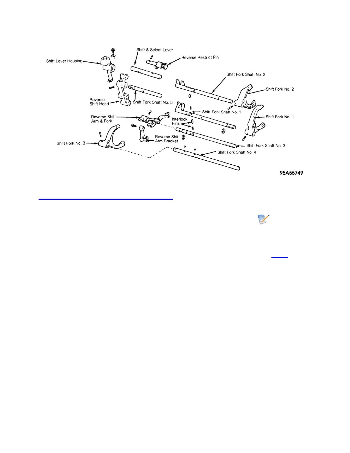
Fig. 2: Exploded View of Shift Forks & Shafts
Courtesy of TOYOTA MOTOR SALES, U.S.A., INC.
G53 EXTENSION HOUSING (2WD) OR TRANSFER ADAPTER (4WD)
Remove release fork and bearing. Remove back-up light switch and speedometer driven
gear. Remove clutch housing from transmission.
1.
Remove shift lever housing assembly. Remove 8 extension housing bolts. See Fig. 3 . Using
plastic hammer, tap extension housing and remove.
2.
Remove shift lever housing and shift and select lever. Leave gasket attached to intermediate
plate.
3.
Page
4
of
19
OVERHAUL
-
G52 & G53 5
-
SPEED
-
1987 Toyota 4Runner
10/5/2009
http://www.ondemand5.com/mric/common/asp/printart.aspx
Fig. 3: G53 Case & Shifter Fork Assemblies
Courtesy of TOYOTA MOTOR SALES, U.S.A., INC.
Page
5
of
19
OVERHAUL
-
G52 & G53 5
-
SPEED
-
1987 Toyota 4Runner
10/5/2009
http://www.ondemand5.com/mric/common/asp/printart.aspx

INTERMEDIATE PLATE
G52 Shift Fork Shafts
Remove front bearing retainer and 2 bearing snap rings from front of transmission case.
Using plastic hammer, carefully separate transmission case from intermediate plate.
1.
Install 2 long clutch housing bolts, plate washers and nuts in 2 bottom holes of intermediate
plate. Install plate washers in reverse of normal. Mount intermediate plate in vise, with vise
jaw pressure on bolts. Increase or decrease plate washers so bolt tip and front tip surface of
nut are aligned and mounted evenly.
2.
Using Torx head socket, remove 4 screw plugs, locking balls and springs from intermediate
plate. Drive out 5 shift fork-to-shift rail pins. Remove 2 shift rail "E" rings.
3.
Pull out shift fork shaft No. 4 from intermediate plate catching 2 interlock balls and pin. If
they do not fall out, remove with magnet. Remove shift fork shaft No. 4 and shift fork No. 3.
4.
Pull out shift fork shaft No. 5 from intermediate plate, and remove with reverse shift head.
Pull out shift fork shaft No. 3 from intermediate plate catching 2 interlock pins as they fall
out. If they do not come out, remove with magnet.
5.
Remove shift fork shaft No. 1 and interlock pin from intermediate plate catching interlock
pin as it falls out. If it does not come out, remove with magnet. Pull out shift fork shaft No. 2
and remove shift forks No. 2 and No. 1.
6.
G53 Shift Fork Shafts
Remove front bearing retainer and 2 snap rings. Using plastic hammer, carefully tap
transmission case and separate from intermediate plate.
1.
Install 2 clutch bolts, washers and nuts in 2 bottom holes of intermediate plate. Increase or
decrease plate washers so bolt tip and front surface of nut are aligned. Mount intermediate
plate in vise with pressure on nuts and bolts, NOT intermediate plate.
2.
Using Torx socket, remove 4 plugs. Remove 4 springs and balls, catching them by hand as
they fall out. If they do not fall out, use magnet to remove. Drive out 4 pins. Remove 3 "E"
clips and No. 1 shift fork bolt. Pull out shift fork shaft No. 3 from intermediate plate.
3.
Remove shift fork and shaft No. 3. Remove locking ball and reverse shift head. Pull out shift
fork shaft No. 4 from intermediate plate, catching pins as they fall out. If they do not fall out,
remove with magnet.
4.
Remove shift fork shaft No. 4. Remove shift fork shaft No. 2 from intermediate plate. Catch
pin by hand when it falls from hole. If it does not fall out, remove with magnet.
5.
Remove shift fork shaft No. 2 and shift fork No. 2. Pull out shift fork shaft No. 1 and remove
shift fork No. 2, No. 1 and 1st and 2nd shift head.
6.
Input, Output & Countershafts
Remove reverse idler gear shaft stopper. Remove reverse idler gear and shaft. Remove
reverse shift arm from reverse shift arm bracket. Measure countershaft 5th gear thrust
clearance. See Fig. 4 .
1.
COUNTERSHAFT 5TH GEAR THRUST CLEARANCE
Page
6
of
19
OVERHAUL
-
G52 & G53 5
-
SPEED
-
1987 Toyota 4Runner
10/5/2009
http://www.ondemand5.com/mric/common/asp/printart.aspx
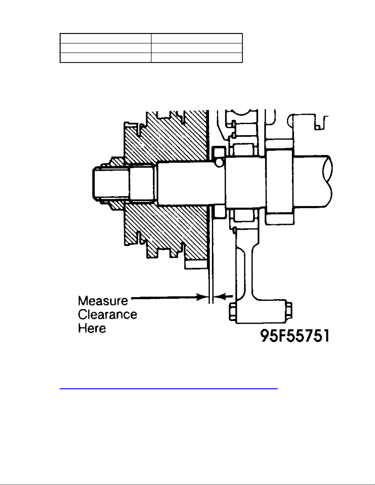
Application In. (mm)
Standard .0039-.0118 (.10-.30)
Maximum .0118 (.30)
Fig. 4: Measuring Point For Countershaft 5th Gear Thrust Clearance
Courtesy of TOYOTA MOTOR SALES, U.S.A., INC.
Loosen staked part of lock nut on gear spline piece No. 5. Remove lock nut. Using Puller
(09213-27010), remove gear spline piece No. 5, synchro ring, needle roller bearing and
counter 5th gear. Remove spacer and ball.
2
.
Remove 2 bolts and reverse shift
arm bracket. Using Torx head socket, remove 4 rear
bearing retainer bolts.
Remove rear bearing snap ring.
3
.
Page
7
of
19
OVERHAUL
-
G52 & G53 5
-
SPEED
-
1987 Toyota 4Runner
10/5/2009
http://www.ondemand5.com/mric/common/asp/printart.aspx
Remove output shaft, countershaft and input shaft as a unit from intermediate plate by
pulling on countergear and tapping intermediate plate with plastic hammer. Remove input
shaft and needle roller bearings from output shaft. Remove countershaft rear bearing from
intermediate plate using Driver (09608-12010). Remove sleeve from output shaft using
Puller (09950-20016).
4.
COMPONENT DISASSEMBLY & REASSEMBLY
OUTPUT SHAFT
Disassembly
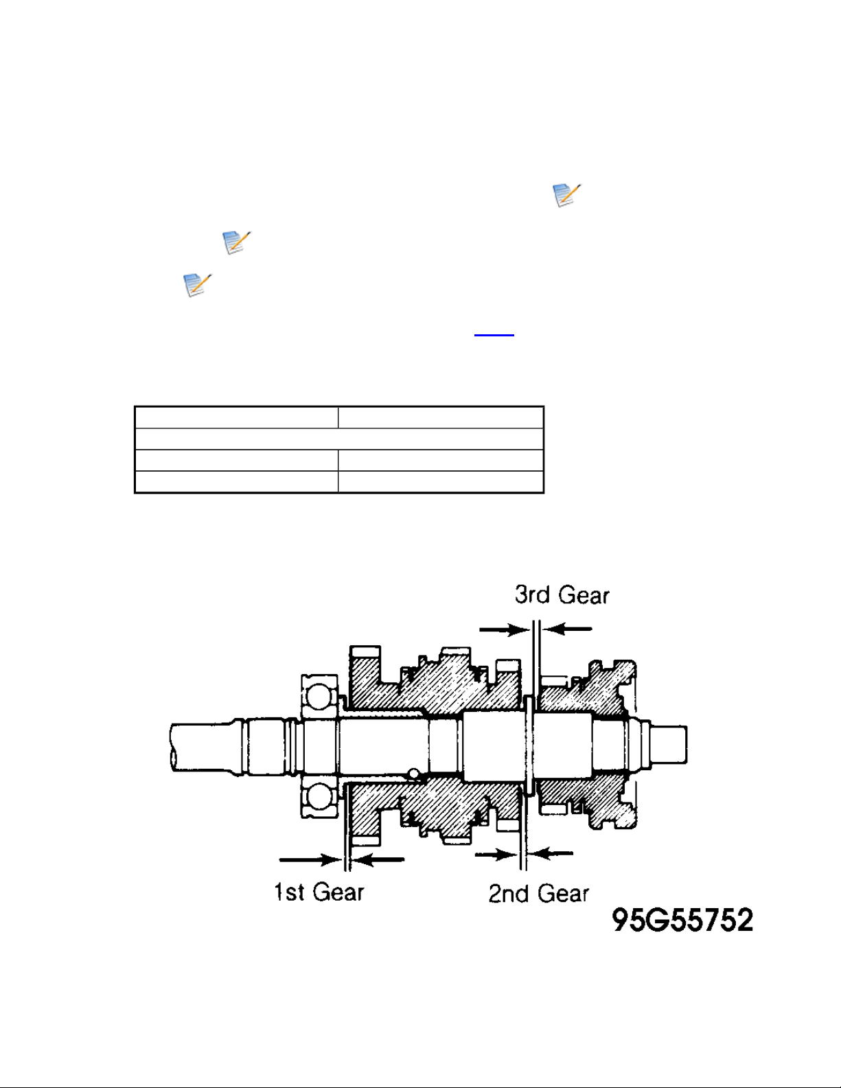
Measure end play of each gear on output shaft. See Fig. 5 . Remove snap ring and press 5th
gear, rear bearing, 1st gear and inner race from output shaft. Remove needle roller bearing.
1.
OUTPUT SHAFT GEAR THRUST CLEARANCES
Application In. (mm)
1st, 2nd & 3rd Gear
Standard .0039-.0098 (.10-.25)
Maximum .0098 (.25)
Page
8
of
19
OVERHAUL
-
G52 & G53 5
-
SPEED
-
1987 Toyota 4Runner
10/5/2009
http://www.ondemand5.com/mric/common/asp/printart.aspx

Fig. 5: Measuring Output Shaft Gear Thrust Clearances
Courtesy of TOYOTA MOTOR SALES, U.S.A., INC.
Remove synchro ring. Remove locking ball using magnet. Press hub sleeve No. 1, synchro
ring and 2nd gear off output shaft. Remove needle roller bearing.
2.
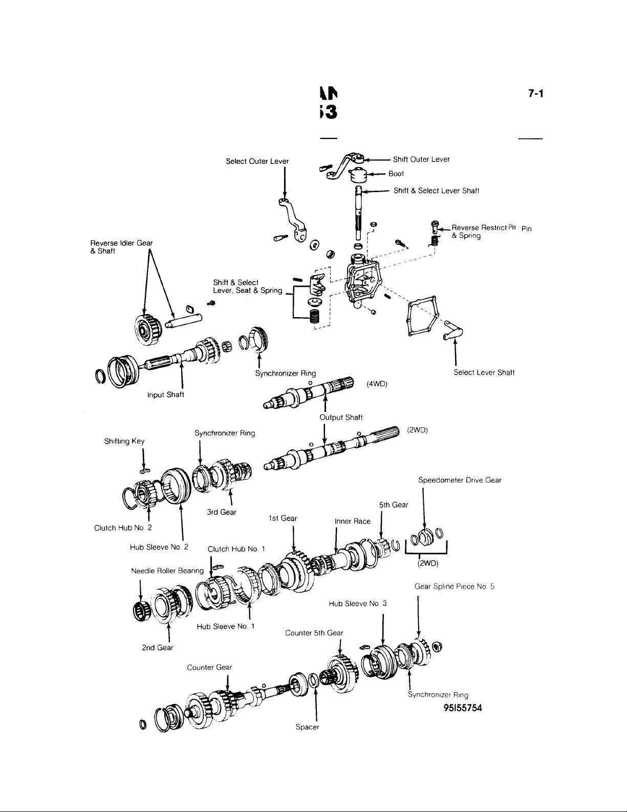
Remove snap ring and press hub sleeve No. 2, synchro ring and 3rd gear off output shaft.
See Fig. 6 or Fig. 7 . Remove needle roller bearing.
3.
Page
9
of
19
OVERHAUL
-
G52 & G53 5
-
SPEED
-
1987 Toyota 4Runner
10/5/2009
http://www.ondemand5.com/mric/common/asp/printart.aspx
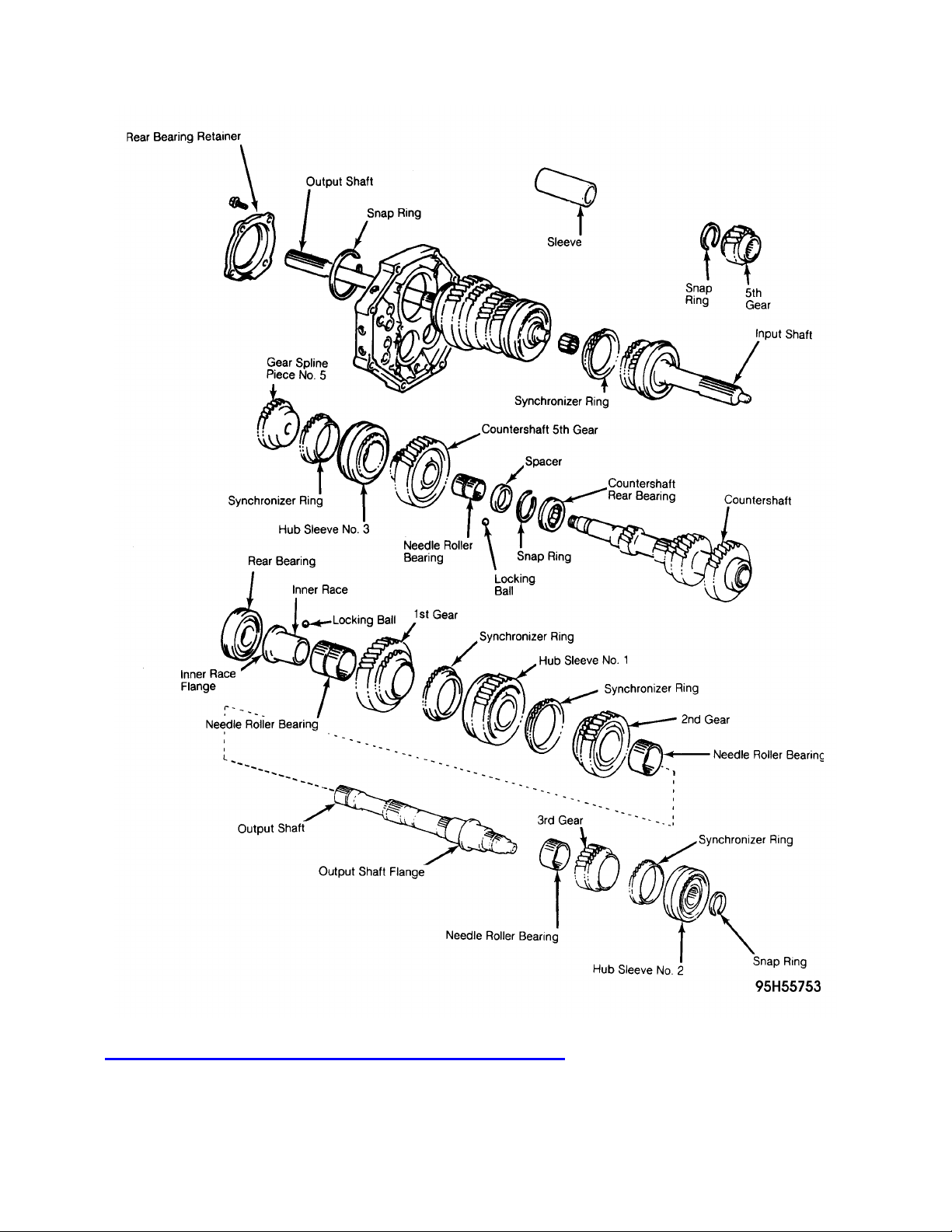
Fig. 6: Exploded View of Toyota G52 Transmission Gears
Courtesy of TOYOTA MOTOR SALES, U.S.A., INC.
Page
10
of
19
OVERHAUL
-
G52 & G53 5
-
SPEED
-
1987 Toyota 4Runner
10/5/2009
http://www.ondemand5.com/mric/common/asp/printart.aspx
Page
11
of
19
OVERHAUL
-
G52 & G53 5
-
SPEED
-
1987 Toyota 4Runner
10/5/2009
http://www.ondemand5.com/mric/common/asp/printart.aspx

Fig. 7: Exploded View of Toyota G53 Transmission Gears
Courtesy of TOYOTA MOTOR SALES, U.S.A., INC.
Cleaning & Inspection
Clean all parts in solvent. Inspect output shaft and inner race for wear or damage. Using
caliper, measure output shaft flange thickness and inner race flange thickness. See OUTPUT
SHAFT SPECIFICATION table.
1.
Using micrometer, measure outer diameter of output shaft journal surface and outer diameter
of inner race. Mount output shaft between 2 "V" blocks and measure shaft runout at center
of shaft.
2.
OUTPUT SHAFT SPECIFICATIONS
Application In. (mm)
Output Shaft Flange
Minimum Thickness .1890 (4.80)
Inner Race Flange
Minimum Thickness .1571 (3.99)
Inner Race Outer Diameter
Minimum Diameter 1.5348 (38.985)
Output Shaft Journal (Outer Diameter)
Minimum Diameter
2nd Gear 1.4954 (37.984)
3rd Gear 1.3773 (34.984)
Maximum Runout .002 (.05)
Using dial indicator, measure oil clearance between 1st gear and inner race with needle
roller bearing installed. See GEAR-TO-SHAFT OIL CLEARANCE SPECIFICATIONS
table. If clearance exceeds limit, replace gear, inner race or needle roller bearing.
3.
Measure oil clearance between output shaft and 2nd gear between shaft and 3rd gear.
Measure oil clearance between countershaft and 5th gear. If clearance exceeds limit, replace
gear, needle roller bearing or shaft.
4.
GEAR-TO-SHAFT OIL CLEARANCE SPECIFICATIONS
Application Standard In.
(mm)
Maximum In.
(mm)
1st Gear-to-Inner Race .00035-.00126 .00126
(.009.-032) (.032)
2nd Gear-to-Shaft .00035-.00130 .00130
(.009-.033) (.033)
3rd Gear-to-Shaft .00035-.00130 .00130
(.009-.033) (.033)
5th Gear-to-Countershaft .00035-.00126 .00126
(.009-.032) (.032)
Page
12
of
19
OVERHAUL
-
G52 & G53 5
-
SPEED
-
1987 Toyota 4Runner
10/5/2009
http://www.ondemand5.com/mric/common/asp/printart.aspx
Check all synchro rings for wear or damage. Turn ring and push in to check braking action.
Measure clearance between synchro ring back and gear spline end. See SYNCHRO RING
CLEARANCE SPECIFICATIONS table.
5.
SYNCHRO RING CLEARANCE SPECIFICATIONS
Application In. (mm)
Standard .039-.079 (1.0-2.0)
Maximum .031 (.80)
Measure clearance between shift forks and hub sleeves. Maximum clearance is .039" (1.0
mm).
6.
Reassembly
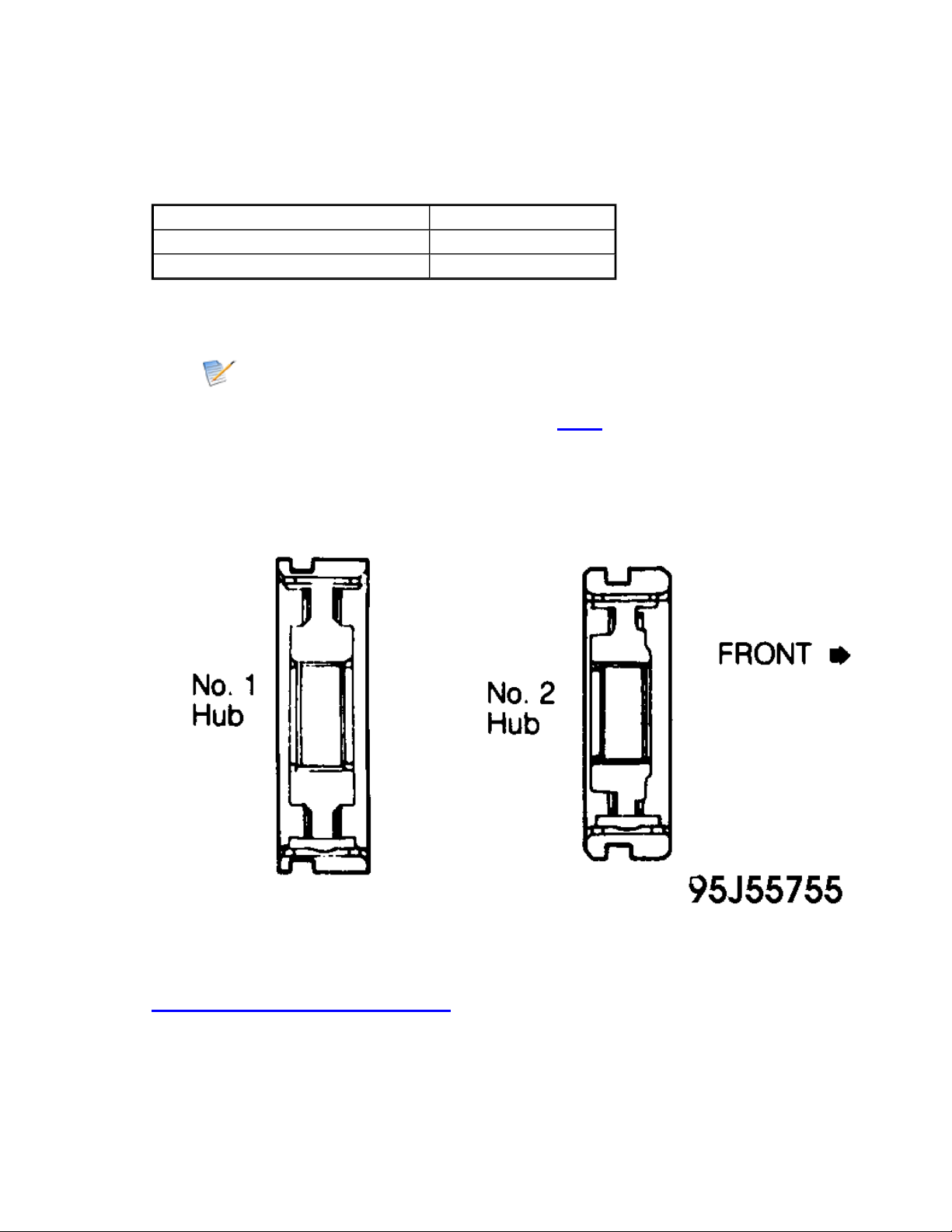
Install clutch hub and shifting keys in hub sleeve. See Fig. 8 . Install shifting key springs
under shifting keys. Install key springs so end gaps are not in line.
1.
Fig. 8: Sectional View of Clutch Hubs
Courtesy of TOYOTA MOTOR
SALES, U.S.A., INC.
Apply gear oil
to shaft and needle roller bearing. Place synchro ring on gear and align ring
slots with shifting keys. Install needle roller bearing in 3rd gear.
2
.
Page
13
of
19
OVERHAUL
-
G52 & G53 5
-
SPEED
-
1987 Toyota 4Runner
10/5/2009
http://www.ondemand5.com/mric/common/asp/printart.aspx
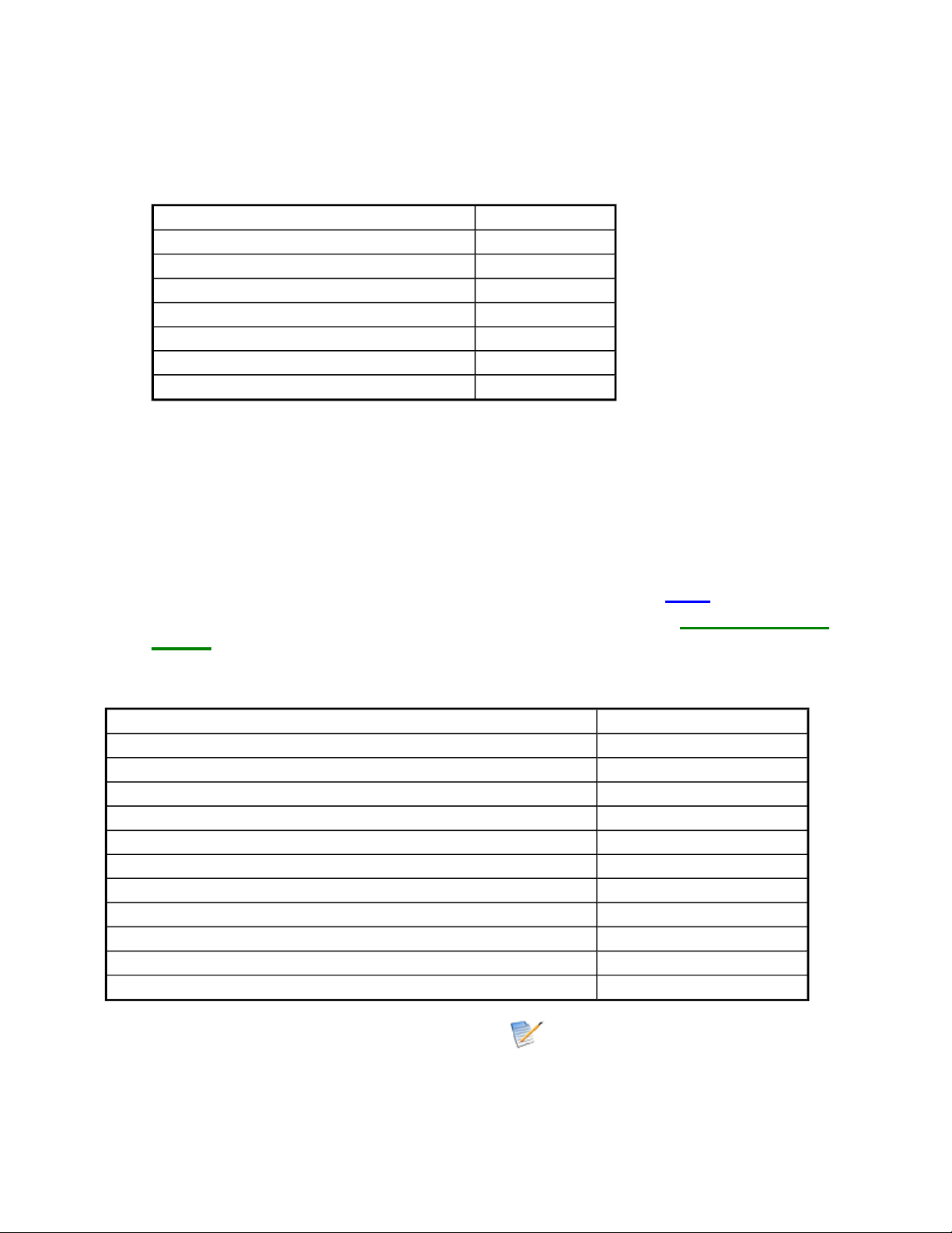
Press 3rd gear and No. 2 hub sleeve on output shaft. Select and install snap ring from NO. 2
HUB SLEEVE SNAP RINGS table that will allow minimum axial end play. Using feeler
gauge, measure 3rd gear thrust clearance to ensure it is correct.
3.
NO. 2 HUB SLEEVE SNAP RINGS
Mark Thickness (mm)
C-1 1.75-1.80
D 1.80-1.85
D-1 1.85-1.90
E 1.90-1.95
E-1 1.95-2.00
F 2.00-2.05
F-1 2.05-2.10
Install synchro ring on 2nd gear and align ring slots with shifting keys. Install needle roller
bearing in 2nd gear. Press 2nd gear and No. 1 hub sleeve onto shaft.
4.
Install locking ball in output shaft. Apply gear oil to needle roller bearing and assemble 1st
gear, synchro ring, needle roller bearing and bearing inner race.
5.
Install assembly on output shaft with synchro ring slots aligned with shifting keys. Turn
inner race to align with locking ball.
6.
Press bearing on output shaft with outer snap ring groove toward rear. Using feeler gauge,
measure 1st and 2nd gear thrust clearance to ensure it is correct. See Fig. 5 .
7.
Press 5th gear on end of output shaft. Select and install snap ring from 5TH GEAR SNAP
RINGS that will allow minimum axial end play.
8.
5TH GEAR SNAP RINGS
Mark Thickness (mm)
A 2.67-2.72
B 2.73-2.78
C 2.79-2.84
D 2.85-2.90
E 2.91-2.96
F 2.97-3.02
G 3.03-3.08
H 3.09-3.14
J 3.15-3.20
K 3.21-3.26
L 3.27-3.32
INPUT SHAFT & FRONT BEARING RETAINER
Inspect input shaft and bearing for wear or damage. If necessary, press new bearing on input
shaft. Select and install snap ring from INPUT SHAFT SNAP RINGS table that will allow
minimum axial end play.
1.
Page
14
of
19
OVERHAUL
-
G52 & G53 5
-
SPEED
-
1987 Toyota 4Runner
10/5/2009
http://www.ondemand5.com/mric/common/asp/printart.aspx
 Loading...