


7FBMF 18
Toyota 7FBMF 18, 7FBMF 25, 7FBMF 16, 7FBMF 30, 7FBMF 20 Repair Manual
...
7FBMF 16~18, 7FBMF 20~25
7FBMF 30~35, 7FBMF 40~50
AUGUST 2002 Pub. No. PE313
ELECTRIC FORKLIFT TRUCKS
7
FBMF 16,18
7
FBMF 20,25
7
FBMF 30,35
7
FBMF 40,45,50
< Tillbaka till Servicemanual 7FBMF 16-50
Index
AUGUST 2002
Pub. No. PE313

SECTION INDEX
NAME SECTION
GENERAL
DEVELOPMENT OBJECTIVES
CONTROLLER
MULTIPLE DISPLAY
BATTERY
POWER TRAIN
STEERING & REAR AXLE
TIRES
OPERATOR’S COMPARTMENT
0
1
2
3
4
5
6
7
8
BODY & ACCESORIES
MATERIAL HANDLING & HYDRAULICS SYSTEM
SAS
MAIN OPTIONS & ATTACHMENTS
WIRING DIAGRAM
9
10
11
12
13

FOREWORD
This manual mainly describes the development objectives of new Toyota forklift
7FBMF16~50 models, outlines of main component units, structures and functions
of new mechanisms and other technical features.
Please read it carefully for sales and service activities.
This manual has been edited for the vehicles launched into the market in September
2002.
Any later change shall be informed through Toyota Industrial Equipment Parts &
Service News.
Please refer to the repair manual and parts catalog for the matters necessary for
servicing.

0-1
0
1
2
3
4
5
6
7
8
9
1
0
11
1
2
1
3
GENERAL
Page
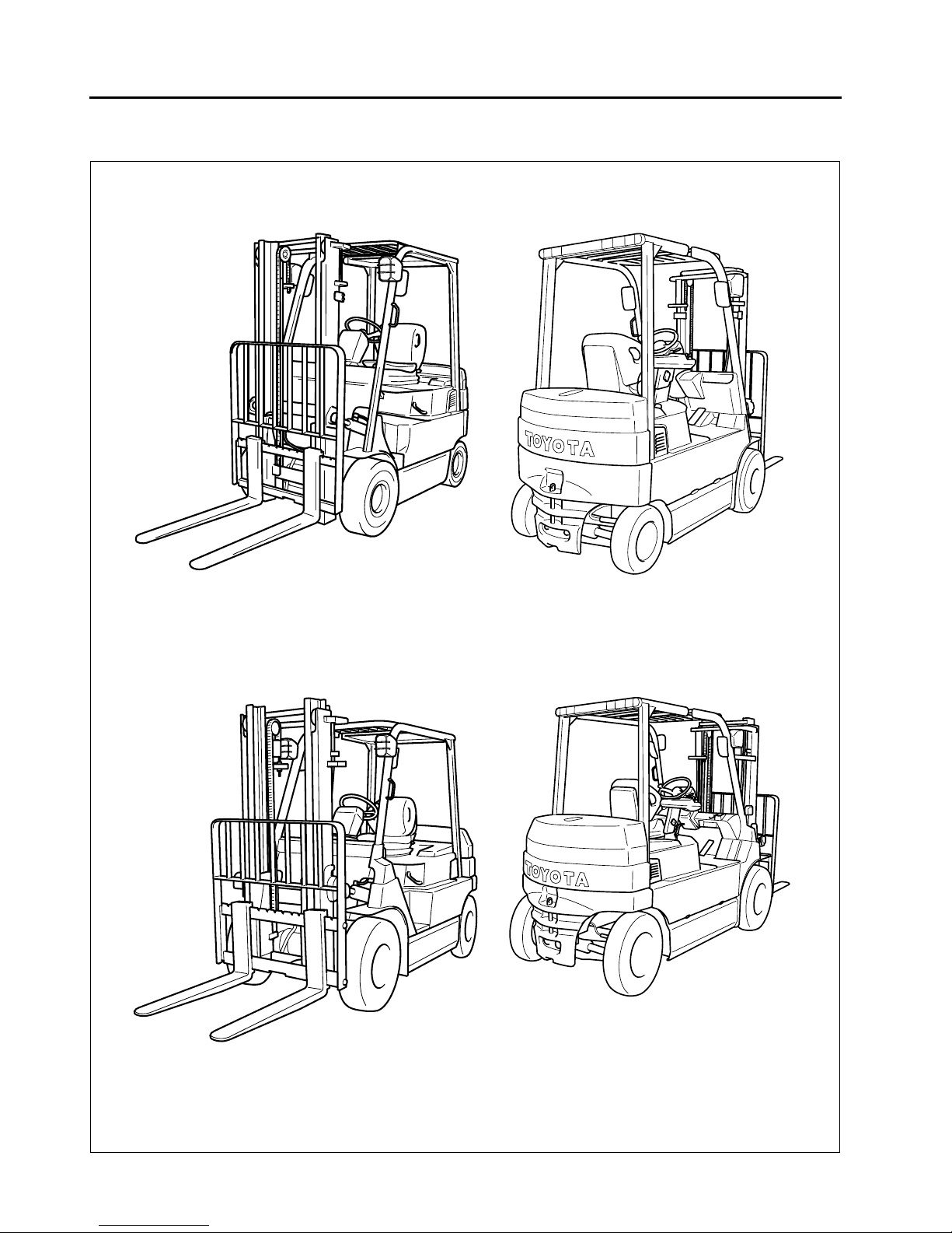
VEHICLE EXTERIOR VIEWS
..................................................0-2
MODEL LINE-UP
........................................................................0-3
STANDARD EQUIPMENTS
.....................................................0-4
0-2
VEHICLE EXTERIOR VIEWS
7FBMF16~35
7FBMF40~50
0-3
MODEL LINE-UP
Models
Frame number stamping
Capacity
(Load Center 500 mm)
Model (80V or 72 V)
New Previous
1 ton Series
1.6 ton 7FBMF16 FBMF16
1.8 ton 7FBMF18 —
2 ton Series
2.0 ton 7FBMF20 FBMF20
2.5 ton 7FBMF25 FBMF25
3 ton Series
3.0 ton 7FBMF30 FBMF30
3.5 ton 7FBMF35 —
4 ton Series
4.0 ton 7FBMF40 —
4.5 ton 7FBMF45 —
5.0 ton 7FBMF50 —
Model
Stamping Style
(Starting Number)
Stamping Location
7FBMF16
7FBMF18 10011
Stamp on LH & upper surface of front cross plate
7FBMF18
7FBMF20
7FBMF25 10011
7FBMF25
7FBMF30
7FBMF35 10011
7FBMF35
7FBMF40
7FBMF50 10011
7FBMF45
7FBMF50
0
1
2
3
4
5
6
7
8
9
1
0
11
1
2
1
3

0-4
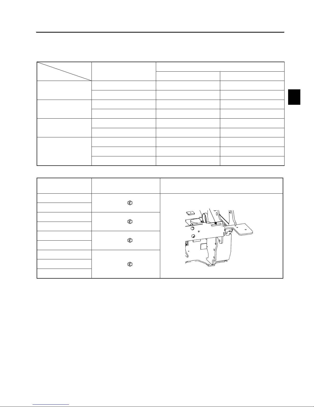
STANDARD EQUIPMENTS
: STD P:OPT —: Not Available
Standard Equipment 1.6-3.5 ton 4.0-5.0 ton Note
Electrical
System
AC Power system for travelling & load handling
AC Power controller for steering — 1.6-3.5 ton: DC system
Multiple display (All round model) P P
Chassis SAS (System of Active Stability)
Wet brake system
Parking brake system of electric switch type
Full hydraulic power steering
Body Overhead guard
Memory tilt steering column
ORS seat
Floor mat
Battery hood damper
Assist grip (LH)
Instrument panel holder
Paper clamp on battery hood
Drawbar pin
Load
Handling
System
Wide visible mast (V) H3300 mm
Load bucharest H1220 mm
Fork 1.6~1.8 ton: L800 mm
2.0~5.0 ton: L1000 mm
Mini-lever control system
3-way valve (A400)
Others Electric horn
Headlight P P
Rear-view mirror P P

1-1
0
1
2
3
4
5
6
7
8
9
1
0
11
1
2
1
3
DEVELOPMENT OBJECTIVES
Page
DEVELOPMENT OBJECTIVES
..............................................1-2
FEATURES (SELLING POINTS)
............................................1-3
AC POWER SYSTEM
................................................................1-6

1-2
DEVELOPMENT OBJECTIVES
TOYOTA 1.6 ~ 3.0 ton FBMF 16 ~ 30 counterbalance type electric 4-wheel forklift trucks have had an established reputation as high performance forklift trucks since first their model launched in 1989.
There have been rising demands for clean electric forklift trucks with relevant to environmental concern; and further the market wants higher capacity forklift than 3.0 ton beside the existing capacity models.
Keeping these points in mind, the design concepts were established, as follows:
1. AC induction motor
Making best use of the advantages of AC induction motor drive system to respond to customer's needs for the
most suitable load handling system.
2. SAS - System of Active Stability
In order to gain better stability, SAS has been developed. SAS, adopted by 7 series, has already won high confidence from the industrial truck markets.
This same level of stability will be incorporated into the new 7FBMF 16 ~ 50 models.
3. Introducing larger capacity models of 3.5 ton and over in addition to new 1 ~ 3 ton capacity models to enhance the product range.
Creation of over 3.5 ton capacity models has been undertaken together with the model changes launched for 1
~ 3 ton capacity models.
Most of all, the AC induction drive motor system has been a pioneering endeavor having rallied our technological
powers for a successful introduction in our products. Excellent features inherent to AC induction motor have
been used to its full advantages with success.
Furthermore, varied demands for additional features have been implemented. Emphasis has been placed on
system design development such as the mini-lever system and the wet brake system, etc.
The 7FBMF 16 ~ 50 models certainly have outstanding features compared to other forklift models. On operation,
the differences are so obvious in fundamentals, performance, comfort, etc. New 7FBMF 16 ~ 50 models are
commendable as an epoch in new era.
1-3
FEATURES (SELLING POINTS)
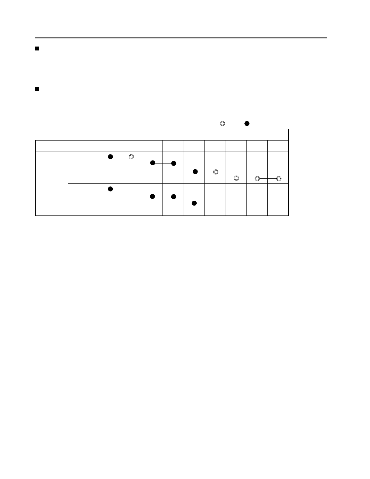
Table of selling points
mfr: manufacturer
: Newly adopted, : Improved
S: STD, P: OPT, –: Not available
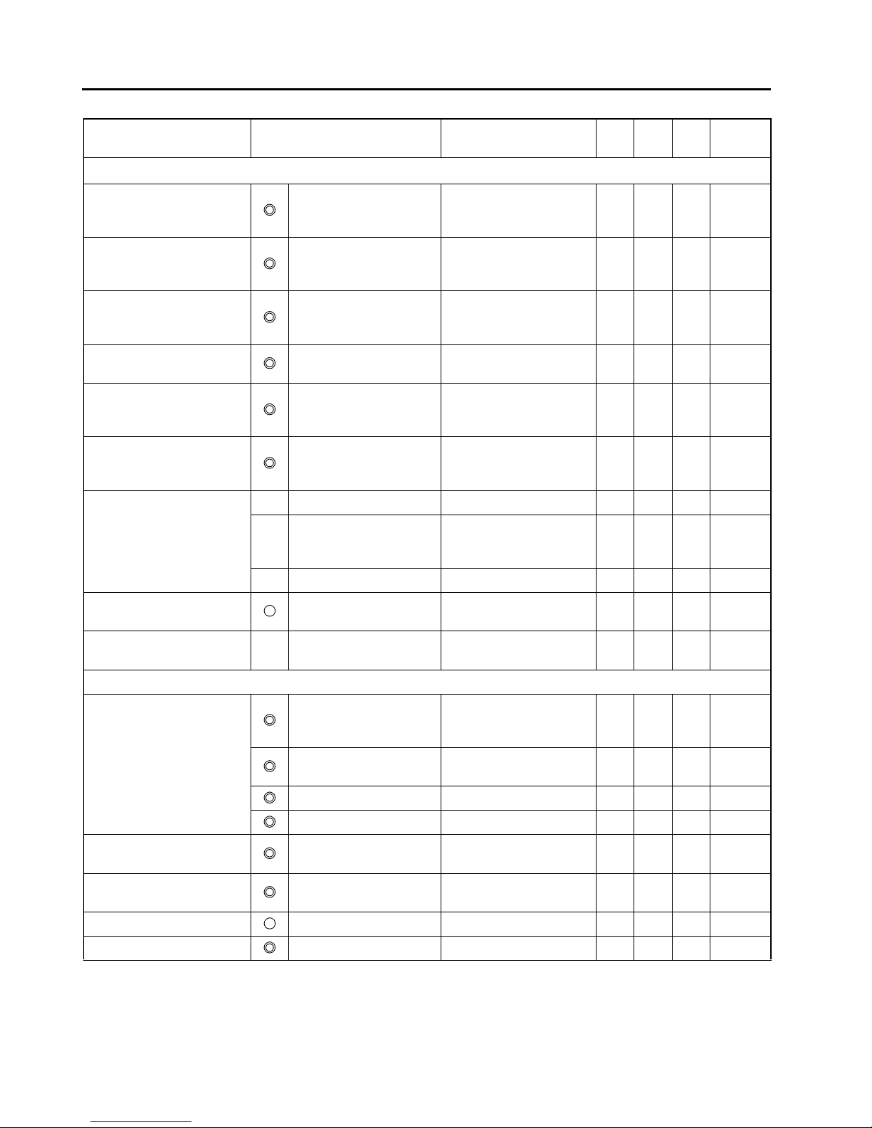
Selling point Function or Item Objective
1.5
~
3.5t
4.0 ~
5.0t
mfr A
Relative
page
Improved performance
Improvement in operation
hours and work cycles without
an operator noticing a decline
in performance
Power keep function Better performance at a low
battery level
SS—
1-8
2-2
Availability of different power
modes for different needs:
H mode: High power mode
P mode: Power mode
S mode: Standard mode
Other customized modes are
available as well.
Power select function A touch on a switch selects
optimum power mode.
S
S—
1-11
2-2
Load handling power
control
S
Improvement on operator comfort
Improvement in ease of
getting on and 0ff
The entry area has been
widened by installing the
battery under floor
Ease of getting on and off
equivalent to the enginepowered model
SS—1-10
Increased leg space Expansion of foot space S S — 1-10
Improved serviceability
Improved serviceability AC motor Need for servicing motor
brushes is eliminated.
SS—1-7
Overheat protector Power is reduced
automatically when motor is
overheated.
SS—
2-5
5-2
AC controller Need for servicing contactor
is eliminated.
SS—2-2
Thermal protector Output is reduced
automatically when
controller is overheated.
SS—
2-5
5-2
Reduced need for servicing
brake
Wet brake system Service life of brake system
is prolonged
SSS5-10
Regenerative system
(accelerator off)
Service life of brake system
is prolonged.
SSS2-5
Higher safety during servicing Jacking points under the
counter weight and frame
Jacking points indicated for
higher safety
SS—9-2
0
1
2
3
4
5
6
7
8
9
1
0
11
1
2
1
3
1-4
Selling point Function or Item Objective
1.6 ~
3.5t
4.0 ~
5.0t
mfrA
Relative
Page
Safety
Improved turning stability SAS-active control rear
stabilizer
Rear wheel ground grip
force increased when
required
SS—11-6
Improved material handling
stability
SAS-active mast function
controller (front tilt angle
control)
Controls front tilt angle for
high lifting, etc. S S — 11-10
Load collapse reduction SAS-active mast function
controller (rear tilt speed
control)
Controls rear tilt speed for
high lifting, etc. S S — 11-10
Operation error prevention for
lift lever
SAS-active mast function
controller (key-lift interlock)
Prevents unintended fork
lowering
SS—11-10
Large reduction of natural
drop and front tilt (1/3 of
previous values)
SAS-active mast function
control (key-lift interlock)
Cuts off valve oil leaks
when the key switch is
turned OFF.
SS—11-10
Easy monitoring of SAS
operation status
SAS-operation monitor,
indicator lamp, and
diagnosis
Easy recovery from SAS
faults S S — 3-2
Availability of maximum travel
speed control
Speedometer Large display easy to see S S — 3-4
Speed alarm Warning is given when
travel speed exceeds
preset level.
PP—3-5
Speed limiter Sets limits to travel speed S S — 3-4
Improved visibility High-mount rear
combination lamps
Visibility of forklift truck from
surrounding area
PP—9-6
Forward view Super-wide visible mast Maintains advantages of
internal width of wide mast.
SS—10-2
Operability, etc.
Easy operation SAS-active mast function
control (automatic fork
leveling control)
Automatically sets the mast
vertical. S S — 11-12
Steerage, load handling
lever, accelerator pedal
Reduced operation power
SS— —
Mini-lever S S P 10-12
Anti roll back S S S 2-5
Improved traveling stability Regenerative system
(accelerator off)
Regenerative braking
equivalent to engine brake
SS—2-5
Smooth and quick switchback
operation
AC motor and AC controller Quick switchback operation
without time lag
SS—2-5
Improved meter of screen Multiple display Legible display S S — 3-2
Battery roll out PP—12-3

1-5
Outline of Design
Major differences from previous models
Item New models Previous models
Relative
page
Applicable
model
Applicable
model
General Overhead guard
height
2195mm 1.6 ~ 1.8 ton 2160mm 1.6 ton
—
2195mm 2.0 ton 2180mm 2.0 ton
2215mm 2.5 ton 2180mm 2.5 ton
2215mm 3.0 ~ 3.5 ton 2275mm 3.0 ton
2310mm 4.0 ~ 5.0 ton — —
Wheelbase 1420mm 1.6 ~ 1.8 ton 1360mm 1.6 ton
1580mm 2.0 ~ 2.5 ton 1505mm 2.0 ~ 2.5 ton
1725mm 3.0 ~ 3.5 ton 1650mm 3.0 ton
2080mm 4.0 ~ 5.0 ton — —
Motor Drive motor
(72V/80V)
AC: 12.0 / 13.3 kw 1.6 ~ 1.8 ton DC: 7.6 / 8.6 kw 1.6 ton
5-2AC: 15.4 / 17.1 kw 2.0 ~ 3.5 ton DC: 10.1 / 10.6 kw 2.0 ~ 3.0 ton
AC: 14.9 / 16.6 kw 4.0 ~ 5.0 ton — —
Pump motor
(72V/80V)
AC: 12.0 / 13.5 kw 1.6 ~ 1.8 ton DC: 11.5 / 13.0 kw 1.6 ton
10-27
AC: 16.9 / 18.6 kw 2.0 ~ 2.5 ton DC: 14.8 / 17.0 kw 2.0 ~ 2.5 ton
AC: 16.9 / 18.6 kw 3.0 ~ 3.5 ton DC: 16.5 / 18.5 kw 3.0 ton
AC: 22.8 / 25.4 kw 4.0 ~ 5.0 ton — —
PS motor
(72V/80V)
DC: 1.0 / 1.1 kw 1.5 ~ 3.5 ton DC: 1.0 / 1.1 kw 1.5 ~ 3.0 ton
10-27
Same motor for PS as well as hydraulic oil
pump
4.0 ~ 5.0 ton — —
Controller Traveling Main controller & traveling motor driver 1.6 ~ 5.0 ton
Traveling & load handling controller 1.6 ~ 3.0 ton
Section
2, 11
Load handling Main controller & load handling motor driver 1.6 ~ 3.5 ton
SAS Controller of SAS
includes the steerage control
1.6 ~ 5.0 ton —
Steerage 1.6 ~ 3.5 ton Steerage con troller 1.6 ~ 3.0 ton
Controller of main
includes the steerage control
4.0 ~ 5.0 ton — —
Brake
mechanism
Main brake Wet brake 1.6 ~ 5.0 ton Dry brake 1.6 ~ 3.0 ton 5-10
Parking brake Parking brake system of electric switch type 1.6 ~ 5.0 ton Parking brake lever of ratchet type 1.6 ~ 3.0 ton 5-13
SAS
equipment
SAS specifications SAS-active control stability
1.6 ~ 5.0 ton
——11-6
Mast function control
• Front tilt angle control
• Rear tilt speed control
• Automatic fork leveling control
• Key-lift interlock
——11-10
Frame Overhead guard
Clearance
1055mm 1.6 ~ 3.5 ton 1030mm 1.6 ~ 3.0 ton
Section
9
1075mm 4.0 ~ 5.0 ton — —
Step height
525mm
1.6 ~ 1.8 ton 515mm 1.6 ton
2.0 ton
540mm 2.0 ~ 2.5 ton
545mm
2.5 ton
3.0 ~ 3.5 ton 675 (2nd) /160 (1st) 3.0 ton
535mm 4.0 ~ 5.0 ton — —
Underclearance
Center of Wheelbase
(Without load)
90mm
1.6 ~ 1.8 ton 110mm 1.6 ton
2.0 ton
130mm 2.0 ~ 2.5 ton
110mm
2.5 ton
3.0 ~ 3.5 ton 225mm 3.0 ton
150mm 4.0 ~ 5.0 ton — —
Others Floor mat Equipped 1.6 ~ 5.0 ton Nothing 1.6 ~ 3.0 ton
—
Material handling lever Mini-lever with armrest 1.6 ~ 5.0 ton Manual lever on the front cowl 1.6 ~ 3.0 ton 10-12
Seat ORS seat with seat belt 1.6 ~ 5.0 ton Seat with seat belt 1.6 ~ 3.0 ton 8-4
0
1
2
3
4
5
6
7
8
9
1
0
11
1
2
1
3

1-6
AC POWER SYSTEM
AC system in industrial trend
Industries have already employed AC power system by making use of its features. Three major features are:
Thereby industrial truck engineers worldwide have already been aware of the splendid features of AC power system to be implemented in electric forklift trucks.
New AC drive motor systems have been adopted not only in the smaller capacity models, but also in the larger
capacity models. This new system resolves the opposing factors between larger output necessity and compactness.
System design
advantages
Product level
advantages
Industry 1970 80 90
1
Simpler and smaller
construction of motor
More powerful motor can
be used without
increasing size.
Machine tool
2
Three-phase AC control
realizes wider control
range.
Wide control range offers
a higher performance
and operability.
Train
3
Motor brushes and
contactors are
dispensed with.
Reduced maintenance
cost as the needs for
servicing motor brushes
and contactors are
eliminated.
Electric
Automobiles (EV)
Electric Forklifts
DC AC
DC AC
DC AC
DC
1-7
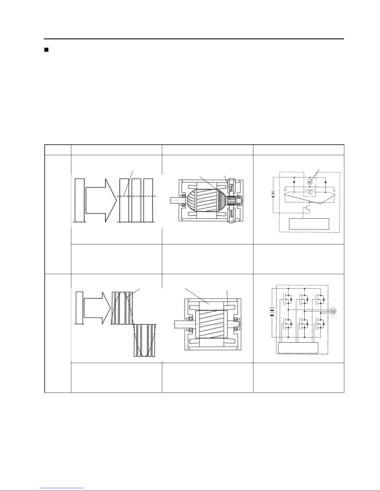
AC power system as compared with DC power system
In the DC power system the controller will chop the battery current in repetition and control the frequency
cycles of ON and OFF. The motor performance will change in proportion with the frequency cycles between
ON and OFF, thereby the inching at start to the max. performance is controlled.
The AC power system in the new models includes a controller that transforms the battery current into a threephase alternating current. The motor power is controlled by changing the sinusoidal waveform (frequency,
amplitude, etc.) of the three-phase alternating current.
Motor drive voltage, motor construction, and controller details differ between DC and AC power systems, as
follows:
Comparison between DC and AC power systems
Motor voltage Motor construction Controller
DC power
system
• A chopper circuit converts the battery current (DC) into a rectangular
waveform and controls the mean
voltage at a desired level.
• Brushes and commutator require
servicing.
• Complex mechanism
• Motor power can be controlled simply via the mean DC voltage.
• Contactors for reversing the motor
rotation are required.
AC power
system
• Controller converts battery current
(DC) into AC.
• Brushes and commutator, which require servicing, arer not used.
• Compact and lightweight
• A control module converts DC into
three-phase AC.
• Contactor for reversing the motor
rotation are not required.
Controller
ON
Mean voltage
Mean voltage
Battery
voltage
OFF
Commutator
Brush
Battery
Motor
Contactor
Microcomputer
control
Sine wave
Controller
Motor
voltage
Battery
voltage
Stator coil
Stator ferrit core
Motor
Battery
Microcomputer
control
1-8
Power keep function
(Functions in power mode: P, standard mode: S)
Power keep function using the benefit of AC power system further lengthen the operation hours epochally.
With conventional electric powered forklift trucks, the vehicle performance decreases gradually as the battery
level goes low.
The power keep function adopted to new models takes advantage of the increased controllability provided by
the AC system to keep the vehicle performance even when the battery level has become low. With this power
keep function, the maximum operating hours have increased by 25%, and the number of work cycles that can
be completed without the operator noticing a decline in performance has also increased by 25%.
New power keep function offers a significant and essential improvement in the material handling efficiency.
(See page 2-2 for further detail.)
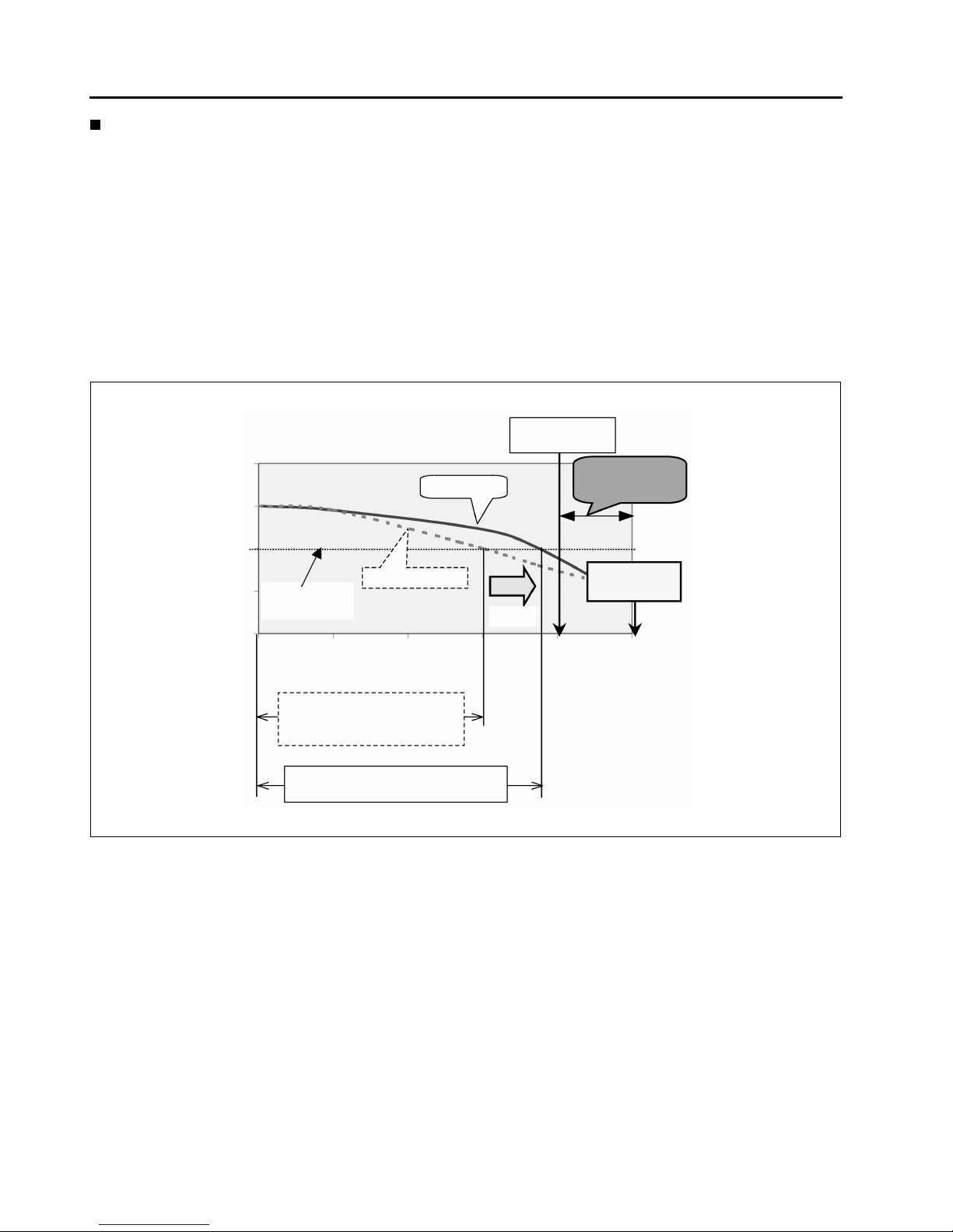
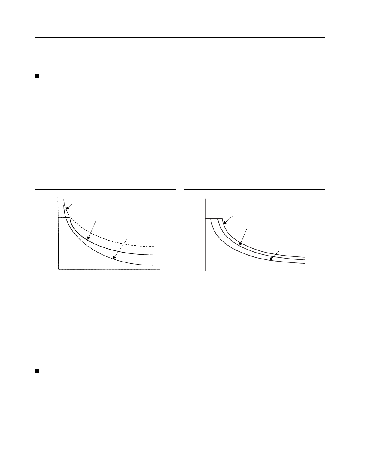
Battery discharge level and vehicle performance
Even the battery indicator is flashing to indicate the charge warning, the performance level of 7FBMF series is
batter than that of the former FBMF models.
In view of the battery protection, it is advisable to charge the battery before discharging to the limit.
Battery capacity
warning
Battery usage
limit area
Lift
interruption
New model
Previous model
Decrease in
performance
25% up
Battery discharge level (%)
Previous model (2.5 ton:S mode)
Efficiency operation hour:
161min
New model (2.5 ton:S mode)
Efficiency operation hour: 200min
1.1
1
0.9
0.8
0.7
0%
20% 40%
60%
80% 100%

1-9
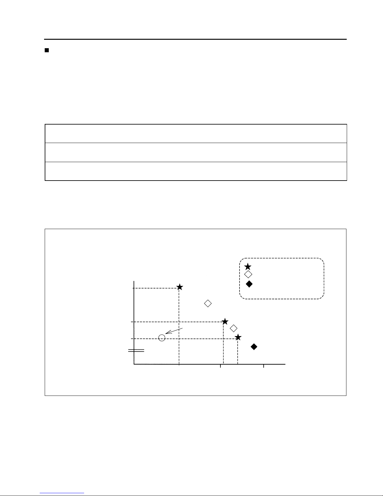
Performance features in comparison
2.5 ton
Traveling speed (km/h)
[a]
Acceleration (sec)
[b]
Slope climbing speed (km/h)
[c]
Efficiency operation hours (min)
[d] (Toyota 30m cycle)
No of cycle (cycle)
[e] (Toyota 30m cycle)
4.5 ton
Traveling speed (km/h)
[f]
Acceleration (sec)
[g]
Slope climbing speed (km/h)
[h]
Efficiency operation hours (min)
[i] (Toyota 50m cycle)
No of cycle (cycle)
[j] (Toyota 50m cycle)
*: Loaded *Loaded: 0-10m
*Loaded: 1/10 slope
16
14
14
14
16
4.6
5.3
5.7
5.3
5.2
6.9
5.6
5.6
5.3
7.0
HPSFBMF
mfrA H P S FBMF
mfrA
HPSFBMF
mfrA
*Battery 500Ah
*Battery 500Ah
125
185
200
161
163
88
131
138
111 112
HPSFBMF
mfrA H P S FBMF
mfrA
*Loaded *Loaded: 0-10m
*Loaded: 1/10 slope
HPS
mfrA
HPS
mfrA
HPS
14
13 13 13
5.4
5.9
6.3
5.7
4.8
3.4 3.4
*Battery 700Ah
*Battery 700Ah
HPS
mfrA
HPS
mfrA
133
204
218
174
67
96
100
80
mfr: manufacturer

1-10
Operator comfort
(1) Improvement of the ease of getting on and off
By new battery layout, improved the ease of getting on and off
Entry clearance (2.5 ton) [a]
(2) Improvement of comfort
By new battery layout, improved the leg space
Leg space (2.5 ton) [b]
(mm)
560
290
260
7FBMF
FBMF
mfrA
(mm)
640
604
555
7FBMF
FBMF
mfrA
1-11
Power select function
Using the power select function, the operator can select a desirable power mode.
Even though the conventional models also had a power selection switch, it only produced a small difference in
the acceleration.
New models use an AC motor instead of a DC motor.
Since and AC motor is simpler and smaller, it becomes possible to install a motor that produces an output higher
than that of a conventional DC motor.
In addition, the operator can select appropriate mode from the following power modes simply by operating a
switch.
In order to further satisfy the individual customer, a power select function has been provided.
The power select function enables the operator to select one from six power modes, including H, P and S modes,
for traveling. The operator can select H mode for operations requiring power and high performance. Select S
mode for long time operations, providing the operator with optimum performance to suit the operator’s needs
and greatly enhance efficiency.
• High power mode
<H mode>
: The most active mode with the quickest cycle-time
• Power mode
<P mode>
: The highest efficiency mode with quick cycle time and long operation hour
• Standard mode
<S mode>
: The longest operation hour mode with the performance equivalent to MFRA
<7FBMF25>
Cycles
High power mode
<H mode>
: Fixed mode
: Selectable only through
power select function
: Power select function
default setting
180min 240min
Power mode
<P mode>
Standard mode
<S mode>
30m cycle pattern
Efficient operation hours
44
42
43
41
Previous
model

1-12
Reduced maintenance cost
The following particular items are inherent to the conventional electric powered models.
Supplying distilled water to the battery
Material handling motor brush replacement
Material handling motor contactor replacement
Traveling motor brush replacement
Traveling motor contactor replacement
The new 7FBMF model eliminates the need for brush and contactor replacement because the new AC motor
does not have brushes and the new AC controller does not have contactors.
The average customer can benefit from this by an annual cost savings of 69% for maintenance expenditures.
Taking advantage of the wider control range of the AC power system, a regenerative system is adopted.
The AC induction motor generates a braking force when the vehicle is traveling with the accelerator pedal at rest.
Also the electromotive force generated in the AC motor, while the accelerator pedal is released, converts the
braking effect energy into electrical energy that is sent to the battery.
This regenerative system increases the operation hours. At the same time, the regenerative system improves
the traveling feel because it allows the operator to use less brake pedal force to slow the truck down. Furthermore, the regenerative system reduces load on the brake system, slowing down brake lining wear and decreasing the brake maintenance costs.
3
2
4
5
1 1
1460 (1490)
1Eur = 0.98USD
451 (460)
New model
Previous
model
0
500
1000
1500
Eur (USD)
519
294
127
69
451
Annual Cost Saving 69%
by Eliminating ~

1-13
Stabilizing features
The world-first System of Active Stability (SAS), adopted by the 7FB series models, is available for the new models, too.
Using the SAS the new models achieve the stability level equivalent to that achieved by the 7FB series models.
The following outlines the SAS. For more details of the SAS option, refer to Section 11 “SAS”.
Improvement on operability
1. Mini lever
The hydraulic control levers are displaced to the arm rest fore-front and optimal length, and spacing are
given on basis of human engineering. An operator can manipulate the control lever with a hand on the
arm rest. Fine operation adjustment can be achieved with the display. The control lever position is adjustable vertically as well as to lengthwise.
Pleasant material handling operation with less fatigue can be ensured.
Stability feature Outline
Rear stabilizer (swing lock) The rear wheel swing mechanism is locked at high lift-heights and
heavy loads, and during a quick turn to obtain a better ground grip
force from all four wheels.
Mast function control
Front tilt angle control The front tilt angle is smaller at high heights and heavy loads;
greater at low heights and light loads.
Rear tilt speed control The rear tilt speed is slower at high heights and faster at low
heights.
Key-lift interlock The lift lever cannot function by inadvertent contact.
Automatic fork leveling control A push on a control button followed by a front tilt operation tilts the
mast until the forks are horizontal.
1-14
Anti-rollback
The anti-rollback function is provided to prevent the truck from rolling down on a slope. This is realized by making
use of the combined features of the drive motor electric brake and the parking brake.
Restarting can be done smoothly without rolling down.
Model line-up
The model line-up has been widened by the development to 3.5 ~ 5 ton class new model ranges; besides, the
1.8 ton model is added onto the 1 ~ 3 ton classes to meet with varied needs from the markets.
: New : Continuation
Capacity (kg)
1600 1800 2000 2500 3000 3500 4000 4500 5000
TOYOTA
7FBMF
FBMF

2-1
0
1
2
3
4
5
6
7
8
9
1
0
11
1
2
1
3
CONTROLLER
Page
MAIN CONTROLLERS
.............................................................2-2
General
.................................................................................2-2
Controller Configuration Diagram
.............................. 2-3
MAIN FEATURES OF CONTROLLER
.................................2-5
2-2
MAIN CONTROLLERS
General
AC system
The AC motor drive system controller has been provided with:
• Microcomputer-assisted travel inverter control (converts DC to three-phase AC)
• CAN (Controller Area Network) communication function between main controller and traveling/material handling controller.
• Communication function between multiple display and SAS controller.
This is a multi-functional controller with advanced electronics technology.
The controller offers the power select function and power keep function that take full advantage of the AC power
system.
Power select function: Allows the operator to select from three traveling modes, H (High power) mode, P (Power) mode, and S (Standard) mode.
Power keep function: Maintains a high performance level even when the battery level becomes low and increases stress-free operation hours. (Available when P or S mode is selected.)
Compared with a DC motor of an equivalent size, an AC motor has a higher output.
The output characteristics of an AC motor are determined by the amplitude and frequency of the alternating current output by the controller.
The controller has a map stored in its memory of the optimum combinations of the current and frequency. Using
these, the optimum output characteristics can be obtained for all conditions. When the power selection switch is
operated, the controller switches the map and changes the output characteristics. The power select function thus
enables the output characteristics to be changed in accordance with the vehicle usage conditions.
Power keep function
With a DC power system, the output characteristics are determined by the controller output voltage. The maximum output, therefore, is the output from the motor when the battery voltage is fully applied (chopper duty
100%). The output will decrease with the battery voltage as the battery is discharged.
With an AC power system, however, it is possible to maintain a high performance even when the battery level
becomes low because the combination of the amplitude and frequency of the alternating current is changed as
the battery level goes low.
Compared to the DC motor, the AC motor has
higher output and a range of output characteristics is obtainable from the increased output.
When the battery is discharged, the AC motor
provides output characteristics closer to those of
a fully charged battery than a DC motor does.
Torque
AC motor maximum output
AC power system output
characteristics
DC power system output
characteristics (DC motor
maximum output)
Revolution
Torque
Revolution
AC and DC power system output
characteristics with fully charged battery
AC power system output
characteristics with discharged battery
DC power system output
characteristics with
discharged battery
2-3
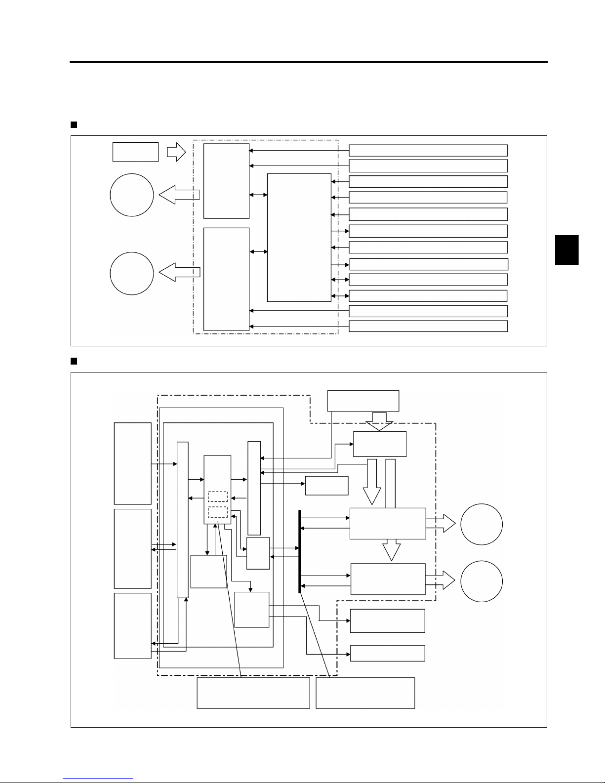
Controller Configuration Diagram
1. Traveling & Load handling controller
System configuration diagram
Controller internal configuration diagram
Battery
Traveling
AC motor
Material
handling
AC motor
Traveling
motor
driver
Material
handling
motor
driver
Main
controller
Traveling motor temperature sensor
Traveling speed sensor
Direction switch
Traveling accelerator potentiometer
Brake switch
Parking brake valve
Material handling potentiometer
Oil control valve
SAS(with PS) controller
Multiple display
Material handling motor temperature sensor
Material handling speed sensor
Traveling and material handling controller
Traveling and material handling controller
Main controller
CPU board
Battery
Power supply
contactor
Sensors
and
switches
Traveling motor driver
Material handling
motor driver
Oil control valve
Parking brake valve
Comfortable operability is
realized by making fine control
using microcomputer.
CANBus
Controller Area
Network Bus
Multiple
display
SAS
(with PS)
controller
EEPROM
Solenoid
drive
circuit
CAN
I/O
CPU
RAM
ROM
Cooling fan
Traveling
AC motor
Material
handling
AC motor
I
/
O
I
/
O
0
1
2
3
4
5
6
7
8
9
1
0
11
1
2
1
3
2-4
CPU: Central Processing Unit
ROM: Read Only Memory (with built-in control program)
RAM: Random Access Memory (memory content lost when power turned off)
EEPROM:Electrically Erasable Programmable Read Only Memory (memorizes data required for control and er-
ror code.)
I/O: Input/Output interface
CANI/O: Controller Area Network Input/Output interface
2. SAS (With Power Steering) Controller
System configuration diagram
Controller internal configuration diagram
The portions marked with * are applicable only to 7FBMF 16 ~ 35 models.
CPU: Central Processing Unit
I/O: Input/Output interface
Battery
PS motor
PS circuit
Control circuit
Tire angle sensor
Wheel angle sensor
Swing solenoid
Knob position correcting valve
Main controller
SAS (with PS) controller
Tire angle sensor
Wheel angle sensor
Main controller
CPU board
CPU
Yaw rate
sensor
Power & solenoid
drive board
*PS motor drive
main circuit
Knob position
correcting valve
Swing solenoid
Battery
*PS motor
I
/
O
I
/
O
SAS (with PS) controller
I/O

2-5
MAIN FEATURES OF CONTROLLER
1. Regenerative system (accelerator off)
When the vehicle travels with the accelerator off, a braking force produced by the motor generates electricity,
which is retrieved by the battery. The working of the regenerative system extends the available operation
hours and the service life of brake linings. At the same time, the regenerative system improves the travel
speed controllability and stability because it allows the operator to use the soft braking force exerted by the
motor. Even if the direction lever is at the neutral position, the regenerative system will function when the
accelerator is off.
2. Regenerative system (brake pedal depressed)
Regenerative system is operated when the brake pedal is depressed as well, which allows to extend the
available operation hours and the service life of brake lining.
Even if the direction is at the neutral position, the regenerative system will function when the brake pedal is
depressed.
3. Regenerative system (switch back)
The switch back operation (It means the directional change during traveling) also regenerate electricity like
the previous model. Furthermore the AC controller in the new model has no contactor for traveling so that
the switch back operates smoother than before.
4. Power select function
Three traveling and material handling modes are available from a selection switch on the multiple display: H
(high power) mode, P (power) mode, and S (standard) mode.
5. Advanced power select function (option)
The advanced power select function allows the operator to select a traveling power mode and a material handling power mode independently from each other. It also allows the operator to define a mode other than H,
P, and S.
6. Power keep function
The power keep function maintains the vehicle performance at a high level even when the battery level is
low. With the new models, stress-free operation hours for a battery charged have increased.
(The power keep function is available only when the operator selects P or S mode.)
7. Auto-off system
If the operator leaves the vehicle with the key switch ON, the auto-off system forcibly shuts down the controller (equivalent to key switch OFF) after a preset period to prevent wasteful expenditure of energy. To restart the vehicle, turn the key switch OFF and then ON.
8. Seat switch
The seat switch does not allow the vehicle to travel as well as any material handling to operate by the minilevers unless someone is on the operator's seat.
9. Anti-rollback function
The anti-rollback function makes it easy to start the vehicle on an inclined surface. This function is achieved
by controlling both the drive motor and the brake system.
10. 2-speed travel speed control
The 2-speed travel speed control switch sets a speed limit.
The set value is adjustable by a switch on the multiple display.
11. Thermal Protector
Overheat warning:
Temperature in the controllers and motors are monitored by temperature sensors. If an abnormally high temperature is detected, the controller output is reduced to prevent overheating. The display will warn the operator.
0
1
2
3
4
5
6
7
8
9
1
0
11
1
2
1
3

2-6
12. Battery level computation
The controller monitors decrease in the battery voltage, computes the remaining capacity, and displays it as
the current battery level.
13. Diagnostic function
The diagnostic function can detect abnormalities in the traveling controller and the material handling controller, operation mechanisms such as the accelerator, and sensors. When an abnormality is detected, the diagnostic function outputs a diagnostic code and takes the appropriate measure.
14. Analyzer function
The multiple display has an analyzer mode that can be used for troubleshooting or for testing operation
mechanisms and motor drivers.
15. Over-discharge warning function
When the remaining capacity level reaches a specified level, the multiple display shows a warning and the
load handling operation is restricted.
This will protect the battery and will urge the operator to charge the battery.
It is possible to release this restriction temporarily by turning the key switch off at once before resetting as
emergency measures.
16. Return-to-neutral function
If the operator turns the key switch ON with the direction lever at the forward or reverse position or with the
accelerator pedal depressed, the vehicle will not start. The operator has to return the direction lever and accelerator pedal to their neutral positions once in order to allow it to restart.
17. Parking brake ON warning
The buzzer sounds when the operator attempt to start the truck with the parking brake switch turned ON.
18. Parking brake OFF warning
The buzzer sounds to warn the operator when moving from the drive seat without the parking brake switch
turned on.
19. Mini-lever control
Based on operation signals of the mini-lever, the main controller controls material handling operation by controlling solenoid valves and the material handling controller.

3-1
0
1
2
3
4
5
6
7
8
9
1
0
11
1
2
1
3
MULTIPLE DISPLAY
Page
MULTIPLE DISPLAY INDICATION
.......................................3-2
MULTIPLE DISPLAY FUNCTIONS
.......................................3-3
SERVICE FUNCTIONS
.............................................................3-9
3-2
MULTIPLE DISPLAY INDICATION
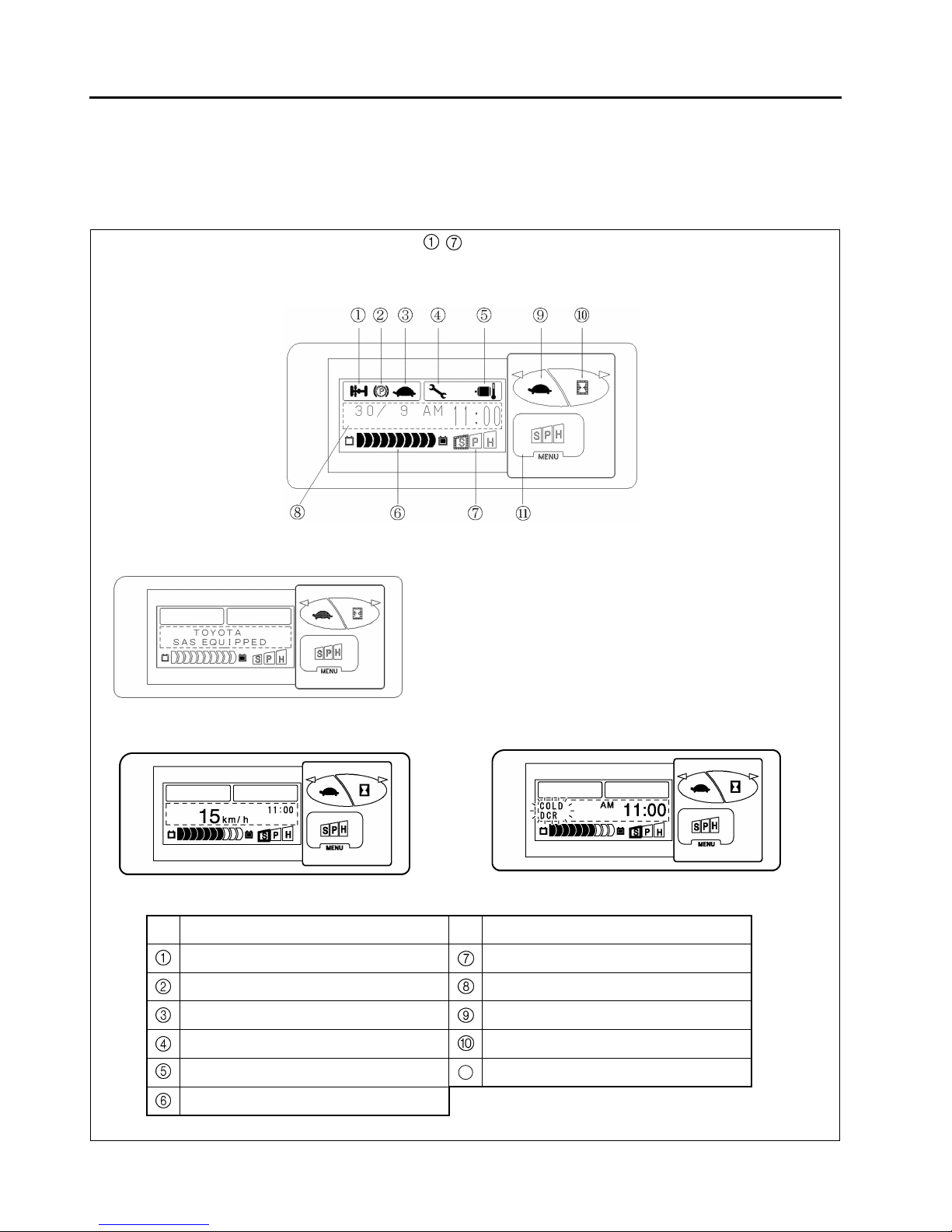
General
Various essential data with regard to the truck status, warning signs, setting, meters, etc. are visible by switching
display.
No. Description No. Description
Swing lock indicator Power select indicator
Parking brake indicator Multiple display area
Travel 2nd speed setting indicator Travel 2nd speed control set switch
Diagnostic mode indicator Hour meter select switch
Overheat warning indicator Power select switch
Battery capacity indicator
11
(Indication of - will be changed according to the functional operation.)
During parking
Initial screen after the key switching on
During traveling
Upon error occurrence
3-3
MULTIPLE DISPLAY FUNCTIONS
Table of Multiple Display Functions
: Available
—: Not available
Functions
Easy model
(standard)
All-round
model
(optional)
Status
display
Battery capacity indicator
Speedometer
Travel 2nd speed setting indicator
Swing lock indicator
Parking brake indicator
Power select indicator
Level
setting
Power select function
Travel power control level setting
Material handling power control level setting
Travel 2nd speed control level setting
Warning
Battery over-discharge warning
Low battery capacity warning
Overheat warning
Parking brake ON warning
Parking brake OFF warning
Return to neutral warning
Over speed alarm —
Diagnostic code display
Integrating
meters
Key switch on hour meter
Travel or material handling motors service hour meter —
Travel motor service hour meter —
Material handling motor service hour meter —
Lap time meter —
Odometer —
Trip meter —
Calendar/Clock
11
12
13
14
15
16
17
18
19
20
21
22
23
24
25
26
0
1
2
3
4
5
6
7
8
9
1
0
11
1
2
1
3
 Loading...