


Instruction Manual
The new generation high-performance inverter
TOSVERTTMVF-A7
200V class 0.4 90kW
400V class 0.75 280kW
NOTICE
1.Make sure that this instruction manual is delivered to the end user of the inverter unit.
2.Read this manual before installing or operating the inverter unit, and store it in a safe place for reference.
© TOSHIBA Schneider Inverter Corporation 2001
All Rights Reserved.
Safety |
I |
precautions |
|
Preface |
II |
Contents |
|
Read this |
1 |
section first |
|
Connection |
2 |
Operating |
3 |
the inverter |
|
Basic |
4 |
Operation |
|
Basic |
5 |
parameters |
|
Extended |
6 |
parameters |
|
Operation |
7 |
with external |
|
signal |
|
Monitoring |
8 |
operation |
|
status |
|
Peripheral |
9 |
units |
|
Table of |
10 |
parameters |
|
Specification |
11 |
Prior to |
12 |
service call |
|
Regular |
13 |
inspection and |
|
maintenance |
|
Warranty |
14 |
Precautions |
15 |
of disposal |
Safety precautions
The labels on the inverter and this instruction manual contain important instructions for the prevention of possible injury to the user and other persons and damage to property, as well as for the safe use of the inverter. Please gain a good understanding of the following pictorial symbols before reading this manual and strictly observe the instructions that follow each symbols.
Marking
Symbols |
Meaning |
Danger |
injuryMeans that improper use or handling could cause the risk of death or serious |
|
|
Warning |
Means that improper use or handling could cause injury to persons(*1) or |
damage to property(*2). |
|
|
|
(*1)”injury to persons” refer to injuries, burns, electric shocks, and so on, that do not oblige the injured person to be hospitalized or go to a hospital for a long period of time for medical treatment.
(*2)”damage to property” includes all kinds of losses resulting from it.
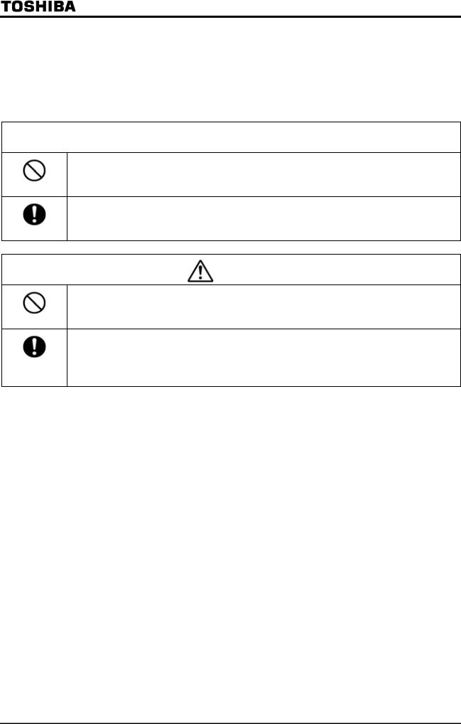
Symbols |
Meaning |
|
Represents prohibition(what you must not do) |
|
What you must not do is described in or near this symbol by a picture or words |
|
|
|
Represents mandatory items(what you must do) |
|
What you must do is described in or near this symbol by a picture or word |
|
Represents danger |
|
What is dangerous is described in or near this symbol by a picture or word |
|
Represents warning |
|
What the warning should be applied is described in or near this symbol by a picture or word |
|
|
■Limited applications
This inverter is designed to control the speed of three-phase induction motors for general industry.
 Precautions
▼When using our inverters for equipment such as nuclear power control equipment, aviation and space flight control equipment, traffic equipment, and safety equipment, and there is a risk that any failure or malfunction of the inverter could directly endanger human life or cause injury, please contact our headquarters, branch, or office printed on the front and back covers of this catalogue. Such applications must be studied carefully.
▼When using inverters for critical equipment, even though the inverters are manufactured under strict quality control always fit your equipment with safety devices to prevent serious accident or loss should the inverter fail(such as failure to issue an inverter trouble signal)
▼Do not use our inverters for any load other than three phase induction motors.
1
■Handling in general
|
|
|
Danger |
Reference |
|
|
|
|
|
|
|
|
Never disassemble, modify or repair the inverter. Its disassembly could |
2. |
|
|
|
cause an electric shock, afire or an injury. Request your TOSHIBA dealer |
|
Never |
for repair. |
|
||
Disassemble |
|
|
||
|
|
|
-Never open the front cover of the inverter(or the door of the cabinet in |
2. |
|
|
|
which the inverter is installed) when the inverter is energized, or you |
|
|
|
|
could get a shock since a high voltage is applied to certain portions of it. |
|
Prohibited |
-Do not put your fingers into the panel through a wiring opening or an |
2. |
||
opening in the cooling fan cover, or you could get a shock or an injury. |
|
|||
|
|
|
|
|
|
|
|
-Do not put or insert anything(e.g., electric cable, bar or steel wire) into the |
2. |
|
|
|
inverter, or the inverter could cause a shock or fire. |
|
|
|
|
-Do not splash water over the inverter, or the inverter could cause a shock |
2. |
|
|
|
or a fire. |
|
|
|
|
-Do not turn on the power before attaching the front cover (or closing the |
2. |
|
|
|
door of the cabinet in which the inverter is installed), or you could get a |
3. |
|
|
|
shock. |
3. |
Mandatory |
-Turn off the power immediately in case the inverter smokes, smells of |
|||
smoke, or produce abnormal noise. Failure to do so could lead to a fire. |
|
|||
|
|
|
|
|
|
|
|
In such a case, request your TOSHIBA dealer for repair. |
3. |
|
|
|
-Due to the possibility of contaminants entering the drive, disconnect the |
|
|
|
|
input power if the drive will be unused for extended periods. |
|
|
|
|
The leakage current caused by the contamination may result in fire. |
|
|
|
|
|
|
|
|
|
Warning |
Reference |
|
|
|
|
|
|
|
|
Do not touch any heat sink or braking resistor, or you could get a burn |
3. |
|
|
|
|
|
Never touch |
since they become very hot. |
|
||
|
|
|||
2
■Transportation Installation
|
Danger |
Reference |
|
|
|
|
-Do not install or operate the inverter if it is damaged or any part is missing |
2. |
|
from it. Operating the inverter in a defective condition could lead to a |
|
|
shock or a fire. Request your Toshiba dealer for repair. |
1.4.4 |
Prohibited |
-Do not put any inflammable material near the inverter, or it could catch a |
|
fire if the inverter sparks because of a breakdown, etc. |
|
|
|
|
|
|
-Do not install the inverter where it can be splashed with water, etc., or it |
2. |
|
could cause a shock or a fire. |
|
|
-Use the inverter under environmental conditions specified by this |
1.4.4 |
|
instruction manual, or it could break down. |
1.4.4 |
|
-Install the inverter on a non-combustible board, for example, a steel plate. |
|
Mandatory |
Installing it on a inflammable board or wall could lead to a fire because its |
|
back is heated up during operation. |
|
|
|
1.4.4 |
|
|
-Do not use the inverter with the front cover detached, or it could cause a |
|
|
shock. |
1.4.4 |
|
-Install an emergency shutdown device which matches the system (for |
|
|
example, a switch interlocked with the brake of the machine). Failure to |
|
|
do so could lead to injury to persons since it has no emergency stop |
|
|
function. |
|
|
-Do not use any optional devices other than those designated by our |
1.4.4 |
|
company. |
|
|
The use of improper devices could lead to accidents. |
|
|
|
|
|
Warning |
Reference |
|
|
|
|
-Do not hold the front cover to carry the inverter, or the cover could come |
2. |
|
off and cause the main unit to fall, thus causing you to get an injury. |
1.4.4 |
|
-Do not install the inverter in any place subject to vibration, or it could fall, |
|
Prohibited |
causing injury to persons. |
|
|
-For a model (20 kg or more in weight) designed for 30kW motors or larger, |
2. |
|
carry it at least in a twosome, or it could fall and cause you to get an |
|
|
injury. |
|
Mandatory |
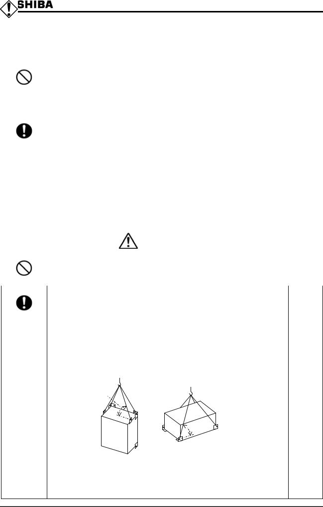
-Handle large capacity model using a crane. Lifting heavy inverter causes |
|
injury to persons. Taking care of safety for users, carefully handle in order |
|
|
|
not to damage to the inverter. |
|
|
Carefully lift up the inverter, hanging wires on the hanging bolts or halls |
|
|
on the top or bottom of the inverter. |
|
|
-Four points and perpendicular lifting is recommended. Even if |
|
|
perpendicular lifting is impossible, respect the condition described in the |
|
|
following figure. A crack may be attached to the product body when not |
|
|
performing perpendicular lifting. Please be careful. |
|
|
60° Max. |
|
 60° Max.
-Install the main unit on a wall, or the like, which is strong enough to |
1.4.4 |
withstand its weight, or it could fall and cause injury to persons. |
|
-Install a mechanical brake whenever the motor requires a brake (device |
1.4.4 |
which retains the motor shaft). Failure to do so could lead to injury to |
|
persons because the inverter itself has no function of mechanically |
|
retaining the brake shaft. |
|
3
■Wiring
|
Danger |
Reference |
|
|
|
|
-Do not connect the power cable to any output terminal (U/T1, V/T2 or W/T3 |
2.2 |
|
on the motor side), or the inverter could break down and cause a fire. |
2.2 |
|
-Do not connect a resistor to any D.C. terminal (between PA and PC or PO |
|
Prohibited |
and PC), or the inverter could cause a fire. |
6.13.4 |
To install external braking resistor, refer to 6.13.4. |
|
|
|
|
|
|
-Don’t touch the connector terminals and cables of the devices(MCCB) on |
|
|
he input side of the inverter within 10 minutes after shutting down the |
2.2 |
|
power source |
|
|
-Entrust all electrical work to an experienced specialist. Wiring by an |
2. |
|
inexperienced person could result in a fire or an electric shock. |
2. |
|
-Connect the output terminals (on the motor side) correctly. Incorrect |
|
Mandatory |
connection of the terminals causes the motor to rotate in a wrong |
|
direction, and thus could result in injury to persons. |
|
|
|
2. |
|
|
-Perform wiring always after installing the inverter, or you could get a |
|
|
shock or an injury. |
2. |
|
-Be sure to perform the following preparatory work before proceeding to |
|
|
wiring. |
|
|
(1) Turn off the power. |
|
|
(2) 10 minutes or more after turning off the power, make sure that charge |
|
|
lamp is extinct. |
|
|
(3) Using a circuit tester with a D.C. voltage measuring capacity of more |
|
|
than 800V, check to be sure that the voltage remaining in the D.C. |
|
|
main circuit (between PA and PC) is below 45V. |
|
|
Failure to do so could lead to an electric shock. |
|
|
-Tighten the terminal board fixing screws at the specified torque. Failure to |
2. |
|
do so could lead to a fire. |
|
|
-Make sure that the supply voltage is within +10%/-15% (during continuous |
1.4.4 |
|
operation or within ±10% under full load) of the inverter's rated voltage |
|
|
specified on its rating label. Supplying a voltage exceeding the above |
|
|
range could lead to a breakdown, an electric shock or a fire. |
|
|
-Connect grounding wires correctly and securely. Otherwise, a breakdown |
2. |
|
or electric leakage could lead to an electric shock or a fire. |
2.2 |
Be Grounded |
|
9. |
|
|
 Warning
Charged capacitors can present a shock hazard even after source power is removed
Drives with EMI filters will retain a charge on the input terminals for up to 10 min. after the power has been removed. To avoid electrical shock, don’t touch the connector terminals and uninsulated source cables at either the main circuit disconnect or the drive until the capacitive charge has dissipated.
4
■About operation
|
Danger |
Reference |
|
|
|
|
|
|
-Do not touch any inverter's terminal when it is energized even if the motor |
3. |
|
|
is standstill, or you could get a shock. |
3. |
|
|
-Do not operate switches with a wet hand or not put a wet cloth on the |
||
Prohibited |
inverter, or you could get a shock. |
3. |
|
-Do not get near the alarm-stopped motor when the system is in retry |
|||
|
|||
|
mode, or you could get an injury. |
|
|
|
Take safety measures, for example, attaching a cover to the motor, to |
|
|
|
protect persons against accidents when the motor unexpectedly restarts. |
6.21 |
|
|
-Don't set the motor constant 3 (exciting inductance: ) as 1/2 or less |
||
|
value of default setting value. If the motor constant 3 (exciting |
|
|
|
inductance : ) is set as extremely small value, the stole prevention |
|
|
|
function |
6.25.2 |
|
|
will incorrect-operate and will raise output frequency. |
||
|
-Don't set the stole prevention level( ) as extremely small value. |
|
|
|
When the stole prevention level( ) is set as motor no-load current |
|
|
|
or value lower than it, the stole prevention function always operates. And |
|
|
|
if it is judged as regeneration mode, frequency will be raised. |
|
|
|
Please do not set the stole prevention level( ) to 30% or less in |
|
|
|
the usual usage. |
|
|
|
-Do not turn on the power before attaching the front cover. When the |
3. |
|
|
inverter is installed in a cabinet with the inverter's front panel detached, |
9. |
|
|
always close the door of the cabinet before turning on the power. |
|
|
Mandatory |
Turning on the power with the cover or the door left opened could lead to |
|
|
an electric shock. |
|
||
|
|
||
|
-Turn off the operation signal before resetting the inverter after trouble, or |
3. |
|
|
the motor unexpectedly restarts, causing injury to persons. |
|
|
|
|
|
|
|
Warning |
Reference |
|
|
|
|
|
|
-Operate the motor always within the allowable operation range. (Refer to |
|
|
|
the motor’s instruction manual for the allowable operation range.) |
3. |
|
Mandatory |
Failure to do so could cause injury to persons. |
|
|
|
|
When selecting the sequence that automatically restarts the motor after
recovery from a momentary power failure (Applicable to inverters)
|
Warning |
Reference |
|
|
|
|
-Do not get near the motor or the machine. |
6.13.1 |
|
The motor and the machine unexpectedly restart after recovery from a |
|
|
momentary power failure. |
|
Mandatory |
-Stick caution labels to the inverter, the motor and the machine, to prevent |
|
accidents due to an unexpected restart of them after recovery from a |
|
|
|
|
|
|
momentary power failure. |
|
5
When selecting the retry mode (Applicable to inverters)
|
Warning |
Reference |
|
|
|
|
-Do not get near the motor. |
6.13.3 |
|
When the retry mode is selected, the motor and machine that stopped |
|
|
after an alarm restart unexpectedly after the selected time has passed, |
|
Mandatory |
thus causing injury to persons. |
|
-Stick caution labels to the inverter, the motor and the machine, to prevent |
|
|
|
|
|
|
accidents due to an unexpected restart of them in retry mode. |
|
About inspection and maintenance |
|
|
|
|
|
|
Danger |
Reference |
|
|
|
|
-Do not replace any part yourself, or you could get a shock or an injury, or |
13.2 |
|
cause a fire. Request your Toshiba dealer for replacement of parts. |
|
Prohibited |
|
|
|
-Carry out inspection and maintenance on a daily basis. Failure to do so to |
13. |
|
find defects in the inverter could lead to accidents. |
|
|
-Be sure to perform the following preparatory work before proceeding to |
13. |
Mandatory |
inspection. |
13.2 |
(1) Turn off the power. |
|
|
|
|
|
|
(2) 10 minutes or more after turning off the power, make sure that charge |
|
|
lamp is extinct. |
|
|
(3) Using a circuit tester with a D.C. voltage measuring capacity of more |
|
|
than 800V, check to be sure that the voltage remaining in the D.C. |
|
|
main circuit (between PA and PC) is below 45V. |
|
|
Failure to do so could lead to an electric shock. |
|
About disposal of inverters |
|
|
|
|
|
|
Warning |
Reference |
|
-When you throw away the inverter, have it done by a specialist in |
15. |
|
industrial waste disposal*. |
|
|
If the collection, transport and disposal of industrial waste is dune by |
|
Mandatory |
someone who is not licensed, it is punishable as a violation of the law. |
|
(Laws in regard to disposal and cleaning of waste.) |
|
|
|
|
|
|
(*)People who specialize in the processing of waste and are known |
|
|
as "industrial waste collectors and transporters" or "industrial |
|
|
waste disposal specialists". |
|
Sticking warning labels
Here are examples of caution labels designed to prevent accidents caused by an inverter, a motor or a machine. When selecting the automatic restart function or the retry function, stick the applicable
label to a conspicuous position.
Please stick this label to a conspicuous position when selecting the sequence that automatically restarts the machine after recovery from a mini power failure.(An example of the restart caution label)
 Warning (automatic restart function enabled)
Do not get near the motor or the machine. The motor and the machine which stopped.
Because of a mini power failure, unexpectedly restart after the preset time has passed.
Please stick this label to a conspicuous position when selecting the retry function.
(An example of the retry caution label)
 Warning (Retry function enabled)
Do not get near the motor or the machine. The motor and the machine which stopped after an alarm, unexpectedly restart after the preset time has passed.
6

Preface
Thank you for purchasing the industrial inverter "TOSVERT VF-A7".
This inverter has a "Ver. 315"CPU or later.
Please refer to "10. Table of parameters" for the functions available for the inverter with a CPU in this version.
The CPU version will be frequently upgraded.
■Features
1. Noise filter incorporated
1)Every 200V or 400V model (200V 0.4 7.5KW and 400V 0.75 15kW models) has a built-in noise filter.
2)" VF-A7" complies with the European CE marking requirements. 3)" VF-A7" complies with the UL/cUL standard.
4)" VF-A7" saves space and does not require troublesome wiring.2. Excellent torque control performance
1)200% torque even at a frequency of 0.5 Hz(with vector control) The speed control ratio is 1 :150.
2)Torque limit function
3. A wide range of applications from simple speed control to system control
1)Auto-tuning function
All you have to do make the " VF-A7" ready for start is to connect it to the motor and the power supply unit; the " VF-A7" does not require cumbersome parameter setting to start it.
2)High flexibility and system expendability
" VF-A7" has a number of functions, including torque control, sensor (or sensorless) vector control, drooping function, commercial power/inverter switching function and various communication functions, which allow the inverter to be used as part of a system.
3)Torque control
In addition to speed control by the frequency command, " VF-A7" is capable of speed control by the torque command, which is best suited to winding control.
4. Options that widen the range of application
Extended terminal board
Communication devices
(RS485, RS232C, TOSLINE-F10M/S20)
Add-on cassettes compatible with sensor vector control(Speed feedback, torque control and positioning control, etc... )
Sensor vector control-compatible board(Speed feedback, torque control)
Extension panel Parameter writer
Other optional devices common to all models
Control power supply unit
Heat-sink attachment
7
Read this section first
1.1 Checking the purchase
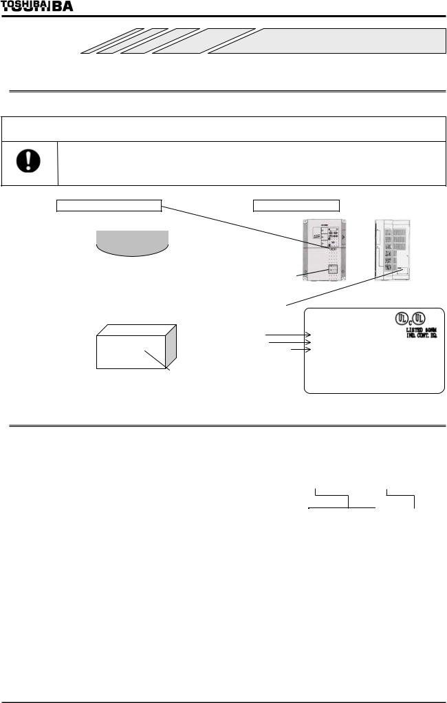
Make sure that the inverter delivered is exactly what you ordered.
 Warning
Use an inverter which matches the input power rating of your three-phase induction motor. The use of an inverter unsuitable for your motor can cause it to rotate in a wrong
Mandatory direction, and thus lead to grave accidents, including its burning due to overheating.
Applicable motor label Inverter main unit
Pet name |
|
200V-3.7kW |
|
|
|
|
|
|
|
||||||
|
|
|
|
|
|
|
|||||||||
Power supply |
|
|
|
|
|
|
Motor capacity |
|
|
|
|
|
|||
|
|
|
|
|
|
|
|
|
Warning label |
|
|
|
|
|
|
|
|
|
|
|
|
|
|
|
|
|
|
||||
Package |
Name plate |
|
|
|
|
|
|||||||||
|
|
|
|
|
|
|
|
|
|
|
|
|
|
|
|
|
|
|
|
|
|
|
|
|
Inverter type |
TRANSISTOR INVERTER |
|||||
|
|
|
|
|
|
|
|
|
TYPE-FORM |
|
VFA7-2037PL |
||||
|
|
|
|
|
|
|
|
|
Power supply |
SOURCE |
3PH 200-230V-50/60Hz |
||||
|
|
|
|
|
|
|
|
|
Rated output current |
OUTPUT |
3PH 200-230V |
||||
|
|
|
|
|
|
|
|
|
and capacity |
LOT No. |
0.01 80(400MAX)Hz 16.6A 6.5kVA |
||||
|
|
|
|
|
|
|
|
Type indication |
|
|
75 Cu wire |
||||
|
|
|
|
|
|
|
|
SERIAL No. |
|
|
|||||
|
|
|
|
|
|
|
|
|
|
||||||
|
|
|
|
|
|
|
|
|
|
|
M6587144P005 |
|
|
MADE IN JAPAN |
|
1.2 Contents of the product code
|
|
|
|
|
|
|
|
|
|
|
|
|
|
|
|
|
|
|
|
|
|
|
|
Special |
|||||
|
|
|
|
|
Type |
|
|
|
|
|
|
|
Form |
|
|
|
specification code |
||||||||||||
|
|
|
- |
|
|
|
|
|
|
|
|
|
|
||||||||||||||||
|
|
|
|
|
|
|
|
|
|
|
|
|
|
|
|
|
|
|
|
|
|
|
|
|
|
|
|
|
|
|
|
|
|
|
|
|
|
|
|
|
|
|
|
|
|
|
|
|
|
|
|
|
|
|
|
|
|
|
|
|
|
|
|
|
|
|
|
|
|
|
|
|
|
|
|
|
|
|
|
|
|
|
|
|
|
|
|
|
|
Model name |
|
Input voltage |
|
Applicable motor capacity |
|
Operating panel |
|
|
|
Additional |
|
|
|
Special |
|||||||||||||||
|
|
|
|
|
|
functions |
|
|
specification code |
||||||||||||||||||||
|
|
|
|
|
|
|
|
|
|
|
|
|
|
|
|
|
|
|
|
|
|
|
|
|
|||||
|
|
|
|
|
|
|
|
0 |
. 4kW :004 |
|
75kW :750 |
|
P :Provided |
|
|
F :External |
|
|
A□□ :Special |
||||||||||
TOSVERT |
|
2:200V 230V |
|
0. 75kW :007 |
|
90kW :900 |
|
P1 :Provided |
|
|
heat sink |
|
|
|
spec. code |
||||||||||||||
VF-A7 series |
|
4:380V 460V |
|
1. 5kW :015 |
110kW :110K |
|
(37kW and more) |
|
|
N :with dynamic |
|
|
(□□ is a |
||||||||||||||||
|
|
|
|
|
|
|
|
2 |
. 2kW :022 |
132kW :132K |
|
PL :Provided |
|
|
braking circuit |
|
|
number) |
|||||||||||
|
|
|
|
|
|
|
|
3 |
. 7kW :037 |
160kW :160K |
|
|
|
|
|
||||||||||||||
|
|
|
|
|
|
|
|
|
with noise filter |
|
|
NF :External |
|
|
|
|
|
||||||||||||
|
|
|
|
|
|
|
|
5 |
. 5kW :055 |
220kW :220K |
|
|
|
|
|
|
|
|
|||||||||||
|
|
|
|
|
|
|
|
|
|
|
|
|
|
|
heat sink |
|
|
|
|
|
|||||||||
|
|
|
|
|
|
|
|
7 |
. 5kW :075 |
280kW :280K |
|
|
|
|
|
|
|
|
|
|
|
|
|||||||
|
|
|
|
|
|
|
|
|
|
|
|
|
|
|
with dynamic |
|
|
|
|
|
|||||||||
|
|
|
|
|
|
|
|
11kW :110 |
|
|
|
|
|
|
|
|
|
|
|
|
|
|
|
||||||
|
|
|
|
|
|
|
|
|
|
|
|
|
|
|
|
|
|
braking circuit |
|
|
|
|
|
||||||
|
|
|
|
|
|
|
|
15kW :150 |
|
|
|
|
|
|
|
|
|
|
|
|
|
|
|
||||||
|
|
|
|
|
|
|
|
18 |
. 5kW :185 |
|
|
|
|
|
|
|
|
|
|
Y :Others |
|
|
|
|
|
||||
|
|
|
|
|
|
|
|
22kW :220 |
|
|
|
|
|
|
|
|
|
|
(non-standard) |
|
|
|
|
|
|||||
|
|
|
|
|
|
|
|
30kW :300 |
|
|
|
|
|
|
|
|
|
|
Z :Explosion proof |
|
|
|
|
|
|||||
|
|
|
|
|
|
|
|
37kW :370 |
|
|
|
|
|
|
|
|
|
|
|
|
|
|
|
|
|
|
|||
|
|
|
|
|
|
|
|
|
|
|
|
|
|
|
|
|
|
|
|
|
|
|
|
|
|
||||
|
|
|
|
|
|
|
|
45kW :450 |
|
|
|
|
|
|
|
|
|
|
|
|
|
|
|
|
|
|
|||
|
|
|
|
|
|
|
|
55kW :550 |
|
|
|
|
|
|
|
|
|
|
|
|
|
|
|
|
|
|
|||
Note) Turn off the power in advance when checking the rating of the inverter installed in a cabinet.
A-1

1.3 Names and functions
1.3.1 Panel description
VEC lamp |
RUN lamp |
MON lamp |
|
Lit when the Inverter |
Lit when the inverter is in |
Lit when the |
|
operation or blinks when It |
|||
is in vector control |
inverter is in |
||
is in auto acceleration/ |
|||
mode. |
monitor mode. |
||
deceleration mode. |
ECN lamp
Lit when the inverter is in energy-saving mode.
RUN key lamp
Lit when the RUN key is enabled.
RUN key
Pressing this key while the RUN key is lit starts the motor.
UP/DOWN key lam
With these keys, you can set the operation frequency while the UP/DOWN lamp is lit.
[ Front view ]
Connector for options
PRG lamp
Lit when the inverter is in parameter setting mode.
STOP key
Pressing this key while the RUN key lump is lit causes the motor to make a slowdown stop.
MONITOR key
Used to display the operation frequency, parameter setting error messages, etc.
ENTER key
DOWN key
UP key
CHARGE lamp
Indicates that a high voltage remains in the inverter. Do not open the terminal board cover for safety while this lamp is lit.
Cover for common serial option connectors
To use connectors reserved for options, detach this cover by sliding it to the right.
Parameter writer
Extension panel, etc.
Cover for serial RS485 connectors
To use an RS485 connector, detach this cover by sliding it to the right.(Refer to 2.3.3)
Used to install the following options:
Expansion TB option unit
Vector option unit
F10M option unit
S20 option unit
PG feed back board, etc.
Terminal board cover fixing screws
Optional board
Used to install the following options:
PG feedback options
Pushing mark, make this cover slide to the right.
Sink/source
switching
Terminal board cover
Be sure to attach the cover before starting the operation to prevent persons from touching the terminal board in error.
A-2
Warning label on the top (*1)
|
Connectors for optional |
|
Cooling fin |
|
|
|
|
|
add-on module/board |
|
|
Wiring hole (*2) |
|
Ventilation slits |
|
|
|
|
|
|
|
|
Rating label |
|
|
|
|
[Bottom view] |
[Side view] |
(*1) Peel off this label when the inverter is installed in a rather hot place. (Models for 15kW motor or smaller) (*2) Using scissors or a cutter, cut the rubber bush in the wiring hole as shown below.(Models for 22kW
motor or smaller)
Cut
Rubber bush
Panel indication
LED display is using the following signs to indicate the operation parameter and so on.
LED indication (number)
|
||||||||||
|
|
|
|
|
|
|
|
|
|
|
LED indication (alphabet)
|
||||||||||
|
|
|
|
|
|
|
|
|
|
|
|
||||||||
|
|
|
|
|
|
|
|
|
A-3
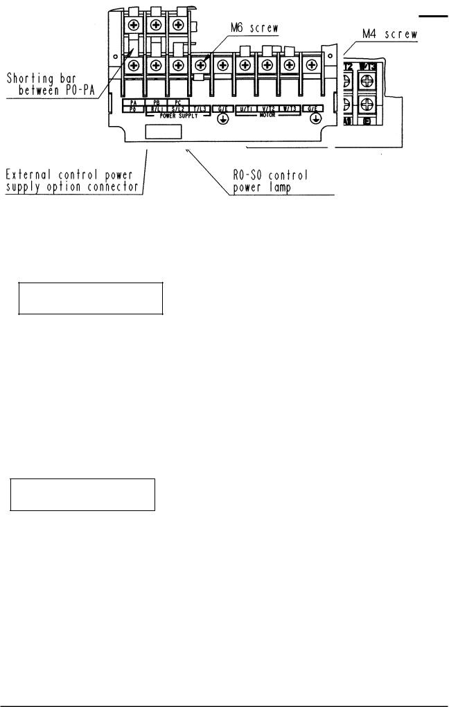
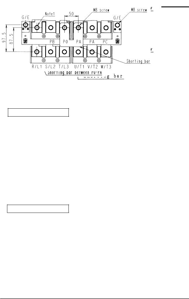
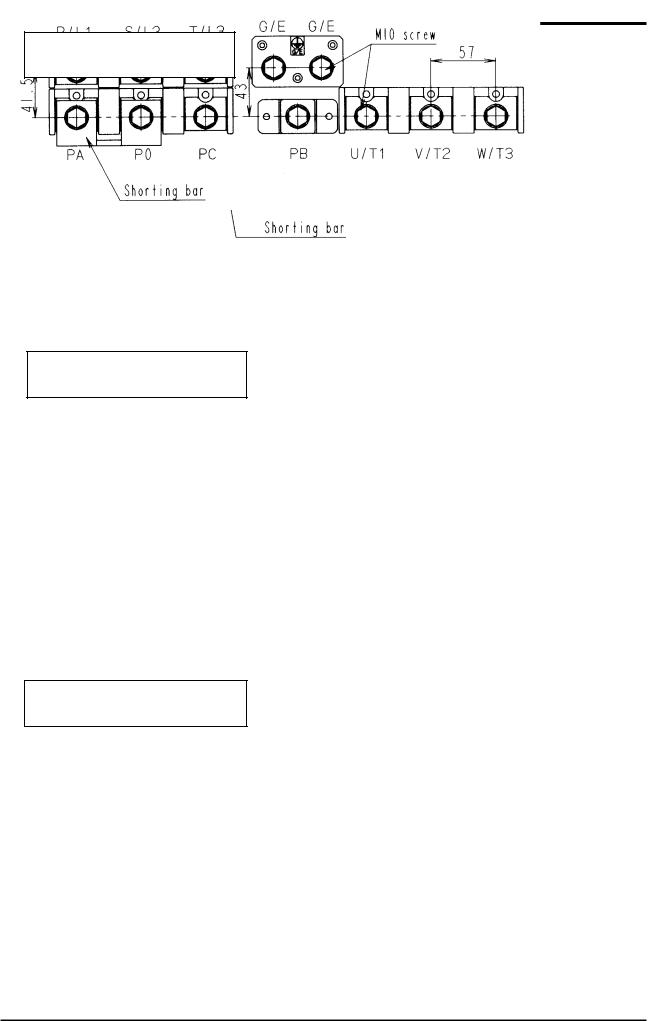
1.3.2 Main circuit, control power supply and control circuit terminal boards
Main circuit terminal board
VFA7-2004PL 2037PL
VFA7-4007PL 4037PL
VFA7-2055PL, 2075PL
VFA7-4055PL, 4075PL
VFA7-2110P 2150P
VFA7-4110PL 4150PL
A-4
VFA7-2185P, 2220P
VFA7-4185P, 4220P
Grounding terminal
VFA7-2300P, 4300P
VFA7-4370P1 4550P1
A-5
VFA7-2370P1 2550P1 VFA7-4750P1
VFA7-2750P1 VFA7-4110KP1, 4132KP1
VFA7-2900P1 VFA7-4160KP1 4280KP1
A-6
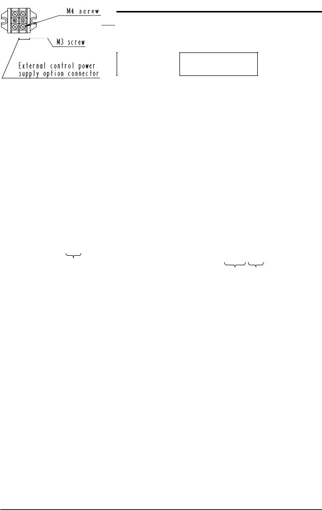
Control power supply terminal board
Note)To use R0,S0 terminal on 22kW model or smaller, you need a Control power supply
unit option.(Refer to 9.4)
VFA7-2055PL 2220P VFA7-4055PL 4220P
VFA7-2300P VFA7-4300P
VFA7-2370P1 2900P1 |
|
VFA7-4370P1 4280KP1 |
|
|
|
Control power |
|
|
supply inputs |
Control power |
Power supply |
|
supply inputs(*1) |
for control circuit |
(*1)Refer to 2.2 for the connection of control power cables by voltage(R46,R41 and S0 terminals).
A-7
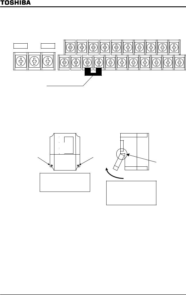
Control circuit terminal
The control circuit terminal board is common to all models.
|
RES |
|
S1 |
|
S2 |
|
S3 |
|
S4 |
|
RX |
|
AM |
|
FP |
OUT2 |
|
||||||||||
F |
|
R |
|
ST |
|
CC |
|
CC |
|
RR |
|
PP |
FM |
|
OUT1 |
P24 |
|||||||||||
FLA FLB FLC
ST-CC shorting bar |
Screw size M3 |
Refer to section 2.3.2 for the functions of terminals.
1.3.3 Detaching the terminal board front cover
Detach the front lower cover for wiring, following the steps below.
■Less than 22kW
|
|
Remove the two screws at the lower part of the front cover.
Hooked
To detach the cover, draw the terminal board cover toward you while swinging it up a little.
* For a 30kW model or larger, detach the whole front cover for wiring.
A-8


1.4 Notes on the application of inverters
1.4.1 Notes on motors combined with inverters
Keep in mind the following notes when using the VF-A7 in combination with a motor.
 Warning
Use an inverter which matches the input power rating of your three-phase induction motor. The use of an inverter unsuitable for your motor can cause it to rotate in a wrong direction,
Mandatory and thus lead to serious accidents, including its burning due to overheating.
Comparison with commercial power operation
The VF-A7 inverter uses a sinusoidal PWM control system. However, the waveforms of electric currents passing through the main and control circuits are not perfectly sinusoidal but slightly distorted though they are very close to perfect sine waves. For this reason, a motor produces more heat, larger noise and larger vibration when operated by means of the inverter than when operated directly by commercial power.
Operation in low speed ranges
Operating a general-purpose motor by means of the inverter causes a decrease in the cooling efficiency of the motor. So, reduce the motor's output below the rated load when operating it in a low speed range.
If you wish to operate a motor continuously at the rated torque, then use a Toshiba VF motor designed specially for use in conjunction with an inverter. When the inverter is combined with a VF motor, its overload protection level needs to be changed to "VF motor" ( setting).
Adjustment of overload protection level
The VF-A7 inverter has an overload detection circuit (electronic thermal detection) to protect the motor from overload. The reference current for the electronic thermal detection is set to the rated current of the inverter at the factory, and it needs to be adjusted to the rated current of the general-purpose motor combined with it.
High-speed operation at a frequency of 60 Hz or over
When a motor is operated at a frequency of 60 Hz or over, it produces larger noise and larger vibration, which can exceed a limit that the motor or its bearings can withstand. Contact the motor maker if you wish to operate the motor at such a high frequency.
Load of an oil lubrication type
When a speed reducer or a gear motor of an oil lubrication type is operated by the inverter, its oil lubrication efficiency decreases in low speed ranges. Inquire of the speed reducer maker about the allowable speed reduction range.
Extremely light load or load producing a very small moment of inertia
When a motor is operated under an extremely light load (e.g., at a load factor of less than 50%) or it drives a load which produces a very small moment of inertia, it sometimes becomes unstable, for example, it produces abnormal vibration or trips because of an over-current. In such a case, lower the carrier frequency to cope with this problem.
Unstable operation
When the inverter is used in combination with one of the following motors or loads, it sometimes makes the operation of the motor or load unstable.
A motor with a rated capacity that exceeds the motor capacity recommended for the inverter
A special type of motor, for example, an explosion-proof motor
When using the inverter for such motors, lower the inverter's carrier frequency to stabilize the operation. (In vector control mode, do not lower it below 2.2 kHz.)
A motor with a large backlash, which is coupled with a load
In this case, use the S-pattern acceleration/deceleration function, or in vector control mode, adjust the response time (setting of moment of inertia) or switch to V/f control mode to stabilize the operation.
A-9
A load, e.g., a reciprocating load, which requires a frequent change in the rotating speed
In this case, if the inverter is in vector control mode, adjust the response time (setting of moment of inertia) or switch to V/f control mode to stabilize the operation.
If it is operated in vector control mode, only a motor whose capacity is same as inverter standard or 1 rank lower is applied.
If it is operated in V/F (other than vector control), the rotating of motor can be unstable in combination with 3 or more ranks smaller motor.
<Stabilizing operation>
Lower the setting value of F300(PWM carrier frequency). (It causes much magnetic noise of motor, but it is not abnormal.)
In the case that it is still unstable even if the carrier frequency is lowered to 2.2kHz at ( ), set the setting value of F489(Dead time compensation) to 1 (Disabled) .
Braking of a motor after power shutoff
If the power is shut off while the motor is still rotating, the motor keeps rotating (or coasting) for a while before it comes to a complete stop. If you wish to stop it soon after turning off the power, equip the motor with an auxiliary braking system. There are several types of braking systems available, for example, mechanical and electrical types. Select a braking system which matches your system.
Load producing negative torque
When the inverter is combined with a load producing negative torque, the over-voltage or over-current protective function of the inverter sometimes works and causes the motor to trip. In this case, it is necessary to install a dynamic braking resistor, etc., suitable for the load.
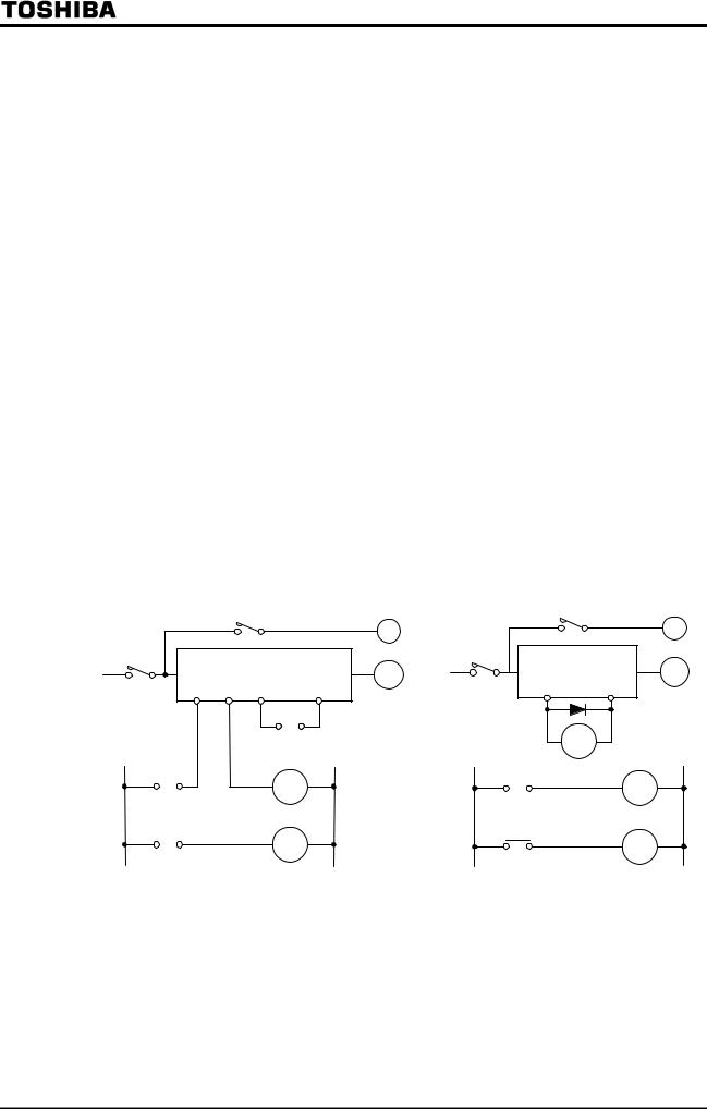
Motor with a braking system
When a brake-equipped motor is connected directly with the inverter, the brake cannot be released at start-up because of an insufficient voltage. To avoid this, connect the brake cables separately from the motor main cables.
|
(Non-exciting brake) |
(Non-exciting brake) |
||
|
MC2 |
|
MC2 |
|
|
|
B |
|
B |
MC1 |
|
|
MC1 |
IM |
|
FLB FLC ST |
IM |
Three-phase OUT1 |
|
Three-phase |
CC |
P24 |
||
|
|
power supply |
|
|
power supply |
|
MC3 |
|
|
|
|
|
||
|
|
|
|
LOW |
|
MC1 |
MC3 |
LOW |
MC3 |
|
|
|
||
|
MC3 |
MC2 |
MC3 |
MC2 |
|
|
|||
|
|
|
||
Circuit configuration 1 Circuit configuration 2
In circuit configuration 1, the brake is turned on and off by means of MC2 and MC3. If the circuit is configured differently, the motor can trip because of a locked rotor current produced during braking.
In circuit configuration 2, the brake is turned on and off by means of a low-speed signal OUT1. However, for certain applications, e.g., elevator applications, it is recommended to use a low-speed detection signal (function of terminal OUT1) to turn on and off the motor. Contact your Toshiba dealer before designing a system.
A-10
1.4.2 Notes on inverters
Over-current protective function
The inverter has an over-current protective function. The current for this protection is adjusted to the maximum current rating of the applicable motors by default. Therefore, when the inverter is used to control a motor with a relatively small capacity, it is necessary to readjust the over-current protection level and the electronic thermal protective function. In such a case, follow the procedure specified in 5.13 to readjust them.
Inverter capacity
An inverter with a small capacity (kVA) must not be used for a motor with a relatively large capacity even if the motor is operated under a small load. If an inverter is used this way, the output peak current rises high because of a current ripple, thus causing the motor to trip easily.
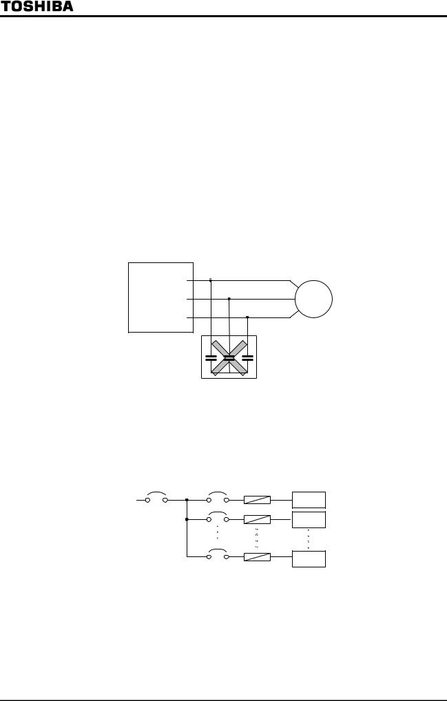
Power factor improving capacitor
No power factor improving capacitor should be connected on the output side of the inverter. When the inverter is used for a motor equipped with a capacitor for power factor improvement, remove the capacitor from the motor. Connecting such a capacitor causes the inverter to break down and the motor to trip, or breaks the capacitor itself.
U
Inverter
V 
W
IM
Remove the power factor improving capacitor and the surge absorber, if any.
Power factor improving capacitor
Use of an inverter at a voltage other than the rated one
There is a need to connect it to a power unit supplying a voltage different from the rated voltage, increase or reduce the supply voltage to the inverter's rated voltage, using a transformer, etc.
Use of a set of inverters, which requires circuit-breaking devices
MCCB1 |
MCCB2 Breaking fuse) |
|
INV1 |
|
MCCB3 |
|
INV2 |
|
MCCBn |
INVn
Circuit-breaking of defective inverter
When two or more inverters are connected to the same power line as shown above, it is necessary to select a circuit-breaking characteristic ensuring that, for example, if a short circuit occurs in INV 1, only MCCB2 trips but not MCCB1. If it is difficult to select a proper characteristic, then insert a breaking fuse between MCCB2 and INV 1 in this case.
■Note on the disposal of inverters
Be sure to dispose of inverters as industrial wastes, when they become unnecessary.
A-11

1.4.3 Influences of leakage currents and measures against it
Warning
An electric current can leak through an input or output cable of the inverter because of its insufficient capacitance and, sometimes, affects the peripheral systems. The amount of a leakage current depends on the carrier frequency, the length of the input/output cable, etc. It is advisable to take the following measures to prevent leakage currents.
(1) Influences of a current leaking into other systems via the ground
An electric current can leak not only into other circuits of an inverter but also into other inverters through grounding wires. Such a leakage current can exerts influences on various electronic devices, for example, malfunction of ground leakage breakers or relays, ground relays, fire alarms, sensors, etc., noise on CRTs and display of incorrect current values on a
CRT screen.
Power |
Inverter |
IM |
|
supply |
|||
|
|
Inverter  IM
IM
Measures to be taken:
1.Lower the PWM carrier frequency.
Use parameter to lower the PWM carrier frequency.
2.Use high frequency-ready ground leakage breakers (e.g., Esper Mighty series(manufactured by Toshiba Schneider Electric Ltd.)). When these ground leakage breakers are installed, there is no need to lower the PWM carrier frequency.
3.If sensors and CRTs are affected, they can be restored by lowering the PWM carrier frequency as described in 1 above. However, if lowering the PWM carrier frequency results in an increase in magnetic noise, contact your Toshiba dealer.
Cautions for applying models with a built-in noise filter.
For the models with a built-in noise filer, the leakage current value at power supply of (delta) connecting wire (1 phase earth) can be larger than normal inverter, so be
careful.
<Standard leakage current value> VFA7-2004PL 2037PL : about 4mA VFA7-2055PL, 2075PL : about 13mA
(2)Influences of a current leaking from a cable into other cables
Thermal relay
If a current leaks from an output cable of an inverter to other cables because of its insufficient capacitance, the high-frequency elements of the leakage current sometimes increase the effective current value, and thus cause external relays to malfunction. For a model with relatively long cables (longer than 50 m) or a model designed for motors with small current ratings (several amperes), especially 400V model with a small capacity (3.7kW or less), the external thermal relays can malfunction more easily because a leakage current can be too large as compared with the current rating of the motor.
A-12
Power |
Inverter |
IM |
|
supply |
|||
|
|
A
Measures to be taken:
1.Use the electronic thermal function provided for the inverter.
Use parameter , to set the electronic thermal function.
2.Lower the PWM carrier frequency, though this results in an increase in motor magnetic noise. Use parameter to lower the PWM carrier frequency.
3.For improvement, connect film capacitors with capacitance of 0.1 to 0.5μF-1000V to the input and output terminals in each phase of the each thermal relay.
U/T1 |
|
V/T2 |
IM |
W/T3 |
|
CT and ammeter
When a CT and an ammeter are installed externally to monitor the output current of the inverter, the ammeter could be burned by the high-frequency elements of a leakage current. For a model with relatively long cables (longer than 50 m) or a model for motors with small current ratings (several amperes), especially 400V model with a small capacity (3.7kW or less), the ammeter can be burned more easily by the high-frequency elements of a leakage current which flows into it through the external CT because a leakage current can be too large as compared with the current rating of the motor.
Measures to be taken:
1. For external meters, use the meter output terminals in the inverter's control circuit.
Output currents can also be output to the meter output terminals (AM). Use a 1 mAdc fullscale ammeter or a 7.5 Vdc-1 mA full-scale voltmeter.
2. Use the monitor function provided for the inverter.
Use the monitor function provided for the inverter to check the output current.
A-13
1.4.4 Notes on installation
■Installation environment
The VF-A7 inverter is an electronic control device. Therefore, due consideration should be given to its installation environment.
 Danger
-Do not put any inflammable material near the inverter, or it could catch a fire if the inverter sparks because of trouble.
Prohibited
-Use the inverter under environmental conditions specified by this instruction manual, or it could break down.
Mandatory
Warning
-Do not install the inverter in any place subject to vibration, or it could fall and cause injury to persons.
Prohibited
Make sure that the supply voltage is within +10%/-15% (within ±10% during continuous operation under full load) of the inverter's rated voltage specified on its
rating label.
Mandatory Supplying a voltage exceeding the above range could lead to a breakdown, an electric shock or a fire.
A-14

Avoid installing the inverter in a hot, damp, or dusty place, a place subject to freezing or water splash, or a place full of metal chips.
Do not install the inverter where there are gases that corrode metal or solvents that adversely affect plastic.
Use the inverter at ambient temperatures of -10 to 40 (-10 to 50 for models designed for 18.5kW motors or larger).
Measuring position
Measuring position
Note) The inverter produces heat. When installing it in a cabinet, consider its ventilating condition and internal space. When an inverter for 15kW motors or smaller is installed in a cabinet, it is advisable to peel off the label on the top of the inverter. Models for 18.5kW motors or larger can be used at ambient temperatures of up to 50 . (These models have no label on their top.)
Do not install the inverter in any place subject to vibration.
Note) If you intend to install it in a place subject to vibration, you should take measures to protect it from vibration. In such a case, contact your Toshiba dealer in advance.
If installing the inverter close to any of the following appliances or devices, take necessary measures to prevent them from malfunctioning.
Solenoid ... Connect a surge suppressor to the coil. Brake ... Connect a surge suppressor to the coil.
Magnetic contactor ... Connect a surge suppressor to the coil.
Fluorescent lamp ... Connect a surge suppressor to the coil. Resistor ... Move it away from the inverter.
Resistor
A-15
■Installation
Danger
|
- Do not install or operate the inverter if it is damaged or any part is missing from it. |
|
|
Operating the inverter in a defective condition could lead to a shock or a fire. |
|
Prohibited |
Request your Toshiba dealer for repair. |
|
|
||
|
- Install the inverter on a non-combustible board, such as a steel plate. Installing it |
|
|
on an inflammable wall or board could lead to a fire because its back is heated up |
|
|
during operation. |
|
Mandatory |
- Do not use the inverter with the front cover detached, or it could cause a shock. |
|
- Install an emergency shutdown device which matches the system (for example, a |
||
|
||
|
switch interlocked with the brake of the machine). Failure to do so could lead to |
|
|
injury to persons since it has no emergency stop function. |
|
|
- Do not use any optional devices other than those designated by Toshiba. The use |
|
|
of improper devices could lead to accidents. |
 Warning
-Install the main unit on a wall, or the like, which is strong enough to withstand its weight, or it could fall and cause injury to persons.
-Install a mechanical brake whenever the motor requires a brake (device which
Prohibited |
retains the motor shaft). Failure to do so could lead to injury to persons because |
|
the inverter itself has no function of mechanically retaining the brake shaft. |
||
|
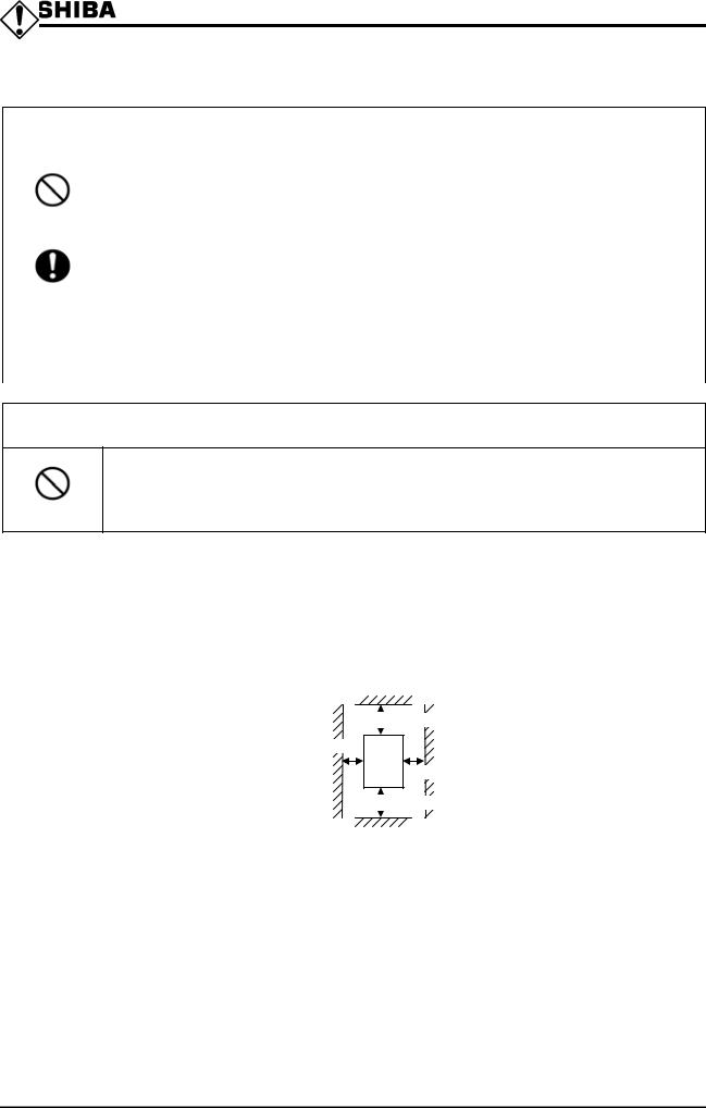
■Installation place
Install the inverter vertically on a flat steel wall in a well-ventilated place. When installing two or more inverters, leave a clearance of at least 10 cm between inverters placed side by side.
 above 10cm
above 5cm
above 5cm
 above 10cm
The clearances indicated above are minimum clearances to be secured. Every air-cooling type model is equipped with a cooling fan. For this type of inverter, therefore, leave as large clearances as possible above and under the inverter.
For a model designed for 37kW motors or larger, leave a clearance of at least 20 cm above and under it for easy installation of wires and possible replacement of the fan.
Note) Do not install the inverter in a hot, damp, or dusty place, or a place full of metal chips. When you intend to install in a critical environment, consult your Toshiba dealer in advance.
A-16

■Calorific values of inverters and amount of air to be ventilated
The VF-A7 series of inverter loses about 5% of energy when switching electric currents from AC, DC, then to AC. To limit a temperature rise due to this energy loss, it is necessary to forcefully ventilate and cool down the cabinet in which the inverter is installed.
The table below lists the amounts of air to be ventilated forcefully and the heat radiation areas required for closed-type cabinets containing an inverter.
Voltage |
Applicable |
Calorific value |
Amount of air to be |
Heat radiation area |
required |
|
motor |
of inverter |
ventilated forcefully |
for closed-type |
cabinet |
||
class |
||||||
(kW) |
(W) |
(m3/min.) |
(m2) |
|
||
|
|
|||||
|
0.4 |
50 |
0.29 |
1.0 |
|
|
|
0.75 |
70 |
0.40 |
1.4 |
|
|
|
1.5 |
110 |
0.63 |
2.2 |
|
|
|
2.2 |
140 |
0.80 |
2.8 |
|
|
|
3.7 |
220 |
1.3 |
4.4 |
|
|
|
5.5 |
310 |
1.8 |
6.2 |
|
|
|
7.5 |
420 |
2.4 |
8.4 |
|
|
200V |
11 |
580 |
3.3 |
11.6 |
|
|
15 |
770 |
4.4 |
15.4 |
|
||
|
18.5 |
940 |
5.4 |
18.8 |
|
|
|
22 |
1110 |
6.3 |
22.2 |
|
|
|
30 |
1490 |
8.5 |
29.8 |
|
|
|
37 |
1530 |
8.7 |
30.6 |
|
|
|
45 |
1850 |
10.5 |
37.0 |
|
|
|
55 |
2250 |
12.8 |
45.0 |
|
|
|
75 |
3050 |
17.4 |
61.0 |
|
|
|
90 |
3650 |
20.8 |
73.0 |
|
|
|
0.75 |
70 |
0.40 |
1.4 |
|
|
|
1.5 |
110 |
0.63 |
2.2 |
|
|
|
2.2 |
140 |
0.80 |
2.8 |
|
|
|
3.7 |
220 |
1.3 |
4.4 |
|
|
|
5.5 |
280 |
1.6 |
5.6 |
|
|
|
7.5 |
370 |
2.1 |
7.4 |
|
|
|
11 |
530 |
3.0 |
10.6 |
|
|
|
15 |
710 |
4.0 |
14.2 |
|
|
|
18.5 |
800 |
4.6 |
16.0 |
|
|
400V |
22 |
940 |
5.4 |
18.8 |
|
|
30 |
1270 |
7.2 |
25.4 |
|
||
|
37 |
1270 |
7.2 |
25.4 |
|
|
|
45 |
1490 |
8.5 |
29.8 |
|
|
|
55 |
1810 |
10.3 |
36.2 |
|
|
|
75 |
2300 |
13.1 |
46.0 |
|
|
|
90 |
2750 |
15.7 |
55.0 |
|
|
|
110 |
3350 |
19.1 |
67.0 |
|
|
|
132 |
4010 |
22.9 |
80.2 |
|
|
|
160 |
4850 |
27.6 |
97.0 |
|
|
|
220 |
6650 |
37.9 |
133.0 |
|
|
|
280 |
8450 |
48.2 |
169.0 |
|
Note)The calorific values in the above table do not include those of optional external devices (such as input reactors, DC reactors and radio noise filters).
A-17
■Control panel designed in consideration of possible influences of noise
Inverters produce high-frequency noise. To avoid influences of noise, measures must be taken in designing a control panel. Here are some examples of measures against noise.
Separately install the wires of the main circuit and those of the control circuit. Do not install their wires in the same duct or in parallel with each other, and do not bind them together.
Use shielded wires or twisted wires for the control circuit.
Separate the input wires (on power supply side) of the main circuit from the output wires (on motor side). Do not install them in the same duct or in parallel with each other, and do not bind them together.
Be sure to ground the grounding terminal (G/E) of the inverter.
Be sure to connect a surge suppressor to every electromagnetic contactor and every relay installed near the inverter.
Install noise filters, as required.
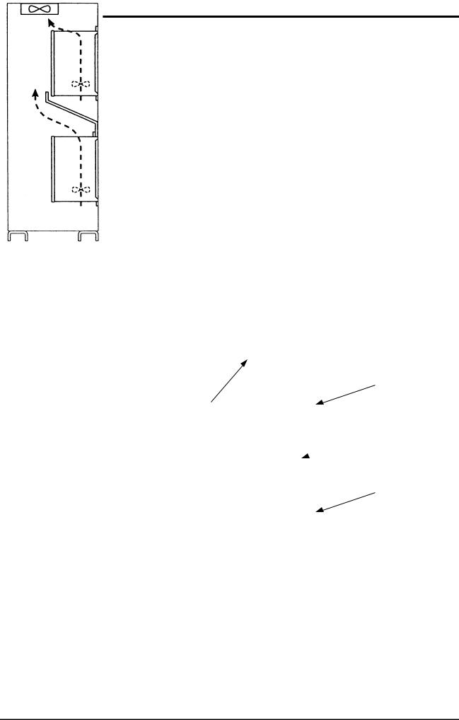
■Notes on the installation of two or more inverters in a single cabinet
When installing two or more inverters in a single cabinet, take the following precautions:
Leave a clearance of at least 10 cm between inverters placed side by side.
Leave a clearance of at least 20 cm between inverters placed one above another.
Install a deflector, etc., to prevent the upper inverter from being affected by heat produced and being exhausted by the lower one.
Inverter
Cooling fun
 Deflector
Inverter
Installation of Cooling fun
A-18
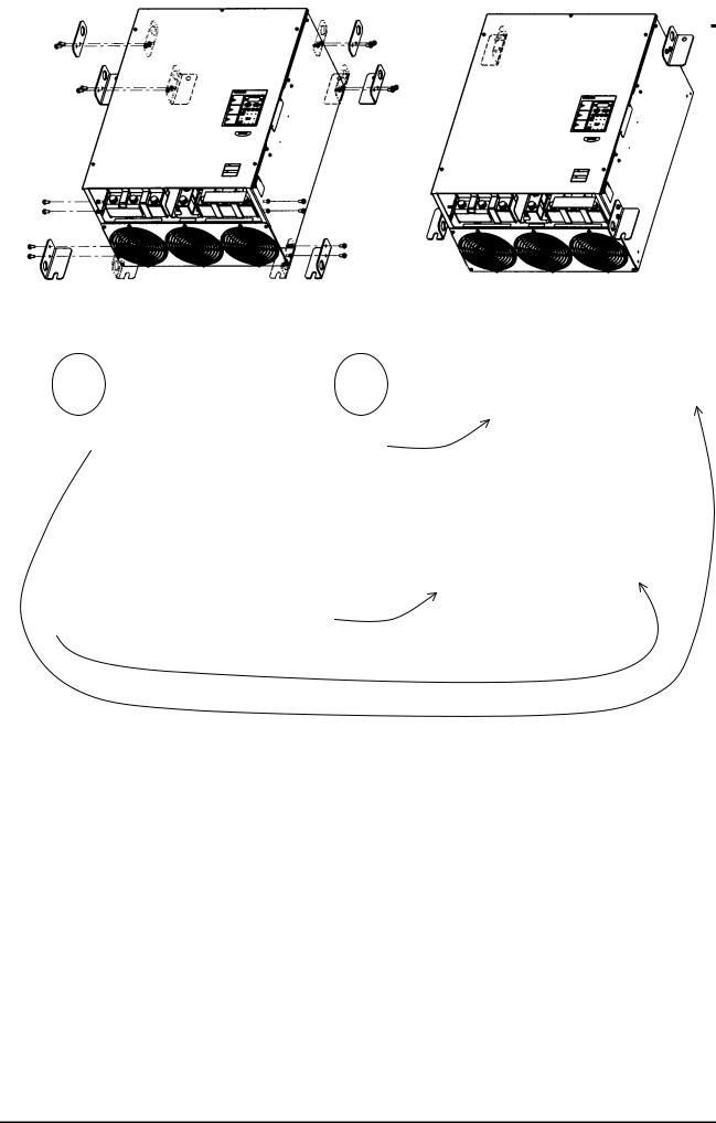
■Heat-sink going out attachment(simple type)
To install a standard VF-A7 designed for 37kW motor or larger, you can choose a one from next two forms.
(1)Normal attachment (Whole the inverter is in the cabinet)
(2)Heat-sink going out (the cabinet) attachment(simple type)
Heat-sink going out attachment reduces the generation of heat inside the cabinet. When you carry out heat-sink going out attachment, please change the position of the attachment ornaments (hanging hole) of the inverter according to the following figure.
(1) Normal attachment |
(2) Heat-sink going out attachment |
|
(simple type) |
Take this ornament |
Take this ornament |
off (*1) |
off (*1) |
Change the position
Change the position
Change the position
Change the position
(*1) Metallic ornaments with the hanging hole are attached only in the following models.
200V class: Applicable motor capacity is 75kW or larger
400V class: Applicable motor capacity is 110kW or larger
A-19

2. Connection 
 Danger
Never disassemble, modify or repair the inverter. Its disassembly could cause an
electric shock, a fire or an injury. Request your Toshiba dealer for repair.
Disassemble
Do not put or insert anything (e.g., an electric cable, a bar or a steel wire) into the inverter, or the inverter could cause a shock or a fire.
Prohibited Do not splash water over the inverter, or the inverter could cause a shock or a fire.
 Warning
Do not hold the front cover to carry the inverter, or the cover could come off and
cause the main unit to fall, thus causing you to get an injury.
Prohibited
For models designed for 30kW motor or larger, carry it at least in a twosome, or it
could fall and cause you to get an injury.
Mandatory
2.1 Cautions as to wiring
 Danger
|
Never open the front cover of the inverter (or the door of the cabinet in which the |
|
inverter is installed) when the inverter is energized, or you could get a shock since a |
Prohibited |
high voltage is applied to certain portions of it. |
|
Do not turn on the power before attaching the front cover (or closing the door of the cabinet if the inverter is installed in it). Turning on the power with the cover or the
door left opened could lead to an electric shock.
Mandatory Entrust all electrical work to an experienced specialist. Wiring by an inexperienced person could result in a fire or an electric shock.
Connect the output terminals (on the motor side) correctly. connection of the terminals causes the motor to rotate in a wrong direction, and thus could result in injury to persons.
Perform wiring always after installing the inverter, or you could get a shock or an injury.
Be sure to perform the following preparatory work before proceeding to wiring.
(1)Turn off the power.
(2)Wait more than 10 minutes, and make sure that the charge lamp is extinct.
(3)Using a circuit tester with a D.C. voltage measuring capacity of more than 800 V, check to be sure that the voltage remaining in the D.C. main circuit (between PA and PC) is below 45 V to do so could lead to an electric shock.
Tighten the terminal board fixing screws at the specified torque. Failure to do so could lead to a fire.
Connect grounding wires correctly and securely. Failure to do so could cause an electric shock or a fire if current leakage occurs or the inverter breaks down.
Be Grounded
B-1
|
|
|
Warning |
|
|
Do not connect any device or unit with a built-in capacitor (noise filter, surge |
|
|
|
suppressor, etc.) to output terminals (on the motor side), or it could cause the risk of |
|
|
Prohibited |
a fire. |
|
■Prevention of radio noise
Prevent interference, such as radio noise, separately install and bind cables connected to the power supply-side terminals (R/L1, S/L2 and T/L3) of the main circuit and those connected to the motor-side terminals (U/T1, V/T2 andW/T3).
■Power supply to the control and main circuits (for the 22kW and smaller models)
You want to keep the control circuit alive when the main circuit shuts off because of trouble or tripping, you can use an optional power supply unit to supply power to the control circuit separately from the main circuit.
■Notes on wiring
When connecting wires to the main circuit terminals, use crimp contacts because there is no large space between terminals, and attach them in order so that they do not come into contact with each other.
Be sure to ground the inverter by connecting wires of the following size or larger to the grounding terminal G/E.(UL standard)
|
|
Voltage |
|
Applicable motor |
|
Grounding wire size |
|
|
|
class |
|
|
AWG(cross-section[mm2]) |
|
|
|
|
|
|
|
|
||
|
|
|
|
0.4 5.5kW |
|
12(3.5) |
|
|
|
|
|
7.5kW |
|
10(5.5) |
|
|
|
|
|
11 15kW |
|
6(14) |
|
|
|
200V |
|
18.5 22kW |
|
4(22) |
|
|
|
|
|
30 37kW |
|
2(38) |
|
|
|
|
|
45 55kW |
|
2/0(60) |
|
|
|
|
|
75 90kW |
|
4/0(100) |
|
|
|
|
|
0.75 11kW |
|
12(3.5) |
|
|
|
|
|
15kW |
|
10(5.5) |
|
|
|
|
|
18.5kW |
|
8(8) |
|
|
|
|
|
22 30kW |
|
6(14) |
|
|
|
400V |
|
37 55kW |
|
4(22) |
|
|
|
|
|
75kW |
|
2(38) |
|
|
|
|
|
110 132kW |
|
2/0(60) |
|
|
|
|
|
160 220kW |
|
4/0(100) |
|
|
|
|
|
280kW |
|
300(150) |
|
|
|
|
|
||||
Refer to the |
table in 9.1 for wire |
sizes. |
|||||
For the 200V 0.4~7.5kW models and the 400V 0.75~7.5kW models, a grounding screw (M5) is provided in the wiring hole cover, in addition to a grounding terminal.
Wire sizes listed in 9.1 is for the case the wire length is below 30m. To use wires longer than 30m, you need larger cables than listed in 9.1.
Tighten a terminal stand screw with specified bolting torque.
Recommended bolting torque for terminal stand
|
|
N m |
lb ins |
|
|
M3 |
0.5 |
4.4 |
|
|
M4 |
1.2 |
11 |
|
|
M5 |
2.4 |
21 |
|
|
M6 |
4.0 |
35 |
|
|
M8 |
8.0 |
71 |
|
|
M10 |
16 |
142 |
|
|
M12 |
32 |
283 |
|
|
|
|
|
|
|
|
B-2 |
|
|
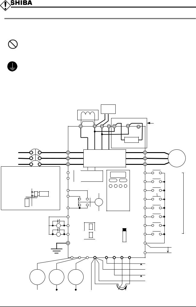
2.2 Standard connection
|
|
Danger |
|
|
-Do not connect the power cables to any output terminal (U/T1, V/T2 or W/T3 on the |
|
|
|
motor side), or the inverter could break down and cause a fire. |
|
|
Prohibited |
-Do not connect a resistor to any D.C. terminal (between PA and PC or PO and PC), or |
|
|
the inverter could cause a fire. |
|
|
|
|
To install external braking resistor, refer to 6.13.4. |
|
|
|
-Connect grounding wires correctly and securely. Failure to do so could cause an |
|
|
|
electric shock or a fire if current leakage occurs or the inverter breaks down. |
|
|
Be Grounded |
|
|
|
[Standard connection diagram for sink logic(minus common)] |
|||
200V class: 0.4 22kW |
|
|
|
400V class: 0.75 22kW |
* External braking resistor Refer to 6.13.4 for details |
||
|
DC reactor (DCL) |
When using an external braking resistor in 3.7kW |
|
|
model or less, change the connection of the internal |
||
|
*2 (Optional) |
||
|
resistor from terminal PB1 to terminal PR1. |
||
Main circuit power supply
200V |
class 0.4 7.5kW |
|
|
|
|
|
|
This circuit is provided |
3-phase 200 230V-50/60Hz |
|
|
|
|
|
|
||
200V |
class 11 22kW |
PO |
PA |
PB |
PC |
(PA1)(PB1) |
|
only for the 3.7kW and |
3-phase 200 220V-50Hz |
(PR1) |
smaller models. |
||||||
3-phase 200 230V-60Hz |
|
|
|
|
|
|
|
|
400V |
class 0.75 22kW |
|
|
|
|
|
|
|
3-phase 380 460V-50/60Hz |
|
|
|
|
|
|
|
|
|
MCCB |
R/L1 |
|
|
Built-in dynamic |
braking resistor |
Motor |
|
|
|
|
|
|
U/T1 |
|
|
|||
|
|
|
|
|
|
|
|||
|
|
S/L2 |
|
Main circuit |
V/T2 |
IM |
|
||
|
|
T/L3 |
|
W/T3 |
|
||||
|
|
|
|
|
|
|
|||
*When using a separate power source |
|
R0 |
Control |
|
|
F |
Forward |
|
|
for the control |
circuit |
|
CN21 |
|
|
|
|||
For the 22kW and smaller models, |
|
circuit |
|
|
|
|
|
||
|
S0 |
|
|
R |
Reverse |
|
|||
power is supplied to the control circuit |
|
|
|
|
|
||||
from the main circuit. An optional device |
FLA |
|
|
|
|
|
|
||
is required to |
CN21 |
|
|
|
|
ST |
Standby |
|
|
supply from |
|
FLB |
|
|
|
|
|||
|
|
|
|
|
|
||||
another source. |
|
|
|
|
RES |
Reset |
|
||
(though |
Control circuit |
|
|
FL |
|
Factory |
|||
terminals only |
Option |
|
FLC |
|
|
|
|||
are provided.) |
|
|
|
|
S1 |
Preset |
default |
||
|
|
|
|
|
|||||
*1: The control |
power supply terminals |
|
|
|
Control panel |
|
speed 1 |
settings |
|
|
|
|
|
Preset |
|||||
|
P24 |
|
S2 |
|
|||||
RO and SO are optionally |
|
|
|
|
speed 2 |
|
|||
|
|
|
|
|
|
|
|||
available for the 22kW and |
Ry |
OUT1 |
|
Connector for |
|
S3 |
Preset |
|
|
smaller models. Though terminals |
|
common serial |
|
|
|||||
RO and SO are fitted as |
|
|
|
communication |
SINK |
|
speed 3 |
|
|
|
|
|
|
Preset |
|
||||
|
OUT2 |
|
RS485 connector |
S4 |
|
||||
standard for the 22kW and |
Ry |
|
|
|
|||||
smaller models as well, they |
|
|
|
for serial |
SOURCE |
speed 4 |
|
||
|
G/E |
|
communication |
|
|
||||
are not connected internally. |
|
|
|
CC |
Common |
|
|||
|
|
|
|
|
|
||||
*2: The inverter is shipped with |
|
|
|
|
|
|
|
|
|
the terminals PO and PA |
FP FM AM CC |
RX |
VI |
RR |
PP |
|
Current signal |
shorted with a bar. Remove |
4 to 20mA |
||||||
this shorting bar when installing |
|
|
|
|
|
|
|
a DC reactor (DCL).
|
|
|
|
Voltage signal -10 +10V |
|
Digital |
Frequency |
Ammeter |
|
|
|
voltmeter |
meter |
|
|
Voltage signal 0 10V |
|
|
|
|
|
|
|
|
|
|
|
External potentiometer |
|
|
|
Voltmeter or ammeter |
|||
|
|
(or voltage signal between RR and CC: 0 10V) |
|||
B-3
 Loading...