


MW27H62
SERVICE MANUAL
DOCUMENT CREATED IN JAPAN, April, 2006 GREEN
COLOR TELEVISION/
VIDEO CASSETTE RECORDER
/
DVD VIDEO PLAYER
MW27H62
FILE NO. 810-200657GR
The above model is classified as a green product (*1), as indicated by the underlined serial number.
This Service Manual describes replacement parts for the green product. When repairing this green
product, use the part(s) described in this manual and lead-free solder (*2).
For (*1) and (*2), see the next page.
REV.01

(*1) GREEN PRODUCT PROCUREMENT
The EC is actively promoting the WEEE & RoHS Directives that define standards for recycling
and reuse of Waste Electrical and Electronic Equipment and for the Restriction of the use of
certain Hazardous Substances. From July 1, 2006, the RoHS Directive will prohibit any
marketing of new products containing the restricted substances.
Increasing attention is given to issues related to the global environmental. Toshiba Corporation
recognizes environmental protection as a key management tasks, and is doing its utmost to
enhance and improve the quality and scope of its environmental activities. In line with this,
Toshiba proactively promotes Green Procurement, and seeks to purchase and use products,
parts and materials that have low environmental impacts.
Green procurement of parts is not only confined to manufacture. The same green parts used in
manufacture must also be used as replacement parts.
(*2) LEAD-FREE SOLDER
This product is manufactured using lead-free solder as a part of a movement within the consumer
products industry at large to be environmentally responsible. Lead-free solder must be used in
the servicing and repair of this product.
WARNING
This product is manufactured using lead free solder .
DO NOT USE LEAD BASED SOLDER TO REPAIR THIS PRODUCT !
The melting temperature of lead-free solder is higher than that of leaded solder by 86°F to 104°F
(30°C to 40°C). Use of a soldering iron designed for lead-based solders to repair product made
with lead-free solder may result in damage to the component and or PCB being soldered. Great
care should be made to ensure high-quality soldering when servicing this product ⎯ especially
when soldering large components, through-hole pins, and on PCBs ⎯ as the level of heat
required to melt lead-free solder is high.
A1-1
A1-2
PREPARATION OF SERVICING
The laser diode used for a pickup head may be destroyed with external static electricity.
Moreover, even if it is operating normally after repair, when static electricity discharge is received at the
time of repair, the life of the product may be shortened.
Please perform the following measure against static electricity, be careful of destruction of a laser diode
at the time of repair.
• Place the unit on a workstation equipped to protect against static electricity, such as conductive mat.
• Soldering iron with ground wire or ceramic type is used.
• A worker needs to use a ground conductive wrist strap for body.
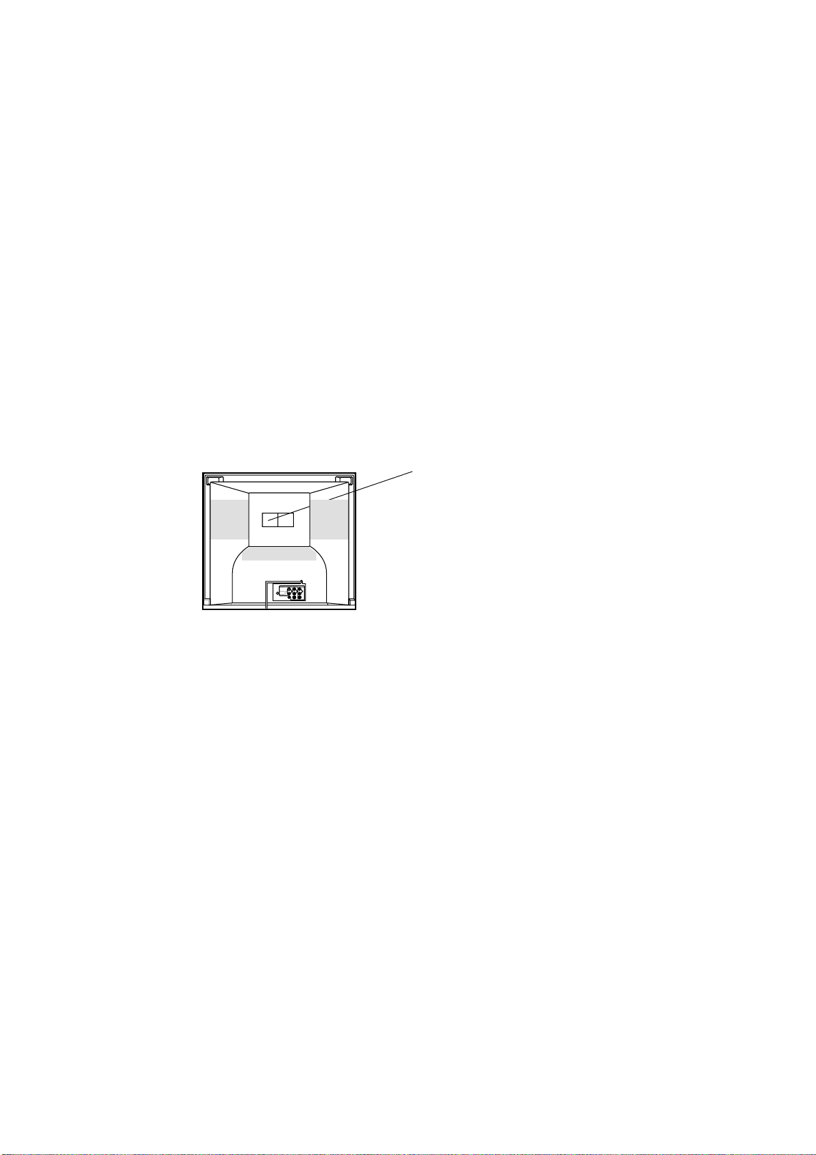
Location of the required Marking
The rating sheet and the safety caution are on the rear of the unit.
CERTIFICATION: COMPLIES WITH FDA
RADIATION PERFORMANCE STANDARDS,
21 CFR SUBCHAPTER J.
CAUTION
THIS DIGITAL VIDEO PLAYER EMPLOYS A LASER SYSTEM.
TO ENSURE PROPER USE OF THIS PRODUCT, PLEASE READ THIS SERVICE MANUAL CARE-
FULLY AND RETAIN FOR FUTURE REFERENCE. SHOULD THE UNIT REQUIRE MAINTENANCE,
CONTACT AN AUTHORIZED SERVICE LOCATION-SEE SERVICE PROCEDURE.
USE OF CONTROLS, ADJUSTMENTS OR THE PERFORMANCE OF PROCEDURES OTHER THAN
THOSE SPECIFIED HEREIN MAY RESULT IN HAZARDOUS RADIATION EXPOSURE.
TO PREVENT DIRECT EXPOSURE TO LASER BEAM, DO NOT TRY TO OPEN THE ENCLOSURE.
VISIBLE LASER RADIATION MAY BE PRESENT WHEN THE ENCLOSURE IS OPENED. DO NOT
STARE INTO BEAM.
A1-3
SERVICING NOTICES ON CHECKING
6. AVOID AN X-RAY1. KEEP THE NOTICES
As for the places which need special attentions,
they are indicated with the labels or seals on the
cabinet, chassis and parts. Make sure to keep the
indications and notices in the operation manual.
3. USE THE DESIGNATED PARTS
5. TAKE CARE TO DEAL WITH THE
CATHODE-RAY TUBE
In the condition that an explosion-proof cathode-
ray tube is set in this equipment, safety is
secured against implosion. However, when
removing it or serving from backward, it is
dangerous to give a shock. Take enough care to
deal with it.
Safety is secured against an X-ray by consider-
ing about the cathode-ray tube and the high
voltage peripheral circuit, etc.
Therefore, when repairing the high voltage pe-
ripheral circuit, use the designated parts and
make sure not modify the circuit.
Repairing except indicates causes rising of high
voltage, and it emits an X-ray from the cathode-
ray tube.
PERFORM A SAFETY CHECK AFTER
SERVICING
7.
Confirm that the screws, parts and wiring which
were removed in order to service are put in the
original positions, or whether there are the
portions which are deteriorated around the
serviced places serviced or not. Check the
insulation between the antenna terminal or
external metal and the AC cord plug blades.
And be sure the safety of that.
(INSULATION CHECK PROCEDURE)
1.
2.
3.
4.
Unplug the plug from the AC outlet.
Remove the antenna terminal on TV and turn
on the TV.
Insulation resistance between the cord plug
terminals and the eternal exposure metal
[Note 2] should be more than 1M ohm by
using the 500V insulation resistance meter
[Note 1].
If the insulation resistance is less than 1M
ohm, the inspection repair should be
required.
[Note 1]
If you have not the 500V insulation
resistance meter, use a Tester.
[Note 2]
External exposure metal: Antenna terminal
2. AVOID AN ELECTRIC SHOCK
There is a high voltage part inside. Avoid an
electric shock while the electric current is
flowing.
The parts in this equipment have the specific
characters of incombustibility and withstand
voltage for safety. Therefore, the part which is
replaced should be used the part which has
the same character.
Especially as to the important parts for safety
which is indicated in the circuit diagram or the
table of parts as a mark, the designated
parts must be used.
4. PUT PARTS AND WIRES IN THE
ORIGINAL POSITION AFTER
ASSEMBLING OR WIRING
There are parts which use the insulation
material such as a tube or tape for safety, or
which are assembled in the condition that
these do not contact with the printed board.
The inside wiring is designed not to get closer
to the pyrogenic parts and high voltage parts.
Therefore, put these parts in the original
positions.
Please include the following informations when you order parts. (Particularly the VERSION LETTER.)
1. MODEL NUMBER and VERSION LETTER
The MODEL NUMBER can be found on the back of each product and the VERSION LETTER can be
found at the end of the SERIAL NUMBER.
2. PART NO. and DESCRIPTION
You can find it in your SERVICE MANUAL.
HOW TO ORDER PARTS

A1-4
IMPORTANT SAFEGUARDS
1.
2.
3.
4.
5.
6.
7.
8.
8A.
9.
10.
11.
12.
13.
14.
15.
16.
READ INSTRUCTIONS
All the safety and operating instructions should be read before the unit is operated.
RETAIN INSTRUCTIONS
The safety and operating instructions should be retained for future reference.
HEED WARNINGS
All warnings on the unit and in the operating instructions should be adhered to.
FOLLOW INSTRUCTIONS
All operating and use instructions should be followed.
CLEANING
Unplug this unit from the wall outlet before cleaning. Do not use liquid cleaners or aerosol cleaners. Use a damp
cloth for cleaning.
ATTACHMENTS
Do not use attachments not recommended by the unit’s manufacturer as they may cause hazards.
WATER AND MOISTURE
Do not use this unit near water. For example, near a bathtub, washbowl, kitchen sink, or laundry tub, in a wet
basement, or near a swimming pool.
ACCESSORIES
Do not place this unit on an unstable cart, stand, tripod, bracket, or table. The
unit may fall, causing serious injury, and serious damage to the unit. Use only
with a cart, stand, tripod, bracket, or table recommended by the manufacturer.
An appliance and cart combination should be moved with care. Quick stops,
excessive force, and uneven surfaces may cause the appliance and cart
combination to overturn.
VENTILATION
Slots and openings in the cabinet and in the back or bottom are provided for ventilation, to ensure reliable
operation of the unit, and to protect it from overheating. These openings must not be blocked or covered. The
openings should never be blocked by placing the unit on a bed, sofa, rug, or other similar surface. This unit
should never be placed near or over a radiator or heat source. This unit should not be placed in a built-in
installation such as a bookcase or rack unless proper ventilation is provided or the manufacturer’s instructions
have been adhered to.
POWER SOURCES
This unit should be operated only from the type of power source indicated on the rating plate. If you are not sure
of the type of power supply to your home, consult your appliance dealer or local power company. For units
intended to operate from battery power, or other sources, refer to the operating instructions.
GROUNDING OR POLARIZATION
This unit is equipped with a polarized alternating-current line plug (a plug having one blade wider than the other).
This plug will fit into the power outlet only one way. This is a safety feature. If you are unable to insert the plug
fully into the outlet, try reversing the plug. If the plug should still fail to fit, contact your electrician to replace your
obsolete outlet. Do not defeat the safety purpose of the polarized plug. If your unit is equipped with a 3-wire
grounding-type plug, a plug having a third (grounding) pin, this plug will only fit into a grounding-type power
outlet. This too, is a safety feature. If you are unable to insert the plug into the outlet, contact your electrician to
replace your obsolete outlet. Do not defeat the safety purpose of the grounding-type plug.
POWER-CORD PROTECTION
Power-supply cords should be routed so that they are not likely to be walked on or pinched by items placed upon
or against them, paying particular attention to cords at plugs, convenience receptacles, and the point where they
exit from the appliance.
LIGHTNING
To protect your unit from a lightning storm, or when it is left unattended and unused for long periods of time,
unplug it from the wall outlet and disconnect the antenna or cable system. This will prevent damage to the unit
due to lightning and power line surges.
POWER LINES
An outside antenna system should not be located in the vicinity of overhead power lines or other electric light or
power circuits, or where it can fall into such power lines or circuits. When installing an outside antenna system,
extreme care should be taken to keep from touching such power lines or circuits, as contact with them might be
fatal.
OVERLOADING
Do not overload wall outlets and extension cords, as this can result in a risk of fire or electric shock.
OBJECT AND LIQUID ENTRY
Do not push objects through any openings in this unit, as they may touch dangerous voltage points or short out
parts that could result in fire or electric shock. Never spill or spray any type of liquid into the unit.
PORT ABLE CART WARNING
(symbol provided by RETAC)
S3126A

A1-5
IMPORTANT SAFEGUARDS (CONTINUED)
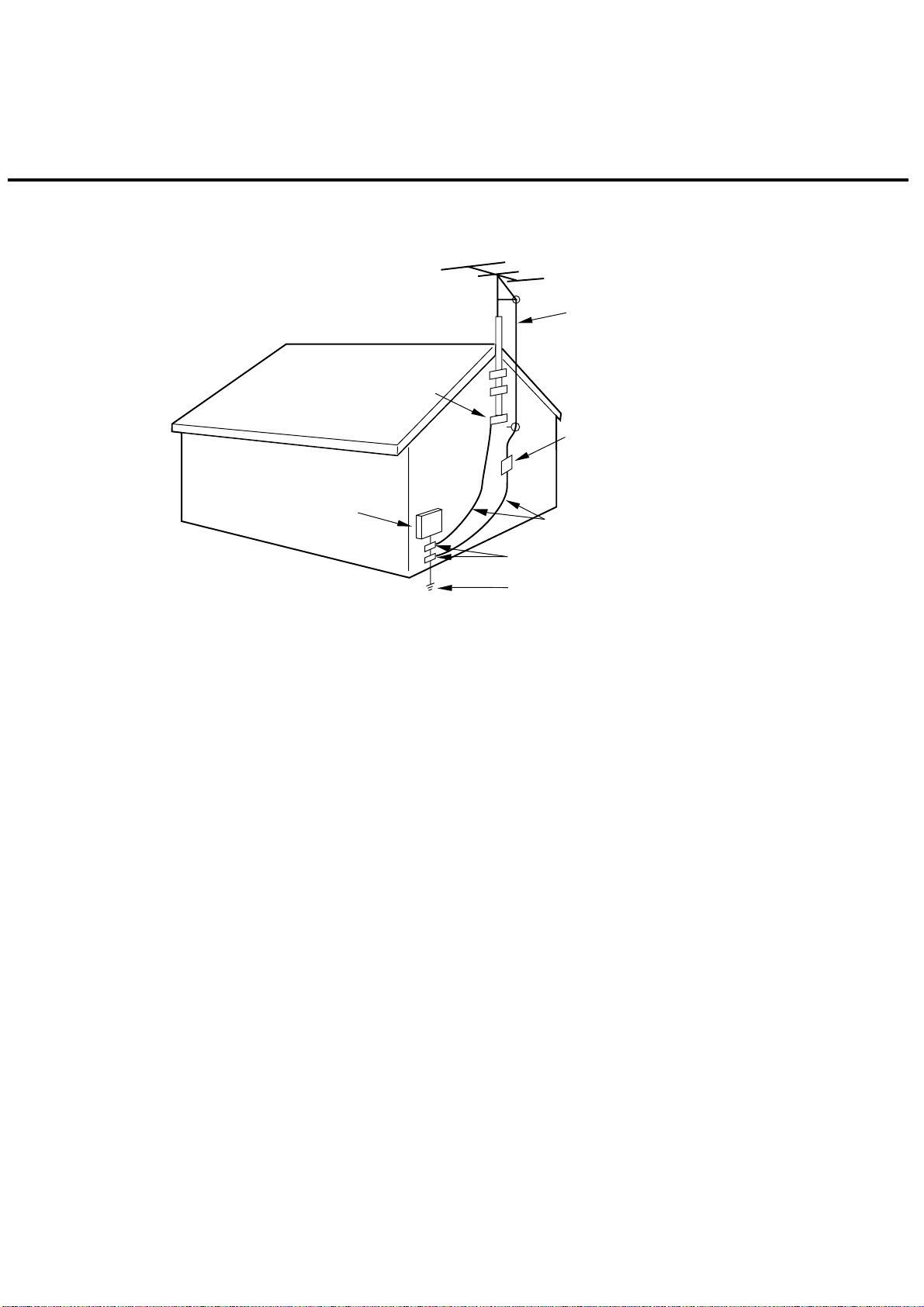
OUTDOOR ANTENNA GROUNDING
If an outside antenna or cable system is connected to the unit, be sure the antenna or cable system is grounded
so as to provide some protection against voltage surges and built-up static charges. Section 810 of the National
Electrical Code, ANSI/NFPA 70, provides information with respect to proper grounding of the mast and supporting
structure, grounding of the lead-in wire to an antenna discharge unit, size of grounding conductors, location of
antenna discharge unit, connection to grounding electrodes, and requirements for the grounding electrode.
SERVICING
Do not attempt to service this unit yourself as opening or removing covers may expose you to dangerous voltage
or other hazards. Refer all servicing to qualified service personnel.
DAMAGE REQUIRING SERVICE
Unplug this unit from the wall outlet and refer servicing to qualified service personnel under the following
conditions:
REPLACEMENT PARTS
When replacement parts are required, be sure the service technician uses replacement parts specified by the
manufacturer or those that have the same characteristics as the original parts.
Unauthorized substitutions may result in fire, electric shock or other hazards.
SAFETY CHECK
Upon completion of any service or repairs to this unit, ask the service technician to perform safety checks to
determine that the unit is in proper operating condition.
WALL OR CEILING MOUNTING
The product should be mounted to a wall or ceiling only as recommended by the manufacturer.
HEAT
The product should be situated away from heat sources such as radiators, heat registers, stoves, or other
products (including amplifiers) that produce heat.
DISC TRAY
Keep your fingers well clear of the disc tray as it is closing. It may cause serious personal injury.
CONNECTING
When you connect the product to other equipment, turn off the power and unplug all of the equipment from the
wall outlet. Failure to do so may cause an electric shock and serious personal injury. Read the owner's manual of
the other equipment carefully and follow the instructions when making any connections.
SOUND VOLUME
Reduce the volume to the minimum level before you turn on the product. Otherwise, sudden high volume sound
may cause hearing or speaker damage.
SOUND DISTORTION
Do not allow the product output distorted sound for a longtime. It may cause speaker overheating and fire.
HEADPHONES
When you use the headphones, keep the volume at a moderate level. If you use the headphones continuously
with high volume sound, it may cause hearing damage.
LASER BEAM
Do not look into the opening of the disc tray or ventilation opening of the product to see the source of the laser
beam. It may cause sight damage.
DISC
Do not use a cracked, deformed, or repaired disc. These discs are easily broken and may cause serious
personal injury and product malfunction.
NOTE TO CATV SYSTEM INSTALLER
This reminder is provided to call the CATV system installer’s attention to Article 820-40 of the NEC that provides
guidelines for proper grounding and, in particular, specifies that the cable ground shall be connected to the
grounding system of the building, as close to the point of cable entry as practical.
17.
18.
19.
20.
21.
22.
23.
24.
25.
26.
27.
28.
29.
30.
31.
a.
b.
c.
d.
e.
f.
When the power-supply cord or plug is damaged.
If liquid has been spilled, or objects have fallen into the unit.
If the unit has been exposed to rain or water.
If the unit does not operate normally by following the operating instructions. Adjust only those controls that
are covered by the operating instructions, as an improper adjustment of other controls may result in
damage and will often require extensive work by a qualified technician to restore the unit to its normal
operation.
If the unit has been dropped or the cabinet has been damaged.
When the unit exhibits a distinct change in performance, this indicates a need for service.
A1-6
EXAMPLE OF ANTENNA GROUNDING AS PER THE NATIONAL ELECTRICAL CODE
ANTENNA
DISCHARGE UNIT
(NEC SECTION 810-20)
ANTENNA LEAD
IN WIRE
GROUNDING CONDUCTORS
(NEC SECTION 810-21)
GROUND CLAMPS
POWER SERVICE GROUNDING
ELECTRODE SYSTEM
(NEC ART 250, PART H)
GROUND
CLAMP
ELECTRIC SERVICE
EQUIPMENT
NEC-NATIONAL ELECTRICAL CODE
S2898A
IMPORTANT SAFEGUARDS (CONTINUED)

A1-7
Before removing Pick Up PCB and DVD PCB connector, the short circuit the position shown in Fig. 1
using a soldering iron. If you remove the DVD Deck with no soldering, the Laser may be damaged.
WHEN REPLACING DVD DECK
[ When removing the DVD Deck ]
[ When installing the DVD Deck ]
Remove all the soldering on the short circuit position after the connection of Pick Up PCB and DVD
PCB connector.
NOTE
Fig. 1
Before your operation, please read “PREPARATION OF SERVICING”.
Use the Lead Free solder.
Manual soldering conditions
• Soldering temperature: 350 ± 5˚C
• Soldering time: Within 2 seconds
• Soldering combination: Sn-3.0Ag-0.5Cu
When Soldering/Removing of solder, use the draw in equipment over the Pick Up Unit to keep the
Flux smoke away from it.
•
•
•
•
Short circuit using a
soldering iron.
Pick Up PCB
A1-8
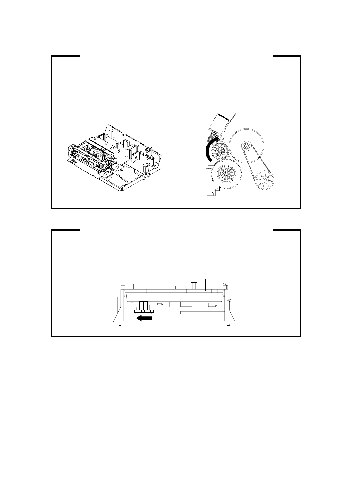
1.
2.
3.
Remove the Back Cabinet and AV PCB/DVD Block. (Refer to item 1 of the DISASSEMBLY
INSTRUCTIONS.)
Rotate the Main Gear in the direction of the arrow by hand.
(Refer to Fig. 1)
Manually open the Tray.
DISC REMOVAL METHOD AT NO POWER SUPPLY
Fig. 1
Deck CDMain Gear
1.
2.
3.
4.
5.
Remove the TV/DVD/VCR block from the main unit as shown in Fig. 1 below can be seen.
(Refer to item 1 of the DISASSEMBLY INSTRUCTIONS.)
Remove the screw 1 of the Deck Chassis and remove the Loading Motor.
Rotate the Pinch Roller Cam in the direction of the arrow by hand to slacken the Video Tape.
(Refer to Fig. 2)
Rotate the Clutch Ass'y either direction to wind the Video Tape in the Cassette Case.
Repeat steps 3~4. Then take out the Video Cassette from the Deck Chassis. Be careful not to scratch
the tape.
TAPE REMOVAL METHOD AT NO POWER SUPPLY
Fig. 1
Pinch Roller Cam
Main Cam
Clutch Ass'y
Main Chassis (Front Side)
Loading Motor
Screw 1
Capstan DD Unit
Fig. 2

A1-9
Tray cannot be opened by setting the Tray Lock, please follow the steps below.
Turn Unit ON.
Set the DVD to the Stop Mode.
Press it in order of 'SETUP', 'SUBTITLE', '3', 'AUDIO SELECT' and '0' key of a remote control unit.
The On Screen Display message ' ' will appear.
The Tray Lock has now been set up.
1.
2.
3.
4.
5.
TRAY LOCK
To unlock the Tray Lock, please follow the steps below.
Turn Unit ON.
Set the DVD to the Stop Mode.
Press it in order of 'SETUP', 'SUBTITLE', '3', 'AUDIO SELECT' and '0' key of a remote control unit.
The On Screen Display message ' ' will appear.
The Tray Lock has now been cleared.
1.
2.
3.
4.
5.
PARENTAL CONTROL - RATING LEVEL
4 DIGIT PASSWORD CANCELLATION
If the stored 4 digit password in the Rating Level menu needs to be cancelled, please follow the steps below.
Turn Unit ON.
Set the DVD Mode.
Confirm that the 'No Disc' will be appeared on the screen.
Press and hold the '7' key on the remote control unit.
Simultaneously press and hold the 'STOP' key on the front panel.
Hold both keys for more than 3 seconds.
The On Screen Display message 'PASSWORD CLEAR' will appear.
The 4 digit password has now been cleared
1.
2.
3.
4.
5.
6.
7.
8.

TABLE OF CONTENTS
A1-1
A1-1
A1-2
A1-3
A1-3
A1-4~A1-6
A1-7
A1-8
A1-8
A1-9
A1-9
A2-1
A3-1~A3-6
B1-1~B1-3
B2-1~B2-6
B3-1~B3-4
B4-1
B5-1, B5-2
C1-1, C1-2
C2-1
C3-1, C3-2
C4-1
D1-1
D1-1
D2-1~D2-4
D3-1~D3-6
E-1, E-2
E-3, E-4
E-5, E-6
E-7, E-8
E-9, E-10
E-11, E-12
E-13, E-14
E-15, E-16
E-17, E-18
E-19, E-20
E-21, E-22
F-1, F-2
F-3~F-6
F-7~ F-10
F-11, F-12
G-1, G-2
G-3, G-4
G-5, G-6
G-7, G-8
G-9, G-10
G-11, G-12
G-13, G-14
G-15, G-16
G-17, G-18
G-19, G-20
G-21, G-22
G-23, G-24
G-25, G-26
G-27, G-28
G-29, G-30
G-31, G-32
G-33, G-34
G-35, G-36
G-37, G-38
G-39, G-40
G-41, G-42
G-43, G-44
G-45, G-46
G-47, G-48
G-49, G-50
G-51, G-52
H-1~H-3
I1-1~I1-3
I2-1, I2-2
I3-1
J1-1, J1-2
J2-1
J3-1
J4-1~J4-8
A2-1
GREEN PRODUCT PROCUREMENT .....................................................................................
LEAD-FREE SOLDER .............................................................................................................
CAUTION .................................................................................................................................
SERVICING NOTICES ON CHECKING..................................................................................
HOW TO ORDER PARTS .......................................................................................................
IMPORTANT SAFEGUARDS..................................................................................................
WHEN PERLACING DVD DECK ............................................................................................
TAPE REMOVAL METHOD AT NO POWER SUPPLY .........................................................
DISC REMOVAL METHOD AT NO POWER SUPPLY ..........................................................
PARENTAL CONTROL RATING LEVEL ...............................................................................
TRAY LOCK.............................................................................................................................
TABLE OF CONTENTS...........................................................................................................
GENERAL SPECIFICATIONS ................................................................................................
DISASSEMBLY INSTRUCTIONS
1. REMOVAL OF MECHANICAL PARTS AND P. C. BOARDS.........................................
2. REMOVAL OF VCR DECK PARTS ................................................................................
3. REMOVAL OF DVD DECK PARTS ................................................................................
4. REMOVAL OF ANODE CAP...........................................................................................
5. REMOVAL AND INSTALLATION OF FLAT PACKAGE IC ............................................
KEY TO ABBREVIATIONS .....................................................................................................
SERVICE MODE LIST .............................................................................................................
PREVENTIVE CHECKS AND SERVICE INTERVALS...........................................................
WHEN REPLACING EEPROM (MEMORY) IC ......................................................................
SERVICING FIXTURES AND TOOLS ....................................................................................
PREPARATION FOR SERVICING..........................................................................................
MECHANICAL ADJUSTMENTS .............................................................................................
ELECTRICAL ADJUSTMENTS...............................................................................................
BLOCK DIAGRAMS
DVD.......................................................................................................................................
SD DIGITAL MODULE .........................................................................................................
Y/C/AUDIO/HEAD AMP .......................................................................................................
MICON ..................................................................................................................................
IN/OUT ..................................................................................................................................
CHROMA/IF..........................................................................................................................
SOUND AMP/SURROUND/REGULATOR ..........................................................................
Hi-Fi/DEMODULATOR .........................................................................................................
TUNER/DIGITAL COMB FILTER/DVD IN/OUT...................................................................
REGULATOR........................................................................................................................
TV .........................................................................................................................................
PRINTED CIRCUIT BOARDS
DVD/USB ..............................................................................................................................
VCR.......................................................................................................................................
DEFLECTION/CRT/REGULATOR/OPERATION/VM COIL ................................................
DIGITAL/LOADING MOTOR/SW .........................................................................................
SCHEMATIC DIAGRAMS
MPEG/MICON/DSP/RF_AMP ..............................................................................................
MEMORY ..............................................................................................................................
MOTOR DRIVE ....................................................................................................................
AUDIO/VIDEO ......................................................................................................................
USB.......................................................................................................................................
Y/C/AUDIO/HEAD AMP .......................................................................................................
MICON ..................................................................................................................................
IN/OUT ..................................................................................................................................
CHROMA/IF..........................................................................................................................
Hi-Fi ......................................................................................................................................
TUNER/DVD IN/OUT ...........................................................................................................
REGULATOR........................................................................................................................
TV POWER...........................................................................................................................
COMB FILTER......................................................................................................................
ASIC......................................................................................................................................
SDRAM .................................................................................................................................
FLASH ..................................................................................................................................
FRONT END .........................................................................................................................
AV OUT.................................................................................................................................
DEFLECTION .......................................................................................................................
SOUND AMP/SURROUND ..................................................................................................
CRT / SVM............................................................................................................................
OPERATION.........................................................................................................................
DTV REGURATOR...............................................................................................................
LOADING MOTOR/SW ........................................................................................................
INTERCONNECTION DIAGRAM ............................................................................................
WAVEFORMS ..........................................................................................................................
MECHANICAL EXPLODED VIEWS........................................................................................
CHASSIS EXPLODED VIEWS ................................................................................................
DVD DECK EXPLODED VIEWS .............................................................................................
MECHANICAL REPLACEMENT PARTS LIST ......................................................................
CHASSIS REPLACEMENT PARTS LIST...............................................................................
DVD DECK REPLACEMENT PARTS LIST............................................................................
ELECTRICAL REPLACEMENT PARTS LIST........................................................................
GENERAL SPECIFICATIONS
G-1 TV CRT CRT Size / Visual Size 27 inch / 676.6mmV
System CRT Type Flat
Magnetic Field BV/BH +0.45G / 0.18G
Color System NTSC
Speaker 2 Speaker
Position Front
Size 1.8 x 3.9 Inch
Impedance 8 ohm
Sound Output MAX 2.5W + 2.5W
10%(Typical) __
G-2 VCR System VHS Player / Recorder
System Video System NTSC
Hi-Fi STEREO Yes
NTSC PB -
Deck OVD-7
Heads Video Head 4 Heads
FM Audio Head 2 Heads
Audio /Control Mono /Yes
Erase(Full Track Erase) Yes
Erase (Normal Audio Track Erase) Yes
Tape Rec PAL -
Speed NTSC SP/SLP(EP)
Play PAL -
NTSC SP/SLP(EP)
Fast Forward / Rewind Time (Approx.) at 25oC FF:1'48"/REW:1'48"
with Cassette T-120
Forward/Reverse NTSC or PAL-M SP/SLP(EP)=3x,5x / 9x,15x
Picture Search
Frame Advance Yes
Slow Speed 1/10
G-3 DVD System Color System NTSC
Disc DVD, CD-DA, CD-R/RW, Video CD
DVD-R/RW (Video Format Only)
Disc Diameter 120 mm , 80 mm
Drive DM3SA
Search speed Fwd 4 step
Actual 2-120 times(DVD, VIDEO CD)
4-40 times (CD)
Rev 4 step
Actual 2-120 times(DVD, VIDEO CD)
4-40 times (CD)
Slow speed Fwd 1/7 - 1/2 times
Actual --
Rev --
Actual --
G-4 Tuning Broadcasting System Analog US System M
System Digital ATSC(8VSB), QAM
Tuner and System 1 Tuner
Receive CH Destination US(w/CABLE)
CH Coverage 2~69, 4A, A-5~A-1, A~I, J~W, W+1~W+84
Intermediate Digital 44.00MHz
Frequency Analog Picture(FP) 45.75MHz
Sound(FS) 41.25MHz
FP-FS 4.5MHz
Preset CH
No
Stereo/Dual TV Sound US-Stereo
Tuner Sound Muting Yes
A3-1

GENERAL SPECIFICATIONS
G-5 Signal Video Signal Input Level 1 V p-p/75 ohm
Output Level -
S/N Ratio (Weighted) at DVD Mode -
S/N Ratio (Weighted) at VCR Mode -
Horizontal Resolution at DVD Mode -
Horizontal Resolution at VCR(SP)Mode -
RGB Signal Output Level -
Audio Signal Input Level -8.0dBm/50k ohm
VCR Output Level(0dB=0.775Vrms) -
DVD Output Level(-20dBFs 0dBFs=2.0Vrms) -
Digital Output Level 0.5 V p-p/75 ohm(DVD/DTV)
S/N Ratio at DVD (Weighted) -
S/N Ratio at VCR (SP)(CCIR Filter:ON) -
Harmonic Distortion at DVD Mode -
Harmonic Distortion at VCR(SP) Mode -
Frequency Response :
DVD Mode at DVD -
at Video CD -
at SVCD -
at CD -
VCR Mode at SP -
at LP -
at SLP -
Hi-Fi Audio Signal Dynamic Range : More than 90 dB
Frequency Response : 20Hz - 20kHz
Wow And Flutter : Less than 0.01 %Wrms
Channel Separation : More than 60 dB
Harmonic Distortion : Less than 1.0 %
G-6 Power Power Source AC 120V,60Hz
DC -
Power Consumption at AC 150 W at 120 V 60 Hz
at DC -
Stand by (at AC) 4 W at 120 V 60 Hz
Per Year -
Energy Star
No
Protector Power Fuse Yes
Safety Circuit Yes
IC Protector(Micro Fuse) No
Dew Sensor
No
G-7 Regulation Safety UL
Radiation FCC
X-Radiation DHHS
Laser DHHS
G-8 Temperature Operation +5oC ~ +40oC
Storage -20oC ~ +60oC
G-9 Operating Humidity Less than 80% RH
G-10 OSD Language English French Spanish
G-11 Clock,Timer Calendar 1990/1/1 ~ 2081/12/31
and Timer Timer Events 8 Program/ 1 Month
Back-up One Touch Recording Max Time 6 Hours
Sleep Timer Max Time 120
Min
Step 10
Min
On/Off Timer Program(On Timer / Off Timer) 1
Program
Auto Shut Off No Signal 15
Min
No Operation -
Min
Timer Back-up (at Power Off Mode) 5
Sec
A3-2

GENERAL SPECIFICATIONS
G-12 Remote Unit RC-KH
Control Glow in Dark Remocon No
Unit Remocon Format TOSHIBA
Format TOSHIBA
Custom Code 40-BFh, 44-BBh, 45-BAh
Power Source Voltage(D.C) 3V
UM size x pcs UM-4 x 2 pcs
Total Keys 50
Keys
TV/VCR
Yes
DVD
Yes
Power
Yes
1
Yes
2
Yes
3
Yes
4
Yes
5
Yes
6
Yes
7
Yes
8
Yes
9
Yes
0
Yes
Channel-
Yes
Channel+
Yes
Volume-
Yes
Volume+
Yes
Display/-
Yes
Sleep
Yes
Audio Select
Yes
Mute
Yes
Channel Return / Skip-
Yes
Closed Caption / Skip+
Yes
TIMER REC
Yes
REC/OTR
Yes
Slow+
Yes
Play
Yes
Stop
Yes
REV(Rew)
Yes
FF(F. Fwd)
Yes
Pause / Still /Step
Yes
CM Skip / Jump
Yes
Speed / Return
Yes
Counter Reset / Angle
Yes
Zero Return / Subtitle
Yes
Input Select / Zoom
Yes
Menu /Setup
Yes
Program / Repeat A-B / DVD/USB
Yes
D.Tracking / Top Menu
Yes
Tracking+ / DVD Menu
Yes
Tracking- / Play Mode
Yes
Cancel
Yes
Cursor Up
Yes
Cursor Down
Yes
Cursor Left
Yes
Cursor Right
Yes
Enter
Yes
Open/Close
Yes
Eject Yes
Picture Size
Yes
A3-3
GENERAL SPECIFICATIONS
G-13 Features Auto Head Cleaning Yes
(TV/VCR) VIDEO PLUS+(SHOWVIEW,G-CODE)
No
Forward / Reverse Picture Search Yes
Index Search
No
SQPB
No
CM Skip(30sec x 6 Times) Yes
Zero Return Yes
End Call
No
TV Monitor
No
Program Extend
No
Picture Brightness , Contrast , Color, Sharpness Yes
Tint Yes
Mode (Picture Preference) Yes
Color Temperature Yes
CableClear
No
Cinema Mode
No
Aspect
No
Audio Tone Control (Bass/Treble/Balance) Yes
Stable Sound Yes
Surround Yes
Timer On Timer Yes
Off Timer Yes
Sleep Timer Yes
Game Timer
No
Tuning Auto CH Memory Yes
ADD/Delete Yes
Label CH Label
No
Video Label
No
Favorite CH
No
Lock Hotel Lock
No
Channel Lock
No
Video Lock
No
Front Panel Lock
No
Closed Caption (Analog & Digital) Yes
CC Advance Yes
Signal Mater Yes
Auto Setup Yes
Auto Clock Yes
Picture Size Yes
Picture Scroll
No
Zoom Yes
CABLE Yes
QAM Yes
SAP Yes
Comb Filter Yes
3 Lines
VM Circuit Yes
Protect of FBT Leak Circuit Yes
TV Auto Shut off Function Yes
Power On Memory
No
Choke Coil
No
V-chip USA V-chip Yes
CANADA V-chip
No
RRT Setup
No
Digital Out Dolby Digital Yes
MPEG
No
PCM Yes
DTS
No
HDMI Input
No
Component Input Yes
720x480i (4:3) Yes (60Hz)
720x480i (16:9) Yes (60Hz)
720x480p (4:3) No
720x480p (16:9) No
720x576i (4:3) No
720x576i (16:9) No
720x576p (4:3) No
720x576p (16:9) No
1280x720p No
1920x1080i No
A3-4
GENERAL SPECIFICATIONS
Features Tray Lock Yes
(DVD) Auto Stop (Pause, and Resume Stop after 5min.) Yes
USB (Some USB devices may not be usable.) Yes
Card Slot Reading (Not secured Data) No
Video CD Playback Yes
SVCD Playback
No
MP3 Playback Yes
WMA Playback Yes
JPEG Playback Yes
DivX Play back Yes
DMF Support
No
Digital Out (Dolby Digital) Yes
(MPEG) Yes
(PCM) Yes
(DTS) Yes
Down Mix Out (Dolby Digital) Yes
(DTS)
No
Surround
No
Closed Caption Signal in VBI (DVD Playback)
Yes
Screen Saver
No
Audio DAC 192kHz / 24bit
Copy (Disc to Tape) Yes (by Conditioning)
G-14 Accessories Owner's Manual Language English
w/Guarantee Card Yes
Remote Control Unit Yes
Battery Yes
UM size x pcs UM-4 x 2 pcs
OEM Brand
No
Rod Antenna
No
Poles -
Terminal -
Loop Antenna
No
Terminal -
U/V Mixer
No
300 ohm to 75 ohm Antenna Adapter Yes
Antenna Change Plug
No
DC Car Cord (Center+)
No
AC Plug Adapter
No
AC Cord
No
AV Cord (2Pin-1Pin)
No
Guarantee Card
No
Registration Card Yes
ESP Card
No
Warning Sheet Yes
Dew/AHC Caution Sheet
No
Quick Set-up Sheet Yes
Circuit Diagram
No
Service Facility List
No
Important Safeguard
No
Information Sheet (Return) Yes
Netflix Card No
A3-5
GENERAL SPECIFICATIONS
G-15 Interface Switch Front Power (Tact) Yes
Channel Up Yes
Channel Down Yes
Volume Up Yes
Volume Down Yes
Play (VCR) Yes
Stop / Eject (VCR) Yes
F.FWD/Cue (VCR) Yes
Rew/Rev (VCR) Yes
REC/OTR (VCR) Yes
Play (DVD) Yes
Stop (DVD) Yes
Skip+ /Search+ (DVD) Yes
Skip- /Search- (DVD) Yes
Open/Close (DVD) Yes
Input Select No
Main Power SW No
Indicator Power Yes (Red)
REC/OTR Yes (Red)
T-REC Yes (Red)
TV/VCR No
DVD No
Terminals Front Video Input RCA x 1 (Yellow)
Audio Input RCA x 2 (L/MONO,R White,Red)
S-Video Input
Yes
USB
Yes
Other Terminal No
Rear Video Input RCA x 1 (Yellow)
Audio Input RCA x 2 (L/MONO,R White,Red)
Video Output No
Audio Output No
Component Input
RCA x 3
Audio Input
RCA x 2 (L/MONO, R White,Red)
Digital Audio Output Coaxial (DTV & DVD Only)
VHF/UHF Antenna Input F Type
AC Inlet No
G-16 Set Size Approx. W x D x H (mm) 740 x 493 x 645
G-17 Weight Net (Approx.) 44.0kg (97.0lbs)
Gross (Approx.) 48.5kg (107.0lbs)
G-18 Carton Master Carton
No
Content -
Material -
Dimensions W x D x H(mm) -
Description of Origin -
Gift Box Material Double/Brown
Dimensions W x D x H(mm) 851 x 618 x 776
Description of Origin Yes
Drop Test Natural Dropping At 1 Corner / 2 Edges / 4 Surfaces
Height (cm) 40(ORION SPEC:25)
Container Stuffing(40' container) 156
Sets
G-19 Material Cabinet Front PS 94V0 DECABROM
Rear PS 94V0 DECABROM
Jack Panel -
PCB Non-Halogen Demand No
Eyelet Demand Yes
G-20 Environment Environmental standard requirement (by buyer) Green procurement of TOSHIBA
Pb-free Phase3(Phase3A)
Measures for Whisker Yes
A3-6
DISASSEMBLY INSTRUCTIONS
B1-1
1. REMOVAL OF MECHANICAL PARTS
AND P.C. BOARDS
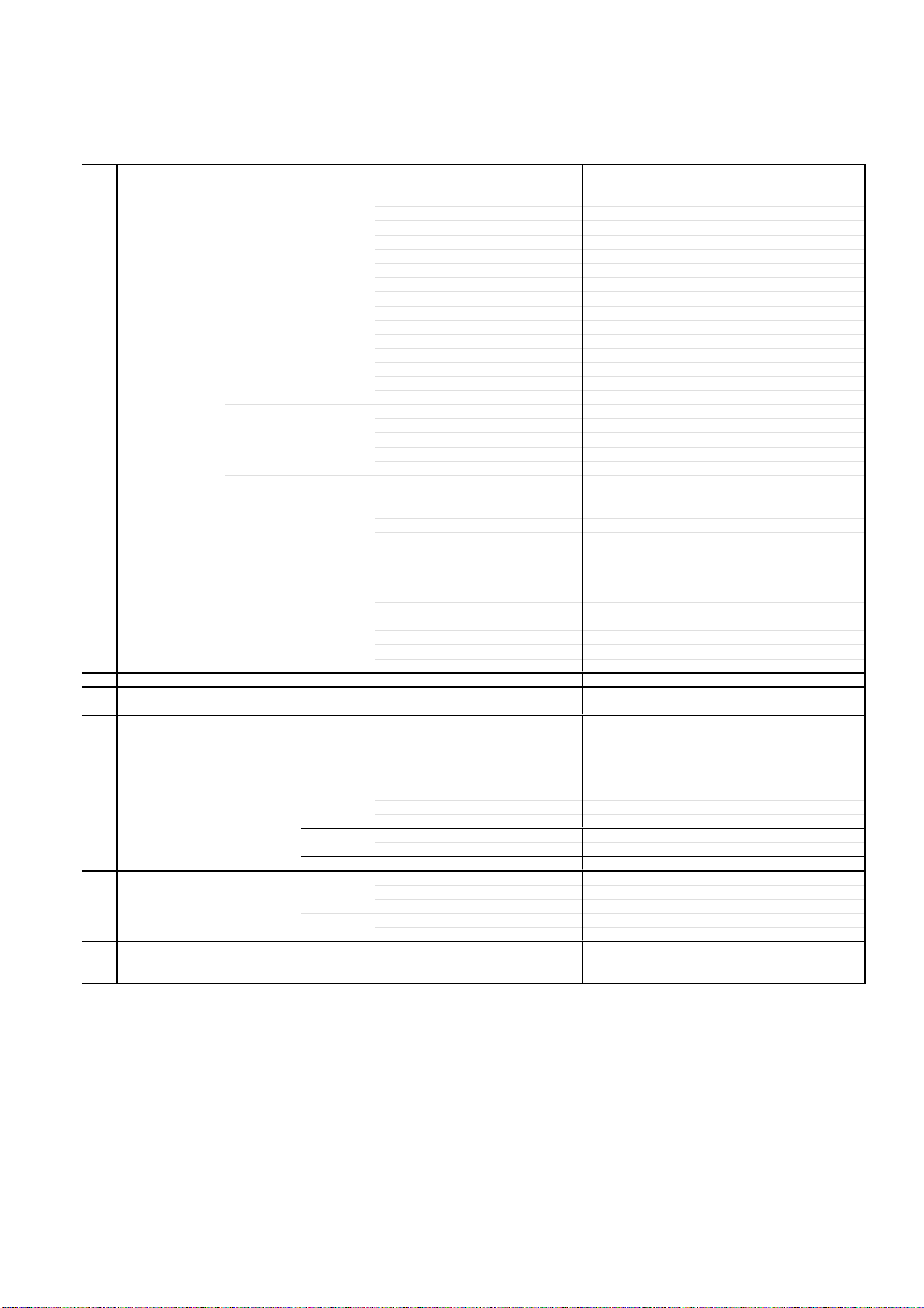
1-1: BACK CABINET (Refer to Fig. 1-1)
1.
2.
3.
Remove the 6 screws 1.
Remove the 2 screws 2.
Remove the Back Cabinet in the direction of arrow.
1-2: CRT PCB (Refer to Fig. 1-2)
CAUTION: BEFORE REMOVING THE ANODE CAP,
DISCHARGE ELECTRICITY BECAUSE IT
CONTAINS HIGH VOLTAGE.
BEFORE ATTEMPTING TO REMOVE OR
REPAIR ANY PCB, UNPLUG THE POWER
CORD FROM THE AC SOURCE.
1.
2.
3.
Remove the Anode Cap.
(Refer to REMOVAL OF ANODE CAP)
Disconnect the following connectors:
(CP801B, CP802B, CP803, CP806, CP851B and CP852A).
Remove the CRT PCB in the direction of arrow.
CRT PCB
Front Cabinet
Fig. 1-1
Fig. 1-2
Front Cabinet
1
1
1
1
Back Cabinet
1
1
2
2
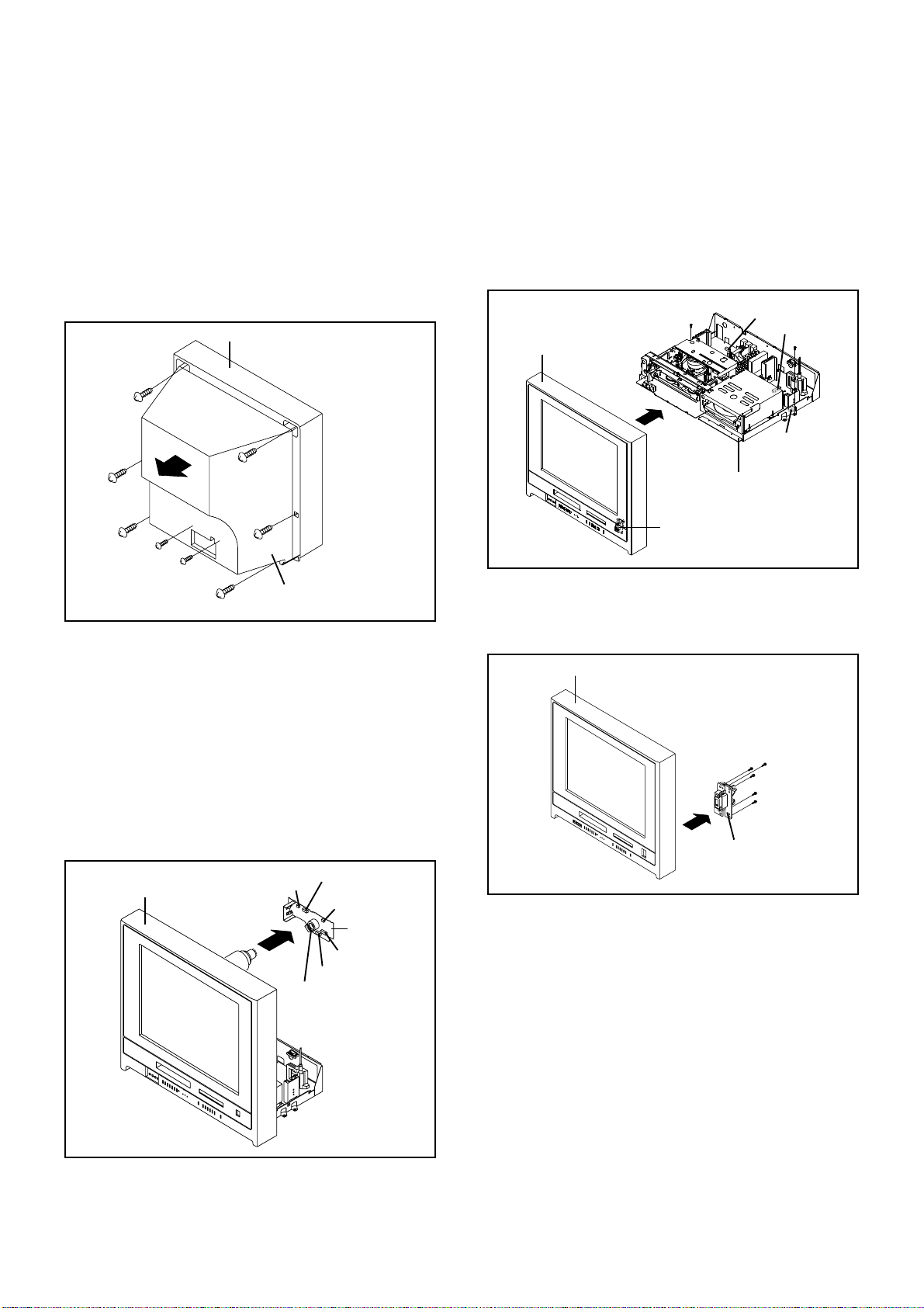
1-3: TV/DVD/VCR BLOCK (Refer to Fig. 1-3)
1.
2.
3.
Remove the 2 screws 1.
Disconnect the following connectors:
(CP351, CP404, CP1704 and CP5902).
Remove the TV/DVD/VCR Block in the direction of arrow.
Fig. 1-3
CP801B
CP803
CP802B
CP404
CP1704
TV/DVD/VCR Block
1
1
Front Cabinet
CP351
CP851B
CP852A
CP806
CP5902
1-4: TV/DVD/VCR BLOCK (Refer to Fig. 1-4)
1.
2.
Remove the 5 screws 1.
Remove the USB PCB in the direction of arrow.
Fig. 1-4
1
Front Cabinet
1
1
1
USB PCB
1
DISASSEMBLY INSTRUCTIONS
B1-2
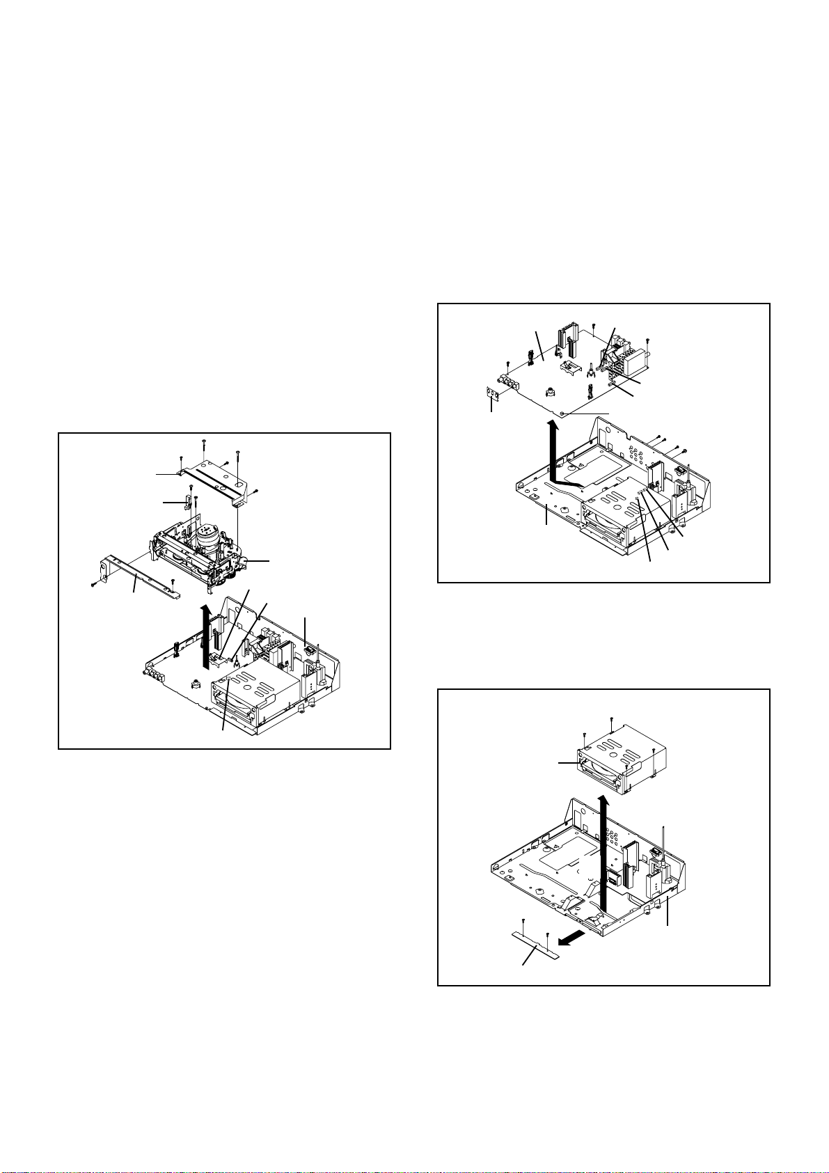
1-6: VCR PCB (Refer to Fig. 1-6)
1.
2.
3.
4.
5.
Remove the 6 screws 1.
Remove the screw 2.
Remove the AV Jack Shield.
Disconnect the following connectors:
(CP001, CP301, CP602B, CP604, CP2201, CP8001 and
CP8002).
Remove the VCR PCB in the direction of arrow.
Fig. 1-6
1
1
1
1
1
1
2
VCR PCB
Bottom Plate
AV Jack Shield
CP2201
CP8001
CP8002
CP602B
CP604
CP001
1-5: VCR DECK (Refer to Fig. 1-5)
NOTE
Do not remove the cable at the FE Head section. The FE
Head may be damaged if you remove the cable by force.
1.
2.
3.
4.
5.
6.
7.
8.
9.
10.
11.
Remove the 2 screws 1.
Remove the VCR Top.
Move the Cassette Holder Ass'y to the back side.
Remove the 3 screws 2.
Remove the screw 3.
Remove the 2 screws 4.
Remove the Deck Shield Cover.
Remove the screw 5.
Remove the FE Head.
Disconnect the following connectors:
(CP101, CP4501 and CP4502).
Remove the VCR Deck in the direction of arrow.
Fig. 1-5
1
1
VCR Top
2
2
2
3
4
Deck Shield Cover
5
FE Head
VCR Deck
Bottom Plate
CP101
CP4501
CP4502
4
CP301
1-7: DVD BLOCK/OPERATION PCB (Refer to Fig. 1-7)
1.
2.
3.
4.
Remove the 4 screws 1.
Remove the DVD Block in the direction of arrow (A).
Remove the 2 screws 2.
Remove the Operation PCB in the direction of arrow (B).
Fig. 1-7
DVD Block
1
1
1
1
(A)
2
2
(B)
Operation PCB
Bottom Plate
DISASSEMBLY INSTRUCTIONS
B1-3
Deflection PCB
1
1
Bottom Plate
2
2
2
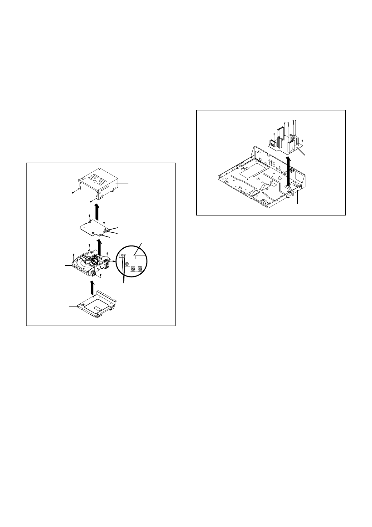
1-8: DVD PCB/DVD DECK (Refer to Fig. 1-8)
1.
2.
3.
4.
5.
6.
7.
8.
Short circuit the position shown in Fig. 1-8 using a
soldering iron. If you remove the DVD Deck with no
soldering, the Laser may be damaged.
Remove the 2 screws 1.
Remove the DVD Top in the direction of arrow (A).
Remove the 4 screws 2.
Remove the DVD Deck in the direction of arrow (B).
Disconnect the following connectors:
(CP2301, CP2302 and CP2303).
Remove the 2 screws 3.
Remove the DVD PCB in the direction of arrow (C).
1-9: DEFLECTION PCB (Refer to Fig. 1-9)
1.
2.
3.
Remove the 2 screws 1.
Remove the 3 screws 2.
Remove the Deflection PCB in the direction of arrow.
Fig. 1-9
Fig. 1-8
1
(A)
Angle Deck
2
(B)
(C)
3
DVD PCB
Pick Up PCB
1
DVD Top
2
2
2
Short circuit using a
soldering iron.
3
DVD Deck
NOTE
Before your operation, please read “PREPARATION OF
SERVICING”.
Use the Lead Free solder.
Manual soldering conditions
• Soldering temperature: 350 ± 5˚C
• Soldering time: Within 2 seconds
• Soldering combination: Sn-3.0Ag-0.5Cu
When Soldering/Removing of solder, use the drawing
equipment over the Pick Up Unit to keep the Flux smoke
away from it.
When installing the DVD Deck, remove all the soldering on
the short circuit position after the connection of Pick Up
PCB and DVD PCB connector.
1.
2.
3.
4.
5.
CP2301
CP2302
CP2303
DISASSEMBLY INSTRUCTIONS
B2-1
2. REMOVAL OF VCR DECK PARTS
2-1: TOP BRACKET (Refer to Fig. 2-1)
Extend the 2 supports 1.
Slide the 2 supports 2 and remove the Top Bracket.
1.
2.
2-2: CASSETTE HOLDER ASS'Y (Refer to Fig. 2-2)
Move the Cassette Holder Ass'y to the front side.
Push the Locker R to remove the Cassette Side R.
Remove the Cassette Side L.
1.
2.
3.
Fig. 2-1
2
2
Main Chassis
Main Chassis
Top Bracket
Top Bracket
Main Chassis
Main Chassis
Cassette Side L
Cassette Side R
Locker R
Fig. 2-2
Link Unit
2-3: LINK UNIT (Refer to Fig. 2-3)
Set the Link Unit to the Eject position.
Unlock the support 1.
Remove the (A) side of the Link Unit first, then remove
the (B) side.
1.
2.
3.
Fig. 2-3
(A)
Link Unit
Main Chassis
1
Link Unit
(B)
Main Chassis
1
1
NOTE
1. After installation of the Top Bracket, bend the support 1
so that the Top Bracket is fixed.
2-4: LINK LEVER/FLAP LEVER (Refer to Fig. 2-4)
Extend the support 1.
Remove the Link Lever.
Remove the Flap Lever.
1.
2.
3.
Fig. 2-4
Link Lever
Flap Lever
1

DISASSEMBLY INSTRUCTIONS
B2-2
2-5: LOADING MOTOR/WORM (Refer to Fig. 2-5-A)
1.
2.
3.
Remove the screw 1.
Remove the Loading Motor.
Remove the Worm.
Fig. 2-5-A
Loading Motor
Worm
• Screw Torque: 3 ± 0.5kgf•cm
Main Chassis
1
2-6: TENSION ASS’Y (Refer to Fig. 2-6-B)
1.
2.
3.
4.
5.
6.
Turn the Pinch Roller Cam clockwise so that the Tension
Holder hook is set to the position of Fig. 2-6-A to move
the Tension Arm Ass’y.
Remove the Tension Spring.
Unlock the 2 supports 1 and remove the Tension Band.
Unlock the support 2 and remove the Tension Arm Ass’y.
Unlock the support 3 and remove the Tension Connect.
Float the hook 4 and turn it clockwise then remove the
Tension Holder.
Fig. 2-6-B
Tension Band
Tension Connect
Tension Spring
Tension Arm Ass’y
Tension Holder
1
1
3
2
4
NOTE
1.
2.
3.
In case of the Tension Band installation, note the direc-
tion of the installation. (Refer to Fig. 2-6-C)
In case of the Tension Band installation, install correctly
as Fig. 2-6-D.
In case of the Tension Connect installation, install as the
circled section of Fig. 2-6-E.
Fig. 2-6-C
Tension Band
Tension Connect
Tension Arm Ass’y
Fig. 2-6-A
NOTE
1.
2.
3.
In case of the Worm installation, check if the value of the
Fig. 2-5-B is correct.
In case of the Loading Motor installation, slacken the wire
as shown Fig. 2-5-C.
When installing the wires between Capstan DD Unit and
Loading Motor, connect them correctly as shown Fig. 2-5-
D.
Loading Motor Capstan DD Unit
-
+
L2
L1
Pink
Fig. 2-5-D
White
Fig. 2-5-B
19.2 ± 0.1mm
Safety surface for pressing
of the insert.
Fig. 2-5-C
Loading Motor
Slacken the wire.

DISASSEMBLY INSTRUCTIONS
B2-3
Fig. 2-6-D
[OK]
[NG]
Tension Connect
Tension Band
Tension Connect
Tension Band
Fig. 2-6-E
Tension Connect
Main Chassis
2-7: T BRAKE ARM/T BRAKE BAND (Refer to Fig. 2-7-A)
Remove the T Brake Spring.
Turn the T Brake Arm clockwise and bend the hook
section to remove it.
Unlock the 2 supports 1 and remove the T Brake Band.
1.
2.
3.
Fig. 2-7-A
T Brake Band
Hook section
T Brake Arm
T Brake Spring
1
1
NOTE
1. In case of the T Brake Band installation, install correctly
as Fig. 2-7-B.
Fig. 2-7-B
[OK]
[NG]
T Brake Arm
T Brake Band
T Brake Arm
T Brake Band
2-8: S REEL/T REEL/IDLER ARM ASS’Y/IDLER GEAR
(Refer to Fig. 2-8-A)
1.
2.
3.
Remove the S Reel and T Reel.
Remove the 2 Polyslider Washers 1.
Remove the Idler Arm Ass’y and Idler Gear.
NOTE
1.
2.
3.
4.
5.
6.
Take care not to damage the gears of the S Reel and T
Reel.
The Polyslider Washer may on the back of the reel.
Take care not to damage the shaft.
Do not touch section “A” of S Reel and T Reel. (Use
gloves.) (Refer to Fig. 2-8-A) Touching may leave stains
on section "A".
When you install the reel, clean the shaft and grease it. (If
you do not grease, noise may be heard in FF/REW
mode.)
After installing the reel, adjust the height of the reel.
(Refer to MECHANICAL ADJUSTMENT)
Fig. 2-8-A
Idler Gear
Idler Arm Ass’y
S Reel
T Reel
(A)
1
1
(A)
NOTE
1.
2.
In case of the S Reel and T Reel installation, check if the
correct parts are installed. (Refer to Fig. 2-8-B)
In case of the Idler Arm Ass’y installation, install correctly
as Fig. 2-8-C. And also set it so that the section “B” of
Fig. 2-8-A is placed under the Main Chassis tab.
Fig. 2-8-B
Big Hole
(S Reel)
Small Hole
(T Reel)
Fig. 2-8-C
[OK]
[NG]
Clutch Gear
Idler Arm Ass’y
Idler Arm Ass’y
Clutch Gear
(B)

DISASSEMBLY INSTRUCTIONS
B2-4
2-9: CASSETTE OPENER/PINCH ROLLER BLOCK/P5
ARM ASS’Y (Refer to Fig. 2-9-A)
1.
2.
Unlock the support 1 and remove the Cassette Opener.
Remove the Pinch Roller Block and P5 Arm Ass’y.
Fig. 2-9-A
Cassette Opener
1
Pinch Roller Block
P5 Arm Ass’y
Main Chassis
NOTE
1.
2.
Do not touch the Pinch Roller. (Use gloves.)
In case of the Pinch Roller Block and the Pinch Roller
Cam installation, install correctly as Fig. 2-9-B.
Fig. 2-9-B
Pinch Roller Block
Can be seen the hole of
the Pinch Roller Cam.
P5 Arm Ass’y
Can be seen the hole of the
Main Cam.
2-10: A/C HEAD (Refer to Fig. 2-10-A)
1.
2.
3.
4.
Remove the screw 1.
Remove the A/C Head Base.
Remove the 3 screws 2.
Remove the A/C Head and A/C Head Spring.
NOTE
1.
2.
3.
Do not touch the A/C Head. (Use gloves.)
When you install the A/C Head Spring, install as shown in
Fig. 2-10-B.
When you install the A/C Head, tighten the screw (1) first,
then tighten the screw (2), finally tighten the screw (3).
Fig. 2-10-A
(1)
2
A/C Head
A/C Head Spring
A/C Head Base
• Screw Torque: 5 ± 0.5kgf•cm (Screw 1 )
2
2
(3)
(2)
1
Fig. 2-10-B
Spring Position
2-11: FE HEAD (RECORDER ONLY) (Refer to Fig. 2-11)
Remove the screw 1.
Remove the FE Head.
1.
2.
FE Head
• Screw Torque: 5 ± 0.5kgf•cm
• The FE Head is not installed on the Video Cassette Player.
Fig. 2-11
1
2-12: CYLINDER UNIT ASS'Y (Refer to Fig. 2-12)
Unlock the support 1 and remove the AHC Ass'y.
Disconnect the following connector: (CD2001).
Remove the 3 screws 2.
Remove the Cylinder Unit Ass'y.
1.
2.
3.
4.
When you install the Cylinder Unit Ass'y, tighten the
screws from (1) to (3) in order while pulling the Ass'y
toward the left front direction.
NOTE
Fig. 2-12
1.
Cylinder Unit Ass'y
2
2
2
• Screw Torque: 3 ± 0.5kgf•cm
(1)
(3)
(2)
AHC Ass'y
1
CD2001
DISASSEMBLY INSTRUCTIONS
B2-5
2-14: MAIN CAM/PINCH ROLLER CAM/JOINT GEAR
(Refer to Fig. 2-14-A)
1.
2.
Remove the E-Ring 1, then remove the Main Cam.
Remove the E-Ring 2, then remove the Pinch Roller
Cam and Joint Gear.
Fig. 2-14-A
1
Main Cam
Pinch Roller Cam
Joint Gear
2
NOTE
1. In case of the Pinch Roller Cam and Main Cam installa-
tion, install them as shown in the circled section of Fig. 2-
14-B so that the markers meet. (Refer to Fig. 2-14-B)
And also can be seen the Main Chassis hole through the
Main Cam maker hole.
Fig. 2-14-B
Pinch Roller Cam
Marker
Main Cam
2-15: LOADING GEAR S/T UNIT (Refer to Fig. 2-15-A)
1.
2.
Remove the E-Ring 1 and remove the Main Loading
Gear.
Remove the Main Rod, Tension Lever, Loading Arm S
Unit and Loading Arm T Unit.
1
Main Loading Gear
Main Rod
Tension Lever
Loading Arm T Unit
Loading Arm S Unit
Fig. 2-15-A
2-13: CAPSTAN DD UNIT (Refer to Fig. 2-13)
Remove the Capstan Belt.
Remove the screw 1.
Remove the Capstan Holder.
Remove the 3 screws 2.
Remove the Capstan DD Unit.
1.
2.
3.
4.
5.
• Screw Torque: 4 ± 0.5kgf•cm
Capstan DD Unit
Capstan Belt
Fig. 2-13
1
2
Capstan Holder
2
2
DISASSEMBLY INSTRUCTIONS
B2-6
1
Clutch Ass’y
Ring Spring
Clutch Lever
Coupling Gear
Coupling Spring
Clutch Gear
NOTE
1. When you install the Loading Arm S Unit, Loading Arm T
Unit and Main Loading Gear, align each marker. (Refer
to Fig. 2-15-B)
Fig. 2-15-B
Marker
Main Loading Gear
Loading Arm T Unit Loading Arm S Unit
Marker
2-16: CLUTCH ASS’Y/RING SPRING/CLUTCH LEVER/
CLUTCH GEAR (Refer to Fig. 2-16-A)
1.
2.
3.
4.
Remove the Polyslider Washer 1.
Remove the Clutch Ass’y and Ring Spring.
Remove the Clutch Lever.
Remove the Coupling Gear, Coupling Spring and Clutch
Gear.
Fig. 2-16-A
NOTE
1. In case of the Clutch Ass’y installation, install it with
inserting the spring of the Clutch Ass’y into the dent of the
Coupling Gear. (Refer to Fig. 2-16-B)
Fig. 2-16-B
Clutch Ass’y
Coupling Gear
2-17:
Remove the P4 Cap.
Unlock the support 1 and remove the Cassette Guide
Post.
Remove the Inclined Base S/T Unit.
Remove the screw 2.
Remove the LED Reflector.
1.
2.
3.
4.
5.
Fig. 2-17-A
CASSETTE GUIDE POST/INCLINED BASE S/T
UNIT/P4 CAP/LED REFLECTOR
(Refer to Fig. 2-17-A)
P4 Cap
Cassette Guide Post
1
Inclined Base T Unit
Inclined Base S Unit
2
LED Reflector
NOTE
1.
2.
3.
Do not touch the roller of Guide Roller.
In case of the P4 Cap installation, install it with parallel
for “A” and “B” of Fig. 2-17-B.
In case of the Cassette Guide Post installation, install
correctly as the circled section of Fig. 2-17-C.
Fig. 2-17-B
“A” “B”
P4 Cap
Cassette Opener
[OK]
Cassette Guide Post
[NG]
Cassette Guide Post
Fig. 2-17-C

DISASSEMBLY INSTRUCTIONS
B3-1
Main Frame Ass'y
Check Hook
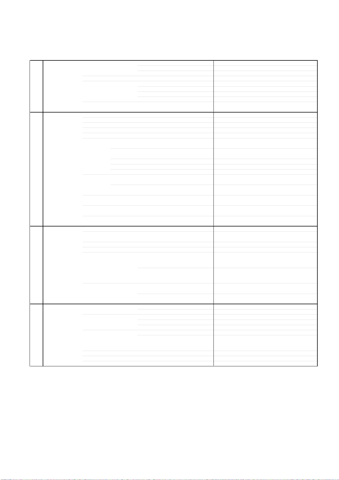
3. REMOVAL OF DVD DECK PARTS
3-1: TRAY (Refer to Fig. 3-1-A)
Set the Tray opened. (Refer to the DISC REMOVAL
METHOD AT NO POWER SUPPLY)
Unlock the 2 supports 1 and remove the Tray.
1.
2.
Fig. 3-1-A
Tray
Main Frame Ass'y
1
NOTE
1.
In case of the Tray installation, install them as the circled
section of Fig. 3-1-B so that the each markers are met.
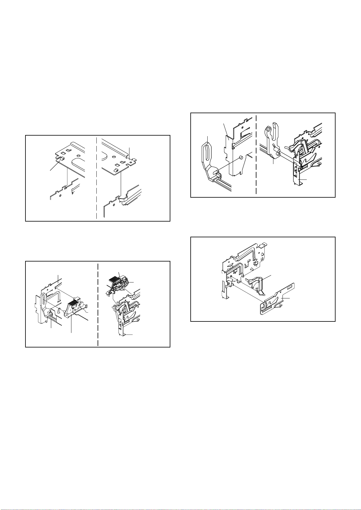
3-2: MAIN CHASSIS ASS'Y (Refer to Fig. 3-2-A)
Remove the screw 1.
Unlock the 2 supports 2.
Remove the Insulator (R) from the Main Frame Ass'y.
Remove the Main Chassis Ass'y.
1.
2.
3.
4.
Fig. 3-2-A
Tray
Main Frame Ass'y
Fig. 3-1-B
Insulator (R)
NOTE
1. Do not disassemble the DVD DECK PARTS except listed
parts here. Minute adjustments are needed if the
disassemble is done. If the repair is needed except listed
parts, replace the DVD MECHA ASS'Y.
1
1
2
Main Frame Ass'y
Main Chassis Ass'y
2
• Screw Torque: 2.0 ± 0.5kgf•cm
NOTE
1.
2.
In case of the Main Chassis Ass'y, install it from (1) to (4)
in order. (Refer to Fig. 3-2-B)
In case of the Main Chassis Ass'y installation, hook the
wire on the Main Frame Ass'y as shown Fig. 3-2-C.
Fig. 3-2-B
Fig. 3-2-C
(1)
(2)
(3)
(3)
(4)
(3)
Check Lock
(4)
Main Chassis Ass'y
Rack Loading
Main Frame Ass'y (Bottom Side)
Traverse Holder

DISASSEMBLY INSTRUCTIONS
B3-2
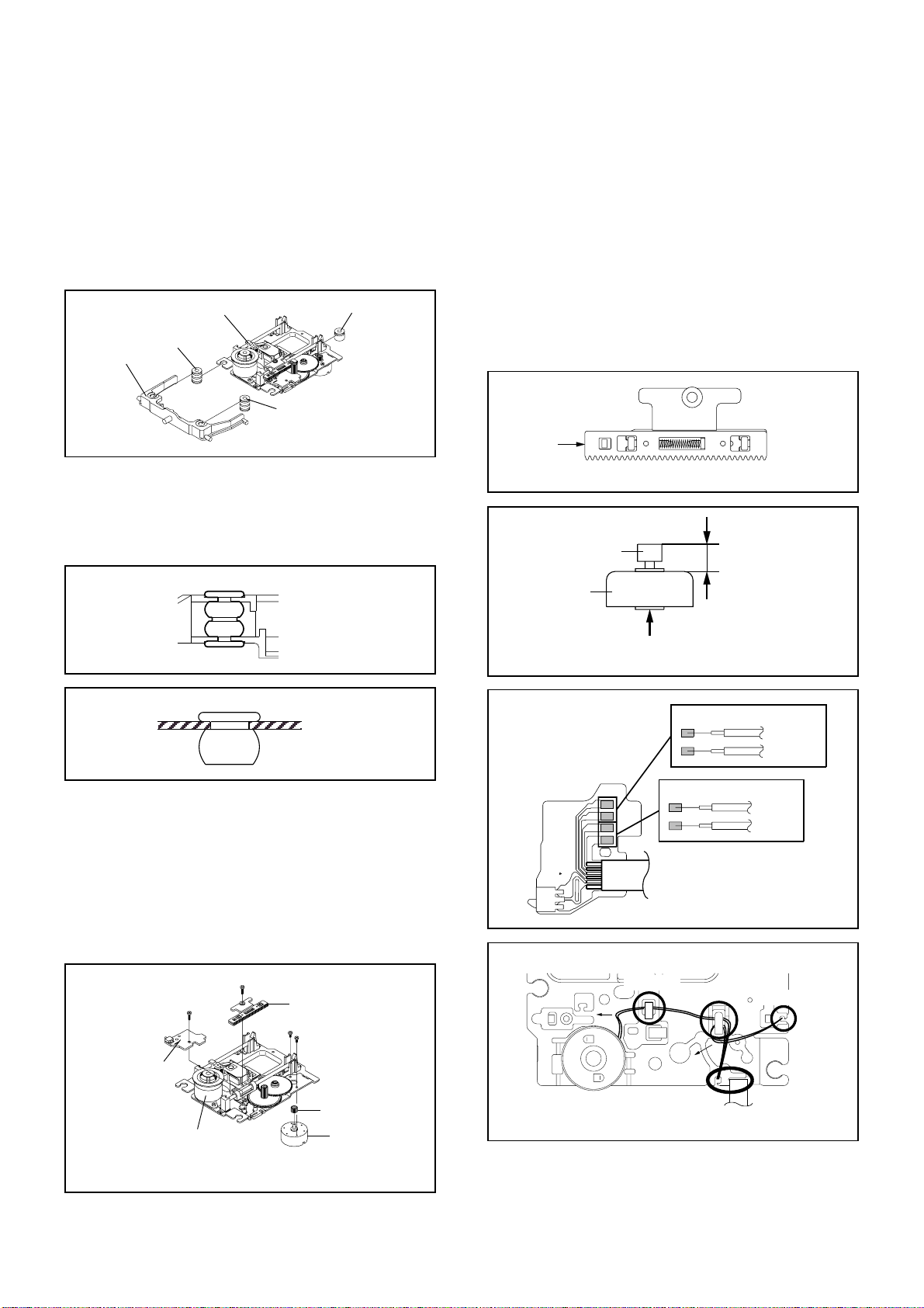
NOTE
1.
2.
3.
In case of the Pulley Motor installation, check if the value
of the Fig. 3-3-B is correct.
When installing the Loading Motor PCB Ass'y, install it
correctly as Fig. 3-3-C.
In case of the Loading Motor PCB Ass'y installation, hook
the wire on the Main Frame Ass'y as shown Fig. 3-3-C.
Fig. 3-3-B
7.0 ± 0.1mm
Safety surface for pressing
of the insert.
Loading Motor
Pulley Motor
Fig. 3-3-C
Rack Loading
AB
The Lever should be position
between A and B.
Check Hook
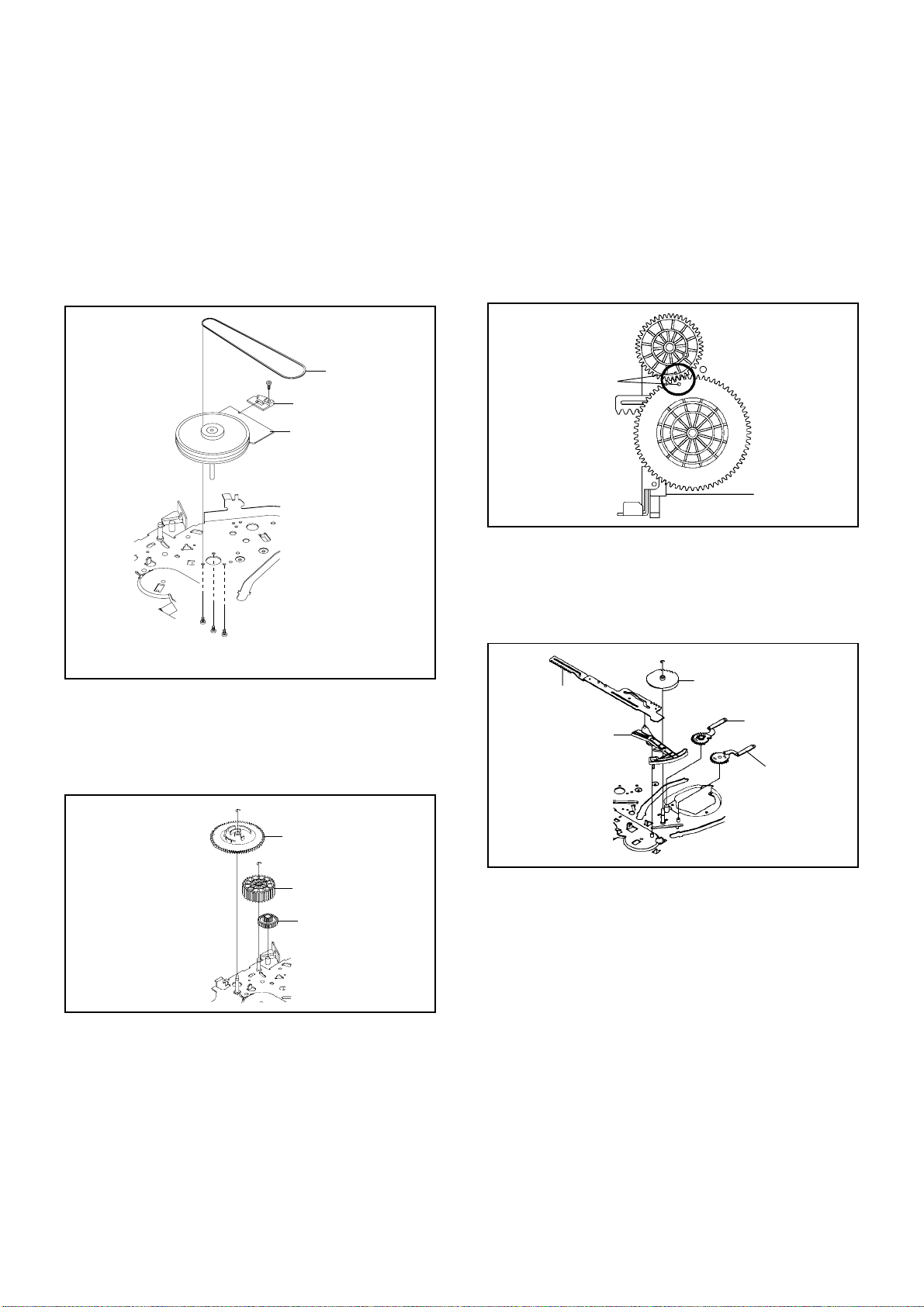
3-4: RACK LOADING/MAIN GEAR/PULLEY GEAR
(Refer to Fig. 3-4-A)
1.
2.
3.
Press down the catcher 1 and slide the Rack Loading.
Unlock the support 2 and remove the Pulley Gear.
Remove the Main Gear.
Loading Motor PCB Ass’y
Loading Belt
Pulley Gear
1
Main Frame Ass’y
3-3: LOADING MOTOR PCB ASS'Y/ LOADING BELT
(Refer to Fig. 3-3-A)
1.
2.
3.
4.
5.
Remove the Loading Belt.
Remove the screw 1.
Remove the 2 screws 2.
Remove the Loading Motor PCB Ass'y.
Remove the Pulley Gear.
Fig. 3-3-A
2
2
Loading Motor PCB Ass’y
• Screw Torque: 2.5 ± 0.3kgf•cm (Screw 1)
• Screw Torque: 1.0 ± 0.3kgf•cm (Screw 2)
Rack Loading
1
Main Frame Ass’y
Main Gear
Pulley Gear
2
Fig. 3-4-A
Fig. 3-4-B
NOTE
1. In case of the Rack Loading installation, do not mesh it
to the Main Gear as shown the Fig. 3-4-B.
Check Hook
Main Gear
Rack Loading
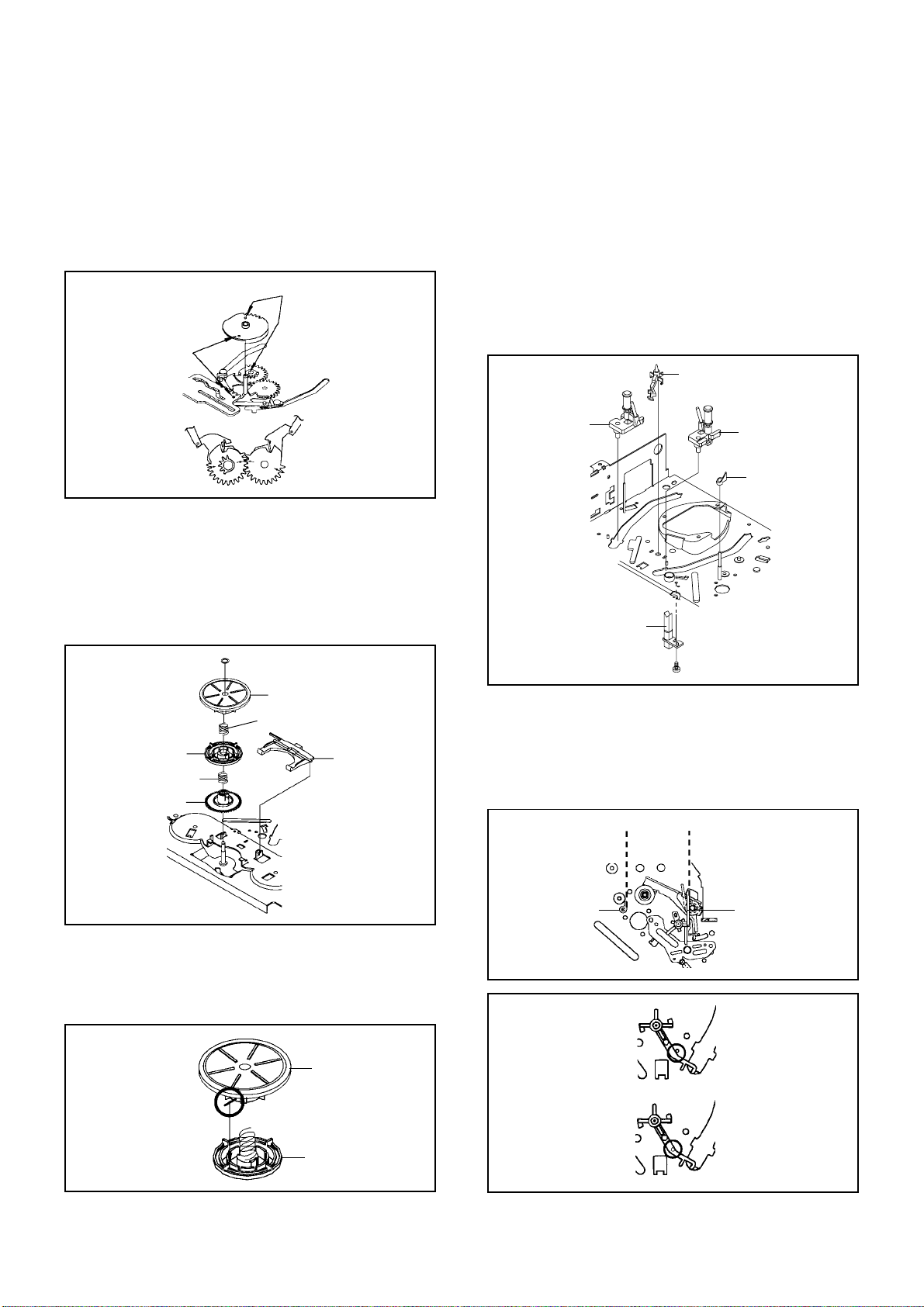
3-5: CLAMPER ASS'Y (Refer to Fig. 3-5-A)
Press the Clamper and rotate the Clamper Plate
clockwise, then unlock the 3 supports 1.
Remove the Clamper Plate, Clamper Magnet and
Clamper.
1.
2.
Clamper Plate
Clamper Magnet
Fig. 3-5-A
Main Frame
Clamper
1
1
1
NOTE
1. In case of the Clamper Ass'y installation, install correctly
as Fig. 3-5-B.
Fig. 3-5-B
No gap
Clamper Plate
Clamper
DISASSEMBLY INSTRUCTIONS
B3-3
Fig. 3-6-C
Insulator (R)
Main Chassis Ass'y (Top Side)
3-7:
Remove the screw 1.
Remove the Rack Feed Ass'y.
Remove the screw 2.
Remove the Switch PCB Ass'y.
Remove the 2 screw 3.
Remove the Feed Motor.
Remove the Motor Gear.
1.
2.
3.
4.
5.
6.
7.
RACK FEED ASS'Y/SWITCH PCB ASS'Y/FEED
MOTOR (Refer to Fig. 3-7-A)
Traverse Holder
Insulator (F)
Main Chassis Ass'y
Insulator (F)
Insulator (R)
3-6:
Remove the Traverse Holder.
Remove the 2 Insulator (F).
Remove the Insulator (R).
1.
2.
3.
Fig. 3-6-A
TRAVERSE HOLDER/INSULATOR (F)/INSULATOR
(R) (Refer to Fig. 3-6-A)
NOTE
1.
2.
In case of the Insulator (F) installation, install correctly as
Fig. 3-6-B.
In case of the Insulator (R) installation, install correctly as
Fig. 3-6-C.
Fig. 3-6-B
Traverse Holder
Insulator (F)
Fig. 3-7-C
6.0 ± 0.2mm
Safety surface for pressing
of the insert.
Feed Motor
Motor Gear
NOTE
1.
2.
3.
4.
When pushing the Rack Feed in the direction of the
arrow, it should be restored to the original position by the
spring force. (Refer to Fig. 3-7-B)
In case of the Motor Gear installation, check if the value
of the Fig. 3-7-C is correct.
When installing the wire of the Switch PCB Ass'y, install it
correctly as Fig. 3-7-D.
After the assembly of the Main Chassis Ass'y, hook the
wire on the Main Chassis Ass'y as shown Fig. 3-7-E.
Fig. 3-7-B
Push
Rack Feed Ass'y
~ FEED MOTOR ~
BLUE (4)
ORANGE (3)
~ SPINDLE MOTOR ~
BLACK (2)
RED (1)
Fig. 3-7-D
Switch PCB Ass'y
• Install wire from (1) to (4) in order.
Main Chassis Ass'y (Bottom Side)
Check Hook
Check Hook
Fig. 3-7-E
Check Hook
Check Hook
• Loosen the wire in the direction of the arrow.
Fig. 3-7-A
• Screw Torque: 5.0 ± 0.3kgf•cm (Screw 1)
• Screw Torque: 3.0 ± 0.3kgf•cm (Screw 2)
• Screw Torque: 1.0 ± 0.3kgf•cm (Screw 3)
Main Chassis Ass'y
1
Rack Feed Ass'y
2
Switch PCB Ass'y
3
3
Motor Gear
Feed Motor

DISASSEMBLY INSTRUCTIONS
B3-4
Printing Surface
Reinforcement Plate
59 ± 1mm
Fold
(1)
Printing Surface
10 ± 1mm
Fold
(3)
Printing Surface
44 ± 1mm
Fold
(4)
Printing Surface
Printing Surface
10 ± 1mm
Fold
(2)
Reinforcement Plate
Reinforcement Plate
Printing Surface
Fold
43 ± 1mm
54 ± 1mm
Printing Surface
Pick Up Side
Fold it by 90˚
[ 24 pin FFC ]
When installing the FFC, fold it correctly and install it as
shown from Fig. 3-8-A to Fig. 3-8-C.
3-8: FFC WIRE HANDLING
1.
Do not make the folding lines except the specified
positions for the FFC.
1.
NOTE
Fig. 3-8-A
• Proceed the steps (1) through (4).
[ 6 pin FFC ]
Fig. 3-8-B
Printing Surface
Reinforcement Plate
55 ± 1mm
Fold
(1)
Printing Surface
10 ± 1mm
Fold
(3)
Printing Surface
60 ± 1mm
Fold
(4)
Printing Surface
Printing Surface
10 ± 1mm
Fold
(2)
Reinforcement Plate
Reinforcement Plate
• Proceed the steps (1) through (4).
[ 5 pin FFC ]
Fig. 3-8-C
 Loading...