


 Loading...
FILE NO. A03-009
SERVICE MANUAL
Indoor Unit
<4-way Air Discharge Cassette Type>
MMU-AP0091H, AP0121H, AP0151H, MMU-AP0181H, AP0241H, AP0271H, MMU-AP0301H, AP0361H, AP0481H MMU-AP0561H
<2-way Air Discharge Cassette Type>
MMU-AP0071WH, AP0091WH, AP0121WH, MMU-AP0151WH, AP0181WH, AP0241WH, MMU-AP0271WH, AP0301WH
MMU-AP0481WH (CHINA market only)
<1-way Air Discharge Cassette Type>
MMU-AP0071YH, AP0091YH, AP0121YH, MMU-AP0151SH, AP0181SH, AP0241SH
<Concealed Duct Standard Type>
MMD-AP0071BH, AP0091BH, AP0121BH, MMD-AP0151BH, AP0181BH, AP0241BH, MMD-AP0271BH, AP0301BH, AP0361BH, MMD-AP0481BH, AP0561BH
<Concealed Duct High Static Pressure Type>
MMD-AP0181H, AP0241H, AP0271H, MMD-AP0361H, AP0481H, AP0721H, MMD-AP0961H
<Under Ceiling Type>
MMC-AP0151H, AP0181H, AP0241H, MMC-AP0271H, AP0361H, AP0481H
<High Wall Type>
MMK-AP0071H, AP0091H, AP0121H, MMK-AP0151H, AP0181H, AP0241H
<Floor Standing Cabinet Type>
MML-AP0071H, AP0091H, AP0121H, MML-AP0151H, AP0181H, AP0241H
<Floor Standing Concealed Type>
MML-AP0071BH, AP0091BH, AP0121BH, MML-AP0151BH, AP0181BH, AP0241BH
<Floor Standing Type>
MMF-AP0151H, AP0181H, AP0241H MMF-AP0271H, AP0361H, AP0481H MMF-AP0561H
Outdoor Unit
Cooling Only Model
<Inverter Unit>
MMY-MAP0501T8, MAP0601T8 MMY-MAP0801T8, MAP1001T8 MMY-MAP1201T8
Heat Pump Model
<Inverter Unit>
MMY-MAP0501HT8, MAP0601HT8 MMY-MAP0801HT8, MAP1001HT8 MMY-MAP1201HT8
Heat Pump Model
<Inverter Unit>
MMY-MAP0501HT7, MAP0601HT7 MMY-MAP0801HT7, MAP1001HT7 MMY-MAP1201HT7
PRINTED IN JAPAN, May.,2004 ToMo
WARNINGS ON REFRIGERANT LEAKAGE
Check of Concentration Limit
The room in which the air conditioner is to be installed requires a design that in the event of refrigerant gas leaking out, its concentration will not exceed a set limit.
The refrigerant R410A which is used in the air conditioner is safe, without the toxicity or combustibility of ammonia, and is not restricted by laws to be imposed which protect the ozone layer. However, since it contains more than air, it poses the risk of suffocation if its concentration should rise excessively. Suffocation from leakage of R410A is almost non-existent. With the recent increase in the number of high concentration buildings, however, the installation of multi air conditioner systems is on the increase because of the need for effective use of floor space, individual control, energy conservation by curtailing heat and carrying power etc.
Most importantly, the multi air conditioner system is able to replenish a large amount of refrigerant compared with conventional individual air conditioners. If a single unit of the multi conditioner system is to be installed in a small room, select a suitable model and installation procedure so that if the refrigerant accidentally leaks out, its concentration does not reach the limit (and in the event of an emergency, measures can be made before injury can occur).
In a room where the concentration may exceed the limit, create an opening with adjacent rooms, or install mechanical ventilation combined with a gas leak detection device.
The concentration is as given below.
Total amount of refrigerant (kg)
Min. volume of the indoor unit installed room (m³) ≤ Concentration limit (kg/m³)
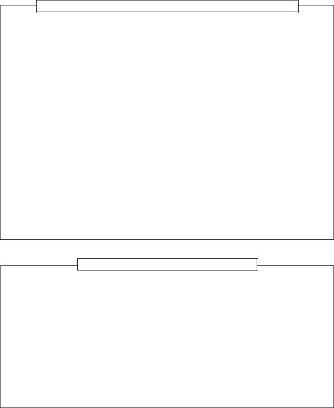
The concentration limit of R410A which is used in multi air conditioners is 0.3kg/m³.
NOTE 1 :
If there are 2 or more refrigerating systems in a single refrigerating device, the amounts of refrigerant should be as charged in each independent device.
Outdoor unit
e.g., charged
amount (10kg) 
 e.g.,
e.g.,
charged amount (15kg)
Room A Room B Room C Room D Room E Room F
Indoor unit
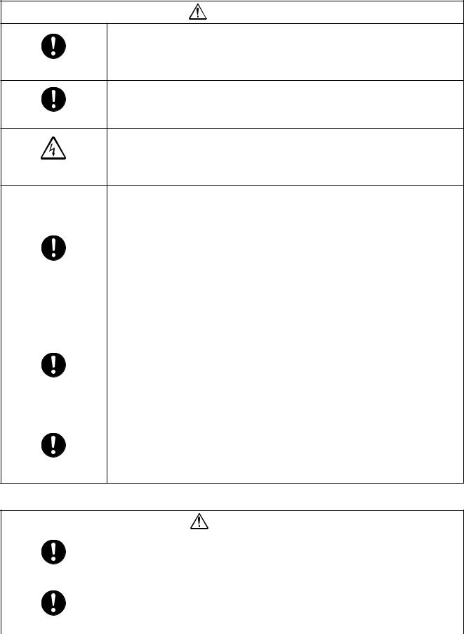
For the amount of charge in this example:
The possible amount of leaked refrigerant gas in rooms A, B and C is 10kg.
The possible amount of leaked refrigerant gas in rooms D, E and F is 15kg.
Important
NOTE : 2
The standards for minimum room volume are as follows.
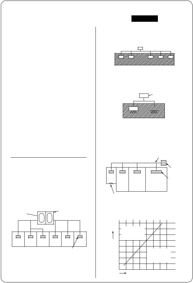
(1) No partition (shaded portion)
(2)When there is an effective opening with the adjacent room for ventilation of leaking refrigerant gas (opening without a door, or an opening 0.15% or larger than the respective floor spaces at the top or bottom of the door).
Outdoor unit
 Refrigerant piping

 Indoor unit
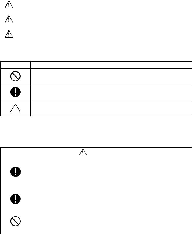
(3)If an indoor unit is installed in each partitioned room and the refrigerant tubing is interconnected, the smallest room of course becomes the object. But when a mechanical ventilation is installed interlocked with a gas leakage detector in the smallest room where the density limit is exceeded, the volume of the next smallest room becomes the object.
|
|
Refrigerant piping |
|
|
|
Outdoor unit |
|
Very |
|
|
|
small |
|
Indoor unit |
|
room |
|
||
Small |
Medium |
Large room |
|
room |
room |
||
|
Mechanical ventilation device - Gas leak detector
NOTE 3 :
The minimum indoor floor area compared with the amount of refrigerant is roughly as follows: (When the ceiling is 2.7m high)
|
40 |
|
|
|
|
m² 35 |
Range below the |
|
|
|
|
density limit |
|
|
|
||
|
30 |
of 0.3 kg/m³ |
|
|
|
|
(countermeasures |
|
|
|
|
|
|
|
|
|
|
|
25 |
not needed) |
|
|
|
area |
|
|
|
|
|
20 |
|
|
|
|
|
floor |
15 |
|
Range above |
|
|
|
the density limit |
|
|||
indoor |
10 |
|
of 0.3 kg/m³ |
|
|
|
(countermeasures |
|
|||
|
|
needed) |
|
|
|
Min. |
5 |
|
|
|
|
|
|
|
|
||
0 |
|
|
|
|
|
|
10 |
20 |
30 |
|
|
|
|
|
|||
|
|
Total amount of refrigerant |
kg |
||

NOTE
A direct current motor is adopted for indoor fan motor in the Concealed Duct Standard Type air conditioner. Caused from its characteristics, a current limit works on the direct current motor. When replacing the highperformance filter or when opening the service board, be sure to stop the fan. If an above action is executed during the fan operation, the protective control works to stop the unit operation, and the check code “P12” may be issued. However it is not a trouble. When the desired operation has finished, be sure to reset the system to clear “P12” error code using the leak breaker of the indoor unit. Then push the operation stop button of the remote controller to return to the usual operation.
|
CONTENTS |
|
SAFETY CAUTION ............................................................................................ |
4 |
|
1. |
OUTLINE .................................................................................................. |
10 |
2. |
WIRING DIAGRAM ................................................................................... |
13 |
3. |
PARTS RATING ........................................................................................ |
26 |
4. |
REFRIGERANT PIPING SYSTEMATIC DRAWING ................................. |
56 |
5. |
COMBINED REFRIGERANT PIPES SYSTEMATIC DRAWING .............. |
59 |
6. |
CONTROL OUTLINE ................................................................................ |
64 |
7. |
APPLIED CONTROL ................................................................................ |
74 |
8. |
TEST OPERATION ................................................................................... |
88 |
9. |
TROUBLESHOOTING ............................................................................ |
128 |
10. |
CONFIGURATION OF CONTROL CIRCUIT .......................................... |
214 |
11. |
BACKUP OPERATIONS (EMERGENCY OPERATION) ........................ |
228 |
12. |
OIL LEVEL JUDGMENT DISPLAY ........................................................ |
233 |
13. |
REFRIGERANT RECOVERY |
|
|
WHEN REPLACING THE COMPRESSOR ............................................ |
234 |
14. |
LEAKAGE/CLOGGING OF OIL-EQUALIZATION CIRCUIT .................. |
240 |
15. |
REPLACING COMPRESSOR ................................................................ |
242 |
16. |
REOLACING METHOD OF PARTS ....................................................... |
249 |
17. |
P.C. BOARD EXCHANGE PROCEDURES ............................................ |
259 |
SAFETY CAUTION
The important contents concerned to the safety are described on the product itself and on this Service Manual.
Please read this Service Manual after understanding the described items thoroughly in the following contents (Indications/Illustrated marks), and keep them.
[Explanation of indications]
Indication |
Explanation |
|
|
DANGER |
Indicates contents assumed that an imminent danger causing a death or serious injury of |
the repair engineers and the third parties when an incorrect work has been executed. |
|
|
|
WARNING |
Indicates possibilities assumed that a danger causing a death or serious injury of the |
repair engineers, the third parties, and the users due to troubles of the product after work |
|
|
when an incorrect work has been executed. |
|
|
CAUTION |
Indicates contents assumed that an injury or property damage ( ) may be caused on the |
repair engineers, the third parties, and the users due to troubles of the product after work |
|
|
when an incorrect work has been executed. |
|
|
Property damage : Enlarged damage concerned to property, furniture, and domestic animal/pet
[Explanation of illustrated marks]
Mark |
Explanation |
Indicates prohibited items (Forbidden items to do)
The sentences near an illustrated mark describe the concrete prohibited contents.
Indicates mandatory items (Compulsory items to do)
The sentences near an illustrated mark describe the concrete mandatory contents.
Indicates cautions (including danger/warning)
The sentences or illustration near or in an illustrated mark describe the concrete cautious contents.
[Confirmation of warning label on the main unit]
Confirm that labels are indicated on the specified positions (Refer to the Parts disassembly diagram (Outdoor unit).)
If removing the label during parts replace, stick it as the original.
DANGER
|
Turn “OFF” the breaker before removing the front panel and cabinet, otherwise an electric |
|
|
shock is caused by high voltage resulted in a death or injury. |
|
|
During operation, a high voltage with 400V or higher of circuit ( ) at secondary circuit of the high- |
|
|
voltage transformer is applied. |
|
Turn off breaker. |
If touching a high voltage with the naked hands or body, an electric shock is caused even if using an |
|
electric insulator. |
||
|
||
|
: For details, refer to the electric wiring diagram. |
|
|
|
|
|
When removing the front panel or cabinet, execute short-circuit and discharge between high- |
|
|
voltage capacitor terminals. |
|
Execute discharge |
If discharge is not executed, an electric shock is caused by high voltage resulted in a death or injury. |
|
After turning off the breaker, high voltage also keeps to apply to the high-voltage capacitor. |
||
between terminals. |
||
|
||
|
|
|
|
Do not turn on the breaker under condition that the front panel and cabinet are removed. |
|
|
An electric shock is caused by high voltage resulted in a death or injury. |
|
Prohibition |
|
|
|
|
4

WARNING
|
Before troubleshooting or repair work, check the earth wire is connected to the earth |
|
|
terminals of the main unit, otherwise an electric shock is caused when a leak occurs. |
|
Check earth wires. |
If the earth wire is not correctly connected, contact an electric engineer for rework. |
|
|
||
|
|
|
|
Do not modify the products. |
|
|
Do not also disassemble or modify the parts. It may cause a fire, electric shock or injury. |
|
Prohibition of modification. |
|
|
|
|
|
|
For spare parts, use those specified ( ). |
|
|
If unspecified parts are used, a fire or electric shock may be caused. |
|
Use specified parts. |
: For details, refer to the parts list. |
|
|
|
|
|
Before troubleshooting or repair work, do not bring a third party (a child, etc.) except |
|
|
the repair engineers close to the equipment. |
|
Do not bring a child |
It causes an injury with tools or disassembled parts. |
|
Please inform the users so that the third party (a child, etc.) does not approach the equipment. |
||
close to the equipment. |
||
|
|
|
|
Connect the cut-off lead cables with crimp contact, etc, put the closed end side |
|
|
upward and then apply a water-cut method, otherwise a leak or production of fire is |
|
|
caused at the users’ side. |
|
Insulating measures |
|
When repairing the refrigerating cycle, take the following measures.
1)Be attentive to fire around the cycle. When using a gas stove, etc, be sure to put out fire before work; otherwise the oil mixed with refrigerant gas may catch fire.
2) |
Do not use a welder in the closed room. When using it without ventilation, carbon |
No fire |
monoxide poisoning may be caused. |
3)Do not bring inflammables close to the refrigerant cycle, otherwise fire of the welder may catch the inflammables.
Check the used refrigerant name and use tools and materials of the parts which match with it.
For the products which use R410A refrigerant, the refrigerant name is indicated at a position on the outdoor unit where is easy to see. To prevent miss-charging, the route of the service port is changed from one of the former R22.
|
For an air conditioner which uses R410A, never use other refrigerant than R410A. |
|
|
For an air conditioner which uses other refrigerant (R22, etc.), never use R410A. |
|
|
If different types of refrigerant are mixed, abnormal high pressure generates in the refriger- |
|
|
ating cycle and an injury due to breakage may be caused. |
|
|
Do not charge refrigerant additionally. |
|
|
If charging refrigerant additionally when refrigerant gas leaks, the refrigerant composition in |
|
|
the refrigerating cycle changes resulted in change of air conditioner characteristics or |
|
|
refrigerant over the specified standard amount is charged and an abnormal high pressure is |
|
|
applied to the inside of the refrigerating cycle resulted in cause of breakage or injury. |
|
|
Therefore if the refrigerant gas leaks, recover the refrigerant in the air conditioner, execute |
|
Refrigerant |
vacuuming, and then newly recharge the specified amount of liquid refrigerant. In this time, |
|
|
never charge the refrigerant over the specified amount. |
|
|
When recharging the refrigerant in the refrigerating cycle, do not mix the refrigerant |
|
|
or air other than R410A into the specified refrigerant. |
|
|
If air or others is mixed with the refrigerant, abnormal high pressure generates in the |
|
|
refrigerating cycle resulted in cause of injury due to breakage. |
|
|
After installation work, check the refrigerant gas does not leak. |
|
|
If the refrigerant gas leaks in the room, poisonous gas generates when gas touches to fire |
|
|
such as fan heater, stove or cocking stove though the refrigerant gas itself is innocuous. |
|
|
Never recover the refrigerant into the outdoor unit. |
|
|
When the equipment is moved or repaired, be sure to recover the refrigerant with recover- |
|
|
ing device. The refrigerant cannot be recovered in the outdoor unit; otherwise a serious |
|
|
accident such as breakage or injury is caused. |
|
|
|
|
|
After repair work, surely assemble the disassembled parts, and connect and lead the |
|
|
removed cables as before. Perform the work so that the cabinet or panel does not |
|
|
catch the inner cables. |
|
Assembly/Cabling |
If incorrect assembly or incorrect cable connection was done, a disaster such as a leak or |
|
fire is caused at user’s side. |
||
|
5
WARNING
|
After the work has finished, be sure to use an insulation tester set (500V mugger) to |
|
|
check the resistance is 2MΩ or more between the charge section and the non-charge |
|
|
metal section (Earth position). |
|
Insulator check |
If the resistance value is low, a disaster such as a leak or electric shock is caused at user’s |
|
side. |
||
|
When the refrigerant gas leaks during work, execute ventilation.
|
If the refrigerant gas touches to a fire, poisonous gas generates. A case of leakage of the |
|
refrigerant and the closed room full with gas is dangerous because a shortage of oxygen |
Ventilation |
occurs. Be sure to execute ventilation. |
When checking the circuit inevitably under condition of the power-ON, use rubber gloves and others not to touch to the charging section.
If touching to the charging section, an electric shock may be caused.
Be attentive to electric shock
When the refrigerant gas leaks, find up the leaked position and repair it surely.
If the leaked position cannot be found up and the repair work is interrupted, pump-down and tighten the service valve, otherwise the refrigerant gas may leak into the room.
The poisonous gas generates when gas touches to fire such as fan heater, stove or cocking stove though the refrigerant gas itself is innocuous.
|
When installing equipment which includes a large amount of charged refrigerant such |
|
as a multi air conditioner in a sub-room, it is necessary that the density does not the |
Compulsion |
limit even if the refrigerant leaks. |
If the refrigerant leaks and exceeds the limit density, an accident of shortage of oxygen is caused.
|
For the installation/moving/reinstallation work, follow to the Installation Manual. |
|
|
If an incorrect installation is done, a trouble of the refrigerating cycle, water leak, electric |
|
|
shock or fire is caused. |
|
|
|
|
|
After repair work has finished, check there is no trouble. |
|
|
If check is not executed, a fire, electric shock or injury may be caused. For a check, turn off |
|
|
the power breaker. |
|
|
|
|
Check after rerair |
After repair work (installation of front panel and cabinet) has finished, execute a test |
|
run to check there is no generation of smoke or abnormal sound. |
||
|
||
|
If check is not executed, a fire or an electric shock is caused. Before test run, install the |
|
|
front panel and cabinet. |
|
|
|
|
|
Check the following items after reinstallation. |
|
|
1) The earth wire is correctly connected. |
|
|
2) The power cord is not caught in the product. |
|
Check after reinstallation |
3) There is no inclination or unsteadiness and the installation is stable. |
|
If check is not executed, a fire, an electric shock or an injury is caused. |
||
|
CAUTION
|
Be sure to put on gloves ( ) during repair work. |
|
If not putting on gloves, an injury may be caused with the parts, etc. |
Put on gloves |
( ) Heavy gloves such as work gloves |
|
|
|
|
|
When the power was turned on, start to work after the equipment has been |
|
sufficiently cooled. |
Cooling check |
As temperature of the compressor pipes and others became high due to cooling/heating |
operation, a burn may be caused. |
|
|
|
6

• New Refrigerant (R410A)
This air conditioner adopts a new HFC type refrigerant (R410A) which does not deplete the ozone layer.
1. Safety Caution Concerned to New Refrigerant
The pressure of R410A is high 1.6 times of that of the former refrigerant (R22). Accompanied with change of refrigerant, the refrigerating oil has been also changed. Therefore, be sure that water, dust, the former refrigerant or the former refrigerating oil is not mixed into the refrigerating cycle of the air conditioner with new refrigerant during installation work or service work. If an incorrect work or incorrect service is performed, there is a possibility to cause a serious accident. Use the tools and materials exclusive to R410A to purpose a safe work.
2. Cautions on Installation/Service
(1)Do not mix the other refrigerant or refrigerating oil.
For the tools exclusive to R410A, shapes of all the joints including the service port differ from those of the former refrigerant in order to prevent mixture of them.
(2)As the use pressure of the new refrigerant is high, use material thickness of the pipe and tools which are specified for R410A.
(3)In the installation time, use clean pipe materials and work with great attention so that water and others do not mix in because pipes are affected by impurities such as water, oxide scales, oil, etc. Use the clean pipes.
Be sure to brazing with flowing nitrogen gas. (Never use gas other than nitrogen gas.)
(4)For the earth protection, use a vacuum pump for air purge.
(5)R410A refrigerant is azeotropic mixture type refrigerant. Therefore use liquid type to charge the refrigerant. (If using gas for charging, composition of the refrigerant changes and then characteristics of the air conditioner change.)
3. Pipe Materials
For the refrigerant pipes, copper pipe and joints are mainly used. It is necessary to select the most appropriate pipes to conform to the standard. Use clean material in which impurities adhere inside of pipe or joint to a minimum.
(1) Copper pipe
<Piping>
The pipe thickness, flare finishing size, flare nut and others differ according to a refrigerant type.
When using a long copper pipe for R410A, it is recommended to select “Copper or copper-base pipe without seam” and one with bonded oil amount 40mg/10m or less. Also do not use crushed, deformed, discolored (especially inside) pipes. (Impurities cause clogging of expansion valves and capillary tubes.)
<Flare nut>
Use the flare nuts which are attached to the air conditioner unit.
(2)Joint
The flare joint and socket joint are used for joints of the copper pipe. The joints are rarely used for installation of the air conditioner. However clear impurities when using them.
7
4. Tools
(1)Required Tools for R410A
Mixing of different types of oil may cause a trouble such as generation of sludge, clogging of capillary, etc. Accordingly, the tools to be used are classified into the following three types.
1)Tools exclusive for R410A (Those which cannot be used for conventional refrigerant (R22))
2)Tools exclusive for R410A, but can be also used for conventional refrigerant (R22)
3)Tools commonly used for R410A and for conventional refrigerant (R22)
The table below shows the tools exclusive for R410A and their interchangeability.
Tools exclusive for R410A (The following tools for R410A are required.)
Tools whose specifications are changed for R410A and their interchangeability
|
|
|
|
R410A |
Conventional air |
|
|
|
|
air conditioner installation |
conditioner installation |
||
No. |
Used tool |
Usage |
|
|
|
|
Existence of |
|
Whether conven- |
Whether new equipment |
|||
|
|
|
|
|||
|
|
|
new equipment |
|
tional equipment can |
can be used with |
|
|
|
for R410A |
|
be used |
conventional refrigerant |
|
|
|
|
|
|
|
Q |
Flare tool |
Pipe flaring |
Yes |
|
*(Note 1) |
Yes |
|
|
|
|
|
|
|
|
Copper pipe gauge for |
Flaring by conventional |
Yes |
|
*(Note 1) |
*(Note 1) |
R |
adjusting projection |
|
||||
flare tool |
|
|||||
|
margin |
|
|
|
|
|
|
|
|
|
|
|
|
|
|
|
|
|
|
|
S |
Torque wrench |
Connection of flare nut |
Yes |
|
No |
No |
|
|
|
|
|
|
|
T |
Gauge manifold |
Evacuating, refrigerant |
Yes |
|
No |
No |
|
|
|
||||
|
|
charge, run check, etc. |
|
|||
U |
Charge hose |
|
|
|
|
|
|
|
|
|
|
||
|
|
|
|
|
|
|
V |
Vacuum pump adapter |
Vacuum evacuating |
Yes |
|
No |
Yes |
|
|
|
|
|
|
|
W |
Electronic balance for |
Refrigerant charge |
Yes |
|
Yes |
Yes |
refrigerant charging |
|
|||||
|
|
|
|
|
|
|
X |
Refrigerant cylinder |
Refrigerant charge |
Yes |
|
No |
No |
|
|
|
|
|
|
|
Y |
Leakage detector |
Gas leakage check |
Yes |
|
No |
Yes |
|
|
|
|
|
|
|
Y |
Charging cylinder |
Refrigerant charge |
(Note 2) |
|
No |
No |
|
|
|
|
|
|
|
(Note 1) When flaring is carried out for R410A using the conventional flare tools, adjustment of projection margin is necessary. For this adjustment, a copper pipe gauge, etc. are necessary.
(Note 2) Charging cylinder for R410A is being currently developed.
General tools (Conventional tools can be used.)
In addition to the above exclusive tools, the following equipments which serve also for R22 are necessary as the general tools.
(1) |
Vacuum pump |
(7) |
Screwdriver (+, –) |
||
|
Use vacuum pump by |
(8) |
Spanner or Monkey wrench |
||
|
attaching vacuum pump adapter. |
||||
|
(9) |
Hole core drill |
|||
(2) |
Torque wrench |
||||
(10) |
Hexagon wrench (Opposite side 4mm) |
||||
(3) |
Pipe cutter |
||||
(11) |
Tape measure |
||||
(4) |
Reamer |
||||
(12) |
Metal saw |
||||
|
|
||||
(5)Pipe bender
(6)Level vial
Also prepare the following equipments for other installation method and run check.
(1) |
Clamp meter |
(3) |
IInsulation resistance tester |
(2) |
Thermometer |
(4) |
Electroscope |
8
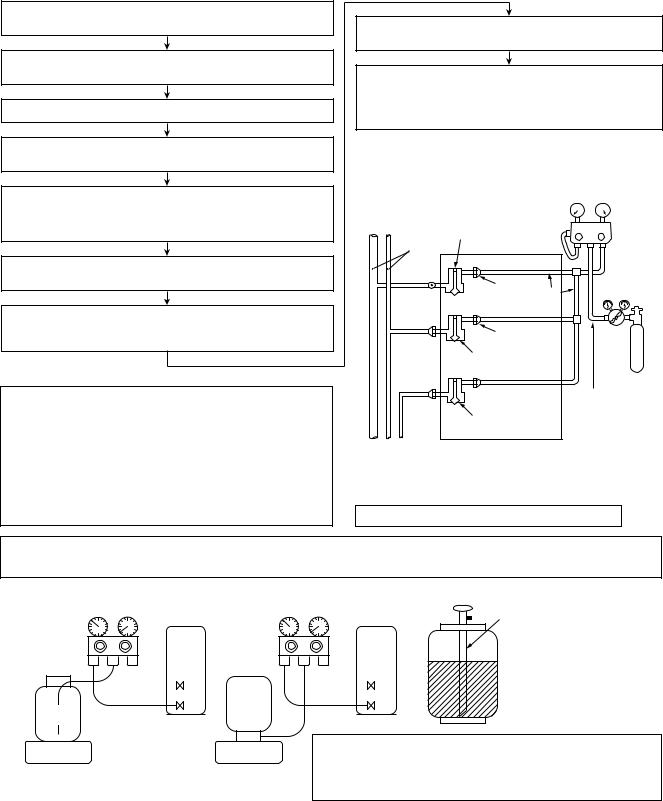
5. Recharge of Refrigerant
When recharge of the refrigerant is required, charge the new refrigerant with the specified amount in the procedure as described below.
Recover the refrigerant and check there is no refrigerant in the equipment.
Connect the charge hose to the packed valve service ports at gas side, liquid side, and balance side of the outdoor unit.
Connect the charge hose to vacuum pump adaptor.
Open the packed valves of the balance pipe fully at liquid and gas sides, and then return the valve at gas side a little to the closed side.
Open fully PMV of the outdoor unit.
•Turn on power of the outdoor unit.
•Short CN30 on I/F P.C. board of the outdoor unit.
•Turn off power of the outdoor unit within 2 minutes after short-circuiting.
Open fully the handle Low of the gauge manifold, and then turn on the power of vacuum pump for vacuuming.
When the pressure has lowered until indication of the compound gauge pointed -0.1MPa (-76cmHg), open fully the handle Low and turn off the power of vacuum pump.
Q Never charge the refrigerant over the specified amount.
RDo not charge the additional refrigerant.
If charging refrigerant additionally when refrigerant gas leaks, the refrigerant composition in the refrigerating cycle changes resulted in change of air conditioner characteristics or refrigerant over the specified standard amount is charged and an abnormal high pressure is applied to the inside of the refrigerating cycle resulted in cause of breakage or injury.
Leave it as it is for 1 to 2 minutes and check the indicator of the compound gauge does not return.
Set the refrigerant cylinder on the electron balance, connect the charge hose to connecting ports of the cylinder and the electron gauge, and then charge the liquid refrigerant from the service port at liquid side. (Shield with the gauge manifold so that refrigerant does not flow to gas side.)
(Charge the refrigerant as below.)
|
|
|
Low- |
High- |
|
|
|
pressure gauge |
pressure gauge |
||
Connected to |
Valve fully closed |
|
|
||
indoor unit |
VL |
VH Gauge |
|||
(gas side) |
|||||
Main |
|
manifold |
|||
|
Center unit |
|
|||
|
|
|
|||
pipe |
|
|
|
||
|
|
|
|
||
Brazed |
|
Service |
|
Reducing |
|
|
|
|
|||
|
|
port |
Ø6.4 |
valve |
|
Fully |
|
Copper pipe |
|
||
|
|
|
|
||
tightened |
|
|
|
||
|
|
Service port |
|
||
|
|
Valve fully closed |
|
|
|
Fully |
|
(liquid side) |
|
Nitrogen |
|
tightened |
|
|
|||
|
|
gas |
|||
|
|
|
|
||
|
|
|
Ø6.4 |
||
|
|
|
Copper pipe |
||
|
|
Valve fully closed |
|
|
|
|
|
(balance) |
|
|
|
Connected to other |
|
|
|
||
terminal units |
|
|
|
|
|
4mm-hexagonal wrench is required.
Q R
Set the equipment so that liquid refrigerant can be charged.
When using a cylinder with siphon pipe, liquid can be charged without inversing the cylinder.
[ Cylinder with siphon ] |
[ Cylinder without siphon ] |
|
Gauge manifold |
Gauge manifold |
Siphon |
OUTDOOR unit |
OUTDOOR unit |
|
Refrigerant
cylinder
cylinder Refrigerant
Electronic |
Electronic |
balance |
balance |
R410A refrigerant is consisted with HFC mixed refrigerant. Therefore if the refrigerant gas is charged, the composition of the charged refrigerant changes and characteristics of the equipment changes.
6. Environment
Use “Vacuum pump method” for an air purge (Discharge of air in the connecting pipe) in installation time.
•Do not discharge flon gas into the air to protect the earth environment.
•Using the vacuum pump method, clear the remained air (Nitrogen, etc.) in the unit. If the air remains, the pressure in the refrigerating cycle becomes abnormally high and an injury and others are caused due to burst.
9
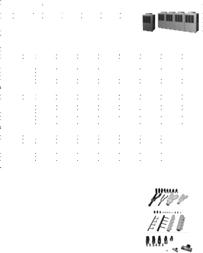
1. OUTLINE
1-1. Components Lineup in Super Modular Multi Using High-efficiency Refrigerant R410A
n Outdoor units
Corresponding HP |
|
|
|
|
Inverter unit |
|
|
|
|
Appearance |
||
|
5 HP |
6 HP |
|
8 HP |
|
10 HP |
|
12 HP |
||||
|
|
|
|
|
|
|
|
|||||
Model |
Heat pump |
MMY- |
|
MAP0501HT8 |
MAP0601HT8 |
|
MAP0801HT8 |
|
MAP1001H8 |
|
MAP1201HT8 |
|
Heat pump |
MMY- |
|
MAP0501HT7 |
MAP0601HT7 |
|
MAP0801HT7 |
|
MAP1001HT7 |
|
MAP1201HT7 |
|
|
name |
|
|
|
|
|
|||||||
|
Cooling only |
MMY- |
|
MAP0501T8 |
MAP0601T8 |
|
MAP0801T8 |
|
MAP1001T8 |
|
MAP1201T8 |
|
Cooling capacity (kW) |
|
|
14.0 |
16.0 |
|
22.4 |
|
28.0 |
|
33.5 |
|
|
Heating capacity (kW) |
|
|
16.0 |
18.0 |
|
25.0 |
|
31.5 |
|
37.5 |
|
|
No. of connectable indoor units |
|
8 |
10 |
|
13 |
|
16 |
|
20 |
|
||
n Combination of outdoor units
Corresponding HP |
14 HP |
|
16 HP |
|
18 HP |
|
20 HP |
|
22 HP |
|
22 HP |
|
24 HP |
|
24 HP |
||
|
|
MMY- |
AP1401HT8 |
|
AP1601HT8 |
|
AP1801HT8 |
|
AP2001HT8 |
|
AP2201HT8 |
|
AP2211HT8 |
|
AP2401HT8 |
|
AP2411HT8 |
Combined Model |
|
MMY- |
AP1401HT7 |
|
AP1601HT7 |
|
AP1801HT7 |
|
AP2001HT7 |
|
AP2201HT7 |
|
AP2211HT7 |
|
AP2401HT7 |
|
AP2411HT7 |
|
|
MMY- |
AP1401T8 |
|
AP1601T8 |
|
AP1801T8 |
|
AP2001T8 |
|
AP2201T8 |
|
AP2211T8 |
|
AP2401T8 |
|
AP2411T8 |
Cooling capacity (kW) |
|
38.4 |
|
45.0 |
|
50.4 |
|
56.0 |
|
61.5 |
|
61.5 |
|
68.0 |
68.0 |
||
Heating capacity (kW) |
43.0 |
|
50.0 |
|
56.5 |
|
63.0 |
|
69.0 |
|
69.0 |
|
76.5 |
76.5 |
|||
|
|
|
8 HP |
|
8 HP |
|
10 HP |
|
10 HP |
|
8 HP |
|
12 HP |
|
8 HP |
|
12 HP |
Combined outdoor units |
6 HP |
|
8 HP |
|
8 HP |
|
10 HP |
|
8 HP |
|
10 HP |
|
8 HP |
|
12 HP |
||
— |
|
— |
|
— |
|
— |
|
6 HP |
|
— |
|
8 HP |
|
— |
|||
|
|
|
|
|
|
|
|
|
|
||||||||
|
|
|
— |
|
— |
|
— |
|
— |
|
— |
|
— |
|
— |
|
— |
No. of connectable indoor units |
23 |
|
27 |
|
30 |
|
33 |
|
37 |
|
37 |
|
40 |
40 |
|||
|
|
|
|
|
|
|
|
|
|
|
|
|
|
|
|
||
Corresponding HP |
26 HP |
|
28 HP |
|
30 HP |
|
32 HP |
|
32 HP |
|
34 HP |
|
34 HP |
|
36 HP |
||
|
|
MMY- |
AP2601HT8 |
|
AP2801HT8 |
|
AP3001HT8 |
|
AP3201HT8 |
|
AP3211HT8 |
|
AP3401HT8 |
|
AP3411HT8 |
|
AP3601HT8 |
Combined Model |
|
MMY- |
AP2601HT7 |
|
AP2801HT7 |
|
AP3001HT7 |
|
AP3201HT7 |
|
AP3211HT7 |
|
AP3401HT7 |
|
AP3411HT7 |
|
AP3601HT7 |
|
|
MMY- |
AP2601T8 |
|
AP2801T8 |
|
AP3001T8 |
|
AP3201T8 |
|
AP3211T8 |
|
AP3401T8 |
|
AP3411T8 |
|
AP3601T8 |
Cooling capacity (kW) |
|
73.0 |
|
78.5 |
|
84.0 |
|
90.0 |
|
90.0 |
|
96.0 |
|
96.0 |
101.0 |
||
Heating capacity (kW) |
81.5 |
|
88.0 |
|
95.0 |
|
100.0 |
|
100.0 |
|
108.0 |
|
108.0 |
113.0 |
|||
|
|
|
10 HP |
|
10 HP |
|
10 HP |
|
8 HP |
|
12 HP |
|
10 HP |
|
12 HP |
|
10 HP |
Combined outdoor units |
8 HP |
|
10 HP |
|
10 HP |
|
8 HP |
|
10 HP |
|
8 HP |
|
12 HP |
|
10 HP |
||
8 HP |
|
8 HP |
|
10 HP |
|
8 HP |
|
10 HP |
|
8 HP |
|
10 HP |
|
8 HP |
|||
|
|
|
|
|
|
|
|
|
|
||||||||
|
|
|
— |
|
— |
|
— |
|
8 HP |
|
— |
|
8 HP |
|
— |
|
8 HP |
No. of connectable indoor units |
43 |
|
47 |
|
48 |
|
48 |
|
48 |
|
48 |
|
48 |
48 |
|||
|
|
|
|
|
|
|
|
|
|
|
|
|
|
|
|
||
Corresponding HP |
36 HP |
|
38 HP |
|
40 HP |
|
42 HP |
|
44 HP |
|
46 HP |
|
48 HP |
|
|
||
|
|
MMY- |
AP3611HT8 |
|
AP3801HT8 |
|
AP4001HT8 |
|
AP4201HT8 |
|
AP4401HT8 |
|
AP4601HT8 |
|
AP4801HT8 |
|
|
Combined Model |
|
MMY- |
AP3611HT7 |
|
AP3801HT7 |
|
AP4001HT7 |
|
AP4201HT7 |
|
AP4401HT7 |
|
AP4601HT7 |
|
AP4801HT7 |
|
|
|
|
MMY- |
AP3611T8 |
|
AP3801T8 |
|
AP4001T8 |
|
AP4201T8 |
|
AP4401T8 |
|
AP4601T8 |
|
AP4801T8 |
|
|
Cooling capacity (kW) |
|
101.0 |
|
106.5 |
|
112.0 |
|
118.0 |
|
123.5 |
|
130.0 |
|
135.0 |
|
|
|
Heating capacity (kW) |
113.0 |
|
119.5 |
|
126.5 |
|
132.0 |
|
138.0 |
|
145.0 |
|
150.0 |
|
|
||
|
|
|
12 HP |
|
10 HP |
|
10 HP |
|
12 HP |
|
12 HP |
|
12 HP |
|
12 HP |
|
|
Combined outdoor units |
12 HP |
|
10 HP |
|
10 HP |
|
10 HP |
|
12 HP |
|
12 HP |
|
12 HP |
|
|
||
12 HP |
|
10 HP |
|
10 HP |
|
10 HP |
|
10 HP |
|
12 HP |
|
12 HP |
|
|
|||
|
|
|
|
|
|
|
|
|
|
|
|||||||
|
|
|
— |
|
8 HP |
|
10 HP |
|
10 HP |
|
10 HP |
|
10 HP |
|
12 HP |
|
|
No. of connectable indoor units |
48 |
|
48 |
|
48 |
|
48 |
|
48 |
|
48 |
|
48 |
|
|
||
n Branching joints and headers
|
Model RBM- |
|
Usage |
|
External view |
|
|
|
|
|
|
|
BY53-E |
Total indoor unit capacity code |
Below 6.4 |
|
|
|
|
|
|
|
|
Y-branch joint |
BY103-E |
Total indoor unit capacity code |
Over 6.4, below 14.2 |
|
|
|
|
|
|
|
|
BY203-E |
Total indoor unit capacity code |
Over 14.2, below 25.2 |
|
||
|
|
||||
|
|
|
|
|
|
|
BY303-E |
Total indoor unit capacity code |
Over 25.2 |
|
|
|
|
|
|
|
|
|
HY1043-E |
Max. |
Total indoor unit capacity code |
Below 14.2 |
|
|
|
|
|
|
|
Branch header |
HY2043-E |
4 branches |
Total indoor unit capacity code |
Over 14.2, below 25.2 |
|
|
|
|
|
|
|
HY1083-E |
Max. |
Total indoor unit capacity code |
Below 14.2 |
|
|
|
|
||||
|
|
|
|
|
|
|
HY2083-E |
8 branches |
Total indoor unit capacity code |
Over 14.2, below 25.2 |
|
|
|
|
|
|
|
|
|
The following 3 types of T joint pipes are collected as 1 set. |
|
||
T-branch joint |
BT13-E |
• Balance pipe (Ø9.5) ×1 |
|
|
|
• Pipe at liquid side (Corresponded dia. Ø9.5 to Ø22.2) ×1 |
|
||||
|
|
|
|||
|
|
• Pipe at gas side (Corresponded dia. Ø15.9 to Ø38.1) × 1 |
|
||
|
|
|
|
|
|
*In 1 line after header branch, the maximum total capacity codes 6.0 can be connected.
*The capacity code is indicated as HP equivalent. For details, refer to “Selection of refrigerant pipe”
10
n Indoor units
Type |
Appearance |
Model name |
Capacity rank |
Capacity code |
Cooling |
Heating |
|
capacity (kW) |
capacity (kW) |
||||||
|
|
|
|
|
|||
|
|
MMU-AP0091H |
009 type |
1 |
2.8 |
3.2 |
|
|
|
MMU-AP0121H |
012 type |
1.25 |
3.6 |
4.0 |
|
|
|
MMU-AP0151H, |
015 type |
1.7 |
4.5 |
5.0 |
|
|
|
MMU-AP0181H |
018 type |
2 |
5.6 |
6.3 |
|
4-way Air Discharge |
|
MMU-AP0241H |
024 type |
2.5 |
7.1 |
8.0 |
|
Cassette Type |
|
MMU-AP0271H |
027 type |
3 |
8.0 |
|
|
|
9.0 |
||||||
|
|
MMU-AP0301H |
030 type |
3.2 |
9.0 |
|
|
|
|
10.0 |
|||||
|
|
MMU-AP0361H |
036 type |
4 |
11.2 |
|
|
|
|
12.5 |
|||||
|
|
MMU-AP0481H |
048 type |
5 |
14.0 |
16.0 |
|
|
|
MMU-AP0561H |
056 type |
6 |
16.0 |
18.0 |
|
|
|
MMU-AP0071WH |
007 type |
0.8 |
2.2 |
2.5 |
|
|
|
MMU-AP0091WH |
009 type |
1 |
2.8 |
3.2 |
|
|
|
MMU-AP0121WH |
012 type |
1.25 |
3.6 |
4.0 |
|
|
|
MMU-AP0151WH |
015 type |
1.7 |
4.5 |
5.0 |
|
2-way Air Discharge |
|
MMU-AP0181WH |
018 type |
2 |
5.6 |
6.3 |
|
Cassette Type |
|
MMU-AP0241WH |
024 type |
2.5 |
7.1 |
8.0 |
|
|
|
MMU-AP0271WH |
027 type |
3 |
8.0 |
9.0 |
|
|
|
MMU-AP0301WH |
030 type |
3.2 |
9.0 |
10.0 |
|
|
|
MMU-AP0481WH |
048 type |
5 |
14.0 |
16.0 |
|
|
|
(CHINA only) |
|||||
|
|
|
|
|
|
||
|
|
MMU-AP0071YH |
007 type |
0.8 |
2.2 |
2.5 |
|
|
|
MMU-AP0091YH |
009 type |
1 |
2.8 |
3.2 |
|
1-way Air Discharge |
|
MMU-AP0121YH |
012 type |
1.25 |
3.6 |
4.0 |
|
Cassette Type |
|
MMU-AP0151SH |
015 type |
1.7 |
4.5 |
5.0 |
|
|
|
MMU-AP0181SH |
018 type |
2 |
5.6 |
6.3 |
|
|
|
MMU-AP0241SH |
024 type |
2.5 |
7.1 |
8.0 |
|
|
|
MMD-AP0071BH |
007 type |
0.8 |
2.2 |
|
|
|
|
2.5 |
|||||
|
|
MMD-AP0091BH |
009 type |
1 |
2.8 |
|
|
|
|
3.2 |
|||||
|
|
MMD-AP0121BH |
012 type |
1.25 |
3.6 |
4.0 |
|
|
|
MMD-AP0151BH |
015 type |
1.7 |
4.5 |
5.0 |
|
Concealed Duct |
|
MMD-AP0181BH |
018 type |
2 |
5.6 |
6.3 |
|
|
MMD-AP0241BH |
024 type |
2.5 |
7.1 |
8.0 |
||
Standard Type |
|
||||||
|
MMD-AP0271BH |
|
|
|
|
||
|
027 type |
3 |
8.0 |
9.0 |
|||
|
|
||||||
|
|
MMD-AP0301BH |
030 type |
3.2 |
9.0 |
|
|
|
|
10.0 |
|||||
|
|
MMD-AP0361BH |
036 type |
4 |
11.2 |
|
|
|
|
12.5 |
|||||
|
|
MMD-AP0481BH |
048 type |
5 |
14.0 |
16.0 |
|
|
|
MMD-AP0561BH |
056 type |
6 |
16.0 |
18.0 |
|
|
|
MMD-AP0181H, |
018 type |
2 |
5.6 |
6.3 |
|
|
|
MMD-AP0241H |
024 type |
2.5 |
7.1 |
8.0 |
|
Concealed Duct |
|
MMD-AP0271H |
027 type |
3 |
8.0 |
9.0 |
|
High Static |
|
MMD-AP0361H |
036 type |
4 |
11.2 |
|
|
|
12.5 |
||||||
Pressure Type |
|
MMD-AP0481H |
048 type |
5 |
14.0 |
|
|
|
16.0 |
||||||
|
|
MMD-AP0721H |
072 type |
8 |
22.4 |
|
|
|
|
25.0 |
|||||
|
|
MMD-AP0961H |
096 type |
10 |
28.0 |
31.5 |
|
|
|
MMC-AP0151H |
015 type |
1.7 |
4.5 |
5.0 |
|
|
|
MMC-AP0181H |
018 type |
2 |
5.6 |
6.3 |
|
Under Ceiling Type |
|
MMC-AP0241H |
024 type |
2.5 |
7.1 |
8.0 |
|
|
MMC-AP0271H |
|
|
|
|
||
|
027 type |
3 |
8.0 |
9.0 |
|||
|
|
||||||
|
|
MMC-AP0361H |
036 type |
4 |
11.2 |
|
|
|
|
12.5 |
|||||
|
|
MMC-AP0481H |
048 type |
5 |
14.0 |
|
|
|
|
16.0 |
|||||
|
|
MMK-AP0071H |
007 type |
0.8 |
2.2 |
2.5 |
|
|
|
MMK-AP0091H |
009 type |
1 |
2.8 |
3.2 |
|
High Wall Type |
|
MMK-AP0121H |
012 type |
1.25 |
3.6 |
4.0 |
|
|
MMK-AP0151H |
015 type |
1.7 |
4.5 |
5.0 |
||
|
|
||||||
|
|
MMK-AP0181H |
018 type |
2 |
5.6 |
6.3 |
|
|
|
MMK-AP0241H |
024 type |
2.5 |
7.1 |
|
|
|
|
8.0 |
|||||
|
|
MML-AP0071H |
007 type |
0.8 |
2.2 |
2.5 |
|
|
|
MML-AP0091H |
009 type |
1 |
2.8 |
3.2 |
|
|
|
MML-AP0121H |
012 type |
1.25 |
3.6 |
|
|
Floor Standing |
|
4.0 |
|||||
Cabinet Type |
|
MML-AP0151H |
015 type |
1.7 |
4.5 |
5.0 |
|
|
|
MML-AP0181H |
018 type |
2 |
5.6 |
6.3 |
|
|
|
MML-AP0241H |
024 type |
2.5 |
7.1 |
8.0 |
|
|
|
MML-AP0071BH |
007 type |
0.8 |
2.2 |
|
|
|
|
2.5 |
|||||
|
|
MML-AP0091BH |
009 type |
1 |
2.8 |
|
|
|
|
3.2 |
|||||
Floor Standing |
|
MML-AP0121BH |
012 type |
1.25 |
3.6 |
4.0 |
|
Concealed Type |
|
MML-AP0151BH |
015 type |
1.7 |
4.5 |
5.0 |
|
|
|
MML-AP0181BH |
018 type |
2 |
5.6 |
|
|
|
|
6.3 |
|||||
|
|
MML-AP0241BH |
024 type |
2.5 |
7.1 |
8.0 |
|
|
|
MMF-AP0151H |
015 type |
1.7 |
4.5 |
5.0 |
|
|
|
MMF-AP0181H |
018 type |
2 |
5.6 |
6.3 |
|
|
|
MMF-AP0241H |
024 type |
2.5 |
7.1 |
8.0 |
|
Floor Standing Type |
|
MMF-AP0271H |
027 type |
3 |
8.0 |
9.0 |
|
|
|
MMF-AP0361H |
036 type |
4 |
11.2 |
12.5 |
|
|
|
MMF-AP0481H |
048 type |
5 |
14.0 |
16.0 |
|
|
|
MMF-AP0561H |
056 type |
6 |
16.0 |
18.0 |
11
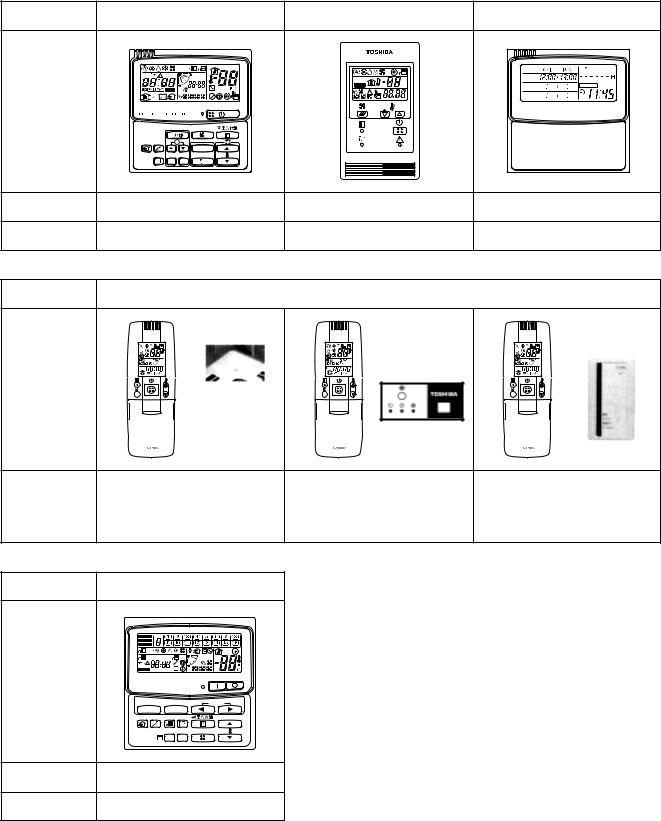
n Remote controller switch
Name |
Wired remote controller |
Simple wired remote controller |
Weekly timer |
||
|
CODE No. |
|
|
|
SuMoTuWeTh Fr Sa |
|
SET DATA |
|
|
|
|
|
UNIT No. |
TEST |
˚C |
PROGRAM1 |
|
|
|
|
|||
|
SETTINGTEST R.C. No. |
SETTING |
˚F |
PROGRAM2 |
ERROR |
|
|
|
|
|
|
|
|
|
|
PROGRAM3 |
|
Appearance |
|
|
|
WEEKLY TIMER |
|
|
UNIT |
|
|
|
|
|
SET CL |
|
|
|
|
Model name |
RBC-AMT21E |
RBC-AS21E |
RBC-EXW21E |
||
Type |
|
|
|
|
|
Name |
|
Wireless remote controller kit |
|
|
|
|
Receiver section |
|
|
|
Receiver section |
|
|
|
|
|
laid separately |
|
ADR |
ADR |
Receiver section |
ADR |
|
Appearance |
|
|
|
|
|
Model name |
RBC-AX22U (W)-E |
RBC-AX22CE |
TCB-AX21E |
|
|
|
|
|
|
Type |
Air Discharge Cassette type |
Under Ceiling type |
Separate sensor type |
|
4-way discharge type |
||||
|
|
|
Name |
Central remote controller |
||
|
ALL ZONE |
|
|
|
ZONE |
|
|
|
GROUP |
|
|
|
|
|
CODE |
|
1234 |
|
No. |
|
UNIT No. |
TEST |
|
|
|
|
|
|
SET DATA |
|
|
|
SETTING R.C. |
No. |
|
Appearance |
|
|
|
|
|
|
GROUP |
|
SELECT |
ZONE |
|
|
|
CL SET |
|
Model name |
TCB-SC642TLE |
||
Type |
64 system center controller |
||
12
13
|
|
|
|
|
|
|
|
|
|
|
|
|
|
|
PMV |
|
|
|
|
|
|
|
|
|
|
|
|
|
|
|
|
|
|
|
|
|
|
|
|
|
|
|
FM |
|
|
|
|
|
|
|
|
|
|
|
|
LM2 |
|
|
|
|
|
|
|
|
LM1 |
|
|
|
|
|
|||
|
|
|
|
|
|
|
|
|
|
|
|
|
|
|
|
|
1 |
2 |
3 |
4 |
5 |
1 |
2 |
3 |
4 |
5 |
1 |
2 |
3 |
4 |
5 |
|
|
|
||
|
|
|
|
|
|
|
|
|
|
|
|
|
|
|
|
|
|
|
|
|
|
|||||||||||||||
|
|
|
|
|
|
|
|
|
|
|
|
|
6 |
4 |
3 |
1 |
2 |
5 |
1 |
2 |
3 |
4 |
5 |
1 |
2 |
3 |
4 |
5 |
1 |
2 |
3 |
4 |
5 |
|
|
FS |
|
|
|
|
|
|
|
|
|
|
|
|
|
6 |
4 |
3 |
1 |
2 |
5 |
|
|
|
|
|
|
|
|
|
|
|
|
|
|
|
|
|
|
CN68 |
5 |
4 |
3 |
2 |
1 |
CN334 |
1 |
2 |
3 |
4 |
5 |
CN333 |
1 |
2 |
3 |
4 |
5 |
6 |
CN82 |
|
|
|
|
1 |
2 |
3 |
4 |
5 |
CN33 |
|
|
3 |
|
1 |
CN34 |
|
5 |
4 |
3 |
2 |
1 |
(BLU) |
1 |
2 |
3 |
4 |
5 |
(WHI) |
1 |
2 |
3 |
4 |
5 |
6 |
(BLU) |
|
|
|
|
1 |
2 |
3 |
4 |
5 |
(WHI) |
|
|
3 |
2 |
1 |
(RED) |
||
(BLU) |
|
|
|
|
|
|
|
|
|
|
|
|
|
|
|
|
|
|
|
|
|
|
|
|
|
|
|
|
|
|
|
|
|
|
|
|
|
|
1 |
1 |
RY302 |
|
|
|
|
CN104 |
1 |
1 |
|
DM |
|
2 2 |
|
|
|
|
|
|||||
|
|
|
|
|
|
(YEL) |
2 |
2 |
|
|||
|
|
3 |
3 |
|
|
|
|
|
TA |
|||
|
|
|
|
|
|
|
|
|
|
|||
|
|
|
|
|
|
|
|
|
CN102 |
1 |
1 |
|
|
|
|
|
|
|
Motor drive |
|
|
|
|||
|
|
|
1 |
|
|
|
|
(RED) |
2 |
2 |
|
|
|
CN304 |
RY303 |
|
circuit |
|
|
TCJ |
|||||
|
2 |
|
|
|
|
|
|
|||||
|
|
|
|
|
|
1 |
1 |
|||||
|
(GRY) |
|
|
|
|
|
CN101 |
|
||||
|
|
|
3 |
|
|
|
|
Indoor control P.C. board |
2 |
2 |
|
|
|
|
|
Fuse |
|
|
Fuse |
(BLK) |
|
||||
|
|
|
|
|
|
|
||||||
|
|
|
|
|
|
MCC-1402 |
|
|
|
TC2 |
||
|
|
|
|
T6.3A |
|
|
T3.15A |
|
1 |
1 |
||
|
RED |
|
|
250V~ |
~ |
+ |
250V~ |
|
CN100 |
|
||
|
1 |
1 |
|
Power |
DC20V |
2 |
2 |
|
||||
|
CN67 |
|
|
|
(BRN) |
|
||||||
|
2 |
2 |
|
|
|
DC15V |
3 |
3 |
TC1 |
|||
|
(BLK) |
|
|
|
supply |
DC12V |
|
|||||
|
WHI |
3 |
3 |
|
~ |
– |
circuit |
DC7V |
|
1 |
|
|
|
|
|
|
|
|
|||||||
|
|
|
|
|
|
|
|
CN80 |
PNL |
|
||
|
BLK |
|
P301 |
|
|
|
|
2 |
|
|||
Flow selector |
|
|
|
|
|
|
(GRN) |
3 |
|
|
||
|
|
|
|
|
|
|
|
|
|
|
||
unit earth |
CN66 |
1 |
|
|
|
|
|
|
1 |
|
|
|
screw |
|
|
|
|
|
CN73 |
EXCT |
|||||
|
(WHI) |
2 |
|
|
|
|
|
(RED) |
2 |
|
|
|
|
|
RED |
CN44 |
1 |
CN50 |
|
CN32 |
|
CN61 |
|
|
CN60 |
|
CN81 |
|
CN40 |
CN41 |
CN309 |
|
|
CN20 |
CN70 |
1 |
|
||||||
|
|
WHI |
|
|
|
|
|
|
|
|
Filter input |
|||||||||||||||||||
Indoor unit |
(BLN) |
2 |
(WHI) |
|
(WHI) |
|
(YEL) |
|
|
(WHI) |
|
(BLK) |
|
(BLU) |
(BLU) |
(YEL) |
|
|
|
(BLU) |
(WHI) |
2 |
||||||||
Closed end |
|
|
|
|
|
|
|
|
|
|
||||||||||||||||||||
|
R(L) S(N) |
connector |
|
1 |
2 3 4 |
5 |
1 2 |
T10 6 |
5 4 3 |
2 |
1 |
6 5 4 3 2 1 |
1 |
2 |
3 4 |
5 |
1 |
2 |
1 |
2 |
3 |
|
|
1 |
2 |
3 |
1 2 3 |
4 5 |
|
|
Earth screw |
|
|
|
|
|
(Fandrive) |
|
|
|
(Option) |
|
|
|
|
1 |
2 |
1 |
2 |
3 |
|
|
1 |
2 |
3 |
|
|
|
|
||
|
Power supply |
|
|
|
|
|
|
|
|
|
|
|
|
|
|
BLU |
BLU |
BLK |
|
BLK |
|
|
|
|
|
|
|
|
|
|
|
Single phase |
|
|
|
|
|
|
|
|
|
|
|
|
|
|
|
|
|
|
|
|
|
|
|
|
TR |
|
|
|
|
|
220-240V 50Hz |
|
|
|
|
|
|
|
|
|
|
|
|
|
|
|
|
|
|
|
|
|
|
|
|
|
|
|
||
|
|
|
|
|
|
|
|
|
|
|
|
|
|
|
|
|
|
|
|
|
|
|
|
|
|
|
|
|
||
|
220V 60Hz |
|
|
|
|
|
|
|
|
|
|
|
|
|
|
|
|
|
|
|
|
|
|
|
|
|
|
|
|
|
|
Color identification |
|
|
|
|
|
|
|
|
|
|
|
A B |
|
|
|
|
|
|
CN01 |
1 |
2 |
Network adaptor |
|
|
|||||
|
|
|
|
|
|
|
|
|
|
1 |
2 |
|
|
|
|
|
|
(WHI) |
1 |
2 |
(Option) |
|
|
|
||||||
RED : RED |
BLK : BLACK |
|
|
|
|
|
|
|
|
|
U |
U |
|
|
|
|
|
|
|
|
|
|
|
|
|
|||||
|
|
|
|
|
|
|
|
|
|
|
|
|
|
|
|
|
BLK |
|
|
|
|
|
|
|
|
|
||||
WHI : WHITE |
GRY : GRAY |
|
|
|
|
|
|
|
|
|
|
|
|
|
|
|
|
|
3 |
3 |
|
|
|
|
|
|
|
|||
|
|
|
|
|
|
|
|
|
|
|
|
|
|
|
|
|
|
|
Network |
|
|
|
||||||||
YEL |
: YELLOW |
PNK : PINK |
|
|
|
|
|
|
|
|
|
|
|
|
|
|
|
|
|
|
|
2 |
2 |
|
|
|
||||
|
|
|
|
|
|
|
|
|
|
|
|
|
|
|
|
|
|
|
adaptor |
MCC-1401 |
|
|
||||||||
BLU : BLUE |
ORN : ORANGE |
|
|
|
|
|
|
|
|
|
|
|
|
|
|
|
|
|
|
1 |
1 |
P.C. board |
|
|
|
|||||
BRN : BROWN |
GRN : GREEN |
|
|
|
|
|
|
|
|
|
|
|
|
|
|
|
|
|
WHI |
|
|
|
||||||||
|
|
|
|
|
|
|
|
|
|
|
|
|
|
|
|
|
CN02 |
|
|
|
|
|
|
|
||||||
|
|
|
|
|
|
|
|
|
|
|
|
|
|
|
|
|
|
|
|
|
1 |
2 |
|
|
|
|
||||
|
|
|
|
|
|
|
|
|
|
|
|
|
|
|
|
|
|
|
|
|
|
|
CN03 |
|
|
|
||||
|
|
|
|
|
|
|
|
|
|
|
|
|
|
|
|
|
|
|
|
|
|
(BLU) |
|
|
|
|
||||
|
|
|
|
|
|
|
|
|
|
|
|
U1 U2 |
|
|
|
|
|
|
|
|
|
|
1 |
2 (RED) |
|
|
|
|||
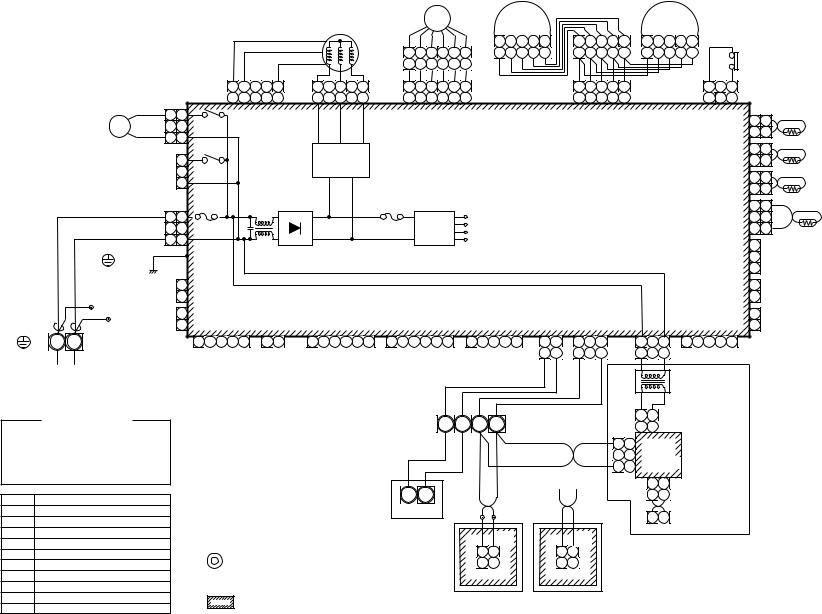
Symbol |
|
Parts name |
|
|
|
|
|
|
|
|
|
|
|
|
|
|
|
|
|
|
|
|
|
|
|
|
||||
FM |
Fan motor |
|
|
|
|
|
|
|
|
|
|
Outdoor unit |
WHI |
BLK |
|
WHI |
BLK |
|
|
|
|
X Y |
|
|
|
|
||||
TA |
Indoor temp sensor |
|
|
|
|
|
|
|
|
|
|
|
|
|
|
|
|
|
|
|
||||||||||
|
|
|
|
|
|
|
|
|
|
|
|
|
|
|
|
|
|
|
|
|
|
|
|
|
|
|
|
|||
TC1 |
Temp sensor |
|
|
|
|
|
|
|
|
|
|
|
|
|
CN1 |
|
|
|
CN001 |
|
|
|
|
|
|
|
|
|
|
|
TCJ |
Temp sensor |
|
|
|
|
|
|
|
|
|
|
|
|
|
(WHI) |
|
|
|
(WHI) |
|
|
|
|
|
|
|
|
|
|
|
TC2 |
Temp sensor |
|
|
1. |
indicates the terminal block, letter at inside |
|
|
1 |
2 |
|
|
1 |
2 |
|
|
|
|
|
|
|
|
|
|
|
||||||
LM1, LM2 Lover motor |
|
|
|
|
1 |
2 |
|
|
1 |
2 |
|
|
|
|
|
|
|
|
|
|
|
|||||||||
DM |
Drain pump motor |
|
|
indicates the terminal number. |
|
|
|
|
|
|
|
|
|
|
|
|
|
|
|
|
|
|
|
|
|
|
||||
FS |
Float switch |
|
|
2. |
A dotted line and broken line indicate the wiring at site. |
|
|
|
|
|
|
|
|
|
|
|
|
|
|
|
|
|
|
|||||||
RY302 |
Drain control relay |
|
3. |
|
indicates the control P.C. board. |
|
|
|
Wired remote |
|
Adaptor for wireless |
|
|
|
|
|
|
|
|
|
||||||||||
PMV |
Pulse Motor Valve |
|
|
|
|
|
controller |
|
remote controller |
|
|
|
|
|
|
|
|
|
||||||||||||
|
|
|
|
|
|
|
|
|
|
|
|
|
|
|
|
|
|
|
|
|||||||||||
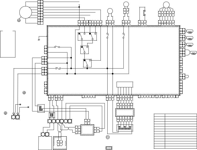
AP0481H, AP0361H, AP0301H, AP0271H,-MMU |
AP0181H, AP0151H, AP0121H, AP0091H,-MMU Model: |
Type Cassette Discharge Air way-4 .1-1-2 |
Unit Indoor .1-2 |
AP0561H |
AP0241H, |
|
|
DIAGRAM WIRING .2
14
FM
Color indication
RED : RED WHI : WHITE YEL : YELLOW BLU : BLUE BLK : BLACK GRY : GRAY PNK : PINK ORN : ORANGE BRW : BROWN GRN : GREEN
Flow selector unit earth screw
Closed end connector
Indoor unit
Earth screw R(L) S(N)
Power supply Single phase 220-240V 50Hz
220V 60Hz
1 1 WHI
22
33 RED
44
55
66
77
9 
 RC
RC
|
|
BLK |
|
|
RED |
|
|
|
|
FAN |
9 |
8 |
7 |
6 |
CN083(WHI) |
9 |
8 |
7 |
6 |
ORN |
|
BLU |
YEL |
|
5 4 3 2 1
5 4 3 2 1
|
LM |
||
DM |
1 |
2 |
|
1 |
2 |
||
|
|||
1 |
2 |
3 |
DP |
1 |
2 |
3 |
LM |
(BLU) |
(GRN) |
||||||
1 |
2 |
3 |
CN068 |
1 |
2 |
3 |
CN033 |
|
|
|
|
|
|
PMV |
|
|
|
|
|
|
|
FS |
6 |
4 |
3 |
1 |
2 |
5 |
|
|
|
|
|
6 |
4 |
3 |
1 |
2 |
5 |
|
1 |
2 |
3 |
FS |
1 |
2 |
3 |
4 |
5 |
6 |
PMV |
(RED) |
(BLU) |
|||||||||
1 |
2 |
3 |
CN030 |
1 |
2 |
3 |
4 |
5 |
6 |
CN082 |
|
|
|
|
|
H |
M |
L |
UL |
|
|
|
CN104 |
1 |
1 |
|
|
|
|
|
|
RY007 |
|
|
|
|
|
|
|
|||
|
|
|
|
|
|
|
|
|
|
|
(YEL) |
2 |
2 |
|
|
|
|
|
|
|
|
|
|
|
|
|
|
TA |
|||
|
|
|
P301 |
|
|
|
|
|
|
|
|
CN102 |
1 |
1 |
|
|
(BLK) |
|
|
|
|
|
|
|
|
|
|||||
|
|
|
|
|
|
RY002 |
RY001 |
|
|
(RED) |
2 |
2 |
|
||
|
|
|
|
|
|
|
|
|
|
TCJ |
|||||
|
|
|
|
|
|
|
|
|
|
|
|
|
|||
|
|
|
|
|
|
|
|
|
|
|
|
|
1 |
1 |
|
|
|
|
|
|
|
RY006 |
|
|
|
|
CN101 |
|
|||
|
|
|
|
|
|
|
|
|
|
(BLK) |
2 |
2 |
|
||
|
|
1 |
|
|
|
|
|
|
|
|
|
TC2 |
|||
CN304 |
RY004 |
|
|
|
|
|
|
|
|
|
|
||||
2 |
|
|
|
|
|
|
|
|
1 |
1 |
|||||
|
|
|
|
|
|
|
|
|
|||||||
(GRY) |
3 |
|
|
|
|
|
|
|
|
|
CN100 |
2 |
2 |
|
|
|
|
|
|
|
|
|
|
|
|
|
(BRW) |
|
|||
|
|
|
|
|
|
|
|
|
Indoor control P.C. board |
3 |
3 |
|
|||
|
|
|
|
|
|
|
|
|
|
TC1 |
|||||
|
1 |
1 |
|
|
|
|
|
|
|
|
|
||||
CN039 |
|
|
|
|
|
|
|
|
|
|
1 |
|
|
||
2 |
2 |
|
|
|
|
|
|
|
|
|
CN080 |
|
|
||
(YEL) |
|
|
|
|
RY005 |
|
|
|
|
2 |
PNL |
|
|||
3 |
3 |
|
Fuse |
|
|
|
|
|
|
(GRN) |
|
||||
|
|
|
|
|
|
|
|
|
3 |
|
|
||||
|
|
|
|
|
|
|
|
|
|
|
|
|
|
||
|
1 |
1 |
|
T5.0A |
|
|
|
|
|
|
|
|
1 |
|
|
|
CN067 250V~ |
|
|
|
|
|
|
|
CN073 |
EXCT |
|||||
|
2 |
2 |
|
|
|
|
|
|
|
(RED) |
2 |
|
|
||
|
3 |
3 |
(BLK) |
|
|
|
|
|
|
|
|
|
|
|
|
|
|
|
|
|
|
|
|
|
|
CN070 |
1 |
1 |
|
||
|
|
|
|
|
|
|
|
|
|
|
|
Filter |
|||
|
|
|
|
|
|
|
|
|
|
|
|
(WHI) |
2 |
2 |
|
|
|
|
|
|
|
|
|
|
|
|
|
|
|||
CN066 |
1 |
|
|
|
|
|
|
Power supply |
|
|
|
1 |
|
|
|
|
|
|
|
|
|
|
|
CN081 |
2 |
|
|
||||
(WHI) |
2 |
|
|
|
|
|
|
circuit |
|
|
|
|
|||
|
|
|
|
|
|
|
|
3 |
|
|
|||||
|
|
|
|
|
|
|
|
|
|
|
|
(BLK) |
|
|
|
CN044 1 |
CN040 |
CN041 |
CN050 |
|
CN074 |
CN075 |
CN061 |
CN032 |
CN060 |
4 |
|
|
|||
(BRW) |
2 |
(BLU) |
(BLU) |
(WHI) |
|
(WHI) |
(WHI) |
(YEL) |
(WHI) |
(WHI) |
5 |
|
|
||
|
|
1 |
2 |
1 |
2 |
3 |
|
|
1 |
2 |
3 |
4 |
5 |
|
|
1 |
2 |
3 |
1 |
2 |
3 |
4 |
5 |
6 |
1 |
2 |
3 |
4 |
5 |
6 |
1 |
2 |
1 |
2 |
3 |
4 |
5 |
6 |
|
|
1 |
2 |
1 |
2 |
3 |
|
|
|
|
|
|
|
|
|
1 |
2 |
3 |
1 |
2 |
3 |
4 |
5 |
6 |
|
|
|
|
|
|
Fan drive |
|
Option |
|
|
|||
TR |
BLU |
BLU |
BLK |
|
BLK |
|
|
|
|
|
|
|
|
|
|
|
|
1 |
2 |
3 |
4 |
5 |
6 |
CN02 |
|
|
|
|
|
|
|
|
|
|
|
|
|
|
|
|
|
|
|
|
|
|
|
|
|
|
|
|
|
|
|
|
|
1 |
2 |
3 |
4 |
5 |
6 |
(YEL) |
|
|
|
|
|
|
|
|
|
|
|
|
|
|
|
|
|
|
|
|
|
|
|
|
|
|
|
|
|
|
|
|
Sub P.C. board |
|
|
|
|
|
|
|
|
|
|
|
|
|
|
|||||
Line Filter |
|
|
|
|
|
|
|
|
|
|
|
|
|
|
|
|
|
|
MCC-1520 |
|
|
|
|
|
|
|
Symbol |
|
|
|
|
|
Parts name |
|||||
|
|
|
|
|
|
|
|
|
|
|
|
|
|
|
|
|
|
|
|
|
|
|
|
|
|
|
|
|
|
|
|
|
|
|||||
|
|
|
|
|
|
|
|
|
|
|
|
|
|
|
|
|
1 |
2 |
3 |
4 |
5 |
6 |
|
|
|
|
|
|
|
FM |
|
Fan motor |
|
|
||||
|
|
|
|
|
|
|
|
|
|
|
|
Network |
|
|
|
|
CN01 |
|
|
|
|
|
|
|
|
|
||||||||||||
|
|
|
|
A B X Y |
|
CN01 1 |
2 |
|
|
|
|
1 |
2 |
3 |
4 |
5 |
6 |
(WHI) |
|
|
|
|
|
|
RC |
|
Running capacitor |
|||||||||||
|
U1 |
U2 |
|
adaptor |
|
|
|
|
|
|
|
|
|
|
|
|
||||||||||||||||||||||
|
|
|
|
|
|
|
|
|
|
|
|
|
TR |
|
Transformer |
|
||||||||||||||||||||||
|
|
|
|
|
|
|
|
(WHI) |
1 |
2 |
(Option) |
|
|
|
|
|
|
|
|
|
|
|
|
|
|
|
|
|
|
|
||||||||
|
|
|
|
|
|
|
|
|
|
|
|
|
|
|
|
|
|
|
|
|
|
|
|
|
|
|
|
|
|
|
|
LM |
|
Louver motor |
|
|||
|
|
|
|
|
|
|
3 |
3 |
|
|
|
|
1 |
1 |
|
|
|
|
|
|
|
|
|
|
TR |
|
|
|
|
|
|
TA |
|
Indoor temp sensor |
||||
|
|
|
|
|
|
|
|
2 |
|
|
|
|
|
|
|
|
|
|
|
|
|
|
|
|
|
|
|
TC1,TC2,TCJ Temp sensor |
|
|||||||||
|
|
|
|
|
|
|
|
|
|
|
|
2 |
2 |
|
|
|
|
|
|
|
|
|
|
|
|
|
|
|
|
|
||||||||
|
|
|
|
|
|
|
1 |
1 |
|
|
|
|
|
|
|
|
|
|
|
|
|
|
|
|
|
|
|
|
RY001 |
|
Louver control relay |
|||||||
U1 |
U2 |
|
|
|
|
|
|
|
|
|
CN03 |
|
|
|
|
|
|
|
|
|
|
|
|
|
|
|
|
|
||||||||||
|
|
|
|
|
CN02 |
|
|
|
|
|
|
|
|
|
|
|
|
|
|
|
|
|
|
|
|
RY002 |
|
Drain control relay |
||||||||||
|
|
|
|
|
MCC-1401 |
(RED) |
1. |
|
indicates the terminal block, letter at inside |
|
|
|
|
|||||||||||||||||||||||||
|
|
|
|
|
|
|
(BLU) |
|
|
|
|
RY004 |
|
Heater control relay |
||||||||||||||||||||||||
|
|
|
|
|
|
CN1 |
|
|
|
|
|
|
|
|||||||||||||||||||||||||
|
|
|
|
|
|
(WHI) |
|
|
|
|
|
|
|
|
|
indicates the terminal number. |
|
|
|
|
|
|
RY005~007 |
Fan motor control relay |
||||||||||||||
Outdoor unit |
|
|
1 |
2 |
|
|
|
|
|
|
|
|
2. |
A dotted line and broken line indicate the wiring at site. |
|
|
FS |
|
Float switch |
|
||||||||||||||||||
|
|
1 |
2 |
|
|
|
|
|
|
|
|
|
|
DM |
|
Drain pump motor |
||||||||||||||||||||||
|
|
|
|
|
|
|
|
|
|
|
|
|
3. |
|
|
indicates the control P.C. board. |
|
|
|
|
|
|
|
|||||||||||||||
|
|
|
Remote controller |
|
|
|
|
|
|
|
|
|
|
|
|
|
|
|
|
PMV |
|
Pulse Motor Valve |
||||||||||||||||
|
|
|
|
|
|
|
|
|
|
|
|
|
|
|
|
|
|
|
|
|
|
|
|
|
|
|
|
|
|
|
|
|
||||||
|
Model: |
.2-1-2 |
AP0301WH, AP0271WH, AP0241WH,-MMU |
AP0121WH, AP0091WH, AP0071WH,-MMU |
Type Cassette Discharge Air way-2 |
AP0481WH |
AP0151WH, |
|
|
AP0181WH, |
|
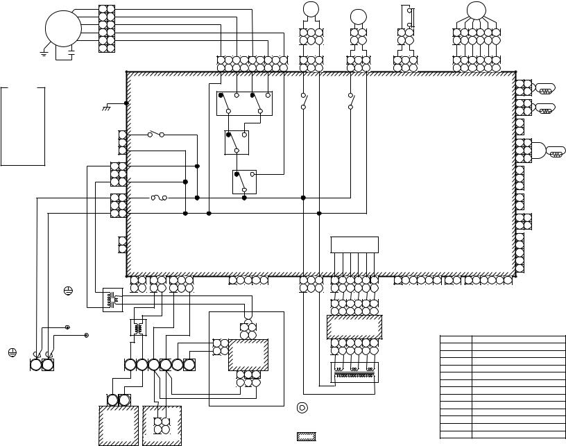
15
|
1 |
1 |
|
|
2 |
2 |
|
FM |
3 |
3 |
|
4 |
4 |
||
|
|||
|
5 |
5 |
|
|
6 |
6 |
|
|
RC |
|
RED |
|
BLK |
|
|
ORN |
|
BLU |
|
YEL |
FAN |
9 |
8 |
7 |
6 |
5 |
4 |
3 |
2 |
1 |
CN083(WHI) |
9 |
8 |
7 |
6 |
5 |
4 |
3 |
2 |
1 |
|
DM |
|
|
|
|
|
|
LM |
|
1 |
2 |
3 |
2 |
1 |
1 |
2 |
3 |
2 |
1 |
1 |
2 |
3 |
DP |
1 |
2 |
3 |
LM |
(BLU) |
(GRN) |
||||||
1 |
2 |
3 |
CN068 |
1 |
2 |
3 |
CN033 |
|
|
FS |
|
|
PMV |
|
|
|
||
|
|
|
|
|
|
|
|
|
||
2 |
|
1 |
|
6 |
4 |
3 |
1 |
2 |
5 |
|
2 |
|
1 |
|
6 |
4 |
3 |
1 |
2 |
5 |
|
1 |
2 |
3 |
FS |
1 |
2 |
3 |
4 |
5 |
6 |
PMV |
(RED) |
(BLU) |
|||||||||
1 |
2 |
3 |
CN030 |
1 |
2 |
3 |
4 |
5 |
6 |
CN082 |
|
Color |
|
|
|
|
H |
M |
L |
UL |
|
CN104 |
1 |
1 |
|
|
|
|
|
|
RY007 |
|
|
|
|
|
||||
indication |
CN301 |
|
|
|
|
(YEL) |
2 |
2 |
|
|||||
|
|
|
|
|
TA |
|||||||||
RED : RED |
|
(BLK) |
|
|
|
|
|
CN102 |
1 |
1 |
||||
WHI |
: WHITE |
|
|
|
|
|
|
|
|
|
|
|||
|
|
|
|
|
|
|
|
|
(RED) |
2 |
2 |
|
||
YEL |
: YELLOW |
|
|
|
|
|
|
|
RY002 |
RY001 |
TCJ |
|||
|
|
|
|
|
|
|
|
|
|
|||||
BLU |
: BLUE |
|
|
|
|
|
|
|
|
|
CN101 |
1 |
|
|
BLK |
: BLACK |
Heater |
|
RY006 |
|
|
|
|
||||||
|
|
|
2 |
|
|
|||||||||
GRY : GRAY |
|
|
|
1 |
|
|
|
|
|
(BLK) |
|
|
||
PNK : PINK |
CN304 |
RY004 |
|
|
|
|
|
|
|
|
||||
2 |
|
|
|
|
|
1 |
1 |
|
||||||
ORN : ORANGE |
(GRY) |
3 |
|
|
|
|
|
CN100 |
2 |
2 |
|
|||
BRW : BROWN |
|
|
|
|
|
|
|
|
|
|||||
|
|
|
|
|
|
|
|
(BRW) |
|
|||||
|
|
|
|
|
|
|
|
|
3 |
3 |
|
|||
GRN : GREEN |
|
|
|
|
|
|
|
|
|
Indoor control P.C. board |
TC1 |
|||
|
|
|
|
1 |
1 |
|
|
|
|
|
|
|
||
|
|
CN309 |
|
|
|
|
|
|
1 |
|
|
|||
|
|
2 |
2 |
|
|
|
|
|
CN080 |
|
|
|||
|
|
(YEL) |
|
|
|
RY005 |
|
|
2 PNL |
|
||||
|
|
|
|
3 |
3 |
|
|
|
|
|
(GRN) |
3 |
|
|
|
|
|
|
|
|
|
|
|
|
|
|
|
|
|
AC IN 1 |
1 |
CN067 |
Fuse |
|
|
|
|
|
|
|
|
|
|
|
|
|
|
|
|
|
|
|
|
|
|
|
|
|
|
|
|
CN073 |
1 |
EXCT |
|||||
2 |
2 |
|
|
|
|
|
|
|
|
|
|
|
|
|
|
|
|
|
|
|
|
|
|
|
|
|
|
|
|
|
(RED) |
2 |
|
|
|||||
3 |
3 |
(BLK) |
T5.0A |
|
|
|
|
|
|
|
|
|
|
|
|
|
|
|
|
|
|
|
|
|
|
|
|
|
|
|
|
|
|
|
|
|
|
||
|
|
|
|
|
|
|
|
|
|
|
|
|
|
|
|
|
|
|
|
|
|
|
|
|
|
|
|
|
|
|
|
CN070 |
1 |
1 |
|
||||
|
|
|
|
|
|
|
|
|
|
|
|
|
|
|
|
|
|
|
|
|
|
|
|
|
|
|
|
|
|
|
|
|
|
Filter |
|||||
|
|
|
|
|
|
|
|
|
|
|
|
|
|
|
|
|
|
|
|
|
|
|
|
|
|
|
|
|
|
|
|
|
|
|
(WHI) |
2 |
2 |
||
CN066 |
1 |
|
|
|
|
|
|
|
|
|
|
|
|
|
|
|
|
Power supply |
|
|
|
|
|
|
|
|
|
|
|
|
|
|
|
1 |
|
|
|||
|
|
|
|
|
|
|
|
|
|
|
|
|
|
|
|
|
|
|
|
|
|
|
|
|
|
|
|
CN081 |
2 |
|
|
||||||||
(WHI) |
2 |
|
|
|
|
|
|
|
|
|
|
|
|
|
|
|
|
|
circuit |
|
|
|
|
|
|
|
|
|
|
|
|
|
|
|
|||||
|
|
|
|
|
|
|
|
|
|
|
|
|
|
|
|
|
|
|
|
|
|
|
|
|
|
|
|
|
|
3 |
|
|
|||||||
|
|
|
|
|
|
|
|
|
|
|
|
|
|
|
|
|
|
|
|
|
|
|
|
|
|
|
|
|
|
|
|
|
|
|
(BLK) |
|
|
||
|
|
CN044 CN040 |
CN041 |
|
CN050 |
|
CN074 |
|
|
|
|
|
|
|
|
CN075 |
|
CN061 |
|
|
CN032 |
|
|
CN060 |
|
4 |
|
|
|||||||||||
|
|
(BRW) (BLU) |
(BLU) |
|
(WHI) |
|
(WHI) |
|
|
|
|
|
|
|
|
(WHI) |
|
(YEL) |
|
|
(WHI) |
|
|
(WHI) |
|
5 |
|
|
|||||||||||
TR |
|
1 |
2 |
1 |
2 |
1 |
2 |
3 |
1 |
2 |
3 |
4 |
5 |
1 |
2 |
3 |
1 |
2 |
3 |
4 |
5 |
6 |
1 |
2 |
3 |
4 |
5 |
6 |
1 |
2 |
1 |
2 |
3 |
4 |
5 |
6 |
|
|
|
|
1 |
2 |
1 |
2 |
1 |
|
3 |
|
|
|
|
|
1 |
2 |
3 |
1 |
2 |
3 |
4 |
5 |
6 |
|
|
|
|
|
|
Fan drive |
|
Option |
|
|
|
|
|||||
|
|
|
|
|
|
|
|
|
|
|
|
|
|
|
|
|
|
|
|||||||||||||||||||||
RED |
WHI |
Flow selector |
|
|
BLU |
|
|
|
|
|
|
|
1 |
2 |
3 |
4 |
5 |
6 |
(YEL) |
|
|
||
screw |
|
|
|
|
|
|
|
|
|
|
|
||||||||||||
|
|
unit earth |
|
|
|
|
|
|
|
|
|
|
|
1 |
2 |
3 |
4 |
5 |
6 |
CN02 |
|
|
|
|
|
RED |
Closed end |
|
|
|
BLU |
|
MCC-1401 |
|
|
Network |
Sub P.C. board |
|
|
|
|||||||
|
|
Line Filter |
|
|
|
|
CN01 1 |
|
2 |
|
|
|
|||||||||||
|
|
|
connector |
|
|
|
|
|
adaptor |
|
MCC-1520 |
|
|
|
|
||||||||
|
|
|
|
|
|
|
|
|
|
|
|
|
|
|
|||||||||
|
|
|
WHI |
|
|
|
|
|
|
(WHI) 1 |
|
2 |
(Option) |
|
|
|
|
|
|
|
Symbol |
Parts name |
|
|
|
|
|
|
|
|
|
1 |
1 |
|
|
|
|
1 |
2 |
3 |
4 |
5 |
6 |
CN01 |
|||
|
|
|
|
|
BLU |
BLU |
BLK |
BLK |
Network |
|
FM |
Fan motor |
|||||||||||
|
|
|
|
|
2 |
2 |
|
1 |
2 |
3 |
4 |
5 |
6 |
(WHI) |
RC |
Running capacitor |
|||||||
Indoor unit |
|
|
BLU |
|
|
|
|
|
CN03 |
adaptor |
|
|
|
|
|
|
|
|
|
Power transformer |
|||
|
|
|
|
|
A B X Y |
P.C. board |
|
|
|
|
|
|
|
TR |
|||||||||
Earth screw R(L) |
S(N) |
|
|
U1 |
U2 |
(RED) |
|
|
|
|
|
|
|
||||||||||
|
|
3 |
2 |
1 |
|
|
|
|
|
|
|
TR |
LM |
Louver motor |
|||||||||
Power supply |
|
|
|
|
|
AI-NET |
|
|
CN02 |
|
|
|
|
|
|
TA |
Indoor temp sensor |
||||||
|
|
|
|
|
central control |
|
|
|
|
|
|
|
|
|
|||||||||
Single phase |
|
|
|
|
|
terminal |
|
|
3 |
2 |
1 |
(BLU) |
|
|
|
|
|
|
|
TC1,TCJ |
Temp sensor |
||
220-240V 50Hz |
|
|
|
|
|
|
|
|
|
|
|
|
|
|
|
|
|
|
|
RY001 |
Flap motor control relay |
||
220V 60Hz |
|
|
|
|
|
|
|
|
|
|
|
|
|
|
|
|
|
|
|
||||
|
|
|
|
|
|
|
|
|
|
|
|
|
|
|
|
|
|
|
RY002 |
Drain pump control relay |
|||
|
|
|
|
U1 |
U2 |
|
|
|
|
|
|
|
|
|
|
|
|
|
|
|
|
||
|
|
|
|
|
|
|
|
|
|
|
|
|
|
|
|
|
|
|
|
RY004 |
Heater control relay |
||
|
|
|
|
|
|
|
|
|
|
|
|
|
|
1. |
indicates the terminal block, letter at inside |
||||||||
|
|
|
|
|
|
|
|
CN1 |
|
|
|
|
|
RY005~007 |
Fan motor control relay |
||||||||
|
|
|
|
|
|
|
|
|
|
|
|
|
|
|
|
|
|
|
|
|
|||
|
|
|
|
|
|
|
|
(WHI) |
|
|
|
|
|
|
indicates the terminal number. |
|
|
FS |
Float switch |
||||
|
|
|
|
Outdoor |
|
1 |
2 |
|
|
|
|
|
|
|
|
||||||||
|
|
|
|
|
|
|
|
|
|
|
|
|
|
|
|
|
|
||||||
|
|
|
|
|
|
|
|
|
|
2. |
A dotted line and broken line indicate the wiring at site. |
DM |
Drain pump motor |
||||||||||
|
|
|
|
unit |
|
1 |
2 |
|
|
|
|
|
|||||||||||
|
|
|
|
|
|
|
|
|
|
3. |
indicates the control P.C. board. |
PMV |
Pulse Motor Valve |
||||||||||
|
|
|
|
|
|
Remote controller |
|
|
|
|
|
||||||||||||
|
|
|
|
|
|
|
|
|
|
|
|
|
|||||||||||
Model: |
.3-1-2 |
AP0121YH AP0091YH, AP0071YH,-MMU |
Type Cassette Discharge Air way-1 |
|
type) (Compact |
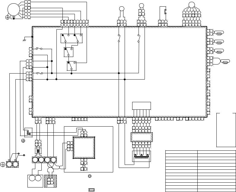
16
|
|
1 |
1 |
|
|
|
|
|
|
|
|
|
|
|
|
|
|
|
|
|
|
|
|
|
|
|
|
|
|
|
|
|
|
|
|
|
|
|
|
|
|
|
|
2 |
|
|
|
|
|
|
|
|
|
|
|
|
|
|
|
|
|
|
|
|
LM |
|
|
|
|
|
|
|
|
PMV |
|
|
|
|
|
|
|
||
|
FM |
3 |
3 |
|
|
|
|
|
|
|
|
|
|
|
|
|
|
|
|
DM |
|
|
|
|
|
|
|
|
|
|
|
|
|
|
|
|
|
|
|
|
|
|
4 |
4 |
|
|
|
|
|
|
|
|
|
|
|
|
|
|
|
|
|
|
1 |
2 |
|
|
|
|
|
|
|
|
|
|
|
|
|
|
|
|
|
||
|
|
|
|
|
|
|
|
|
|
|
|
|
|
|
|
|
|
|
|
|
|
|
|
FS |
|
|
|
|
|
|
|
|
|
|
|
||||||
|
|
|
|
|
|
|
|
|
|
|
|
|
|
|
|
|
|
|
|
|
|
|
|
|
6 |
4 |
3 |
1 |
2 |
5 |
|
|
|
|
|
||||||
|
|
5 |
5 |
|
|
|
|
|
|
|
|
|
|
|
|
|
|
|
|
|
|
|
1 |
2 |
|
|
|
|
|
|
|
|
|
|
|
||||||
|
|
|
|
|
|
|
|
|
|
|
|
|
|
|
|
|
|
|
|
|
|
|
|
|
|
|
6 |
4 |
3 |
1 |
2 |
5 |
|
|
|
|
|
||||
|
RC |
6 6 |
|
|
|
|
|
|
|
|
|
|
|
|
|
|
|
|
|
DM |
|
|
|
LM |
|
|
FS |
PMV |
|
|
|
|
|||||||||
|
|
|
|
|
|
|
FAN |
RED BLK ORN BLU YEL |
|
|
|
|
|
|
|
|
|
|
|
|
|
|
|
|
|
|
|||||||||||||||
|
|
|
|
|
|
|
|
|
|
|
|
|
|
|
|
|
|
|
|
|
|
|
|
|
|
|
|
||||||||||||||
|
|
|
|
|
|
|
|
|
|
|
1 |
3 |
|
|
1 |
3 |
|
|
|
1 |
3 |
|
1 |
2 |
3 |
4 |
5 |
6 |
|
|
|
|
|
||||||||
|
|
|
|
|
|
|
|
|
CN083 9 |
7 |
5 |
3 |
1 |
|
CN068 |
|
|
|
CN033 |
CN030 |
CN082 |
|
|
|
|||||||||||||||||
|
|
|
|
|
|
|
|
|
(WHI) |
9 |
7 |
5 |
3 |
1 |
|
(BLU) |
1 |
3 |
|
|
1 |
3 |
|
(GRN) |
1 |
3 |
(RED) |
1 |
2 |
3 |
4 |
5 |
6 |
(BLU) |
|
|
|
||||
|
|
|
|
|
|
|
|
|
|
|
|
H |
|
M |
L |
UL |
|
|
|
|
|
|
|
|
|
|
|
|
|
|
|
|
|
|
CN104 |
1 |
1 |
TA |
|
||
|
|
|
|
|
|
|
|
|
|
|
RY007 |
|
|
|
|
|
|
|
|
|
|
|
|
|
|
|
|
|
|
|
|
|
|
|
|
|
|
||||
|
|
|
|
|
|
|
|
|
|
|
|
|
|
|
|
|
|
|
|
|
|
|
|
|
|
|
|
|
|
|
|
|
|
|
(YEL) |
2 |
2 |
|
|
||
|
|
P301 |
|
|
|
|
|
|
|
|
|
|
|
|
|
|
|
|
|
|
|
|
|
|
|
|
|
|
|
|
|
|
|
|
|
|
|||||
|
|
|
|
|
|
|
|
|
|
|
|
|
|
|
|
|
|
|
|
|
|
|
|
|
|
|
|
|
|
|
|
|
|
|
|
|
|
|
|
||
|
|
BLK |
|
|
|
|
|
|
|
|
|
|
|
|
|
|
RY002 |
|
|
RY001 |
|
|
|
|
|
|
|
|
|
|
|
|
|
CN102 |
1 |
1 |
TCJ |
|
|||
|
|
|
|
|
|
|
|
|
|
|
|
|
|
|
|
|
|
|
|
|
|
|
|
|
|
|
|
|
|
|
|
|
|
|
|
|
|
||||
|
|
|
|
|
|
|
|
|
|
|
|
|
|
|
|
|
|
|
|
|
|
|
|
|
|
|
|
|
|
|
|
|
|
|
|
(RED) |
2 |
2 |
|
|
|
|
|
|
1 |
|
|
RY004 |
|
|
|
|
|
RY006 |
|
|
|
|
|
|
|
|
|
|
|
|
|
|
|
|
|
|
|
|
|
|
1 |
1 |
TC2 |
|
|||
|
|
|
|
|
|
|
|
|
|
|
|
|
|
|
|
|
|
|
|
|
|
|
|
|
|
|
|
|
|
|
|
CN101 |
|
||||||||
|
|
|
|
|
|
|
|
|
|
|
|
|
|
|
|
|
|
|
|
|
|
|
|
|
|
|
|
|
|
|
|
|
|
||||||||
|
|
|
|
|
(GRY) |
|
|
|
|
|
|
|
|
|
|
|
|
|
|
|
|
|
|
|
|
|
|
|
|
|
|
|
|
|
(BLK) |
2 |
2 |
|
|
||
|
|
|
3 |
|
|
|
|
|
|
|
|
|
|
|
|
|
|
|
|
|
|
|
|
|
|
|
|
|
|
|
|
|
|
|
|
|
|
|
|
||
|
|
|
|
CN304 |
|
|
|
|
|
|
|
|
|
|
|
|
|
|
|
|
|
|
|
|
|
|
|
|
|
|
|
|
|
|
|
|
|
|
|
||
|
|
|
|
|
|
|
|
|
|
|
|
|
|
|
|
|
|
|
|
|
|
|
|
|
|
|
|
|
|
|
|
|
|
|
|
1 |
1 |
|
TC1 |
||
|
|
|
|
|
|
|
|
|
|
|
|
|
|
RY005 |
|
|
|
|
|
|
|
|
|
|
|
Control P.C. board |
|
|
|
|
CN100 |
|
|||||||||
|
|
1 |
1 |
|
|
|
|
|
|
|
|
|
|
|
|
|
|
|
|
|
|
|
|
|
|
|
|
|
2 |
|
|
|
|||||||||
|
|
|
|
|
|
|
|
|
|
|
|
|
|
|
|
|
|
|
|
|
|
|
|
|
|
|
(BRW) |
|
|
|
|||||||||||
|
|
3 |
3 |
|
(YEL) |
|
|
|
|
|
|
|
|
|
|
|
|
|
|
|
|
|
|
|
|
for Indoor unit |
|
|
|
|
|
|
|
3 |
3 |
|
|
||||
|
|
|
CN309 |
|
|
|
|
|
|
|
|
|
|
|
|
|
|
|
|
|
|
|
|
|
MCC-1403 |
|
|
|
|
|
|
|
|
|
|
|
|||||
|
|
AC IN |
|
|
|
|
|
|
|
|
|
|
|
|
|
|
|
|
|
|
|
|
|
|
|
|
|
|
|
|
|
1 |
|
|
|
||||||
|
|
|
|
|
|
|
|
|
|
|
|
|
|
|
|
|
|
|
|
|
|
|
|
|
|
|
|
|
|
|
|
|
|
CN080 |
|
|
|
||||
|
|
1 |
1 |
|
|
|
|
|
|
|
|
|
|
|
|
|
|
|
|
|
|
|
|
|
|
|
|
|
|
|
|
|
|
|
|
2 |
PNL |
|
|
||
|
|
|
FUSE |
|
|
|
|
|
|
|
|
|
|
|
|
|
|
|
|
|
|
|
|
|
|
|
|
|
|
|
|
|
(GRN) |
|
|
||||||
|
|
|
|
|
|
|
|
|
|
|
|
|
|
|
|
|
|
|
|
|
|
|
|
|
|
|
|
|
|
|
|
|
|
3 |
|
|
|
||||
|
|
|
|
|
|
|
|
|
|
|
|
|
|
|
|
|
|
|
|
|
|
|
|
|
|
|
|
|
|
|
|
|
|
|
|
|
|
|
|||
|
|
3 |
3 |
T5.0A 250V~ |
|
|
|
|
|
|
|
|
|
|
|
|
|
|
|
|
|
|
|
|
|
|
|
|
|
|
|
|
|
|
|
|
|
|
|||
|
|
|
(BLK) |
|
|
|
|
|
|
|
|
|
|
|
|
|
|
|
|
|
|
|
|
|
|
|
|
|
|
|
|
|
|
|
|
|
|
|
|||
|
|
|
|
|
|
|
|
|
|
|
|
|
|
|
|
|
|
|
|
|
|
|
|
|
|
|
|
|
|
|
|
|
|
CN073 |
1 |
|
|
|
|||
|
|
|
|
|
CN067 |
|
|
|
|
|
|
|
|
|
|
|
|
|
|
|
|
|
|
|
|
|
|
|
|
|
|
|
|
|
EXCT |
|
|||||
|
|
|
|
|
|
|
|
|
|
|
|
|
|
|
|
|
|
|
|
|
|
|
|
|
|
|
|
|
|
|
|
|
|
(RED) |
2 |
|
|||||
|
|
|
|
|
|
|
|
|
|
|
|
|
|
|
|
|
|
|
|
|
|
|
|
|
|
|
|
|
|
|
|
|
|
|
|
|
|
|
|||
|
|
CN066 |
|
|
|
|
|
|
|
|
|
|
|
|
|
|
|
|
|
|
|
|
|
|
|
|
|
|
|
|
|
|
|
|
CN070 |
1 |
FILTER |
|
|||
|
|
(WHI) |
|
|
|
|
|
|
|
|
|
|
|
|
|
|
|
|
|
|
|
|
|
|
|
|
|
|
|
|
|
|
|
|
(WHI) |
2 |
|
||||
|
|
|
|
|
|
|
|
|
|
|
|
|
|
|
|
|
|
|
|
|
|
|
|
|
|
|
|
|
|
|
|
|
|
|
|
|
|||||
|
|
|
1 |
|
|
|
|
|
|
|
|
|
|
|
|
|
|
|
|
|
|
|
|
|
|
|
|
|
|
|
|
|
|
|
|
|
|
|
|
|
|
|
|
|
2 |
|
|
|
|
|
|
|
|
|
|
|
|
|
|
|
|
|
|
|
|
|
|
|
|
|
|
|
|
|
|
|
|
|
|
1 |
|
|
|
|
|
CN044 |
|
|
|
|
|
|
|
|
|
|
|
|
|
|
|
|
|
Power supply |
|
|
|
|
|
|
|
|
|
CN081 |
2 |
|
|
|
|||||||
|
|
(BRW) |
|
|
|
|
|
|
|
|
|
|
|
|
|
|
|
|
|
|
|
|
|
|
|
|
|
|
3 |
|
|
|
|||||||||
|
|
|
|
|
|
|
|
|
|
|
|
|
|
|
|
|
|
|
|
|
circuit |
|
|
|
|
|
|
|
|
|
|
|
(BLK) |
|
|
|
|||||
|
|
|
1 |
|
CN040 |
CN041 |
|
|
|
|
CN050 |
|
|
|
|
|
|
|
|
|
|
CN075 |
|
CN061 |
CN032 |
|
CN060 |
|
4 |
|
|
Color |
|||||||||
|
|
|
2 |
|
|
|
|
|
|
|
|
|
|
|
|
|
|
|
|
|
|
5 |
|
|
|||||||||||||||||
|
|
|
|
(BLU) |
|
|
|
|
|
|
|
|
|
|
|
|
|
|
|
(YEL) |
|
(WHI) |
|
|
(WHI) |
|
|
|
|||||||||||||
|
|
|
|
|
(BLU) |
|
|
|
|
(WHI) |
|
|
|
|
|
|
|
|
|
|
|
(WHI) |
|
|
|
|
|
|
|
indication |
|||||||||||
|
|
|
|
|
|
|
|
|
|
|
|
|
|
|
|
|
|
|
|
|
|
|
|
|
|
|
|
|
|
|
|
|
|
||||||||
|
|
EMG |
1 |
2 |
1 |
2 |
3 |
RC |
|
|
1 |
2 |
3 4 |
5 |
|
CN074 |
1 |
3 |
1 |
2 |
3 |
4 |
5 |
6 |
1 |
2 |
3 4 |
5 6 |
1 2 |
1 |
2 3 4 5 6 |
|
|
RED : RED |
|||||||
|
|
1 |
2 |
1 |
|
3 |
|
|
|
|
|
|
|
|
(WHI) |
1 |
3 |
1 |
2 |
3 |
4 |
5 |
6 |
|
|
|
|
FAN |
|
OPTION |
|
|
|
WHI |
: WHITE |
||||||
|
|
|
|
|
BLU |
BLU |
BLK |
|
BLK |
|
|
|
|
|
|
|
|
|
|
|
|
|
|
|
|
|
|
|
|
DRIVE |
|
|
|
|
|
|
|
|
YEL |
: YELLOW |
|
|
|
|
|
|
|
|
|
|
|
|
|
|
|
|
|
|
|
|
|
|
|
|
|
|
|
|
|
|
|
|
|
|
|
BLU |
: BLUE |
||||||
|
|
|
|
|
|
|
|
|
|
|
|
|
|
|
|
|
1 |
2 |
3 4 5 6 CN02 |
|
|
|
|
|
|
|
|
|
|
|
|
||||||||||
|
|
|
|
|
|
|
|
|
|
|
|
|
|
|
1 |
2 |
Network Adapter |
|
|
1 |
2 |
3 |
4 |
5 |
6 |
(YEL) |
|
|
|
|
|
|
|
|
|
|
|
|
BLK |
: BLACK |
|
|
|
|
|
|
|
|
|
|
|
|
|
|
|
|
|
(Option) |
|
|
|
|
|
|
|
|
|
|
|
|
|
|
|
|
|
|
|
|
|
GRY : GRAY |
|||
|
|
|
|
|
|
|
|
|
|
|
|
|
|
|
1 |
2 |
|
|
|
Sub P.C. board |
|
|
|
|
|
|
|
|
|
|
|
|
|
PNK : PINK |
|||||||
|
|
|
|
|
|
|
|
|
|
|
|
|
|
|
|
|
|
|
|
|
|
|
|
|
|
|
|
|
|
|
|
||||||||||
|
|
TR |
|
|
|
|
|
|
|
|
|
|
|
CN01(WHI) |
|
|
|
|
MCC-1520 |
|
|
|
|
|
|
|
|
|
|
|
|
|
|
ORN : ORANGE |
|||||||
|
|
|
|
|
1 |
2 |
|
|
|
|
|
|
|
|
|
|
|
|
|
|
|
|
|
|
|
|
|
|
|
|
|
|
|
|
|
|
BRW : BROWN |
||||
|
Flow selector |
|
|
|
|
|
|
3 |
3 |
|
|
|
|
|
|
|
1 |
2 |
3 |
4 |
5 |
6 |
CN01 |
|
|
|
|
|
|
|
|
|
|
|
|
||||||
|
|
1 |
2 |
|
|
|
|
|
CN02 |
|
|
|
|
|
|
|
|
|
|
|
|
|
|
|
|
|
GRN : GREEN |
||||||||||||||
|
|
|
|
|
|
|
|
2 |
|
|
|
|
|
|
|
|
|
|
|
|
|
|
|
|
|
||||||||||||||||
|
unit earth |
|
|
|
|
|
|
|
|
|
|
|
|
|
|
|
1 |
2 |
3 |
4 |
5 |
6 |
(WHI) |
|
|
|
|
|
|
|
|
|
|
|
|
|
|
||||
|
|
screw |
|
|
|
|
|
|
|
|
|
1 |
1 |
(BLU) |
|
|
|
|
|
|
|
|
|
|
|
|
|
|
|
|
|
|
|
|
|
|
Parts name |
||||
|
|
Line Filter |
|
|
|
|
|
|
|
|
|
|
|
|
|
|
|
|
|
|
|
|
|
|
|
|
|
Symbol |
|
|
|
|
|
|
|||||||
Indoor unit |
|
|
|
|
|
|
|
|
|
|
|
|
|
|
CN03(RED) |
|
|
|
|
|
|
|
|
|
TR |
|
FM |
|
|
|
|
|
Fan motor |
|
|
|
|||||
Closed-end |
|
|
|
|
|
|
|
|
|
|
|
|
|
|
|
|
|
|
|
|
|
|
|
|
RC |
|
|
|
|
|
Running capacitor |
|
|||||||||
earth screw |
U1 |
U2 |
A |
|
B |
|
|
|
|
1 |
2 |
|
|
|
|
|
|
|
|
|
|
|
|
|
|
|
|
|
|
||||||||||||
connector |
|
|
|
|
|
|
|
|
|
|
|
|
|
|
|
|
|
TR |
|
|
|
|
|
Transformer |
|
|
|||||||||||||||
|
|
|
|
|
|
|
|
|
|
|
|
|
|
|
|
|
|
|
|
|
|
|
|
|
|||||||||||||||||
R(L) |
S(N) |
|
|
|
|
|
|
|
|
|
|
|
|
|
1 |
2 |
|
|
|
|
|
|
|
|
|
|
|
|
|
|
|
|
|
|
|
||||||
|
|
|
|
|
|
|
|
|
|
|
|
|
|
|
|
|
|
|
|
|
|
|
|
|
LM |
|
|
|
|
|
Lover motor |
|
|
||||||||
|
|
|
|
|
|
|
|
|
|
|
|
|
|
|
|
|
|
|
|
|
|
|
|
|
|
|
|
|
|
|
|
|
|
||||||||
Power supply |
|
|
|
|
|
|
|
|
|
|
|
|
|
X Y |
|
MCC-1401 |
|
|
|
|
|
|
|
|
|
|
TA |
|
|
|
|
|
Indoor temp sensor |
|
|||||||
|
|
|
|
|
|
|
|
|
|
|
|
|
|
|
|
|
|
|
|
|
|
|
|
|
TC1,TC2,TCJ |
|
|
|
|
Temp sensor |
|
|
|||||||||
|
|
|
|
|
|
|
|
|
|
|
|
|
|
|
|
|
|
|
|
|
|
|
|
|
|
|
|
|
|
|
|
|
|||||||||
single phase |
|
|
|
|
|
|
|
|
|
|
|
|
|
|
|
|
|
|
|
|
|
|
|
|
|
|
|
|
|
|
|
|
|
||||||||
|
|
|
|
|
|
|
|
|
|
|
|
|
|
|
|
|
|
|
|
|
|
|
|
|
|
|
RY001 |
|
|
|
|
|
Louver control relay |
|
|||||||
220-240V 50Hz |
|
|
|
|
|
|
|
|
|
|
|
|
|
1. |
|
Indicates the terminal bolock, letter. |
|
|
|
|
|
|
|
|
|
|
|||||||||||||||
220V 60Hz |
|
U1 |
U2 |
|
|
|
|
|
|
|
|
|
|
|
|
|
|
RY002 |
|
|
|
|
|
Drain control relay |
|
||||||||||||||||
|
1 |
|
2 |
|
|
|
|
|
|
|
Letter at inside indicates the terminal number. |
|
|
|
|
|
|
|
|||||||||||||||||||||||
|
|
|
|
|
|
|
|
|
|
|
|
|
|
|
|
RY005~007 |
|
|
|
|
Fan motor control relay |
||||||||||||||||||||
|
|
|
|
|
|
|
1 |
|
2 |
|
|
|
|
|
|
2. A dotted line and broken line indicate |
|
|
|
|
|
|
|
|
|
||||||||||||||||
|
|
|
Outdoor unit |
|
Remote Controller |
|
|
|
|
|
|
FS |
|
|
|
|
|
Float switch |
|
|
|||||||||||||||||||||
|
|
|
CN1 |
|
|
the wiring at side. |
|
|
|
|
|
|
|
|
|
|
|
|
|
|
|
|
|
||||||||||||||||||
|
|
|
|
|
|
|
|
|
|
|
|
|
|
|
|
|
|
|
|
|
|
|
|
DM |
|
|
|
|
|
Drain pump motor |
|
||||||||||
|
|
|
|
|
|
|
|
|
|
|
|
|
|
|
|
3. |
|
indicate the control p.c. board. |
|
|
|
|
|
|
|
|
|
|
|
||||||||||||
|
|
|
|
|
|
|
|
|
|
|
|
|
|
|
|
|
|
|
|
|
|
PMV |
|
|
|
|
|
Pulse motor valve |
|
||||||||||||
AP0241SH AP0181SH, AP0151SH,-MMU Model:
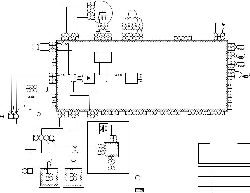
17
|
|
|
|
|
|
5 |
5 |
|
|
FM |
|
|
|
|
|
|
|
|
|
|
|
|
|
|
|
|
|
|
|
|
|
|
|
||
|
|
|
|
|
|
4 |
4 |
|
|
|
|
|
|
|
|
|
|
|
|
|
|
|
|
|
|
|
|
|
|
|
PMV |
|
|
|
|
|
|
|
|
|
|
1 |
1 |
|
|
|
|
|
|
|
|
|
|
|
|
|
|
|
|
|
|
1 |
2 |
3 |
6 |
4 |
3 |
1 |
2 |
5 |
|
|
|
|
|
|
|
|
|
1 |
2 |
3 |
6 |
4 |
3 |
1 |
2 |
5 |
|
CN68 |
5 |
4 |
|
2 |
1 |
CN333 1 |
3 |
5 |
1 |
2 |
3 |
4 |
5 |
6 |
CN82 |
||
5 |
4 |
3 |
2 |
1 |
(WHI) |
1 |
3 |
5 |
1 |
2 |
3 |
4 |
5 |
6 |
(BLU) |
||
(BLU) |
|
|
|
|
|
|
|
|
|
|
|
|
|
|
|
|
|
CN33
1 2 3 4 5 (WHI)

 FS
FS
3 |
|
1 |
CN34 |
3 |
2 |
1 |
(RED) |
|
1 |
1 |
RY302 |
CN334 |
CN104 |
1 |
1 |
DM |
2 2 |
(WHI) |
|||||
|
|
(YEL) |
2 |
2 |
|||
|
3 |
3 |
|
|
|||
|
|
|
|
|
TA |
||
|
|
|
|
|
|
|
|
|
|
|
|
Motor drive |
CN102 |
1 |
1 |
|
|
1 |
|
(RED) |
2 |
2 |
|
|
CN304 |
|
circuit |
||||
|
2 |
|
|
|
TCJ |
||
|
|
|
|
1 |
|||
|
(GRY) |
|
|
CN101 |
1 |
||
|
|
3 |
|
Indoor control P.C. board |
2 |
2 |
|
|
|
|
(BLK) |
||||
|
|
|
|
||||
|
|
|
|
|
|
|
Fuse |
|
|
|
|
|
|
|
|
|
Fuse |
|
|
|
|
|
|
|
|
|
|
|
|
|
|
|
1 |
TC2 |
|||
|
|
|
|
RED |
|
|
T6.3A |
|
|
|
~ |
|
+ |
|
|
|
T3.15A |
|
|
|
|
|
|
|
|
|
|
|
|
|
|
CN100 |
1 |
|
|||
|
|
|
|
1 |
1 |
|
|
|
|
|
|
|
|
|
|
|
Power |
|
DC20V |
|
|
|
|
|
|
|
|
|
|
2 |
2 |
|
|||||
|
|
|
|
CN67 |
250V~ |
|
|
|
|
|
|
|
|
|
|
|
|
|
|
|
|
|
|
|
|
|
|
(BRN) |
|
||||||||
|
|
|
|
|
|
|
|
|
|
|
|
|
|
|
250V~ |
|
DC15V |
|
|
|
|
|
|
|
|
|
|
|
|
|
|||||||
|
|
|
|
2 |
2 |
|
|
|
|
|
|
|
|
|
supply |
|
|
|
|
|
|
|
|
|
|
|
|
3 |
3 |
TC1 |
|||||||
|
|
|
|
(BLK) |
|
|
|
|
|
|
|
|
|
|
|
|
|
|
DC12V |
|
|
|
|
|
|
|
|
|
|
|
|||||||
|
|
|
|
WHI |
3 |
3 |
|
|
|
|
|
~ |
|
– |
|
|
|
|
|
|
circuit |
|
DC7V |
|
|
|
|
|
|
|
|
|
|
|
1 |
|
|
|
|
|
|
|
|
|
|
|
|
|
|
|
|
|
|
|
|
|
|
|
|
|
|
|
|
|
|
|
|
|
|||||||
|
|
|
|
|
|
|
|
|
|
|
|
|
|
|
|
|
|
|
|
|
|
|
|
|
|
|
|
|
|
|
|
|
CN80 |
PNL |
|
||
|
1 |
|
3 |
|
BLK |
P301 |
|
|
|
|
|
|
|
|
|
|
|
|
|
|
|
|
|
|
|
|
|
|
|
|
|
2 |
|
||||
|
1 |
2 |
2 |
|
|
|
|
|
|
|
|
|
|
|
|
|
|
|
|
|
|
|
|
|
|
|
|
|
|
|
|
(GRN) |
3 |
|
|
||
|
|
|
|
|
|
|
|
|
|
|
|
|
|
|
|
|
|
|
|
|
|
|
|
|
|
|
|
|
|
|
|
|
|
||||
|
|
|
|
CN66 1 |
|
|
|
|
|
|
|
|
|
|
|
|
|
|
|
|
|
|
|
|
|
|
|
|
|
|
|
CN73 |
1 |
EXCT |
|
||
|
|
|
|
(WHI) |
2 |
|
|
|
|
|
|
|
|
|
|
|
|
|
|
|
|
|
|
|
|
|
|
|
|
|
|
|
(RED) |
2 |
|
|
|
|
Reactor |
|
|
1 |
|
|
|
|
|
|
|
|
|
|
|
|
|
|
|
|
|
|
|
|
|
|
|
|
|
|
|
|
1 |
|
|
||
|
RED |
|
|
CN44 |
CN40 |
CN41 |
CN309 |
|
|
|
CN50 |
|
|
|
CN61 |
|
CN32 |
|
|
CN60 |
|
|
|
CN81 |
|
CN20 |
CN70 |
|
|
||||||||
|
WHI |
WHI |
(BRW) |
2 |
(BLU) |
(BLU) |
(YEL) |
|
|
|
(WHI) |
|
|
|
(YEL) |
|
(WHI) |
|
|
(WHI) |
|
|
|
(BLK) |
|
(BLU) |
(WHI) |
2 |
|
|
|||||||
Indoor unit |
|
|
|
|
|
|
|
|
|
|
|
|
|
|
|
|
|
|
|
|
|
|
|
|
|
|
|
|
|
|
|
|
|
|
|
||
Closed end |
|
|
|
|
1 |
2 |
1 |
2 |
3 |
1 |
2 |
3 |
1 |
2 3 |
4 |
5 |
T10 |
1 |
2 3 |
4 |
5 6 |
1 2 |
1 |
2 |
3 4 |
5 |
6 |
1 |
2 3 4 |
5 |
1 2 3 |
4 5 |
|
|
|
||
|
|
|
|
|
|
|
|
||||||||||||||||||||||||||||||
|
connector |
|
|
|
|
|
|
|
|
|
|
|
|
|
|
|
|
|
|
|
|
|
|
|
|
|
|
|
|
|
|
|
|
|
|
|
|
R(L) |
S(N) |
Flow selector |
|
|
1 |
2 |
1 |
2 |
3 |
1 |
2 |
3 |
|
|
|
|
|
|
|
|
(Fan drive) |
(Signal output) |
|
|
|
|
|
|
|
|
|||||||
Earth screw |
|
|
unit earth |
|
|
BLU |
BLU |
BLK |
|
BLK |
|
|
|
|
|
|
|
|
|
|
|
|
|
|
|
|
|
|
|
|
|
|
|
|
|
|
|
Indoor unit power supply |
|
screw |
|
|
|
|
|
|
|
|
|
|
|
|
|
|
|
|
|
|
|
|
|
|
|
|
|
|
|
|
|
||||||
|
|
|
|
|
|
|
|
|
|
|
|
|
|
|
|
|
|
|
|
|
|
|
|
|
|
|
|
|
|
|
|
|
|
|
|
||
Single phase |
|
|
|
|
|
|
|
|
|
|
|
|
|
|
|
|
|
|
|
|
|
|
|
|
|
|
|
|
|
|
|
|
|
|
|
|
|
220-240V 50Hz |
|
|
|
|
|
|
|
|
|
|
|
|
|
|
|
|
|
|
|
|
|
|
|
|
|
|
|
|
|
|
|
|
|
|
|
|
|
220V 60Hz |
|
|
|
|
|
|
|
|
|
|
|
|
TR |
|
|
|
|
Network |
|
|
|
|
|
|
|
|
|
|
|
|
|
|
|
|
|
||
|
|
|
|
|
|
|
|
|
|
|
|
|
|
|
CN01 1 |
2 |
|
|
|
|
|
|
|
|
|
|
|
|
|
|
|
|
|
||||
|
|
|
U1 |
U2 A B |
|
|
|
|
|
|
|
|
|
adaptor |
|
|
|
|
|
|
|
|
|
|
|
|
|
|
|
|
|
||||||
|
|
|
|
|
|
|
|
|
|
|
|
(Option) |
|
|
|
|
|
|
|
|
|
|
|
|
|
|
|
|
|
||||||||
|
|
|
|
|
|
|
|
|
|
|
|
|
|
|
(WHI) |
1 |
2 |
|
|
|
|
|
|
|
|
|
|
|
|
Color identification |
|
||||||
|
|
|
|
|
|
|
|
|
|
|
BLK |
|
|
3 |
3 |
Network |
|
|
|
|
|
|
|
|
|
|
|
|
|
|
|
||||||
|
|
|
|
|
|
|
|
|
|
|
|
|
|
|
|
|
|
|
|
|
|
|
|
|
|
|
RED : RED |
|
BLK |
: BLACK |
|
||||||
|
|
|
|
|
|
|
|
|
|
|
|
|
|
2 |
2 |
|
|
|
|
|
|
|
|
|
|
|
|
|
|
|
|||||||
|
|
|
|
|
|
|
|
|
|
|
|
|
|
adaptor |
|
|
|
|
|
|
|
|
|
|
|
|
|
|
|
||||||||
|
|
|
|
|
|
|
|
|
|
|
|
|
|
|
|
|
|
|
|
|
|
|
|
|
|
|
WHI : WHITE |
GRY : GRAY |
|
||||||||
|
|
|
|
|
|
|
|
|
|
|
|
|
|
1 |
1 |
P.C. board |
|
|
|
|
|
|
|
|
|
|
|
|
|
|
|||||||
|
|
|
|
|
|
|
|
|
|
|
WHI |
|
|
|
|
|
|
|
|
|
|
|
|
|
|
|
YEL |
: YELLOW |
PNK : PINK |
|
|||||||
|
|
|
|
|
|
|
|
|
|
|
|
|
CN02 |
|
|
|
|
|
|
|
|
|
|
|
|
|
|
|
|
|
|||||||
|
|
|
|
|
|
|
|
|
|
|
|
|
|
1 |
2 |
CN03 |
|
|
|
|
|
|
|
|
|
|
|
|
BLU : BLUE |
|
ORN : ORANGE |
||||||
|
|
|
|
|
|
|
|
|
|
|
|
|
|
(BLU) |
|
|
|
|
|
|
|
|
|
|
|
|
BRW : BROWN |
GRN : GREEN |
|||||||||
|
|
|
|
|
|
|
|
|
|
|
|
|
|
1 |
2 (RED) |
|
|
|
|
|
|
|
|
|
|
|
|
||||||||||
|
|
|
|
|
|
|
|
|
|
|
|
|
|
|
|
|
|
|
|
|
|
|
|
|
|
|
|
|
|
|
|
|
|
||||
WHI |
BLK |
WHI |
BLK |
|
|
CN1 |
|
X Y |
|
|
Symbol |
Parts name |
U1 U2 |
|
|
CN001 |
|
|
FM |
Fan motor |
|
|
(WHI) |
|
(WHI) |
|
|
|||
Outdoor unit |
1 |
2 |
1 |
2 |
1. |
indicates the terminal block, letter at inside |
TA |
Indoor temp sensor |
|
1 |
2 |
1 |
2 |
TC1,TC2,TCJ |
Indoor temp sensor |
||
|
|
|
|
|
|
indicates the terminal number. |
DM |
Drain pump motor |
|
|
|
|
|
2. |
A dotted line and broken line indicate the wiring at site. |
FS |
Float switch |
|
|
|
|
|
RY302 |
Drain pump control relay |
||
|
Wired remote |
Adaputor for wired |
3. |
indicates the control P.C. board. |
||||
|
PMV |
Pulse Motor Valve |
||||||
|
controller |
remote controller |
|
|
||||
|
Model: |
.4-1-2 |
AP0361BH, AP0301BH, AP0271BH,-MMD |
AP0121BH, AP0091BH, AP0071BH,-MMD |
Type Standard Duct Concealed |
AP0561BH AP0481BH, |
AP0181BH, AP0151BH, |
|
|
AP0241BH |
|

18
Spark |
(Option) |
TA |
TCJ |
TC2 |
TC1 |
|
|
||||
killer |
DP |
|
|
|
|
|
Color |
WHI |
8 |
43F1 |
7 |
RED |
|
|
|
|
|
|
|
|
|
|
|
|
|
|
|
|
|
|
|
|
|
|
|
|
|
|
|
||
indication |
|
|
|
FAN |
9 |
8 |
7 |
6 |
|
4 |
|
2 |
|
1 |
2 |
3 |
|
RED : RED |
|
|
|
|
|
|
|||||||||||
|
|
|
CN083(WHI) 9 |
8 |
7 |
6 |
5 |
4 |
3 |
2 |
1 |
1 |
2 |
3 |
|||
WHI |
: WHITE |
|
|
|
|||||||||||||
YEL |
: YELLOW |
(BLK) |
|
|
RY007 |
H |
|
M |
|
L |
|
UL |
|
|
|||
BLU |
: BLUE |
P301 |
|
|
|
|
|
|
|||||||||
|
|
|
|
|
|
|
|
|
|
|
|
|
|||||
BLK |
: BLACK |
|
|
|
|
|
|
|
|
|
|
|
|
|
|
|
|
|
|
|
|
|
|
|
|
|
|
|
|
|
|
|
|
||
GRY : GRAY |
|
|
|
|
|
|
|
|
|
|
|
|
|
|
|
|
|
PNK : PINK |
|
|
|
|
|
|
|
|
|
|
|
|
|
|
|
|
|
ORN : ORANGE |
CN304 |
1 |
RY004 |
|
|
|
|
|
|
|
|
|
RY002 |
|
|
||
BRW : BROWN |
2 |
|
|
|
|
RY006 |
|
|
|
|
|||||||
|
|
|
|
|
|
|
|
|
|||||||||
GRN : GREEN |
(GRY) |
|
|
|
|
|
|
|
|
|
|
|
|
|
|
||
|
|
|
3 |
|
|
|
|
|
|
|
|
|
|
|
|
|
|
1 |
1 |
CN309 |
|
|
2 |
2 |
|
||
(YEL) |
RY005 |
|||
3 |
3 |
|||
CN067 |
|
|||
|
|
|
||
1 |
1 |
(BLK) |
|
|
|
Fuse |
|||
2 |
2 |
|
||
|
T5.0A |
|||
3 |
3 |
|
||
|
|
1CN066
2(WHI)
|
CN044 CN040 |
CN041 |
|
CN050 |
|
|||||||
|
(BRW) (BLU) |
(BLU) |
|
(WHI) |
|
|||||||
TR |
1 |
2 |
1 |
2 |
1 |
2 |
3 |
1 |
2 |
3 |
4 |
5 |
EMG |
1 |
2 |
1 |
|
3 |
|
|
|
|
|
||
|
|
|
|
|
|
|
||||||
|
|
|
OC |
|
RC |
|
|
|
|
|
Network adaptor |
|
|
|
|
|
|
|
|
|
|
|
|
||
|
|
|
|
|
|
|
|
|
|
|
(Option) |
|
|
|
|
|
|
|
|
|
|
|
MCC-1401 |
|
Flow selector |
U1 |
U2 |
A B |
|
CN01 1 |
2 |
|
||
|
|
(WHI) 1 |
2 |
|
||||||
|
unit earth |
|
|
|
|
|
|
|||
|
screw |
|
|
|
|
3 |
3 |
|
|
|
|
|
|
|
|
|
|
|
|
||
|
U1 |
U2 |
|
|
|
|
2 |
|
|
|
|
|
|
|
1 |
1 |
|
|
|
||
RED |
|
|
|
|
CN1 |
CN02 |
1 |
2 |
CN03 |
|
|
|
|
|
|
(WHI) |
(BLU) |
||||
WHI |
Outdoor unit |
|
1 |
2 |
|
|
1 |
2 |
(RED) |
|
Closed |
|
1 |
2 |
|
|
|
|
|
||
|
|
|
|
|
|
|
|
|||
end |
|
|
Remote controller |
|
|
X Y |
|
|||
connector |
|
|
|
|
|
|
|
|
|
|
RED |
|
F |
|
RED |
|
|
|
|
WHI |
|
|
|
|
T10A,250V~ |
RED 6 |
|
|
5 |
|
|
|
|
|
||
|
|
|
|
|
43F1 |
43F1 |
|
|
|
|
||
|
|
YEL |
4 |
|
|
3 |
|
RC |
|
|
|
|
R(L) |
S(N) |
|
|
|
|
|
|
|
|
|||
Closed end |
|
WHI |
RED |
GRY |
|
F1 |
F2 |
F3 |
F4 |
|||
|
|
connector |
|
|
|
|||||||
Indoor unit |
|
|
|
|
1 |
2 |
3 |
4 |
BLU |
ORN |
BLK |
BRN |
|
|
|
|
|
|
|
|
|||||
Earth screw |
|
|
|
|
1 |
2 |
3 |
4 GRY |
FM |
|
|
|
Power supply |
|
|
|
WHI |
RED |
|
|
|
|
|
||
Single phase |
|
|
|
|
|
|
|
|
|
|
|
|
220-240V 50Hz |
|
|
|
|
|
|
|
|
|
|
|
|
220V 60Hz |
|
|
|
|
|
|
|
|
|
|
|
|
DP |
1 |
2 |
3 |
LM |
|
|
1 |
2 |
3 |
|
|
1 |
2 |
|
1 |
2 |
1 |
2 |
|
1 |
2 |
3 CN100 |
|
|
|
|||
(BLU) |
(GRN) |
|
|
|
|
|
|
|
|
|||||||||||||||||||
CN068 |
1 |
2 |
3 |
CN033 |
|
1 |
2 |
3 |
|
|
1 |
2 |
|
1 |
2 |
1 |
2 |
|
1 |
2 |
3 |
(BRN) |
|
|
|
|||
|
|
|
|
|
|
|
|
|
FS |
|
|
CN104 |
|
CN102 |
CN101 |
CN080 |
1 |
|
|
|
|
|||||||
|
|
|
|
|
|
|
|
CN030 |
|
|
(YEL) |
|
(RED) |
(BLK) |
2 |
PNL |
|
|
|
|||||||||
|
|
|
|
|
|
|
|
(RED) |
|
|
|
|
|
|
|
|
|
|
(GRN) |
|
|
|
||||||
|
|
|
|
|
|
|
|
|
|
|
|
|
|
|
|
|
|
3 |
|
|
|
|
||||||
|
|
|
|
|
|
|
|
|
|
|
|
|
|
|
|
|
|
|
|
|
|
|
|
|
|
|
|
|
RY001 |
|
|
|
|
|
|
|
|
|
|
|
|
|
|
|
|
|
|
|
|
CN073 |
1 |
EXCT |
|
|
|
||
|
|
|
|
|
|
|
|
|
|
|
|
|
|
|
|
|
|
|
|
(RED) |
2 |
|
|
|
||||
|
|
|
|
|
|
|
|
|
|
|
|
|
|
|
|
|
|
|
|
|
|
|
|
|||||
|
|
|
|
|
|
|
|
|
|
|
|
|
|
|
|
|
|
|
|
|
CN070 |
1 |
Filter |
|
|
|
||
|
|
|
|
|
|
|
|
|
|
|
|
|
|
|
|
|
|
|
|
|
|
(WHI) |
2 |
|
|
|
||
|
|
|
|
|
|
|
Indoor control P.C. board |
|
|
|
|
|
|
1 |
|
|
|
|
||||||||||
|
|
|
|
|
|
|
|
|
|
|
|
|
|
|
|
|
|
|
|
|
CN081 |
2 |
|
|
|
|
||
|
|
|
|
|
|
|
|
|
|
|
|
|
|
|
|
|
|
|
|
|
|
(BLK) |
3 |
|
|
|
|
|
|
|
|
|
|
|
|
|
|
|
|
|
|
|
|
|
|
|
|
|
|
|
|
|
4 |
|
|
|
|
|
|
|
|
|
|
|
|
|
|
|
|
|
|
|
|
|
|
|
|
|
|
|
|
5 |
|
|
|
|
|
|
|
|
|
|
|
|
|
|
|
|
|
|
|
|
|
|
|
|
|
|
|
|
6 |
6 |
5 |
5 |
|
|
|
|
|
|
|
Power |
|
|
|
|
|
|
|
|
|
|
|
|
|
|
|
|
5 |
5 |
2 |
2 |
|
|
|
|
|
|
|
|
supply |
|
|
|
|
|
|
|
|
|
|
|
|
|
CN082 |
4 |
4 |
1 |
1 |
PMV |
|||
|
|
|
|
|
|
circuit |
|
|
|
|
|
|
|
|
|
|
|
|
|
|
(BLU) |
3 |
3 |
3 |
3 |
|||
|
|
|
|
|
|
|
|
|
|
|
|
|
|
|
|
|
|
|
|
|
|
|
||||||
CN074 |
|
|
|
|
|
|
|
|
CN075 CN061 |
|
|
CN032 |
|
|
CN060 |
|
2 |
2 |
4 |
4 |
|
|||||||
|
|
|
|
|
|
|
|
|
|
|
|
|
1 |
1 |
6 |
6 |
|
|||||||||||
(WHI) |
|
|
|
|
|
|
|
|
(WHI) |
|
(YEL) |
|
|
(WHI) |
|
|
(WHI) |
|
|
|||||||||
|
1 |
2 |
3 |
1 |
2 |
3 |
4 |
5 |
6 |
1 |
2 |
3 |
4 |
5 |
6 |
1 |
2 |
1 |
2 |
3 |
4 |
5 |
6 |
|
|
|
|
|
|
1 |
2 |
3 |
1 |
2 |
3 |
4 |
5 |
6 |
T10 |
|
|
|
|
|
Fan drive |
|
Option |
|
|
|
|
|
|
||||
1 |
2 |
3 |
4 |
5 |
6 |
CN02 |
1 |
2 |
3 |
4 |
5 |
6 |
(YEL) |
Sub P.C. board |
|
|||||
|
MCC-1520 |
|
|
|||
1 |
2 |
3 |
4 |
5 |
6 |
CN01 |
1 |
2 |
3 |
4 |
5 |
6 |
(WHI) |
TR
1. indicates the terminal block, letter at inside indicates the terminal number.
2.A dotted line and broken line indicate the wiring at site.
3.
 indicates the control P.C. board.
4.When attaching a drain pump, exchange CN030 connector with a connector of the float switch.
5.A part is connected to the terminal block.
When exchanging to the outside static pressure necessary at the local site,
check the terminal No. and lead color of the fan motor in the below diagram, and then exchange the lead wire indicated by the arrow mark ( ),
),
6.Pay attention to change static pressure because the outside static pressure of H tap in 50 or 60Hz.
Wired for MMD-AP0481 only |
BLU |
|
|
(BRN Wire) |
ORN |
|
|
BLK |
Sold |
||
|
BRN |
||
WHI |
separately |
||
|
|||
GRY |
|
|
|
RED |
49F |
|
Motor over heating protection switch
Symbol |
Parts name |
FM |
Fan motor |
RC |
Running capacitor |
TR |
Transformer |
TA |
Indoor temp sensor |
TC1,TC2,TCJ |
Temp sensor |
RY005~007 |
Fan motor control relay |
RY001 |
Flap motor control relay |
RY002 |
Drain control relay |
PMV |
Pulse Motor Valve |
F |
Fuse |
43F1 |
Fan motor control relay |
DM |
Drain pump motor |
FS |
Float switch |
Model: |
.5-1-2 |
AP0241H, AP0181H,-MMD |
High Duct Concealed |
AP0481H AP0361H, AP0271H, |
Type Pressure Static |
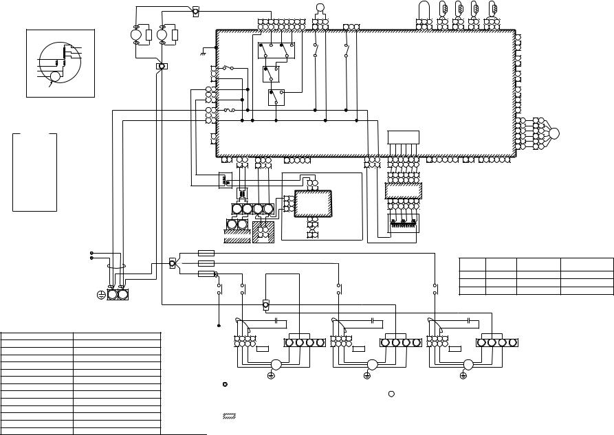
19
|
Fan motor inside |
7 |
S.K |
|
43F1 |
||
|
wiring diagram |
8 |
|
|
|
|
|
|
YEL |
WHI |
|
|
BLU |
|
|
BLK |
ORN |
|
|
WHI |
|
|
|
GRY |
49F |
|
|
RED |
|
|
|
|
Motor over heating |
|
|
|
protection switch |
|
|
|
Color |
|
|
|
indication |
|
|
|
|
RED : RED |
|
|
|
|
WHI |
: WHITE |
|
|
|
YEL |
: YELLOW |
|
|
|
BLU |
: BLUE |
|
|
|
BLK |
: BLACK |
|
|
|
GRY : GRAY |
|
|
|
|
PNK : PINK |
|
|
|
|
ORN : ORANGE |
|
|
|
|
BRW : BROWN |
|
|
|
|
GRN : GREEN |
|
|
|
|
|
|
|
RED |
WHI |
|
|
Closed-end |
WHI |
|
|
|
|
|
|
|
|
connector |
RED |
|
|
|
|
|
|
|
|
|
|
RED |
|
|
Indoor unit |
WHI |
|
|
|
earth screw |
||
|
|
|
R(L) |
S(N) |
|
|
|
Power supply |
|
|
|
|
single phase |
|
|
|
|
220-240V 50Hz |
|
|
|
|
220V 60Hz |
|
|
Symbol |
|
Parts name |
|
FM |
|
Fan motor |
|
|
RC |
|
Running capacitor |
||
TR |
|
Transformer |
|
|
TA |
|
Indoor temp sensor |
||
TC1,TC2,TC3 |
Temp sensor |
|
||
RY005~007 |
Fan motor control relay |
|||
RY001 |
|
Louver control relay |
||
RY002 |
|
Drain control relay |
||
PMV |
|
Pulse motor valve |
||
F1~3 |
|
Fuse for fan motor |
||
43F1,43F2 |
Fan motor control relay |
|||
DM |
|
Drain pump motor |
||
FS |
|
Float switch |
|
|
RED
6 RED
RED
7 |
Spark Killer |
43F2 |
S.K |
8 |
|
P301 |
|
(BLK) |
|
WHI |
|
|
|
|
|
|
7 |
1 |
|
|
|
|
|
3 |
FAN |
|
|
|
|
|
CN083 9 |
7 |
5 |
3 |
1 |
|
(WHI) |
9 |
7 |
5 |
3 |
1 |
|
|
H |
M |
L |
UL |
|
RY007 |
|
|
|
|
(Option) |
|
|
|
|
|
|
DM |
|
|
|
|
1 |
3 |
DP |
|
|
LM |
CN068 |
|
|
CN033 |
||
1 |
3 |
(BLU) |
1 |
3 |
(GRN) |
|
|
TA |
TCJ |
TC2 |
|
TC1 |
|
|||
1 |
3 |
1 |
2 |
1 |
2 |
1 |
2 |
1 |
|
3 |
1 |
3 |
1 |
2 |
1 |
2 |
1 |
2 |
1 |
2 |
3 |
CN030 |
CN104 |
CN102 |
CN101 |
CN100 |
1 |
|
|
(RED) |
(YEL) |
(RED) |
(BLK) |
(BRW) CN080 |
|
||
2 |
PNL |
||||||
FS |
|
|
|
(GRN) |
|||
|
|
|
3 |
|
|||
|
|
|
|
|
|
RY002 |
RY001 |
CN073 |
1 |
EXCT |
RY004 |
|
(RED) |
2 |
|
RY006 |
|
|
|
|
(GRY) |
|
CN070 |
1 |
FILTER |
CN304 |
|
(WHI) |
2 |
|
|
|
|
|
|
|
1 |
1 |
RY005 |
Control P.C. board |
|
1 |
|
|
|
|
|
|
|
|
(YEL) |
for Indoor unit |
CN081 |
2 |
|
|
|
|
|
|
3 |
3 |
|
MCC-1403 |
3 |
|
|
|
|
|
|
|
CN309 |
(BLK) |
|
|
|
|
||||
|
|
|
|
4 |
|
|
|
|
|||
AC IN |
RED 1 |
|
|
|
|
|
|
|
|
||
1 |
FUSE |
|
|
5 |
|
|
|
|
|||
|
|
|
|
|
|
|
|
|
|
|
|
|
|
3 |
3 |
T5.0A 250V~ |
|
|
6 |
6 |
5 |
5 |
|
|
WHI |
CN067 |
|
|
|
||||||
|
|
|
|
|
|
5 |
5 |
2 |
2 |
|
|
|
|
|
|
(BLK) |
|
|
|
||||
|
|
|
|
|
CN082 |
4 |
4 |
1 |
1 |
|
|
|
|
|
|
|
Power supply |
PMV |
|||||
|
|
|
1 |
CN066 |
(BLU) |
3 |
3 |
3 |
3 |
||
|
|
|
|
||||||||
|
|
|
2 |
(WHI) |
circuit |
|
2 |
2 |
4 |
4 |
|
CN044 |
CN040 |
CN041 |
CN050 |
CN075 |
CN061 |
CN032 |
CN060 |
1 |
1 |
6 |
6 |
(BRW) |
(BLU) |
(BLU) |
(WHI) |
(WHI) |
(YEL) |
(WHI) |
(WHI) |
|
|
|
|
|
|
|
1 |
2 |
1 |
2 |
1 |
2 |
3 |
1 |
2 |
3 |
4 |
5 |
|
|
CN074 |
1 |
3 |
1 |
2 |
3 |
4 |
5 |
6 |
1 |
2 |
3 |
4 |
5 |
6 |
1 |
2 |
1 |
2 |
3 |
4 |
5 |
6 |
|
|
|
|
|
EMG |
1 |
2 CO 1 |
|
3 RC |
|
|
|
|
|
|
(WHI) |
1 |
3 |
1 |
2 |
3 |
4 |
5 |
6 |
|
|
|
|
|
|
FAN |
|
OPTION |
|
|
|
|||||||
|
|
|
TR |
|
BLU |
BLK |
|
BLK |
|
|
|
|
|
|
|
|
|
|
|
|
|
|
|
|
|
|
|
|
|
|
DRIVE |
|
|
|
|
|
|
|
|
||
|
|
|
|
BLU |
|
|
|
|
|
|
|
|
|
|
|
|
1 |
2 |
3 |
4 |
5 |
6 |
CN02 |
|
|
|
|
|
|
|
|
|
|
|
|
|
|
|
|||
|
|
|
|
|
|
|
|
|
|
|
|
|
|
1 |
2 |
Network Adapter |
|
|
1 |
2 |
3 |
4 |
5 |
6 |
(YEL) |
|
|
|
|
|
|
|
|
|
|
|
|
|
|
|
|
|
|
|
|
|
|
|
|
|
|
|
|
|
|
|
(Option) |
|
|
|
|
|
|
|
|
|
|
|
|
|
|
|
|
|
|
|
|
|
|
|
|
||
|
|
|
|
|
|
|
|
|
|
|
|
|
|
1 |
2 |
|
|
|
Sub P.C. board |
|
|
|
|
|
|
|
|
|
|
|
|
|
|
|
|
||||||
|
|
|
|
|
|
|
|
|
|
|
|
|
|
|
|
|
|
|
|
|
|
|
|
|
|
|
|
|
|
|
|
|
|
||||||||
|
|
|
Line Filter |
|
|
|
|
|
|
|
|
CN01(WHI) |
|
|
|
|
MCC-1520 |
|
|
|
|
|
|
|
|
|
|
|
|
|
|
|
|
|
|||||||
|
|
|
|
|
|
|
|
|
|
3 |
3 |
|
|
|
|
|
|
|
|
|
|
|
|
|
|
|
|
|
|
|
|
|
|
|
|
|
|
||||
|
|
|
|
|
|
|
|
|
|
CN02 |
|
|
|
|
|
1 |
2 |
3 |
4 |
5 |
6 |
CN01 |
|
|
|
|
|
|
|
|
|
|
|
|
|
|
|
||||
|
|
|
|
|
|
|
|
|
|
|
2 |
|
|
|
|
|
|
|
|
|
|
|
|
|
|
|
|
|
|
|
|
||||||||||
|
|
|
|
U1 |
U2 |
A |
|
B |
|
(BLU) |
|
|
|
|
|
1 |
2 |
3 |
4 |
5 |
6 |
(YEL) |
|
|
|
|
|
|
|
|
|
|
|
|
|
|
|
||||
|
|
|
|
|
1 |
1 |
|
|
|
|
|
|
|
|
|
|
|
|
|
|
|
|
|
|
|
|
|||||||||||||||
|
|
|
|
|
|
CN03(RED) |
|
|
|
|
|
|
|
|
|
|
|
|
|
|
|
|
|
|
|
|
|
|
|
|
|
||||||||||
|
|
|
|
|
|
|
|
|
|
|
|
|
|
|
|
|
|
|
|
|
|
|
|
|
|
|
|
|
|
|
|
|
|
|
|
|
|
||||
|
|
|
|
U1 |
U2 |
|
|
|
|
|
|
|
1 |
2 |
|
|
|
|
|
|
|
|
|
|
|
|
|
|
|
|
|
|
|
|
|
|
|
|
|
|
|
|
|
|
|
1 |
|
2 |
|
|
|
|
1 |
2 |
|
|
|
|
|
|
|
|
|
|
TR |
|
|
|
|
|
|
|
|
|
|
|
|
|
|
|
|||
|
|
|
|
|
|
|
|
|
|
|
|
|
|
|
MCC-1401 |
|
|
|
|
|
|
|
|
|
|
|
|
|
|
|
|
|
|
|
|
|
|
|
|
||
|
|
|
|
Outdoor unit |
1 |
|
2 |
|
|
|
|
X |
Y |
|
|
|
|
|
|
|
|
|
|
|
|
|
|
|
|
|
|
|
|
|
|
|
|
|
|||
|
|
|
|
|
|
|
|
|
|
|
|
|
|
|
|
|
|
|
|
|
|
|
|
|
|
|
|
|
|
|
|
|
|
|
|||||||
|
|
|
|
|
|
|
CN1 |
|
|
|
|
|
|
|
|
|
|
|
|
|
|
|
|
|
|
|
|
|
|
|
|
|
|
|
|
|
|
|
|
||
|
|
F1 |
T10.0A, 250V~ |
Remote Controller |
|
|
|
|
|
|
|
|
|
|
|
|
|
|
|
|
|
|
|
|
|
|
|
|
|
|
|
|
|
|
|
||||||
|
RED |
|
|
|
RED |
|
|
|
|
|
|
|
|
|
|
|
|
|
|
|
|
|
|
|
|
|
|
|
|
|
|
|
|
|
|
|
|||||
|
|
|
|
|
|
|
|
|
|
|
|
|
|
|
|
|
|
|
|
|
|
|
|
|
|
|
|
|
|
|
|
|
|
|
|
||||||
|
RED |
F2 |
T10.0A, 250V~ |
|
|
|
RED |
|
|
|
|
|
|
|
|
|
|
|
|
|
|
|
|
|
|
|
|
|
Terminal Fan motor Static pressure |
|
|||||||||||
8 |
|
|
|
|
|
|
|
|
|
|
|
|
|
|
|
|
|
|
|
|
|
|
|
|
|
Note |
|||||||||||||||
|
RED |
F3 |
|
|
|
|
|
|
|
|
|
|
|
|
|
|
|
|
|
|
|
|
|
|
|
|
|
|
|
|
|
|
No. |
|
|
wiring |
Pa (mmAg) |
||||
|
|
|
|
|
|
|
|
ORW |
|
|
|
|
|
|
|
|
|
|
|
|
|
|
|
|
|
|
|
|
|
|
|
|
|
||||||||
|
|
|
|
|
|
|
|
|
|
|
|
|
|
|
|
|
|
|
|
|
|
|
|
|
|
|
|
|
|
|
F1 |
|
|
|
YEL |
69(7) |
|
||||
|
T10.0A, 250V~ 5 |
|
|
|
|
|
|
|
|
|
|
|
|
|
|
|
|
|
|
|
|
|
|
|
|
|
|
|
|
|
|
|
|
|
|||||||
|
|
|
5 |
|
|
|
|
|
|
|
|
|
|
6 |
|
|
|
|
|
|
|
|
|
6 |
|
|
|
|
|
F2 |
|
|
|
BLU |
137(14) |
Setting from factory |
|||||
|
|
|
43F1 |
|
43F2 |
|
|
|
|
|
|
|
|
|
43F2 |
|
|
|
|
|
|
|
|
|
|
43F1 |
|
|
|
F3 |
|
|
|
ORN |
196(20) |
|
|||||
WHI |
|
|
3 |
|
|
3 |
|
|
|
|
|
|
|
|
|
|
4 |
|
|
|
|
|
|
|
|
|
4 |
|
|
|
|
|
|
|
|
|
|
|
|
|
|
|
|
|
|
|
|
|
|
5 |
|
|
|
|
|
|
|
|
|
ORW |
|
|
|
|
|
|
|
|
|
|
|
|
|
|
|
|
|
|
|
|
|
|
|
|
|
|
|
|
|
|
|
|
|
|
|
|
|
|
|
|
|
|
|
|
|
|
|
|
|
|
|
|
|
|
|
|
|
|
|
|
|
|
|
|
|
YEL |
|
|
|
|
|
|
|
|
|
|
|
|
|
|
|
|
|
|
|
|
|
ORW |
|
|
|
|
|
|
RC |
|
|
|
|
|
|
|
RC |
|
|
|
|
|
|
|
|
RC |
|
|
|
connector |
WHI |
RED |
GRY |
|
|
|
|
|
WHI |
RED |
GRY |
|
|
|
|
|
WHI |
RED |
GRY |
|
|
|
|
|
Closed-end |
|
|
|
|
|
|
|
|
|
|
|
|
|
|
|
|
|
|
|
|
|
|
|
|
|
1 |
2 |
3 |
4 |
4P |
F1 |
F2 |
F3 F4 |
1 |
2 |
3 |
4 |
4P |
F1 |
F2 |
F3 F4 |
1 |
2 |
3 |
4 |
4P |
F1 |
F2 |
F3 F4 |
|
1 |
2 3 |
4 |
(RED) |
1 |
2 |
3 |
4 |
(BLU) |
1 |
2 |
3 |
4 |
(WHI) |
||||||||||
|
WHI |
RED |
GRY |
|
FAN3 |
YEL |
BLU |
ORN |
WHI |
RED |
GRY |
|
FAN2 |
YEL |
BLU |
ORN |
WHI |
RED |
GRY |
|
FAN1 |
YEL |
BLU |
ORN |
FM3 FM2 FM1
|
1. |
|
Indicates the terminal bolock, letter. |
|
|
|
Letter at inside indicates the terminal number. |
||
|
2. A dotted line and broken line indicate |
|||
|
|
the wiring at side. |
||
|
3. |
|
|
indicate the control p.c. board. |
|
|
|
||
|
4. |
|
When installing the drain pump connector |
|
Sold separately |
|
|||
|
the froat switch connector to CN030 connector. |
|||
|
|
|||
5. A Position is connected to terminal block when change to static pressure. Exchange the lead wire of arrow
 position after check the terminal number as figure and lead wire's color of fan motor.
6.When midifiy the high tap, to care the static pressure are differ by 50Hz or 60Hz.
AP0961H AP0721H,-MMD Model:

20
|
|
|
|
|
|
|
|
|
|
|
|
|
|
|
|
|
|
|
|
|
|
|
PMV |
|
|
|
|
|
|
|
|
|
|
|
|
|
|
|
|
|
|
|
|
|
|
|
|
|
|
|
|
FM |
|
|
|
|
|
|
|
|
|
|
|
|
|
|
|
|
LM |
|
|
|
|
|
|
|
|
|
|
|
|
|
|
|
|
|
|
|
|
|
|
|
|
|
|
|
|
|
6 |
4 |
3 |
1 |
2 |
5 |
|
1 |
2 |
3 |
4 |
5 |
|
|
|
|
|
|
|
||
|
|
|
|
|
|
|
|
|
|
|
|
|
|
|
|
|
|
|
|
|
|
|
|
|
|
|
|
|
|||||||||||
|
|
|
|
|
|
|
|
|
|
|
|
|
|
|
|
|
|
|
|
|
6 |
4 |
3 |
1 |
2 |
5 |
|
1 |
2 |
3 |
4 |
5 |
|
|
|
FS |
|
|
|
|
|
|
|
|
|
|
|
|
|
|
|
|
|
|
|
|
|
|
|
|
|
|
|
|
|
|
|
|
|
|
|
|
|
|
|
|
|
||
|
|
|
|
CN68 |
|
5 |
4 |
|
|
1 CN334 |
1 |
2 |
3 |
4 |
5 CN333 |
|
1 |
2 |
3 |
4 |
5 |
6 |
CN82 |
1 |
2 |
3 |
4 |
5 |
CN33 |
|
1 |
3 |
CN34 |
|
|||||
|
|
|
|
|
5 |
4 |
3 |
2 |
1 (WHI) |
1 |
2 |
3 |
4 |
5 |
(WHI) |
|
1 |
2 |
3 |
4 |
5 |
6 |
(BLU) |
1 |
2 |
3 |
4 |
5 |
(WHI) |
|
1 |
2 3 |
(RED) |
|
|||||
|
|
|
|
(BLU) |
|
|
|
|
|
|
|
|
|
|
|
|
|
|
|
|
|
|
|
|
|
|
|
|
|
|
|
|
|
|
|
|
|
|
|
|
|
|
|
1 |
1 |
RY302 |
|
|
|
|
|
|
|
|
|
|
|
|
|
|
|
|
|
|
|
|
|
|
|
|
|
|
|
|
|
CN104 |
1 |
1 |
|
|
|
DM |
|
2 2 |
|
|
|
|
|
|
|
|
|
|
|
|
|
|
|
|
|
|
|
|
|
|
|
|
|
|
|
|
|
|
|||||
|
|
|
|
|
|
|
|
|
|
|
|
|
|
|
|
|
|
|
|
|
|
|
|
|
|
|
|
|
|
|
|
|
(YEL) |
2 |
2 |
|
|||
|
|
|
|
3 |
3 |
|
|
|
|
|
|
|
|
|
|
|
|
|
|
|
|
|
|
|
|
|
|
|
|
|
|
|
|
|
|
|
|||
|
|
|
|
|
|
|
|
|
|
|
|
|
|
|
|
|
|
|
|
|
|
|
|
|
|
|
|
|
|
|
|
|
|
|
|
TA |
|
||
|
|
|
|
|
|
|
|
|
|
|
|
|
|
|
|
|
|
|
|
|
|
|
|
|
|
|
|
|
|
|
|
|
|
|
|
|
|
|
|
|
|
|
|
|
|
|
|
|
|
|
|
|
Motor drive |
|
|
|
|
|
|
|
|
|
|
|
|
|
|
|
|
|
|
CN102 |
1 |
1 |
|
||||
|
|
|
CN304 1 |
|
|
|
|
|
|
|
|
|
|
|
|
|
|
|
|
|
|
|
|
|
|
|
|
|
(RED) |
2 |
2 |
|
|||||||
|
|
|
RY303 |
|
|
|
|
|
|
|
circuit |
|
|
|
|
|
|
|
|
|
|
|
|
|
|
|
|
|
|
|
|
||||||||
|
|
|
(GRY) |
2 |
|
|
|
|
|
|
|
|
|
|
|
|
|
|
|
|
|
|
|
|
|
|
|
|
|
|
|
|
TCJ |
||||||
|
|
|
|
|
|
|
|
|
|
|
|
|
|
|
|
|
|
|
Indoor control P.C. board |
|
|
|
|
|
|||||||||||||||
|
|
|
|
|
3 |
|
|
|
|
|
|
|
|
|
|
|
|
Fuse |
|
|
|
|
|
CN101 |
1 |
1 |
|
||||||||||||
|
|
|
|
|
|
|
|
|
|
|
|
|
|
|
|
|
|
|
|
|
|
|
|
|
|
|
|
|
|
|
|
(BLK) |
2 |
2 |
|
||||
|
|
|
|
|
|
|
|
|
|
|
|
|
|
|
|
|
|
|
|
|
|
|
|
|
|
|
|
|
|
|
|
|
|
||||||
|
|
|
|
1 |
1 |
|
|
|
|
|
~ |
|
+ |
|
|
|
|
T3.15A |
|
|
|
DC20V |
|
|
|
|
|
|
|
|
|
|
|
TC2 |
|||||
RED |
|
|
|
|
|
|
|
|
|
|
|
|
|
|
|
|
Power |
|
|
|
|
|
|
|
|
|
|
|
|
||||||||||
|
|
CN67 |
|
|
|
|
|
|
|
|
|
|
|
|
|
|
|
|
|
|
|
|
|
|
|
|
|
|
1 |
1 |
|
||||||||
|
|
|
|
Fuse |
|
|
|
|
|
|
|
|
|
|
|
|
|
|
|
DC15V |
|
|
|
|
|
|
|
|
|
|
|
||||||||
|
|
2 |
2 |
|
|
|
|
|
|
|
|
|
|
|
|
|
|
supply |
|
|
|
|
|
|
|
|
|
|
CN100 |
|
|||||||||
|
|
|
(BLK) |
3 |
3 |
T6.3A |
|
|
|
|
~ |
|
– |
|
|
|
|
|
|
|
circuit |
|
DC12V |
|
|
|
|
|
|
|
|
|
(BRW) |
2 |
2 |
|
|||
|
WHI |
|
|
250V~ |
|
|
|
|
|
|
|
|
|
|
|
|
|
|
|
DC7V |
|
|
|
|
|
|
|
|
|
3 |
3 |
TC1 |
|||||||
|
|
|
|
|
|
|
|
|
|
|
|
|
|
|
|
|
|
|
|
|
|
|
|
|
|
|
|
|
|
|
|
|
|
|
|||||
|
|
|
|
|
|
|
|
|
|
|
|
|
|
|
|
|
|
|
|
|
|
|
|
|
|
|
|
|
|
|
|
|
|
|
|
||||
|
|
|
|
|
|
P301 |
|
|
|
|
|
|
|
|
|
|
|
|
|
|
|
|
|
|
|
|
|
|
|
|
|
|
|
|
|
|
|
|
|
|
|
|
BLK |
|
|
|
|
|
|
|
|
|
|
|
|
|
|
|
|
|
|
|
|
|
|
|
|
|
|
|
|
|
|
|
|
|
|||
|
|
|
|
|
|
|
|
|
|
|
|
|
|
|
|
|
|
|
|
|
|
|
|
|
|
|
|
|
|
|
|
|
|
1 |
|
|
|||
|
|
|
|
|
|
|
|
|
|
|
|
|
|
|
|
|
|
|
|
|
|
|
|
|
|
|
|
|
|
|
|
|
|
|
|
CN80 |
|
|
|
Indoor unit |
|
Flow selector |
|
|
1 |
CN66 |
|
|
|
|
|
|
|
|
|
|
|
|
|
|
|
|
|
|
|
|
|
|
|
|
|
|
|
|
|
2 PNL |
|
||
|
|
|
|
|
|
|
|
|
|
|
|
|
|
|
|
|
|
|
|
|
|
|
|
|
|
|
|
|
|
|
|
(GRN) |
|
||||||
|
unit earth |
|
|
2 |
(WHI) |
|
|
|
|
|
|
|
|
|
|
|
|
|
|
|
|
|
|
|
|
|
|
|
|
|
|
|
|
|
3 |
|
|
||
|
|
|
|
|
|
|
|
|
|
|
|
|
|
|
|
|
|
|
|
|
|
|
|
|
|
|
|
|
|
|
|
|
|
|
|
||||
|
|
screw |
|
|
|
|
|
|
|
|
|
|
|
|
|
|
|
|
|
|
|
|
|
|
|
|
|
|
|
|
|
|
|
|
|
|
|
|
|
Earth screw |
RED |
|
BLU |
1 |
1 |
CN40 |
|
|
|
|
|
|
|
|
|
|
|
|
|
|
|
|
|
|
|
|
|
|
|
|
|
|
|
|
|
CN73 |
1 |
EXCT |
|
|
BLU |
|
|
|
|
|
|
|
|
|
|
|
|
|
|
|
|
|
|
|
|
|
|
|
|
|
|
|
|
|
(RED) |
2 |
|
||||||
|
WHI |
2 |
2 |
(BLU) |
|
|
|
|
|
|
|
|
|
|
|
|
|
|
|
|
|
|
|
|
|
|
|
|
|
|
|
|
|
|
|
||||
|
|
Closed end |
BLK |
1 |
1 |
CN41 |
|
|
|
|
|
|
|
|
|
|
|
|
|
|
|
|
|
|
|
|
|
|
|
|
|
|
|
|
|
CN70 |
1 FILTER |
|
|
R(L) |
S(N) |
terminal |
|
|
2 |
(BLU) |
|
|
|
CN309 |
CN50 |
|
|
|
|
CN61 |
|
CN32 |
|
|
|
CN60 |
|
|
CN81 |
|
CN20 |
|
(WHI) |
2 |
|
|
|||||||
|
BLK |
|
|
|
|
|
|
|
|
|
|
|
|
|
|
|
|
|
|
|
|
||||||||||||||||||
Power supply |
|
3 |
3 |
|
|
|
|
(YEL) |
(WHI) |
|
|
|
|
(YEL) |
|
(WHI) |
|
|
|
(WHI) |
|
|
(BLK) |
|
(BLU) |
|
|
|
|
||||||||||
|
|
|
|
|
|
|
|
|
|
|
|
|
|
|
|
|
|
|
|
|
|
|
|
|
|
|
|
|
|
|
|
|
|
|
|
|
|
||
single phase |
|
|
|
|
|
1 |
2 |
3 |
|
1 |
2 3 |
4 |
5 |
|
1 |
2 |
3 4 |
5 |
6 |
1 |
2 |
|
1 |
2 3 |
4 5 6 |
|
1 |
2 |
3 |
4 |
5 |
1 2 3 4 |
5 |
|
|
|
|
||
200-240V 50Hz |
|
|
|
|
|
|
|
|
|
|
|
|
|
||||||||||||||||||||||||||
200V 60Hz |
|
|
|
|
|
1 |
2 |
3 |
|
|
|
|
|
|
|
|
T10 |
|
|
Fandrive |
|
|
|
Option |
|
|
|
|
|
|
GRL |
|
|
|
|
|
|||
|
|
|
|
|
|
|
|
|
|
|
|
|
|
|
TR |
CN01 1 |
2 |
Network |
|
|
|
|
|
|
|
|
|
|
|
|
|
|
|
|
|
||||
|
|
|
|
|
|
|
|
|
|
|
|
|
|
|
adaptor |
|
|
|
|
|
|
|
|
|
|
|
|
|
|
|
|
|
|||||||
|
|
|
U1 U2 |
A B |
|
|
|
|
|
|
|
|
|
|
|
|
|
|
|
|
|
|
|
|
|
|
|
|
|
|
|
||||||||
|
|
|
|
|
|
|
|
|
|
|
|
|
(WHI) |
1 |
2 |
(Option) |
|
|
|
|
|
|
|
|
|
|
|
|
|
|
|
|
|
||||||
|
|
|
|
|
|
|
|
|
|
|
BLK |
|
|
|
|
3 |
3 |
Network |
|
|
|
|
|
|
|
|
|
|
|
|
|
Color identification |
|
||||||
|
|
|
|
|
|
|
|
|
|
|
|
|
|
|
|
|
|
|
|
|
|
|
|
|
|
|
|
|
|
||||||||||
|
|
|
|
|
|
|
|
|
|
|
|
|
|
|
|
2 |
2 |
adaptor |
|
|
|
|
|
|
|
|
|
|
|
|
|
RED : RED |
|
BLK |
: BLACK |
|
|||
|
|
|
|
|
|
|
|
|
|
|
|
|
|
|
|
1 |
1 |
P.C. board |
|
|
|
|
|
|
|
|
|
|
|
|
|
|
|
||||||
|
|
|
|
|
|
|
|
|
|
|
WHI |
|
|
|
|
|
|
|
|
|
|
|
|
|
|
|
|
|
WHI : WHITE |
|
GRY : GRAY |
|
|||||||
|
|
|
|
|
|
|
|
|
|
|
|
|
|
|
CN02 |
|
|
|
|
|
|
|
|
|
|
|
|
|
|
|
|
|
|
||||||
|
|
|
|
|
|
|
|
|
|
|
|
|
|
|
|
1 |
2 |
CN03 |
|
|
|
|
|
|
|
|
|
|
|
|
YEL : YELLOW |
PNK : PINK |
|
||||||
|
|
|
|
|
|
|
|
|
|
|
|
|
|
|
|
(BLU) |
|
|
|
|
|
|
|
|
|
|
|
|
BLU : BLUE |
|
ORN : ORANGE |
||||||||
|
|
|
|
|
|
|
|
|
|
|
|
|
|
|
|
1 |
2 (RED) |
|
|
|
|
|
|
|
|
|
|
|
|
|
|||||||||
|
|
|
|
|
|
|
|
|
|
|
|
|
|
|
|
|
|
|
|
|
|
|
|
|
|
|
|
|
|
BRW : BROWN |
GRN : GREEN |
|
|||||||
|
|
|
|
WHI |
BLK |
|
WHI |
|
BLK |
|
|
|
|
|
X Y |
|
|
|
|
|
|
|
|
|
|
|
|
|
|
|
|
|
|
|
|
||||
|
|
|
|
|
|
|
|
|
|
|
|
|
|
|
|
|
|
|
|
|
|
|
|
|
|
|
|
|
|
|
|
Symbol |
|
Parts name |
|
||||
|
|
U1 U2 |
|
|
|
CN1 |
|
|
|
|
CN001 |
|
|
|
|
|
|
|
|
|
|
|
|
|
|
|
|
|
|
|
|
|
|
|
|||||
|
|
|
|
|
|
|
|
|
|
|
|
|
|
|
|
|
|
|
|
|
|
|
|
|
|
|
|
|
|
FM |
Fan motor |
|
|
|
|||||
|
|
|
|
|
(WHI) |
|
|
|
|
(WHI) |
|
|
|
|
|
|
|
|
|
|
|
|
|
|
|
|
|
|
|
|
|
|
|
|
|||||
|
|
Outdoor unit |
|
1 |
2 |
|
|
|
1 |
2 |
|
|
|
|
|
|
|
|
|
|
|
|
|
|
|
|
|
|
|
|
|
|
TA |
Indoor temp sensor |
|
||||
|
|
|
1 |
2 |
|
|
|
1 |
2 |
|
|
|
|
|
1. |
indicates the terminal block, letter at inside |
|
|
|
|
|
TC,TC2,TCJ |
Temp sensor |
|
|
||||||||||||||
|
|
|
|
|
|
|
|
|
|
|
|
|
|
|
|
|
|
|
|
||||||||||||||||||||
|
|
|
|
|
|
|
|
|
|
|
|
|
|
|
|
|
|
indicates the terminal number. |
|
|
|
|
|
|
|
|
|
LM |
Louver motor |
|
|
||||||||
|
|
|
|
|
|
|
|
|
|
|
|
|
|
|
|
|
|
|
|
|
|
|
|
|
|
|
RY302 |
Drain control relay |
|
|
|||||||||
|
|
|
|
|
|
|
|
|
|
|
|
|
|
|
|
|
2. A dotted line and broken line indicate the wiring at site. |
|
|
|
|
|
|||||||||||||||||
|
|
|
|
|
|
|
|
|
|
|
|
|
|
|
|
|
Sold |
|
DM |
Drain pump motor |
|
|
|||||||||||||||||
|
|
|
|
Wired remote |
Adpter for wireless |
|
|
|
|
3. |
|
indicates the control P.C. board. |
|
|
|
|
|
|
|||||||||||||||||||||
|
|
|
|
|
|
|
|
|
|
|
|
separately |
FS |
Float switch |
|
|
|
||||||||||||||||||||||
|
|
|
|
|
controller |
|
remote controller |
|
|
|
|
|
|
|
|
|
|
|
|||||||||||||||||||||
|
|
|
|
|
|
|
|
|
|
|
|
|
|
|
|
|
|
|
|
|
|
|
|
|
|
|
|
|
|
|
|
|
|||||||
Model: |
.6-1-2 |
AP0181H, AP0151H,-MMC |
Type Ceiling Under |
AP0481H AP0361H, AP0271H, AP0241H, |
|
5 |
5 |
FM |
|
|
|
|
|
|
|
|
|||
4 |
4 |
|
|
|
|
|
1 |
1 |
PMV |
|
|
|
|
TA |
TCJ |
TC2 |
TC1 |
|||
|
|
1 |
2 |
3 |
6 |
4 |
3 |
1 |
2 |
5 |
|
|
|
|
|
|
|
|
|
|
|
|
|
|
|
|
|
|
|
1 |
2 |
3 |
|
6 |
4 |
3 |
1 |
2 |
5 |
|
|
|
|
|
|
|
|
|
|
|
|
|
|
|
|
|
|
|
|
|
|
|
|
|
|
|
|
|
|
|
|
|
CN334 |
5 |
4 |
|
2 |
1 |
|
CN333 1 |
3 |
|
5 |
1 |
2 |
3 |
4 |
5 |
6 |
|
|
|
|
|
|
1 |
|
3 |
|
1 |
1 |
|
1 |
1 |
|
1 |
1 |
|
1 |
|
3 |
|
|
|||
|
|
|
|
|
|
|
|
|
|
(WHI) |
5 |
4 |
3 |
2 |
1 |
|
(WHI) |
|
1 |
3 |
|
5 |
1 |
2 |
3 |
4 |
5 |
6 |
|
1 2 |
3 |
4 |
5 |
|
1 |
|
3 |
|
2 |
2 |
|
2 |
2 |
|
2 |
2 |
|
1 |
2 |
3 |
|
|
|
|
|
|
|
|
|
1 |
|
|
|
|
|
|
|
|
|
|
|
|
|
|
|
|
|
CN82 |
|
|
|
CN33 |
|
|
CN34 |
|
CN104 |
CN102 |
CN101 |
CN100 |
|
|
|||||||||||||
|
|
|
|
|
CN68 |
|
RY302 |
|
|
|
|
|
|
|
|
|
|
|
|
|
|
(BLU) |
|
|
|
(WHI) |
|
|
(RED) |
|
(YEL) |
|
(RED) |
|
(BLK) |
(BRW) |
|
|
||||||||||||||
|
|
|
|
|
|
|
|
|
|
|
|
|
|
|
|
|
|
|
|
|
|
|
|
|
|
|
|
|
1 |
|
||||||||||||||||||||||
|
|
|
|
|
(BLU) |
|
|
|
|
|
|
|
|
|
|
|
|
|
|
|
|
|
|
|
|
|
|
|
|
|
|
|
|
|
|
|
|
|
|
|
|
|
|
|
|
|
|
|
CN103 |
|
||
|
|
|
|
|
3 |
|
|
|
|
|
|
|
|
|
|
|
|
|
|
|
|
|
|
|
|
|
|
|
|
|
|
|
|
|
|
|
|
|
|
|
|
|
|
|
|
|
|
(GRN) |
2 |
|
||
|
|
|
|
|
|
|
|
|
|
|
|
|
|
|
|
|
|
|
|
|
|
|
|
|
|
|
|
|
|
|
|
|
|
|
|
|
|
|
|
|
|
|
|
|
|
|
|
|
|
|||
|
|
|
|
|
|
|
|
|
|
|
|
|
|
|
|
|
|
|
Motor drive |
|
|
|
|
|
|
|
|
|
|
|
|
|
|
|
|
|
|
|
|
|
|
|
|
|
|
|
|
|
|
|||
|
|
|
|
|
|
1 |
1 |
|
RY303 |
|
|
|
|
|
|
|
|
circuit |
|
|
|
|
|
|
|
|
|
|
|
|
|
|
|
|
|
|
|
|
|
|
|
|
|
|
|
|
CN080 |
1 |
|
|||
|
|
|
|
LM |
|
|
|
|
|
|
|
|
|
|
|
|
|
|
|
|
|
|
|
|
|
|
|
|
|
|
|
|
|
|
|
|
|
|
|
|
|
|
|
|
|
|
2 |
|
||||
|
|
|
|
|
|
|
|
|
|
|
|
|
|
|
|
|
|
|
|
|
|
|
|
|
|
|
|
|
|
|
|
|
|
|
|
|
|
|
|
|
|
|
|
|
|
|
|
(GRN) |
|
|||
|
|
|
|
|
|
3 |
3 |
|
|
|
|
|
|
|
|
|
|
|
|
|
|
|
|
|
|
|
|
|
|
|
|
|
|
|
|
|
|
|
Control P.C. board |
|
|
|
3 |
|
||||||||
|
|
|
|
|
|
|
|
|
|
|
|
|
|
|
|
|
|
|
|
|
|
|
|
|
|
|
|
|
|
|
|
|
|
|
|
|
|
|
|
|
|
|||||||||||
|
|
|
|
|
CN304 |
|
|
|
|
|
|
|
|
|
|
|
|
|
|
|
|
|
|
|
|
|
|
|
|
|
|
|
|
|
|
|
for Indoor unit |
|
|
|
|
|
|
|
||||||||
|
|
|
|
|
(GRY) |
|
FUSE |
|
|
|
|
|
|
|
|
|
|
|
|
|
FUSE |
|
|
|
|
|
|
|
|
|
|
|
|
|
MCC-1402 |
|
|
|
|
CN73 |
1 |
EXCT |
||||||||||
|
|
RED |
|
|
|
1 |
1 |
T6.3A 250V~ |
|
|
|
|
|
|
|
|
|
|
|
|
T3.15A 250V~ |
|
|
Power |
|
|
DC20V |
|
|
|
|
|
|
|
|
|
|
|
|
|
|
(RED) |
2 |
|||||||||
|
|
|
|
|
|
|
|
|
|
|
|
|
|
|
|
|
|
|
|
|
|
|
|
|
|
|
|
|
|
|
|
|
|
|
|
|
|
|
|
|
|
|
|
|
|
|
||||||
|
|
|
|
|
|
|
|
|
|
|
|
|
|
|
|
|
|
|
|
|
|
|
|
|
|
|
|
|
|
supply |
|
|
DC15V |
|
|
|
|
|
|
|
|
|
|
|
|
|
|
|
|
|
||
|
|
WHI |
|
|
|
|
|
|
|
|
|
|
|
|
|
|
|
|
|
|
|
|
|
|
|
|
|
|
|
|
|
DC12V |
|
|
|
|
|
|
|
|
|
|
|
|
|
|
CN70 |
1 |
|
|||
|
|
|
|
|
3 |
3 |
|
|
|
|
|
|
|
|
|
|
|
|
|
|
|
|
|
|
|
|
|
|
circuit |
|
|
|
|
|
|
|
|
|
|
|
|
|
|
|
|
|
||||||
|
|
|
|
|
|
|
|
|
|
|
|
|
|
|
|
|
|
|
|
|
|
|
|
|
|
|
|
|
DC7V |
|
|
|
|
|
|
|
|
|
|
|
|
|
|
|
||||||||
|
|
|
|
|
|
|
|
|
|
|
|
|
|
|
|
|
|
|
|
|
|
|
|
|
|
|
|
|
|
|
|
|
|
|
|
|
|
|
|
|
|
|
|
|
|
(WHI) |
2 |
|
||||
|
|
|
|
|
CN67 |
|
|
|
|
|
|
|
|
|
|
|
|
|
|
|
|
|
|
|
|
|
|
|
|
|
|
|
|
|
|
|
|
|
|
|
|
|
|
|
|
|
|
|
||||
|
|
|
|
|
|
|
|
|
|
|
|
|
|
|
|
|
|
|
|
|
|
|
|
|
|
|
|
|
|
|
|
|
|
|
|
|
|
|
|
|
|
|
|
|
|
|
|
|
|
|||
|
|
|
|
|
(BLK) |
|
|
|
|
|
|
|
|
|
|
|
|
|
|
|
|
|
|
|
|
|
|
|
|
|
|
|
|
|
|
|
|
|
|
|
|
|
|
|
|
|
|
|
|
|
||
21 |
|
|
|
|
P301 |
|
|
|
|
|
|
|
|
|
|
|
|
|
|
|
|
|
|
|
|
|
|
|
|
|
|
|
|
|
|
|
|
|
|
|
|
|
|
|
|
|
|
|
|
|
||
|
|
|
|
|
BLK |
|
|
|
|
|
|
|
|
|
|
|
|
|
|
|
|
|
|
|
|
|
|
|
|
|
|
|
|
|
|
|
|
|
|
|
|
|
|
|
|
|
|
|
|
|
||
|
|
|
|
|
|
|
|
|
|
|
|
|
|
|
|
|
|
|
|
|
|
|
|
|
|
|
|
|
|
|
|
|
|
|
|
|
|
|
|
|
|
|
|
|
|
|
|
|
|
|
||
|
|
Flow selector |
|
|
|
|
|
|
|
|
|
|
|
|
|
|
|
|
|
|
|
|
|
|
|
|
|
|
|
|
|
|
|
|
|
|
|
|
|
|
|
|
|
|
|
|
|
|
|
|
|
|
|
|
unit earth |
|
|
|
|
1 |
|
|
|
|
|
|
|
|
|
|
|
|
|
|
|
|
|
|
|
|
|
|
|
|
|
|
|
|
|
|
|
|
|
|
|
|
|
|
|
|
|
|
|
|
|
|
|
screw |
|
|
|
|
|
|
|
|
|
|
|
|
|
|
|
|
|
|
|
|
|
|
|
|
|
|
|
|
|
|
|
|
|
|
|
|
|
|
|
|
|
|
|
|
|
|
|
|
|
|
|
|
|
|
|
|
|
2 |
|
|
|
|
|
|
|
|
|
|
|
|
|
|
|
|
|
|
|
|
|
|
|
|
|
|
|
|
|
|
|
|
|
|
|
|
|
|
|
|
|
|
|
|
|
|
|
RED |
|
|
CN66 |
|
CN40 |
CN41 |
|
|
|
|
|
|
CN50 |
|
|
|
CN61 |
|
|
CN32 |
|
|
|
CN60 |
|
|
|
|
CN81 |
|
|
|
CN20 |
|
|
|
||||||||||||||
|
|
Closed-end |
|
|
(WHI) |
|
(BLU) |
(BLU) |
|
|
|
|
|
|
(WHI) |
|
|
|
(YEL) |
|
|
(WHI) |
|
|
|
(WHI) |
|
|
|
|
(BLK) |
|
|
|
(BLU) |
|
|
|
||||||||||||||
|
|
connector |
|
|
|
|
|
|
1 |
2 |
1 |
2 |
3 |
|
1 |
3 CN309 |
1 |
2 |
3 |
4 |
5 |
1 |
2 |
3 |
4 |
5 |
6 |
1 |
2 |
|
1 |
2 |
3 |
4 |
5 |
6 |
|
1 |
2 |
3 |
4 |
5 |
|
1 |
2 |
3 |
4 |
5 |
|
|
||
|
|
WHI |
|
|
|
|
|
|
|
|
|
|
|
|
||||||||||||||||||||||||||||||||||||||
|
|
|
|
|
|
|
|
1 |
2 |
1 |
|
3 |
|
1 |
3 |
(YEL) |
|
|
|
|
|
|
|
|
|
|
|
Fandrive |
|
|
Option |
|
|
|
|
|
|
|
|
|
|
|
|
|
|
|
|
|||||
|
|
|
|
|
|
|
|
|
|
|
|
|
|
|
|
|
|
|
|
|
|
|
|
|
|
|
|
|
|
|
|
|
|
|
|
|
|
|
|
|||||||||||||
|
R(L) |
S(N) |
|
|
|
|
BLU |
|
|
|
|
|
|
|
|
|
|
|
|
|
|
|
|
|
|
|
|
|
|
|
|
|
|
|
|
|
|
|
|
|
|
|
|
|
|
|
|
|
|
|
||
|
|
|
|
|
|
BLU |
|
|
|
|
|
|
|
|
|
|
|
|
|
|
|
|
|
|
|
|
|
|
|
|
|
|
|
|
|
|
|
|
|
|
|
|
|
|
|
|
|
|
|
|||
|
|
|
|
|
|
|
|
|
|
|
|
|
|
|
|
|
|
|
|
|
|
|
|
|
|
|
|
|
|
|
|
|
|
|
|
|
|
|
|
|
|
|
|
|
|
|
|
|
|
|
||
|
Power supply |
|
|
|
|
|
|
|
BLK |
|
|
|
|
|
|
|
|
|
|
|
|
|
|
|
|
|
|
|
|
|
|
|
|
|
|
|
|
|
|
|
|
|
|
|
|
|
|
|
|
|
|
|
|
single phase |
|
|
|
|
|
|
|
BLK |
|
|
|
|
|
|
|
|
|
1 |
2 |
|
|
|
|
|
|
|
|
|
|
|
|
|
|
|
|
|
|
|
|
|
|
|
|
|
|
|
|
|
|
||
|
220-240V 50Hz |
|
|
|
|
|
GRY |
|
|
|
|
|
|
|
|
|
|
|
|
|
|
|
|
|
|
|
|
|
|
|
|
|
|
|
|
|
|
|
|
|
|
|
|
|
|
|
|
|
||||
|
220V 60Hz |
|
|
|
|
|
|
|
|
|
|
|
|
TR |
|
|
|
1 |
2 |
|
|
|
|
|
|
|
|
|
|
|
|
|
|
|
|
|
|
|
|
|
|
|
|
|
|
|
|
|
|
|||
|
|
|
|
|
|
|
GRY |
|
|
|
|
|
|
|
|
|
|
|
|
|
|
|
|
|
|
|
|
|
|
|
|
|
|
|
|
|
|
|
|
|
|
|
|
|
|
|
||||||
|
|
|
|
|
|
|
|
|
|
|
|
|
|
|
|
|
|
|
|
|
|
|
|
|
|
|
|
|
|
|
|
|
|
|
|
|
|
|
|
|
|
|
|
|
|
|
|
|
|
|||
|
Indoor unit |
|
|
|
|
|
|
|
|
|
|
|
|
|
|
|
|
|
|
|
|
|
|
|
|
|
|
|
|
|
|
|
|
|
|
|
|
|
|
|
|
|
|
|
|
|
|
|
|
|||
|
|
|
|
|
|
|
|
|
|
|
BLK |
|
|
3 |
3 |
|
CN01(WHI) |
|
|
|
|
|
|
|
|
|
|
|
|
|
|
|
|
|
|
|
|
|
|
|
|
|
|
|
|
|
||||||
|
|
|
U1 |
U2 |
A |
B |
X |
Y |
|
|
|
|
|
|
CN02 |
|
|
|
|
|
|
|
|
|
|
|
|
|
|
|
|
1. Indicates the terminal bolock. |
|
|
||||||||||||||||||
|
|
|
|
|
|
|
|
|
|
2 |
|
|
|
|
|
|
|
|
|
|
|
|
|
|
|
|
|
|
||||||||||||||||||||||||
|
|
|
|
|
|
|
|
|
|
(BLU) |
|
|
|
|
|
|
|
|
|
|
|
|
|
|
|
|
|
|
||||||||||||||||||||||||
|
Earth screw |
|
|
|
|
|
|
|
|
|
|
|
|
|
|
1 |
1 |
|
|
|
|
|
|
|
|
|
|
|
|
|
|
|
|
|
Letter at inside indicates the terminal number. |
|||||||||||||||||
|
|
|
|
|
|
|
|
|
|
|
WHI |
|
|
|
|
|
|
|
|
|
|
|
|
|
|
|
|
|
|
|
|
|
||||||||||||||||||||
|
Color |
|
|
|
|
|
|
|
|
|
|
|
|
|
|
|
|
|
|
|
|
|
|
|
|
|
|
|
|
|
|
|
|
|
2. A dotted line and broken line indicate |
|
|
|||||||||||||||
|
|
|
|
|
|
|
|
|
|
|
|
|
|
|
|
|
|
|
|
|
|
|
|
|
|
|
|
|
|
|
|
|
|
|
|
|
|
|||||||||||||||
|
|
|
|
|
|
|
|
|
|
|
|
|
|
|
|
|
|
|
CN03(RED) |
|
|
|
|
|
|
|
|
|
|
|
|
|
|
the wiring at side. |
|
|
|
|
|
|
|
|||||||||||
indication |
|
|
|
|
|
|
|
|
|
|
|
|
|
|
|
|
|
|
|
|
|
|
|
|
|
|
|
|
|
|
|
|
|
|
|
|
|
|
|
|||||||||||||
RED : RED |
|
|
WHI |
|
BLK |
WHI |
BLK |
|
|
|
|
|
|
|
|
|
1 |
2 |
|
|
|
|
|
|
|
|
|
|
|
|
|
|
3. |
|
|
indicate the control p.c. board. |
|
|
||||||||||||||
WHI |
: WHITE |
|
|
|
|
|
|
|
|
|
|
|
|
|
|
|
|
|
|
|
|
|
|
|
|
|
|
|
|
|
|
|
|
|
|
|
|
|
|
|
|
|
|
|||||||||
U1 |
U2 |
|
|
|
|
|
|
|
|
|
|
|
|
|
|
|
|
|
1 |
2 |
|
|
|
|
|
|
|
|
|
|
|
|
|
|
|
|
|
|
|
|
|
|
|
|
|
|
|
|
|
|
||
YEL |
: YELLOW |
|
|
|
|
|
|
|
|
|
|
|
|
|
|
|
|
|
|
|
|
|
|
|
|
|
|
|
|
|
|
|
|
|
|
|
|
|
|
|
|
|
|
|
|
Parts name |
|
|
||||
|
1 |
2 |
|
|
1 |
2 |
|
|
|
|
|
|
|
|
|
|
|
|
|
|
|
|
|
|
|
|
|
|
|
|
|
|
|
|
|
Symbol |
|
|
|
|
|
|
|
|
|
|||||||
BLU |
: BLUE |
|
|
|
|
|
|
|
|
|
|
|
|
|
|
|
|
|
|
|
|
|
|
|
|
|
|
|
|
|
|
|
FM |
|
|
|
|
|
|
|
|
|
|
|||||||||
BLK |
: BLACK |
|
|
|
1 |
2 |
|
|
1 |
2 |
|
|
|
|
|
|
|
|
|
|
|
|
|
|
|
|
|
|
|
|
|
|
|
|
|
|
|
|
|
|
|
|
|
|
Fan motor |
|
|
|||||
GRY : GRAY |
Outdoor |
|
CN1 |
|
|
CN001 |
|
|
|
|
|
|
|
|
|
|
|
|
|
|
|
|
|
|
|
|
|
|
|
|
|
|
TA |
|
|
|
|
|
|
|
|
Indoor temp sensor |
|
|
||||||||
PNK : PINK |
|
(WHI) |
|
(WHI) |
|
|
|
|
|
|
|
Network Adapter |
|
|
|
|
|
|
|
|
|
|
|
|
TC1,TC2,TCJ |
|
|
|
|
Temp sensor |
|
|
||||||||||||||||||||
unit |
|
|
|
|
|
|
|
|
|
|
|
|
|
|
|
|
|
|
|
|
|
|
|
|
|
|
|
|||||||||||||||||||||||||
ORN : ORANGE |
|
|
|
|
|
|
|
|
|
|
|
|
|
|
|
|
|
|
(Option) |
|
|
|
|
|
|
|
|
|
|
|
|
|
PMV |
|
|
|
|
|
|
|
Pulse motor valve |
|
|
|||||||||
BRW : BROWN |
|
|
Wired remote |
|
Adapter for |
|
|
|
|
|
|
|
|
|
|
|
|
|
|
|
|
|
|
|
|
|
|
LM |
|
|
|
|
|
|
|
|
Lover motor |
|
|
|||||||||||||
|
|
|
|
|
|
|
|
|
|
|
MCC-1401 |
|
|
|
|
|
|
|
|
|
|
|
|
|
|
|
|
|
|
|
|
|
|
|
||||||||||||||||||
GRN : GREEN |
|
|
|
controller |
wireless remote |
|
|
|
|
|
|
|
|
|
|
|
|
|
|
|
|
|
|
|
|
RY303 |
|
|
|
|
|
|
|
Louver control relay |
|
|
||||||||||||||||
|
|
|
|
|
|
|
|
|
controller |
|
|
|
|
|
|
|
|
|
|
|
|
|
|
|
|
|
|
|
|
|
|
|
|
|
|
|
|
|
|
|
|
|
|
|
|
|
|
|
|
|
|
|
Model: |
.7-1-2 |
AP0091H, AP0071H,-MMK |
Type Wall High |
AP0241H AP0181H, AP0151H, AP0121H, |
|
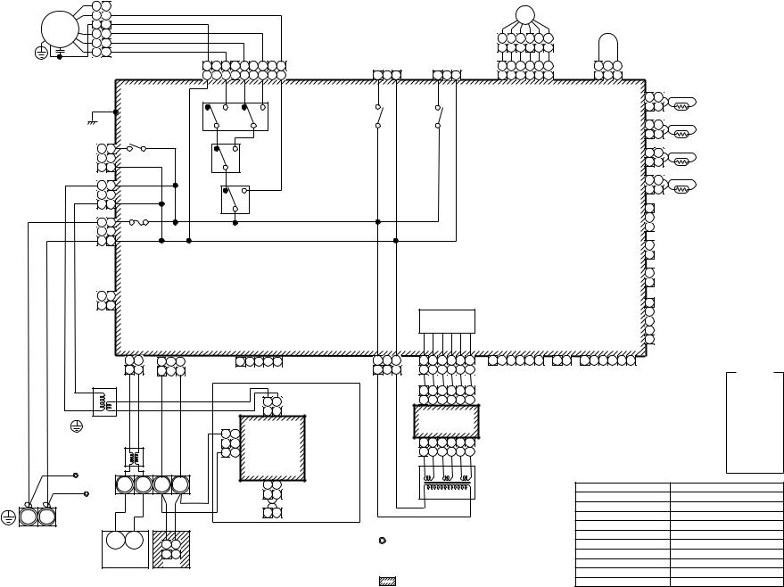
22
|
|
|
2 2 |
|
|
|
|
|
|
|
|
|
|
|
|
|
|
|
|
|
|
|
|
|
|
|
|
|
PMV |
|
|
|
|
|
|
|
|
|
|
||
|
FM |
|
3 |
3 |
|
|
|
|
|
|
|
|
|
|
|
|
|
|
|
|
|
|
|
|
|
|
|
|
|
|
|
|
|
|
|
|
|
|
|
|
|
|
|
4 |
4 |
|
|
|
|
|
|
|
|
|
|
|
|
|
|
|
|
|
|
|
|
|
|
|
|
|
|
|
|
|
|
|
|
|
|
|
|
|
|
|
|
|
|
|
|
|
|
|
|
|
|
|
|
|
|
|
|
|
|
|
|
|
|
|
|
6 |
4 |
3 |
1 |
2 |
5 |
|
|
|
|
|
|
|
|
||
|
|
|
5 |
5 |
|
|
|
|
|
|
|
|
|
|
|
|
|
|
|
|
|
|
|
|
|
|
|
|
|
|
|
|
|
|
|
||||||
|
|
|
|
|
|
|
|
|
|
|
|
|
|
|
|
|
|
|
|
|
|
|
|
|
|
6 |
4 |
3 |
1 |
2 |
5 |
|
|
|
|
|
|
|
|
||
|
RC |
|
6 |
6 |
|
|
|
|
|
|
|
|
|
|
|
|
|
|
|
|
|
|
|
|
|
|
|
PMV |
|
|
FS |
|
|
|
|
||||||
|
|
|
|
|
|
|
|
FAN |
RED BLK ORN BLU YEL |
|
|
|
|
|
|
|
|
|
|
|
|
|
|
|
|
|
|
|
|
|
|||||||||||
|
|
|
|
|
|
|
|
|
|
|
|
|
|
|
|
|
|
|
|
|
|
|
|
|
|
|
|
|
|
|
|
||||||||||
|
|
|
|
|
|
|
|
|
|
|
|
|
|
LM |
|
|
|
|
1 2 3 4 5 |
6 |
|
1 |
3 |
|
|
|
|
|
|||||||||||||
|
|
|
|
|
|
|
|
|
|
CN083 9 |
7 |
5 |
3 |
1 |
CN068 |
|
|
DP |
|
|
CN033 |
CN082 |
CN030 |
|
|
|
|||||||||||||||
|
|
|
|
|
|
|
|
|
|
(WHI) |
9 |
7 |
5 |
3 |
1 |
(BLU) |
1 |
3 |
|
|
1 |
|
3 |
(GRN) |
1 |
2 |
3 |
4 |
5 |
6 |
(BLU) |
1 |
2 3 |
(RED) |
|
|
|
|
|||
|
|
|
|
|
|
|
|
|
|
|
|
|
H |
|
M |
L |
UL |
|
|
|
|
|
|
|
|
|
|
|
|
|
|
|
|
|
|
|
1 |
1 |
TA |
|
|
|
|
|
|
|
|
|
|
|
|
|
|
RY007 |
|
|
|
|
|
|
|
|
|
|
|
|
|
|
|
|
|
|
|
|
|
|
|
CN104 |
|
||||
|
|
|
|
|
|
|
|
|
|
|
|
|
|
|
|
|
|
|
|
|
|
|
|
|
|
|
|
|
|
|
|
|
|
|
|
|
|||||
|
|
|
P301 |
|
|
|
|
|
|
|
|
|
|
|
|
|
|
|
|
|
|
|
|
|
|
|
|
|
|
|
|
|
|
|
(YEL) |
2 |
2 |
|
|
||
|
|
|
(BLK) |
|
|
|
|
|
|
|
|
|
|
|
|
|
RY002 |
|
|
RY001 |
|
|
|
|
|
|
|
|
|
|
|
|
|
|
|
1 |
1 |
TCJ |
|
||
|
|
|
|
|
|
|
|
|
|
|
|
|
|
|
|
|
|
|
|
|
|
|
|
|
|
|
|
|
|
|
|
|
|
|
|
CN102 |
|
||||
|
|
|
|
|
|
|
|
|
|
|
|
|
|
|
|
|
|
|
|
|
|
|
|
|
|
|
|
|
|
|
|
|
|
|
|
|
|
||||
|
|
|
|
|
|
|
RY004 |
|
|
|
|
|
|
|
|
|
|
|
|
|
|
|
|
|
|
|
|
|
|
|
|
|
|
|
(RED) |
2 |
2 |
|
|
||
|
|
|
1 |
1 |
|
|
|
|
|
|
|
RY006 |
|
|
|
|
|
|
|
|
|
|
|
|
|
|
|
|
|
|
|
|
|
|
|
TC2 |
|
||||
|
|
|
|
|
|
|
|
|
|
|
|
|
|
|
|
|
|
|
|
|
|
|
|
|
|
|
|
|
|
|
CN101 |
1 |
1 |
|
|||||||
|
|
|
|
|
|
|
|
|
|
|
|
|
|
|
|
|
|
|
|
|
|
|
|
|
|
|
|
|
|
|
|
|
|
|
|
|
|
||||
|
|
|
3 |
3 |
|
(GRY) |
|
|
|
|
|
|
|
|
|
|
|
|
|
|
|
|
|
|
|
|
|
|
|
|
|
|
|
|
(BLK) |
2 |
2 |
|
|
||
|
|
|
|
CN304 |
|
|
|
|
|
|
|
|
|
|
|
|
|
|
|
|
|
|
|
|
|
|
|
|
|
|
|
|
|
|
|
|
|
|
|||
|
|
|
|
|
|
|
|
|
|
|
|
|
|
|
|
|
|
|
|
|
|
|
|
|
|
|
|
|
|
|
|
|
|
|
|
|
|
TC1 |
|
||
|
|
|
|
|
|
|
|
|
|
|
|
|
|
|
|
|
|
|
|
|
|
|
|
|
|
|
|
|
|
|
|
|
|
|
|
CN100 |
1 |
1 |
|
||
|
|
|
1 |
1 |
|
|
|
|
|
|
|
|
|
|
RY005 |
|
|
|
|
|
|
|
|
|
|
Control P.C. board |
|
|
|
||||||||||||
|
|
|
|
|
|
|
|
|
|
|
|
|
|
|
|
|
|
|
|
|
|
|
|
(BRN) |
2 |
2 |
|
|
|||||||||||||
|
|
|
3 |
3 |
|
(YEL) |
|
|
|
|
|
|
|
|
|
|
|
|
|
|
|
|
|
|
|
for Indoor unit |
|
|
|
|
|
|
|
|
|||||||
|
|
|
|
CN309 |
|
|
|
|
|
|
|
|
|
|
|
|
|
|
|
|
|
|
|
|
MCC-1403 |
|
|
|
|
|
1 |
|
|
|
|||||||
|
|
|
|
|
|
|
|
|
|
|
|
|
|
|
|
|
|
|
|
|
|
|
|
|
|
|
|
|
CN080 |
|
|
|
|||||||||
|
AC IN |
RED |
|
|
|
|
|
|
|
|
|
|
|
|
|
|
|
|
|
|
|
|
|
|
|
|
|
|
|
|
|
|
|
|
|
2 |
PNL |
|
|
||
|
1 |
1 |
|
|
|
|
|
|
|
|
|
|
|
|
|
|
|
|
|
|
|
|
|
|
|
|
|
|
|
|
|
|
|
(GRN) |
|
|
|||||
|
|
|
|
|
|
FUSE |
|
|
|
|
|
|
|
|
|
|
|
|
|
|
|
|
|
|
|
|
|
|
|
|
|
|
|
|
|
|
3 |
|
|
|
|
|
|
|
3 |
3 |
T5.0A 250V~ |
|
|
|
|
|
|
|
|
|
|
|
|
|
|
|
|
|
|
|
|
|
|
|
|
|
|
|
|
|
|
|
|
|
|||
|
|
WHI |
|
|
|
|
|
|
|
|
|
|
|
|
|
|
|
|
|
|
|
|
|
|
|
|
|
|
|
|
|
|
|
CN073 |
1 |
|
|
|
|||
|
|
|
|
|
|
|
|
|
|
|
|
|
|
|
|
|
|
|
|
|
|
|
|
|
|
|
|
|
|
|
|
|
|
|
EXCT |
|
|||||
|
|
CN067 |
|
|
|
|
|
|
|
|
|
|
|
|
|
|
|
|
|
|
|
|
|
|
|
|
|
|
|
|
|
|
|
(RED) |
2 |
|
|||||
|
|
(BLK) |
|
|
|
|
|
|
|
|
|
|
|
|
|
|
|
|
|
|
|
|
|
|
|
|
|
|
|
|
|
|
|
|
|
|
|
|
|
||
|
|
CN066 |
|
|
|
|
|
|
|
|
|
|
|
|
|
|
|
|
|
|
|
|
|
|
|
|
|
|
|
|
|
|
|
CN070 |
1 |
FILTER |
|
||||
|
|
|
|
|
|
|
|
|
|
|
|
|
|
|
|
|
|
|
|
|
|
|
|
|
|
|
|
|
|
|
|
|
(WHI) |
2 |
|
||||||
|
|
(WHI) |
|
|
|
|
|
|
|
|
|
|
|
|
|
|
|
|
|
|
|
|
|
|
|
|
|
|
|
|
|
|
|
|
|
|
|||||
|
|
|
|
|
|
|
|
|
|
|
|
|
|
|
|
|
|
|
|
|
|
|
|
|
|
|
|
|
|
|
|
|
|
|
|
|
|
|
|||
|
|
|
1 |
1 |
|
|
|
|
|
|
|
|
|
|
|
|
|
|
|
|
|
|
|
|
|
|
|
|
|
|
|
|
|
|
|
|
|
1 |
|
|
|
|
|
|
2 |
2 |
|
|
|
|
|
|
|
|
|
|
|
|
|
|
|
|
|
|
|
|
|
|
|
|
|
|
|
|
|
|
|
|
|
|
|
|
|
|
|
|
|
|
|
|
|
|
|
|
|
|
|
|
|
|
|
|
|
|
|
|
|
|
|
|
|
|
|
|
|
|
|
|
|
2 |
|
|
|
||
|
|
|
|
|
|
|
|
|
|
|
|
|
|
|
|
|
|
|
|
|
Power supply |
|
|
|
|
|
|
|
|
|
CN081 |
|
|
|
|||||||
|
|
|
|
|
|
|
|
|
|
|
|
|
|
|
|
|
|
|
|
|
|
|
|
|
|
|
|
|
|
3 |
|
|
|
||||||||
|
|
|
|
|
|
|
|
|
|
|
|
|
|
|
|
|
|
|
|
|
|
|
|
|
|
|
|
|
|
(BLK) |
|
|
|
||||||||
|
|
|
|
|
|
|
|
|
|
|
|
|
|
|
|
|
|
|
|
|
|
|
circuit |
|
|
|
|
|
|
|
|
|
|
|
|
|
|||||
|
|
|
|
|
|
|
|
|
|
|
|
|
|
|
|
|
|
|
|
|
|
|
|
|
|
|
|
|
|
|
|
|
|
|
4 |
|
|
|
|||
|
|
|
|
|
|
CN040 |
CN041 |
|
|
|
|
CN050 |
|
|
|
|
|
|
|
|
|
|
|
|
CN061 |
|
|
|
CN032 |
CN060 |
|
|
|
|
|||||||
|
|
|
|
|
|
|
|
|
|
|
|
|
|
|
|
|
|
|
CN075 |
|
|
|
|
|
5 |
|
|
|
|||||||||||||
|
|
|
|
|
|
(BLU) |
(BLU) |
|
|
|
|
(WHI) |
|
|
|
|
|
|
|
|
|
|
(WHI) |
|
(YEL) |
|
|
|
(WHI) |
(WHI) |
|
|
|
|
|
||||||
|
|
|
|
|
|
|
|
|
|
|
|
|
|
|
|
|
|
|
|
|
|
|
|
|
|
|
|
|
|
|
|
|
|
|
|
|
|
|
|
|
|
|
|
|
|
|
|
1 |
2 |
1 |
2 |
3 |
RC |
|
|
1 |
2 |
3 4 |
5 |
CN074 |
1 |
3 |
1 |
2 |
3 |
4 |
5 |
6 |
1 |
2 |
3 |
4 |
5 |
6 |
|
1 2 |
1 2 3 4 5 6 |
|
|
|
|
||
|
|
|
|
|
|
1 |
2 |
1 |
|
3 |
|
|
|
|
|
|
|
(WHI) |
1 |
3 |
1 |
2 |
3 |
4 |
5 |
6 |
|
|
T10 |
|
|
|
FAN |
OPTION |
|
|
|
|
Color |
||
|
|
|
|
|
|
BLU |
BLU |
BLK |
|
BLK |
|
|
|
|
|
|
|
|
|
|
|
|
|
|
|
|
|
|
|
|
|
|
|
DRIVE |
|
|
|
|
|
indication |
|
|
|
|
|
|
|
|
|
|
|
|
|
|
|
|
|
|
1 |
2 |
3 |
4 |
5 |
6 |
CN02 |
|
|
|
|
|
|
|
|
|
|
|
RED : RED |
||||||
|
|
|
|
|
|
|
|
|
|
|
|
|
|
|
|
1 |
2 |
Network Adapter |
|
|
1 |
2 |
3 |
4 |
5 |
6 |
(YEL) |
|
|
|
|
|
|
|
|
|
|
|
WHI |
: WHITE |
|
|
|
|
|
|
|
|
|
|
|
|
|
|
|
|
|
|
|
|
|
|
|
|
|
|
|
|
|
|
|
|
YEL |
: YELLOW |
|||||||||
|
|
|
|
|
|
|
|
|
|
|
|
|
|
|
|
1 |
2 |
(Option) |
|
|
|
|
|
|
|
|
|
|
|
|
|
|
|
|
|
|
|
|
|
||
|
|
|
|
|
|
|
|
|
|
|
|
|
|
|
|
|
|
|
Sub P.C. board |
|
|
|
|
|
|
|
|
|
|
|
|
BLU |
: BLUE |
||||||||
|
|
|
TR |
|
|
|
|
|
|
|
|
|
|
|
|
|
|
|
|
|
|
|
|
|
|
|
|
|
|
|
|
||||||||||
|
|
|
|
|
|
|
|
|
|
|
|
|
|
|
|
|
|
|
|
|
|
|
|
|
|
|
|
|
|
|
BLK |
: BLACK |
|||||||||
|
|
|
|
|
|
|
|
|
|
|
|
|
|
CN01(WHI) |
|
|
|
MCC-1520 |
|
|
|
|
|
|
|
|
|
|
|
|
|
||||||||||
|
|
|
|
|
|
|
|
|
|
|
|
|
3 |
3 |
|
|
|
|
|
|
|
|
|
|
|
|
|
|
|
|
|
GRY : GRAY |
|||||||||
|
Flow selector |
|
|
|
|
|
|
|
|
|
|
|
|
|
|
|
|
|
|
|
|
|
|
|
|
|
|
|
|
|
|
|
|
|
|
||||||
|
|
|
|
|
|
|
|
|
|
CN02 |
|
|
|
|
1 |
2 |
3 |
4 |
5 |
6 |
CN01 |
|
|
|
|
|
|
|
|
|
|
|
PNK : PINK |
||||||||
|
unit earth |
|
|
|
|
|
|
|
|
|
|
|
2 |
|
|
|
|
|
|
|
|
|
|
|
|
|
|
|
|||||||||||||
|
|
|
|
|
|
|
|
|
|
|
|
|
|
|
|
|
|
|
|
|
|
|
|
|
|
|
ORN : ORANGE |
||||||||||||||
|
screw |
|
|
|
|
|
|
|
|
|
|
1 |
1 |
(BLU) |
|
|
|
|
1 |
2 |
3 |
4 |
5 |
6 |
(WHI) |
|
|
|
|
|
|
|
|
|
|
|
|||||
|
|
|
|
|
|
|
|
|
|
|
|
|
|
|
|
|
|
|
|
|
|
|
|
|
|
|
|
|
|
BRW : BROWN |
|||||||||||
|
|
Line Filter |
|
|
|
|
|
|
|
|
|
|
|
|
|
|
|
|
|
|
|
|
|
|
|
|
|
|
|
|
|
|
|
|
|
||||||
|
RED |
|
|
|
|
|
|
|
|
|
|
|
|
|
|
CN03(RED) |
|
|
|
|
|
|
|
|
|
|
|
|
|
|
|
|
|
|
|
|
|
GRN : GREEN |
|||
|
|
|
|
|
|
|
|
|
|
|
|
|
|
|
|
|
|
|
|
|
|
|
|
|
|
|
|
|
|
|
|
|
|
|
|
|
|
||||
|
Closed-end |
|
U1 |
U2 |
A |
|
B |
|
|
|
|
1 |
2 |
|
|
|
|
|
|
|
|
|
TR |
|
|
|
|
|
|
|
|
Symbol |
|
|
Parts name |
||||||
Indoor unit |
connector |
|
|
|
|
|
|
|
|
|
|
|
|
|
|
|
|
|
|
|
|
|
|
|
|
|
|||||||||||||||
WHI |
|
|
|
|
|
|
|
|
|
|
|
|
|
|
1 |
2 |
|
|
|
|
|
|
|
|
|
|
|
|
|
|
|
|
|
FM |
|
|
|
|
Fan motor |
|
|
earth screw |
|
|
|
|
|
|
|
|
|
|
|
|
|
|
|
|
|
|
|
|
|
|
|
|
|
|
|
|
|
|
|
|
|
|
|
|
|||||
|
|
|
|
|
|
|
|
|
|
|
|
|
|
|
|
|
|
|
|
|
|
|
|
|
|
|
|
|
|
|
|
|
|
|
|
|
|
||||
|
|
|
|
|
|
|
|
|
|
|
|
|
|
|
|
X Y |
MCC-1401 |
|
|
|
|
|
|
|
|
|
|
|
|
|
|
|
|
RC |
|
|
|
|
Running capacitor |
|
|
R(L) |
S(N) |
|
|
|
|
|
|
|
|
|
|
|
|
|
|
|
|
|
|
|
|
|
|
|
|
|
|
|
|
|
|
TR |
|
|
|
|
Transformer |
|
|||
|
|
|
|
|
|
|
|
|
|
|
|
|
|
|
|
|
|
|
|
|
|
|
|
|
|
|
|
|
|
|
|
|
|
|
|
||||||
|
|
|
|
|
|
|
|
|
|
|
|
|
|
|
|
|
|
|
|
|
|
|
|
|
|
|
|
|
|
|
|
|
|
|
|
|
|
||||
|
|
|
|
|
|
|
|
|
|
|
|
|
|
|
|
|
|
|
|
|
|
|
|
|
|
|
|
|
|
|
|
|
|
|
TA |
|
|
|
|
Indoor temp sensor |
|
Power supply |
|
|
U1 |
U2 |
|
|
|
|
|
|
|
|
|
|
1. Indicates the terminal bolock. |
|
|
|
|
|
TC1,TC2,TCJ |
|
|
Temp sensor |
|
||||||||||||||||
single phase |
|
|
1 |
|
2 |
|
|
|
|
|
|
|
|
|
|
|
|
RY001 |
|
|
|
|
Louver control relay |
|
|||||||||||||||||
220-240V 50Hz |
|
|
|
|
|
|
1 |
|
2 |
|
|
|
|
|
|
|
|
Letter at inside indicates the terminal number. |
RY002 |
|
|
|
|
Drain control relay |
|
||||||||||||||||
220V 60Hz |
|
|
Outdoor unit |
|
Remote Controller |
|
|
|
|
|
|
|
|
||||||||||||||||||||||||||||
|
|
CN1 |
|
|
2. A dotted line and broken line indicate |
|
|
|
RY004 |
|
|
|
|
Heater control relay |
|
||||||||||||||||||||||||||
|
|
|
|
|
|
|
|
|
|
|
|
|
|
||||||||||||||||||||||||||||
|
|
|
|
|
|
|
|
|
|
|
|
|
|
|
|
|
|
|
|
|
|
|
|||||||||||||||||||
|
|
|
|
|
|
|
|
|
|
|
|
|
|
|
|
|
|
|
the wiring at side. |
|
|
|
|
|
|
|
|
|
|
RY005~007 |
|
|
|
Fan motor control relay |
|||||||
|
|
|
|
|
|
|
|
|
|
|
|
|
|
|
|
|
|
3. |
|
|
indicate the control p.c. board. |
|
|
|
|
PMV |
|
|
|
|
Pulse motor valve |
|
|||||||||
Model: |
.8-1-2 |
AP0121H, AP0091H, AP0071H,-MML |
Type Cabinet Standing Floor |
AP0241H AP0181H, AP0151H, |
|
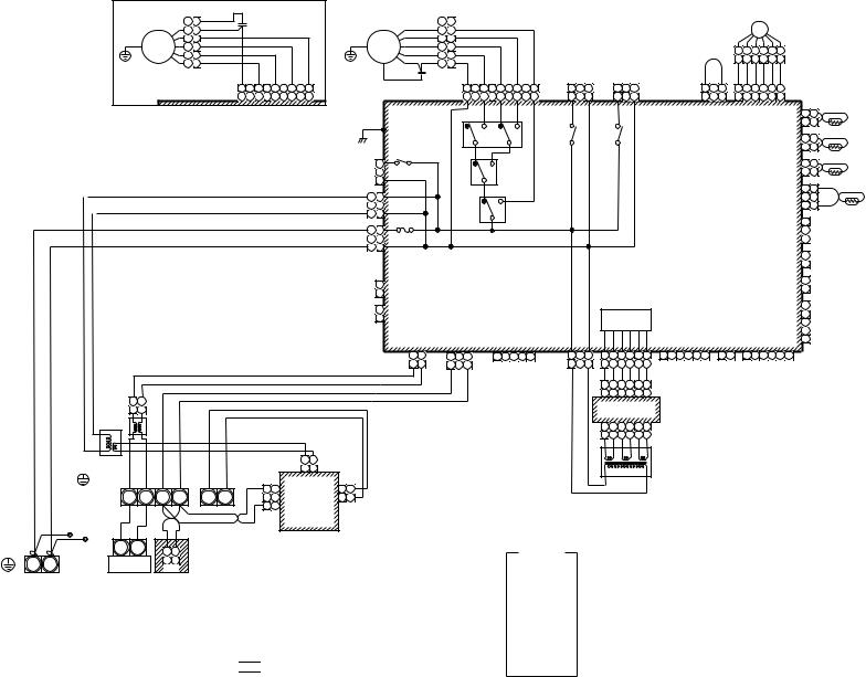
23
|
|
1 |
1 |
WHI |
|
|
|
|
|
|
|
|
|
|
|
|
|
|
|
|
|
|
|
|
|
|
|
|
|
|
|
|
|
|
|
|
|
|
|
|
|
|
|
|
|
|
|
|
|
|
RED |
|
RC |
|
|
|
|
|
|
|
|
|
|
|
|
|
|
|
|
|
|
|
|
|
|
|
|
|
|
|
|
|
|
|
|
|
|
|
|
|
|
|
|
|
|
||
|
|
3 |
3 |
|
|
|
|
|
|
|
2 |
2 |
|
|
|
|
|
|
|
|
|
|
|
|
|
|
|
|
|
|
|
|
|
|
|
|
|
|
PMV |
|
|
|
|
|
|
|||
|
|
|
|
|
|
|
|
|
|
|
|
|
|
|
|
|
|
|
|
|
|
|
|
|
|
|
|
|
|
|
|
|
|
|
|
|
|
|
|
|
|
|
||||||
GRN |
|
2 |
2 |
|
|
|
|
|
GRN |
|
|
|
4 |
4 |
|
|
|
|
|
|
|
|
|
|
|
|
|
|
|
|
|
|
|
|
|
|
|
|
|
|
|
|
|
|
|
|
|
|
FM |
4 |
4 |
|
|
|
|
|
FM |
|
5 |
5 |
|
|
|
|
|
|
|
|
|
|
|
|
|
|
|
|
|
|
|
|
|
|
|
|
|
|
|
|
|
|
|
|
|
|
|||
|
|
|
|
|
|
|
|
|
|
|
|
|
|
|
|
|
|
|
|
|
|
|
|
|
|
|
|
|
|
|
|
6 |
4 |
3 |
1 |
2 |
5 |
|
|
|
|
|||||||
|
|
5 |
5 |
|
|
|
|
|
|
|
|
|
6 |
6 |
|
|
|
|
|
|
|
|
|
|
|
|
|
|
|
|
|
|
|
|
|
|
|
|
|
|
|
|
||||||
|
|
|
|
|
|
|
|
|
|
|
|
|
|
|
|
|
|
|
|
|
|
|
|
|
|
|
|
|
|
|
|
|
|
|
6 |
4 |
3 |
1 |
2 |
5 |
|
|
|
|
||||
|
|
6 |
6 |
|
|
|
|
|
|
|
RED |
|
3 |
3 |
|
|
|
|
|
|
|
|
|
|
|
|
|
|
|
|
|
|
|
|
|
|
|
|
|
|
|
|
||||||
|
|
|
|
|
|
|
|
WHI |
|
|
|
|
|
|
|
|
|
|
|
|
|
|
|
|
|
|
|
|
|
|
|
|
|
|
|
|
|
|
|
|
|
|
|
|||||
|
|
|
|
FAN |
RED BLK ORN BLU YEL |
RC |
|
|
FAN |
RED BLK ORN BLU YEL |
|
|
|
|
|
|
|
|
|
|
|
|
|
|
|
|
|
|
|
|
|
|
|
|
|
|||||||||||||
|
|
|
|
|
|
|
|
1 |
3 |
|
|
1 |
3 |
|
|
|
|
|
|
|
1 |
3 |
1 |
2 |
3 |
4 |
5 |
6 |
|
|
|
|
||||||||||||||||
|
|
|
|
CN083 9 |
7 |
5 |
3 |
1 |
|
|
|
CN083 9 |
7 |
|
5 |
3 |
|
1 |
CN068 |
|
|
|
CN033 |
|
|
|
|
|
|
|
|
|||||||||||||||||
|
|
|
|
(WHI) |
9 |
7 |
5 |
3 |
1 |
|
|
|
(WHI) |
9 |
7 |
|
5 |
3 |
|
1 |
(BLU) |
1 |
3 |
|
|
1 |
3 |
|
(GRN) |
|
|
|
|
1 2 |
3 |
1 |
2 3 |
4 |
5 6 PMV |
|
|
|
||||||
|
For AP0071BH,AP0091BH,AP0121BH |
|
|
|
|
|
|
|
RY007 |
H |
|
M |
L |
UL |
|
|
|
|
|
|
|
|
|
|
|
|
|
|
CN030 |
|
|
CN082 |
CN104 |
1 |
1 |
TA |
||||||||||||
|
|
|
|
|
|
|
|
|
|
|
|
|
|
|
|
|
|
|
|
|
|
|
|
|
|
|
|
|
|
|
|
|
|
|
(RED) |
|
|
(BLU) |
|
(YEL) |
2 |
2 |
|
|||||
|
|
|
|
|
|
|
|
|
R301 |
|
|
|
|
|
|
|
|
|
|
|
|
|
|
|
|
|
|
|
|
|
|
|
|
|
|
|
|
|
|
|
|
|
|
|||||
|
|
|
|
|
|
|
|
|
|
|
|
|
|
|
|
|
|
|
|
|
|
|
|
|
|
|
|
|
|
|
|
|
|
|
|
|
|
|
|
|
|
|
|
|
|
|
||
|
|
|
|
|
|
|
|
|
(BLK) |
|
|
|
|
|
|
|
|
|
|
|
|
RY002 |
|
|
RY001 |
|
|
|
|
|
|
|
|
|
|
|
|
|
|
|
CN102 |
1 |
1 |
TCJ |
||||
|
|
|
|
|
|
|
|
|
|
|
|
|
|
|
|
|
|
|
|
|
|
|
|
|
|
|
|
|
|
|
|
|
|
|
|
|
|
|
|
|
|
|
|
|
||||
|
|
|
|
|
|
|
|
|
|
|
|
|
|
|
|
|
|
|
|
|
|
|
|
|
|
|
|
|
|
|
|
|
|
|
|
|
|
|
|
|
|
|
|
(RED) |
2 |
2 |
|
|
|
|
|
|
|
|
|
|
|
|
1 |
RY004 |
|
|
|
|
|
RY006 |
|
|
|
|
|
|
|
|
|
|
|
|
|
|
|
|
|
|
|
|
|
|
|
|
|
1 |
1 |
TC2 |
|||
|
|
|
|
|
|
|
|
|
|
|
|
|
|
|
|
|
|
|
|
|
|
|
|
|
|
|
|
|
|
|
|
|
|
|
|
|
|
|
|
CN101 |
||||||||
|
|
|
|
|
|
|
|
|
|
|
|
|
|
|
|
|
|
|
|
|
|
|
|
|
|
|
|
|
|
|
|
|
|
|
|
|
|
|
|
|
||||||||
|
|
|
|
|
|
|
|
|
|
|
(GRY) |
|
|
|
|
|
|
|
|
|
|
|
|
|
|
|
|
|
|
|
|
|
|
|
|
|
|
|
|
|
|
|
|
(BLK) |
2 |
2 |
|
|
|
|
|
|
|
|
|
|
|
|
3 |
|
|
|
|
|
|
|
|
|
|
|
|
|
|
|
|
|
|
|
|
|
|
|
|
|
|
|
|
|
|
|
|
|
|
|
|
|
|
|
|
|
|
|
|
|
|
|
|
CN304 |
|
|
|
|
|
|
|
|
|
|
|
|
|
|
|
|
|
|
|
|
|
|
|
|
|
|
|
|
|
|
|
|
|
|
|
|
|
|
|
|
|
|
|
|
|
|
|
|
|
|
|
|
|
|
|
|
|
|
|
|
|
|
|
|
|
|
|
|
|
|
|
|
|
|
|
|
|
|
|
|
|
|
|
1 |
1 |
TC1 |
|
|
|
|
|
|
|
|
|
|
|
|
|
|
|
|
|
|
|
|
RY005 |
|
|
|
|
|
|
|
|
|
|
Control P.C. board |
|
|
|
|
|
CN100 |
||||||||||||
|
|
|
|
|
|
|
|
|
1 |
1 |
|
|
|
|
|
|
|
|
|
|
|
|
|
|
|
|
|
|
|
|
|
|
|
2 |
|
|
||||||||||||
|
|
|
|
|
|
|
|
|
|
|
|
|
|
|
|
|
|
|
|
|
|
|
|
|
|
|
|
|
|
|
|
(BRW) |
|
|
||||||||||||||
|
|
|
|
|
|
|
|
|
3 |
3 |
(YEL) |
|
|
|
|
|
|
|
|
|
|
|
|
|
|
|
|
|
|
|
|
for undoor unit |
|
|
|
|
|
|
|
|
3 |
3 |
|
|||||
|
|
|
|
|
|
|
|
|
CN309 |
|
|
|
|
|
|
|
|
|
|
|
|
|
|
|
|
|
|
|
|
MCC-1403 |
|
|
|
|
|
|
|
|
|
|
|
|||||||
|
|
|
|
|
|
|
|
|
AC IN |
|
|
|
|
|
|
|
|
|
|
|
|
|
|
|
|
|
|
|
|
|
|
|
|
|
|
|
|
1 |
|
|
||||||||
|
|
|
|
|
|
|
|
|
|
|
|
|
|
|
|
|
|
|
|
|
|
|
|
|
|
|
|
|
|
|
|
|
|
|
|
|
|
|
|
|
|
CN080 |
|
|
||||
|
|
|
|
|
|
|
|
|
1 |
1 |
|
|
|
|
|
|
|
|
|
|
|
|
|
|
|
|
|
|
|
|
|
|
|
|
|
|
|
|
|
|
|
|
|
2 |
PNL |
|
||
|
|
|
|
|
|
|
|
|
FUSE |
|
|
|
|
|
|
|
|
|
|
|
|
|
|
|
|
|
|
|
|
|
|
|
|
|
|
|
|
|
|
|
|
(GRN) |
|
|||||
|
|
|
|
|
|
|
|
|
|
|
|
|
|
|
|
|
|
|
|
|
|
|
|
|
|
|
|
|
|
|
|
|
|
|
|
|
|
|
|
|
|
|
3 |
|
|
|||
|
|
|
|
|
|
|
|
|
|
|
|
|
|
|
|
|
|
|
|
|
|
|
|
|
|
|
|
|
|
|
|
|
|
|
|
|
|
|
|
|
|
|
|
|
|
|
||
|
|
|
|
|
|
|
|
|
3 |
3 |
T5.0A 250V~ |
|
|
|
|
|
|
|
|
|
|
|
|
|
|
|
|
|
|
|
|
|
|
|
|
|
|
|
|
|
|
|
|
|
|
|
|
|
|
|
|
|
|
|
|
|
|
(BLK) |
|
|
|
|
|
|
|
|
|
|
|
|
|
|
|
|
|
|
|
|
|
|
|
|
|
|
|
|
|
|
|
|
|
|
|
|
|
||
|
|
|
|
|
|
|
|
|
|
|
|
|
|
|
|
|
|
|
|
|
|
|
|
|
|
|
|
|
|
|
|
|
|
|
|
|
|
|
|
|
|
|
CN073 |
1 |
|
|
||
|
|
|
|
|
|
|
|
|
|
|
CN067 |
|
|
|
|
|
|
|
|
|
|
|
|
|
|
|
|
|
|
|
|
|
|
|
|
|
|
|
|
|
|
|
|
EXCT |
||||
|
|
|
|
|
|
|
|
|
|
|
|
|
|
|
|
|
|
|
|
|
|
|
|
|
|
|
|
|
|
|
|
|
|
|
|
|
|
|
|
|
|
|
(RED) |
2 |
||||
|
|
|
|
|
|
|
|
|
|
|
|
|
|
|
|
|
|
|
|
|
|
|
|
|
|
|
|
|
|
|
|
|
|
|
|
|
|
|
|
|
|
|
|
|
|
|||
|
|
|
|
|
|
|
|
|
|
1 |
CN066 |
|
|
|
|
|
|
|
|
|
|
|
|
|
|
|
|
|
|
|
|
|
|
|
|
|
|
|
|
|
|
|
|
CN070 |
1 |
FILTER |
||
|
|
|
|
|
|
|
|
|
|
|
|
|
|
|
|
|
|
|
|
|
|
|
|
|
|
|
|
|
|
|
|
|
|
|
|
|
|
|
|
|
|
(WHI) |
2 |
|||||
|
|
|
|
|
|
|
|
|
|
2 |
(WHI) |
|
|
|
|
|
|
|
|
|
|
|
|
|
|
|
|
|
|
|
|
|
|
|
|
|
|
|
|
|
|
|
|
|
|
|||
|
|
|
|
|
|
|
|
|
|
|
|
|
|
|
|
|
|
|
|
|
|
|
|
|
|
|
|
|
|
|
|
|
|
|
|
|
|
|
|
|
|
|
|
|
|
|
||
|
|
|
|
|
|
|
|
|
|
1 |
CN044 |
|
|
|
|
|
|
|
|
|
|
|
|
|
|
|
|
|
|
|
|
|
|
|
|
|
|
|
|
|
|
|
|
|
|
1 |
|
|
|
|
|
|
|
|
|
|
|
|
|
|
|
|
|
|
|
|
|
|
|
|
|
|
Power supply |
|
|
|
|
|
|
|
|
|
|
|
|
|
|
2 |
|
|
|||||||
|
|
|
|
|
|
|
|
|
|
2 |
(BRW) |
|
|
|
|
|
|
|
|
|
|
|
|
|
|
|
|
|
|
|
|
|
|
|
|
|
|
CN081 |
|
|
||||||||
|
|
|
|
|
|
|
|
|
|
|
|
|
|
|
|
|
|
|
|
|
|
|
|
|
|
|
|
|
|
|
|
|
|
|
|
3 |
|
|
||||||||||
|
|
|
|
|
|
|
|
|
EMG |
|
|
|
|
|
|
|
|
|
|
|
|
|
|
|
|
|
circuit |
|
|
|
|
|
|
|
|
|
|
|
|
|
|
(BLK) |
|
|
||||
|
|
|
|
|
|
|
|
|
CN040 |
|
CN041 |
|
|
CN050 |
|
|
|
|
|
|
|
|
|
CN075 |
|
CN061 |
|
|
CN032 |
|
CN060 |
|
4 |
|
|
|||||||||||||
|
|
|
|
|
|
|
|
|
|
|
|
|
|
|
|
|
|
|
|
|
|
|
|
|
|
|
|
5 |
|
|
||||||||||||||||||
|
|
|
|
|
|
|
|
|
|
|
(BLU) |
|
(BLU) |
|
|
(WHI) |
|
|
|
|
|
|
|
|
|
|
(WHI) |
|
(YEL) |
|
|
(WHI) |
|
|
(WHI) |
|
|
|
|
|||||||||
|
|
|
|
|
|
|
|
|
|
|
1 |
2 |
|
1 |
2 |
3 |
|
1 |
2 |
3 |
4 |
5 |
CN074 |
1 |
3 |
1 |
2 |
3 |
4 |
5 |
6 |
1 |
2 |
3 |
4 |
5 |
6 |
1 |
2 |
1 |
2 |
3 |
4 |
5 |
6 |
|
|
|
|
|
|
|
|
|
|
|
|
|
|
1 |
2 |
|
1 |
|
3 |
|
|
|
|
|
|
(WHI) |
1 |
3 |
1 |
2 |
3 |
4 |
5 |
6 |
|
|
|
|
|
|
FAN |
|
OPTION |
|
|
|
|
||||
|
|
|
|
|
|
|
|
|
|
|
|
|
|
|
|
|
|
|
|
|
|
|
|
|
|
|
|
|
|
|
|
|
|
|
|
|
|
DRIVE |
|
|
|
|
|
|
|
|
|
|
RED |
WHI |
1 2
1 2
Network
adapter
TR 1 2 (Option)
1 2
|
|
|
|
|
|
|
|
|
|
CN01(WHI) |
|
|
Flow selector |
U1 |
U2 |
A |
B |
X |
Y |
3 |
3 |
CN02 |
1 |
1 |
|
unit earth |
|
2 |
2 |
2 |
||||||||
|
screw |
|
|
|
|
|
|
1 |
1 |
(BLU) |
CN03 |
|
|
|
|
|
|
|
|
|
|||||
|
|
|
|
|
|
|
|
|
|
|
(RED) |
|
|
Closed-end |
|
|
|
|
|
|
|
|
CN03(RED) |
|
|
RED |
connector |
|
|
|
|
|
|
|
|
MCC-1401 |
|
|
|
|
|
|
|
|
|
|
|
|
|
|
|
1 |
2 |
3 |
4 |
5 |
6 |
CN02 |
1 |
2 |
3 |
4 |
5 |
6 |
(YEL) |
Sub P.C. board |
|
|||||
|
MCC-1520 |
|
|
|||
1 |
2 |
3 |
4 |
5 |
6 |
CN01 |
1 |
2 |
3 |
4 |
5 |
6 |
(WHI) |
TR
Indoor unit |
WHI |
earth screw |
|
R(L) S(N)
Power supply single phase 220-240V 50Hz 220V 60Hz
U1 |
U2 |
1 |
2 |
|
Outdoor unit |
1 |
2 |
||
CN1 |
||||
|
|
|||
Remote Controller
1. Indicates the terminal bolock.
Letter at inside indicates the terminal number.
2.A dotted line and broken line indicate the wiring at side.
3. indicate the control p.c. board.
Color indication
RED : RED WHI : WHITE YEL : YELLOW BLU : BLUE BLK : BLACK GRY : GRAY PNK : PINK ORN : ORANGE BRW : BROWN GRN : GREEN
Symbol |
Parts name |
FM |
Fan motor |
RC |
Running capacitor |
TR |
Transformer |
TA |
Indoor temp sensor |
TC1,TC2,TCJ |
Temp sensor |
RY001 |
Louver control relay |
RY002 |
Drain control relay |
RY004 |
Heater control reley |
RY005~007 |
Fan motor control relay |
PMV |
Pulse motor valve |
Model: |
.9-1-2 |
AP0121BH, AP0091BH, AP0071BH,-MML |
Type Concealed Standing Floor |
AP0241BH AP0181BH, AP0151BH, |
|
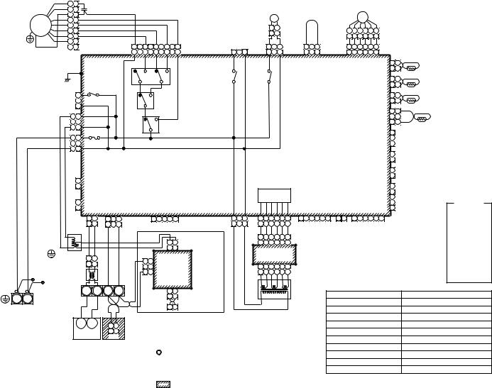
24
|
|
1 |
1 |
|
|
|
|
|
|
|
|
|
|
|
|
|
|
|
|
|
|
|
|
|
|
|
|
|
|
|
|
|
|
|
|
|
|
|
|
|
|
|
|
|
|
RC |
|
|
|
|
|
|
|
|
|
|
|
|
|
|
|
|
|
|
|
|
|
|
|
|
|
|
|
|
|
|
|
|
|
|
|
|
|
3 |
3 |
|
|
|
|
|
|
|
|
|
|
|
|
|
|
|
|
|
|
LM |
|
|
|
|
|
|
|
|
|
PMV |
|
|
|
|
|
|
||
|
|
4 |
4 |
|
|
|
|
|
|
|
|
|
|
|
|
|
|
|
|
|
|
|
|
|
|
|
|
|
|
|
|
|
|
|
|
|
||||
|
|
|
|
|
|
|
|
|
|
|
|
|
|
|
|
|
|
|
|
|
|
|
|
|
|
|
|
|
|
|
|
|
|
|
|
|
||||
|
|
|
|
|
|
|
|
|
|
|
|
|
|
|
|
|
|
|
|
|
|
|
|
|
|
|
|
|
|
|
|
|
|
|
|
|
|
|
||
|
FM |
5 |
5 |
|
|
|
|
|
|
|
|
|
|
|
|
|
|
|
|
|
|
2 |
1 |
|
|
|
|
|
|
|
|
|
|
|
|
|
|
|
|
|
|
|
6 |
6 |
|
|
|
|
|
|
|
|
|
|
|
|
|
|
|
|
|
|
|
|
|
|
|
|
|
6 |
4 |
3 |
1 |
2 |
5 |
|
|
|
|
||
|
|
|
|
|
|
|
|
|
|
|
|
|
|
|
|
|
|
|
|
2 |
1 |
|
|
|
|
|
|
|
|
|
|
|
||||||||
|
|
7 |
7 |
|
|
|
|
|
|
|
|
|
|
|
|
|
|
|
|
|
|
|
|
|
|
|
|
|
6 |
4 |
3 |
1 |
2 |
5 |
|
|
|
|
||
|
|
|
|
|
|
|
|
|
|
|
|
|
|
|
|
|
|
|
|
|
|
LM |
|
|
FS |
|
|
|
|
|
||||||||||
|
BRW 8 |
|
|
|
|
|
|
|
FAN |
RED BLK ORN BLU YEL |
|
|
DP |
|
1 |
3 |
|
1 |
|
1 |
2 |
|
|
|
PMV |
|
|
|
|
|||||||||||
|
|
|
|
|
|
|
|
|
CN083 9 |
7 |
|
5 |
3 |
1 |
CN068 |
|
|
|
|
CN033 |
3 |
CN030 |
3 4 5 6 CN082 |
|
|
|
||||||||||||||
|
|
|
|
|
|
|
|
|
(WHI) |
9 |
7 |
|
5 |
3 |
1 |
(BLU) |
1 |
3 |
|
|
1 |
3 |
|
(GRN) |
1 |
2 3 |
(RED) |
1 |
2 |
3 |
4 |
5 |
6 (BLU) |
|
|
|
||||
|
|
|
|
|
|
|
|
|
|
|
|
H |
|
M |
L |
UL |
|
|
|
|
|
|
|
|
|
|
|
|
|
|
|
|
|
|
CN104 |
1 |
1 |
TA |
|
|
|
|
|
|
|
|
|
|
|
|
|
RY007 |
|
|
|
|
|
|
|
|
|
|
|
|
|
|
|
|
|
|
|
|
|
|
|
|
|
|
|||
|
|
|
|
|
|
|
|
|
|
|
|
|
|
|
|
|
|
|
|
|
|
|
|
|
|
|
|
|
|
|
|
|
|
|
(YEL) |
2 |
2 |
|
|
|
|
|
P301 |
|
|
|
|
|
|
|
|
|
|
|
|
|
|
|
|
|
|
|
|
|
|
|
|
|
|
|
|
|
|
|
|
|
|
||||
|
|
|
|
|
|
|
|
|
|
|
|
|
|
|
|
|
|
|
|
|
|
|
|
|
|
|
|
|
|
|
|
|
|
|
|
|
|
|
||
|
|
(BLK) |
|
|
|
|
|
|
|
|
|
|
|
|
|
RY002 |
|
|
RY001 |
|
|
|
|
|
|
|
|
|
|
|
|
|
|
CN102 |
1 |
1 |
TCJ |
|
||
|
|
|
|
|
|
|
|
|
|
|
|
|
|
|
|
|
|
|
|
|
|
|
|
|
|
|
|
|
|
|
|
|
|
|
|
|
|
|||
|
|
|
|
|
|
|
|
|
|
|
|
|
|
|
|
|
|
|
|
|
|
|
|
|
|
|
|
|
|
|
|
|
|
|
|
(RED) |
2 |
2 |
|
|
|
|
|
1 |
|
|
RY004 |
|
|
|
|
|
RY006 |
|
|
|
|
|
|
|
|
|
|
|
|
|
|
|
|
|
|
|
|
|
1 |
1 |
TC2 |
|
|||
|
|
|
|
|
|
|
|
|
|
|
|
|
|
|
|
|
|
|
|
|
|
|
|
|
|
|
|
|
|
|
|
CN101 |
|
|||||||
|
|
|
|
|
|
|
|
|
|
|
|
|
|
|
|
|
|
|
|
|
|
|
|
|
|
|
|
|
|
|
|
|
|
|||||||
|
|
|
|
|
(GRY) |
|
|
|
|
|
|
|
|
|
|
|
|
|
|
|
|
|
|
|
|
|
|
|
|
|
|
|
|
|
(BLK) |
2 |
2 |
|
|
|
|
|
|
3 |
|
|
|
|
|
|
|
|
|
|
|
|
|
|
|
|
|
|
|
|
|
|
|
|
|
|
|
|
|
|
|
|
|
|
|
||
|
|
|
|
CN304 |
|
|
|
|
|
|
|
|
|
|
|
|
|
|
|
|
|
|
|
|
|
|
|
|
|
|
|
|
|
|
|
|
|
|
||
|
|
|
|
|
|
|
|
|
|
|
|
|
|
|
|
|
|
|
|
|
|
|
|
|
|
|
|
|
|
|
|
|
|
|
1 |
1 |
TC1 |
|
||
|
|
|
|
|
|
|
|
|
|
|
|
|
|
RY005 |
|
|
|
|
|
|
|
|
|
|
Control P.C. board |
|
|
|
|
|
CN100 |
|
||||||||
|
|
1 |
1 |
|
|
|
|
|
|
|
|
|
|
|
|
|
|
|
|
|
|
|
|
|
|
|
|
|
|
|
|
|
||||||||
|
|
|
|
|
|
|
|
|
|
|
|
|
|
|
|
|
|
|
|
|
|
|
|
|
|
|
(BRW) |
3 |
3 |
|
|
|||||||||
|
|
3 |
3 |
|
(YEL) |
|
|
|
|
|
|
|
|
|
|
|
|
|
|
|
|
|
|
|
for Indoor unit |
|
|
|
|
|
|
|
|
|||||||
|
|
|
CN309 |
|
|
|
|
|
|
|
|
|
|
|
|
|
|
|
|
|
|
|
|
MCC-1403 |
|
|
|
|
|
|
|
|
|
|
|
|||||
|
|
AC IN |
|
|
|
|
|
|
|
|
|
|
|
|
|
|
|
|
|
|
|
|
|
|
|
|
|
|
|
|
1 |
|
|
|
||||||
|
|
|
|
|
|
|
|
|
|
|
|
|
|
|
|
|
|
|
|
|
|
|
|
|
|
|
|
|
|
|
|
|
|
CN080 |
|
|
|
|||
|
|
1 |
1 |
|
|
|
|
|
|
|
|
|
|
|
|
|
|
|
|
|
|
|
|
|
|
|
|
|
|
|
|
|
|
|
|
2 |
PNL |
|
||
|
|
|
FUSE |
|
|
|
|
|
|
|
|
|
|
|
|
|
|
|
|
|
|
|
|
|
|
|
|
|
|
|
|
|
(GRN) |
|
||||||
|
|
|
|
|
|
|
|
|
|
|
|
|
|
|
|
|
|
|
|
|
|
|
|
|
|
|
|
|
|
|
|
|
|
3 |
|
|
|
|||
|
|
|
|
|
|
|
|
|
|
|
|
|
|
|
|
|
|
|
|
|
|
|
|
|
|
|
|
|
|
|
|
|
|
|
|
|
|
|||
|
|
3 |
3 |
T5.0A 250V~ |
|
|
|
|
|
|
|
|
|
|
|
|
|
|
|
|
|
|
|
|
|
|
|
|
|
|
|
|
|
|
|
|
|
|||
|
|
|
(BLK) |
|
|
|
|
|
|
|
|
|
|
|
|
|
|
|
|
|
|
|
|
|
|
|
|
|
|
|
|
|
|
|
|
|
|
|||
|
|
|
|
|
|
|
|
|
|
|
|
|
|
|
|
|
|
|
|
|
|
|
|
|
|
|
|
|
|
|
|
|
|
CN073 |
1 |
|
|
|
||
|
|
|
|
|
CN067 |
|
|
|
|
|
|
|
|
|
|
|
|
|
|
|
|
|
|
|
|
|
|
|
|
|
|
|
|
|
EXCT |
|
||||
|
|
|
|
|
|
|
|
|
|
|
|
|
|
|
|
|
|
|
|
|
|
|
|
|
|
|
|
|
|
|
|
|
|
(RED) |
2 |
|
||||
|
|
|
|
|
|
|
|
|
|
|
|
|
|
|
|
|
|
|
|
|
|
|
|
|
|
|
|
|
|
|
|
|
|
|
|
|
|
|
||
|
|
CN066 |
|
|
|
|
|
|
|
|
|
|
|
|
|
|
|
|
|
|
|
|
|
|
|
|
|
|
|
|
|
|
|
|
CN070 |
1 |
FILTER |
|
||
|
|
(WHI) |
|
|
|
|
|
|
|
|
|
|
|
|
|
|
|
|
|
|
|
|
|
|
|
|
|
|
|
|
|
|
|
|
(WHI) |
2 |
|
|||
|
|
|
|
|
|
|
|
|
|
|
|
|
|
|
|
|
|
|
|
|
|
|
|
|
|
|
|
|
|
|
|
|
|
|
|
|
||||
|
|
|
1 |
|
|
|
|
|
|
|
|
|
|
|
|
|
|
|
|
|
|
|
|
|
|
|
|
|
|
|
|
|
|
|
|
|
|
|
|
|
|
|
|
2 |
|
|
|
|
|
|
|
|
|
|
|
|
|
|
|
|
|
|
|
|
|
|
|
|
|
|
|
|
|
|
|
|
|
1 |
|
|
|
|
|
CN044 |
|
|
|
|
|
|
|
|
|
|
|
|
|
|
|
|
|
Power supply |
|
|
|
|
|
|
|
|
|
|
CN081 |
2 |
|
|
|
|||||
|
|
(BRW) |
|
|
|
|
|
|
|
|
|
|
|
|
|
|
|
|
|
|
circuit |
|
|
|
|
|
|
|
|
|
|
|
|
(BLK) |
3 |
|
|
Color |
||
|
|
|
1 |
|
CN040 |
|
|
|
|
|
|
|
|
|
|
|
|
|
|
|
|
|
|
|
|
|
CN061 |
|
CN032 |
|
|
CN060 |
4 |
|
|
|||||
RED |
WHI |
|
2 |
|
CN041 |
|
|
|
|
CN050 |
|
|
|
|
|
|
|
|
|
CN075 |
|
|
|
|
5 |
|
indication |
|||||||||||||
|
|
|
(BLU) |
(BLU) |
|
|
|
|
(WHI) |
|
|
|
|
|
|
|
|
|
|
(WHI) |
|
(YEL) |
|
(WHI) |
|
|
|
(WHI) |
|
|
RED : RED |
|||||||||
|
|
|
|
|
|
|
|
|
|
|
|
|
|
|
|
|
|
|
|
|
|
|
|
|
|
|||||||||||||||
|
|
|
|
|
1 |
2 |
1 |
2 |
3 |
RC |
|
|
1 |
2 |
3 4 |
5 |
CN074 |
1 |
3 |
1 |
2 |
3 |
4 |
5 |
6 |
1 |
2 |
3 4 |
5 6 |
1 2 |
|
1 2 |
3 |
4 |
5 6 |
|
|
|||
|
|
EMG |
|
|
|
|
|
WHI |
: WHITE |
|||||||||||||||||||||||||||||||
|
|
1 |
2 |
1 |
|
3 |
|
|
|
|
|
|
|
(WHI) |
1 |
3 |
1 |
2 |
3 |
4 |
5 |
6 |
|
|
|
|
FAN |
|
|
OPTION |
|
|
||||||||
|
|
|
|
|
BLU |
BLU |
BLK |
|
BLK |
|
|
|
|
|
|
|
|
|
|
|
|
|
|
|
|
|
|
|
|
DRIVE |
|
|
|
|
|
|
|
|
YEL |
: YELLOW |
|
|
|
|
|
|
|
|
|
|
|
|
|
Network Adapter |
|
|
1 |
2 |
3 |
4 |
5 |
6 |
CN02 |
|
|
|
|
|
|
|
|
|
|
|
|
BLU |
: BLUE |
||||
|
|
|
|
|
|
|
|
|
|
|
|
|
|
|
|
|
|
|
|
|
|
|
|
|
|
|
|
|
|
|
||||||||||
|
|
|
|
|
|
|
|
|
|
|
|
|
|
|
1 |
2 |
|
|
1 |
2 |
3 |
4 |
5 |
6 |
(YEL) |
|
|
|
|
|
|
|
|
|
|
|
|
BLK |
: BLACK |
|
|
|
|
|
|
|
|
|
|
|
|
|
|
|
|
1 |
2 |
(Option) |
|
|
Sub P.C. board |
|
|
|
|
|
|
|
|
|
|
|
|
GRY : GRAY |
|||||||
|
|
TR |
|
|
|
|
|
|
|
|
|
|
|
|
|
|
|
|
|
|
|
|
|
|
|
|
|
|
||||||||||||
|
|
|
|
|
|
|
|
|
|
|
|
|
CN01(WHI) |
|
|
|
|
|
|
|
|
|
|
|
|
|
|
PNK : PINK |
||||||||||||
|
|
|
1 |
2 |
|
|
|
|
|
|
|
|
|
|
|
MCC-1520 |
|
|
|
|
|
|
|
|
|
|
|
|
|
|||||||||||
|
Flow selector |
|
|
|
|
|
|
|
|
3 |
3 |
|
|
|
|
|
|
|
|
|
|
|
|
|
|
|
|
|
||||||||||||
|
|
|
|
|
|
|
|
|
|
|
|
|
|
|
|
|
|
|
|
|
|
|
|
|
|
|
|
|
|
|
|
|
|
ORN : ORANGE |
||||||
|
|
|
|
1 |
2 |
|
|
|
|
|
|
|
|
|
|
|
|
|
|
|
|
|
|
|
|
|
|
|
|
|
|
|
|
|
|
|||||
|
unit earth |
|
|
|
|
|
|
|
|
|
2 |
CN02 |
|
|
|
|
1 |
2 |
3 |
4 |
5 |
6 |
CN01 |
|
|
|
|
|
|
|
|
|
|
|
|
|||||
|
|
|
|
|
|
|
|
|
|
|
|
|
|
|
|
|
|
|
|
|
|
|
|
|
|
|
|
BRW : BROWN |
||||||||||||
|
screw |
Line Filter |
|
|
|
|
|
|
1 |
1 |
(BLU) |
|
|
|
|
1 |
2 |
3 |
4 |
5 |
6 |
(WHI) |
|
|
|
|
|
|
|
|
|
|
|
|
||||||
|
|
|
|
|
|
|
|
|
|
|
|
|
|
|
|
|
|
|
|
|
|
|
|
|
|
GRN : GREEN |
||||||||||||||
|
|
|
|
|
|
|
|
|
|
|
|
|
|
|
|
|
|
|
|
|
|
|
|
|
|
|
|
|
|
|
|
|
|
|
||||||
Indoor unit |
|
|
|
|
|
|
|
|
|
|
|
|
|
|
CN03(RED) |
|
|
|
|
|
|
|
|
|
|
|
|
|
|
|
|
|
|
|
|
|
|
|
||
earth screw |
Closed-end |
|
|
U1 |
U2 |
A |
|
B |
|
|
|
|
1 |
2 |
|
|
|
|
|
|
|
|
|
TR |
|
|
|
|
|
|
|
|
|
|
|
|
|
|
||
|
connector |
|
|
|
|
|
|
|
|
|
|
|
|
|
|
|
|
|
|
|
|
|
Symbol |
|
|
Parts name |
||||||||||||||
R(L) |
S(N) |
|
|
|
|
|
|
|
|
|
|
|
|
|
1 |
2 |
|
|
|
|
|
|
|
|
|
|
|
|
|
FM |
|
|
|
|||||||
|
|
|
|
|
|
|
|
|
|
|
|
|
|
|
|
|
|
|
|
|
|
|
|
|
|
|
|
|
|
|
|
|
|
|
|
Fan motor |
|
|||
|
|
|
|
|
|
|
|
|
|
|
|
|
|
|
X Y |
MCC-1401 |
|
|
|
|
|
|
|
|
|
|
|
|
|
|
|
|
|
|
|
|
|
|||
Power supply |
|
|
|
|
|
|
|
|
|
|
|
|
|
|
|
|
|
|
|
|
|
|
|
|
|
RC |
|
|
|
|
|
|
|
|
Running capacitor |
|
||||
|
|
|
|
|
|
|
|
|
|
|
|
|
|
|
|
|
|
|
|
|
|
|
|
|
|
|
|
|
|
|
|
|
|
|
||||||
|
|
|
|
|
|
|
|
|
|
|
|
|
|
|
|
|
|
|
|
|
|
|
|
|
|
|
|
|
|
|
|
|
|
|
|
|
||||
single phase |
|
|
|
|
|
|
|
|
|
|
|
|
|
|
|
|
|
|
|
|
|
|
|
|
|
|
|
|
TR |
|
|
|
|
|
|
|
|
Transformer |
|
|
220-240V 50Hz |
|
|
|
|
|
|
|
|
|
|
|
|
|
|
|
|
|
|
|
|
|
|
|
|
|
|
|
|
|
|
|
|
|
|
|
|
|
|||
220V 60Hz |
|
U1 |
U2 |
1 |
|
2 |
|
|
|
|
|
|
|
|
|
|
|
|
|
|
|
|
|
|
|
|
LM |
|
|
|
|
|
|
|
|
Lover motor |
|
|||
|
|
|
|
|
|
|
|
|
|
|
|
|
|
|
|
|
|
|
|
|
|
|
|
|
|
|
|
|
|
|
|
|
||||||||
|
|
|
Outdoor unit |
1 |
|
2 |
Remote Controller |
|
|
|
|
|
|
|
|
|
|
|
|
|
|
|
TA |
|
|
|
|
|
|
|
|
Indoor temp sensor |
|
|||||||
|
|
|
CN1 |
|
|
|
|
|
|
|
|
|
|
|
|
|
|
|
|
|
|
|
|
|
|
|
|
|||||||||||||
|
|
|
|
|
|
|
|
|
|
|
|
|
|
|
|
|
|
|
|
|
|
|
|
|
|
|
TC1,TC2,TCJ |
|
|
|
|
Temp sensor |
|
|||||||
|
|
|
|
|
|
|
|
|
|
|
|
|
|
|
|
|
|
|
|
|
|
|
|
|
|
|
|
|
|
|
|
|
|
|
||||||
|
|
|
|
|
|
|
|
|
|
|
|
1. |
|
Indicates the terminal bolock, letter. |
|
|
|
|
|
RY001 |
|
|
|
|
|
|
|
|
Louver control relay |
|
||||||||||
|
|
|
|
|
|
|
|
|
|
|
|
|
|
|
|
|
|
RY002 |
|
|
|
|
|
|
|
|
Drain control relay |
|
||||||||||||
|
|
|
|
|
|
|
|
|
|
|
|
|
|
Letter at inside indicates the terminal number. |
|
RY005~007 |
|
|
|
|
|
Fan motor control relay |
||||||||||||||||||
|
|
|
|
|
|
|
|
|
|
|
|
2. A dotted line and broken line indicate |
|
|
|
|
|
|
PMV |
|
|
|
|
|
|
|
|
Pulse motor valve |
|
|||||||||||
|
|
|
|
|
|
|
|
|
|
|
|
|
|
the wiring at side. |
|
|
|
|
|
|
|
|
|
|
|
|
|
|
|
|
|
|
|
|
|
|
|
|||
|
|
|
|
|
|
|
|
|
|
|
|
3. |
|
|
indicate the control p.c. board. |
|
|
|
|
|
|
|
|
|
|
|
|
|
|
|
|
|
|
|||||||
AP0181H, AP0151H,-MMF Model: |
Type Standing Floor .10-1-2 |
AP0561H AP0481H, AP0361H, AP0271H, AP0241H, |
|

|
|
|
|
|
|
|
|
|
|
|
RED |
|
|
|
|
|
Except 5HP, 6HP |
|
|
|
|
|
|
|
|
|
|
|
|
|
|
|
|
|
|
|
|
|
|
|
|
|
|
|
|
|
|
|
|
|
|
|
|
|
|
BLK |
|
|
|
|
|
|
|
(WHI) |
3 |
|
1 |
|
5 |
4 |
3 |
2 |
1 |
1 |
2 |
3 |
4 |
5 |
3 |
1 |
|
MAP1401H,-MMY Model: |
UnitOutdoor.2-2 |
||||||||
|
|
|
|
|
|
|
|
|
|
|
|
|
|
|
|
|
|
|
|
|
|
|
|
|
|
|
|
|
|
|
|
|
|
|
|
|
|
|
|
|
|
|
|
|
|
|
|
|
|
|
|
|
|
|
|
|
|
|
|
|
|
|
|
|
|
|
|
|
|
|
|
|
|
|
|
|
|
|
|
|
+ |
– |
|
|
|
||||||
|
|
1 |
2 |
|
|
|
|
|
|
|
|
|
|
|
|
|
|
|
|
|
|
|
|
|
|
|
|
|
|
|
|
|
|
|
|
|
|
|
|
|
|
|
|
|
|
|
|
|
|
|
|
|
|
|
|
|
|
|
|
|
|
|
|
|
FM |
|
|
|
|
|
|
|
|
|
|
|
|
|
|
|
|
|
|
|
|
|
|
|
|
|
|
|
|
1 |
2 |
|
|
BLU |
BLU |
|
WHI |
WHI |
|
BRN |
BLU |
ORN |
YEL |
WHI |
RED |
BRN |
BLU |
ORN |
YEL |
WHI |
Pressure |
|
Pressure |
Option |
|
|
Option |
|
Option |
|
Option |
|
|
Option |
|
|
|
|
|
|
|
|
|
|
RED |
WHI |
BLK |
|
|
|
|
|
|
|
|
|
|
|
|
|
|
|
|
YEL |
|
BLU |
|
|
|
|
|
||||||||||||||||||
|
|
|
|
|
|
|
|
RED |
BLK |
WHI |
|
RED |
BLK |
WHI |
|
|
|
|
|
|
|
|
|
|
|
|
|
|
|
|
|
|
|
|
|
|
|
|
|
|
|
|
|
|
|
|
|
|
|
|
|
|
|
|
|
|
|
|
|
|
|
|
|
|
|
|
|
|
|||||||||||||||||||||||
|
|
|
|
|
|
|
|
|
|
|
|
|
PMV1 |
|
|
|
PMV2 |
|
|
Sensor |
|
|
|
Sensor |
|
Board |
|
|
Board |
|
Board |
|
Board |
|
|
Board |
|
|
63H1 |
63H2 |
|
|
|
|
|
|
|
|
|
|
|
|
|
|
|
|
|
|
|
|
|
|
|
|
|
|
|
|
|
|
|
|
|
||||||||||||||||||
|
|
|
|
|
|
|
|
|
|
|
|
|
|
|
|
|
|
|
|
|
|
|
|
PS |
|
|
|
|
PD |
|
|
|
|
|
|
|
|
|
|
|
|
|
|
|
|
|
|
|
|
|
|
|
|
|
|
|
|
|
|
|
|
|
|
|
|
|
|
|
|
|
|
|
|
|
|
|
|
|
1 |
|
3 |
|
|
|
|
|
|||||
|
|
U1 U2 U3 U4 U5 U6 |
|
|
|
|
|
|
|
|
|
|
|
|
|
|
|
|
|
|
|
|
|
|
|
|
|
|
|
|
|
|
|
|
|
|
|
|
|
|
|
|
|
|
|
|
|
|
|
|
|
|
|
|
|
|
|
|
|
|
|
|
|
|
|
|
|
|
|
BLU |
|
|
|
|
|
|
|
|
|
|
1 |
|
3 |
|
|
|
|
|
|||
|
|
|
|
|
|
2 |
1 |
3 |
2 |
1 |
6 |
5 |
4 |
3 |
2 |
1 |
6 |
5 |
4 |
3 |
2 |
1 |
4 |
3 |
2 |
|
|
4 |
|
3 |
|
1 |
4 |
3 |
2 |
1 |
4 |
3 |
2 |
1 |
4 |
3 |
2 |
1 |
5 |
4 |
3 |
2 |
1 |
4 |
3 |
|
2 |
1 |
1 |
3 |
1 |
3 |
|
|
|
|
|
|
W |
V |
U |
– |
|
|
3 |
3 |
CN500 |
|
|
CN506(BLK) |
3 |
3 |
|
|
|
||||||||||
|
|
|
|
|
|
2 |
1 |
3 |
2 |
1 |
6 |
5 |
4 |
3 |
2 |
1 |
6 |
5 |
4 |
3 |
2 |
1 |
4 |
3 |
2 |
1 |
|
4 |
|
3 |
2 |
1 |
4 |
3 |
2 |
1 |
4 |
3 |
2 |
1 |
4 |
3 |
2 |
1 |
5 |
4 |
3 |
2 |
1 |
4 |
3 |
|
2 |
1 |
1 |
3 |
1 |
3 |
|
|
|
|
|
|
|
|
|
+ |
|
|
|
YEL |
1 |
1 |
|
(WHI) |
|
|
|
|
(BLU) |
1 |
1 |
|
|
|
|||||
|
|
|
|
|
|
CN01 CN03 |
|
|
CN300 |
|
|
|
CN301 |
|
|
CN500 |
|
|
|
CN501 |
|
CN508 |
|
CN509 |
|
CN510 |
|
CN513 |
|
|
CN512 |
|
CN306 |
CN308 |
3 |
3 |
BLU(BLK) |
TD1 |
FAN IPDU |
|
|
BLK |
|
|
|
Power supply |
|
|
|
|
|||||||||||||||||||||||||||||||||||||||||
|
|
|
|
|
|
(BLU) (WHI) |
|
|
(WHI) |
|
|
|
(WHI) |
|
|
(WHI) |
|
|
|
(RED) |
|
(RED) |
|
|
(BLK) |
|
(WHI) |
|
(BLU) |
|
|
(BLU) |
|
(WHI) |
(BLU) |
|
|
BLU(BLK) |
(YEL) |
P.C. Board |
5 |
5 |
WHI |
|
5 |
5 |
|
P.C. board for FAN |
5 |
5 |
|
|
|
||||||||||||||||||||||||||||||||||||||
|
|
|
|
|
|
|
|
|
|
|
|
|
|
|
|
|
|
|
|
|
|
|
|
|
|
|
|
|
|
|
|
|
|
|
|
|
|
|
|
|
|
|
|
|
|
|
|
|
|
|
|
|
|
|
|
|
CN502 |
1 |
1 |
|
|
|
MCC-896, 897 |
4 |
4 |
BLU |
|
4 |
4 |
CN503 MCC-1439 |
|
|
|
|
GRY |
|
|
||||||||||||||
|
|
|
|
|
|
|
|
|
|
|
|
|
|
|
|
|
|
|
|
|
|
|
|
|
|
|
|
|
|
|
|
|
|
|
|
|
|
|
|
|
|
|
|
|
|
|
|
|
|
|
|
|
|
|
|
|
(WHI) |
3 |
3 |
BLU(BLK) |
|
|
|
|
|
CN01 |
3 |
3 |
RED |
3 |
3 |
|
(WHI) |
|
|
|
|
CN501 |
3 |
3 |
|
|
|
||||||||
|
|
|
|
|
|
|
|
|
|
|
|
|
|
|
|
|
|
|
|
|
|
|
|
|
|
|
|
|
|
|
|
|
|
|
|
|
|
|
|
|
|
|
|
|
|
|
|
|
|
|
|
|
|
|
|
|
CN503 |
|
|
TD2 |
|
|
|
|
(WHI) |
2 |
2 |
2 |
2 |
|
|
|
|
|
|
|
|
(RED) |
|
|
RED |
|
|
||||||||
|
|
|
|
|
|
|
|
|
|
|
|
|
|
|
|
|
|
|
|
|
|
|
|
|
|
|
|
|
|
|
|
|
|
|
|
|
|
|
|
|
|
|
|
|
|
|
|
|
|
|
|
|
|
|
|
|
(PNK) |
1 |
1 |
BLU(BLK) |
(RED) |
|
|
|
|
|
1 |
1 |
PNK |
|
1 |
1 |
|
|
CN504 |
|
CN505(RED) |
1 |
1 |
|
|
||||||||||
|
|
U1 U2 |
U5 U6 |
|
|
|
|
|
|
|
|
|
|
|
|
|
|
|
|
|
|
|
|
|
|
|
|
|
|
|
|
|
|
|
|
|
|
|
|
|
|
|
|
|
|
|
|
|
|
|
|
|
|
|
|
|
|
|
|
|
|
|
|
|
|
|
|
|
|
|
|
|
|
|
1 |
2 |
3 |
4 |
5 |
1 |
2 |
3 |
4 |
5 |
|
|
|
|
|
||
|
|
BLU |
|
|
|
|
|
|
|
|
|
|
|
|
|
|
|
|
|
|
Interface Control P.C. Board |
|
|
|
|
|
|
|
|
|
|
|
|
|
|
|
|
|
|
|
|
|
|
BLK |
|
|
|
|
|
|
|
|
|
|
|
|
|
|
|
|
|
|
|
||||||||||||||||||||||||||||
|
|
Indoor |
Outdoor |
7 |
7 |
|
|
|
|
|
|
|
|
|
|
|
|
|
|
|
|
|
|
|
|
|
|
|
|
|
|
|
|
|
|
|
|
|
|
CN504 |
2 |
2 |
TS1 |
|
|
|
|
|
|
|
|
|
|
|
|
|
|
|
|
|
|
||||||||||||||||||||||||||||||
|
|
|
|
|
|
|
|
|
|
|
|
|
|
|
|
|
|
|
|
|
|
|
|
|
|
|
|
|
|
|
|
|
|
|
|
|
BLK |
|
|
|
|
|
|
|
|
|
|
|
|
|
|
|
|
|
|
1 |
2 |
3 |
4 5 |
|
|
|
|
|
|||||||||||||||||||||||||||
|
|
unit |
unit |
SV42 |
|
|
|
CR503 |
|
|
|
|
|
RY503 |
|
|
|
|
|
|
|
|
|
|
MCC-1429 |
|
|
|
|
|
|
|
|
|
|
|
|
|
|
|
|
|
|
|
|
|
|
|
(WHI) |
1 |
1 |
|
|
(GRY) |
|
|
|
|
|
|
|
|
|
|
|
|
|
|
|
|
|
|
|
|
|
|
|
BLU |
|
|
|
||||||||||
|
|
U1 U2 |
BLU 5 |
5 |
|
|
|
|
|
|
|
|
|
|
|
|
|
|
|
|
|
|
|
|
|
|
|
|
|
|
|
|
|
|
|
|
|
|
|
|
|
ON |
|
|
|
|
|
|
|
|
|
|
|
|
|
|
|
|
|
|
|
|
|
|
|
|
|
|
|
|
|
|
|
|
|
|
|
|
|
|
|
|
|
YEL |
|
|
|
||||
|
|
U3 U4 |
CN311(BLU) BLU 3 |
|
|
|
|
|
|
|
|
|
|
|
|
|
|
|
|
|
|
|
|
|
|
|
|
|
|
|
|
|
|
|
|
|
|
|
|
|
|
|
|
|
|
|
|
|
|
|
|
|
|
|
|
|
|
|
|
|
|
|
|
|
|
|
|
|
|
|
|
|
|
|
|
|
|
|
|
|
|
|
|
|
|
||||||
|
|
3 |
|
|
|
|
|
|
|
|
|
|
|
|
|
|
|
|
|
|
|
|
|
|
|
|
|
|
|
|
|
|
|
|
|
|
|
|
|
|
|
|
|
|
|
|
|
|
|
|
|
|
|
|
|
|
|
|
|
|
|
|
|
|
|
|
|
|
|
|
|
BLK WHI BLU |
RED |
PNK |
PNK |
RED |
BLU |
WHI |
BLK |
|
|
|
|
|
|||||||
|
|
Central remote |
SV41 |
|
|
|
|
|
|
|
|
|
|
|
|
|
|
|
|
|
|
|
|
|
|
|
|
|
|
|
|
|
|
|
|
|
|
|
|
|
|
|
SW30 |
|
|
|
|
|
|
|
|
|
|
|
|
2 |
2 |
BLK |
TE1 |
|
|
|
|
|
|
|
|
|
|
|
|
|
|
|
|
|
|||||||||||||||
|
|
controller |
|
|
|
CR502 |
|
|
|
|
|
RY502 |
|
|
|
|
|
|
|
|
|
|
|
|
|
|
|
|
|
|
|
|
|
|
|
|
|
|
|
|
|
|
|
|
|
|
|
|
CN505 |
|
|
|
|
|
|
|
|
|
|
|
|
|
|
|
|
|
|||||||||||||||||||||||||
|
|
|
|
BLU 1 |
1 |
|
|
|
|
|
|
|
|
|
|
|
|
|
|
|
|
|
|
|
|
|
|
|
|
|
|
|
|
|
|
|
|
|
|
|
|
|
|
|
|
|
|
|
|
|
|
|
|
|
|
(GRN) |
1 |
1 |
BLK |
(BLK) |
|
|
|
|
|
|
CN25 |
3 |
|
1 |
|
5 |
4 |
3 |
2 |
1 |
1 |
2 |
3 |
4 |
5 |
3 |
1 |
|
|
|
|||||
|
|
|
|
CN310(WHI) |
|
4 |
|
|
|
|
|
|
|
|
|
|
|
|
|
|
|
|
|
|
|
|
|
|
|
|
|
|
|
|
|
|
|
|
|
|
|
|
|
|
|
|
|
|
|
|
|
|
|
|
|
|
CN507 |
2 |
2 |
BLK |
TO |
|
|
|
YEL |
|
|
|
|
|
|
|
|
|
|
|
|
|
|
|
|
|
|
|
|
|
MAP1601H, |
|
|||
|
|
|
|
BLU |
1 |
3 |
|
CR504 |
|
|
|
|
|
RY504 |
|
|
|
|
|
|
|
|
6 |
|
|
|
|
|
|
|
|
|
|
|
|
|
|
|
|
|
|
|
|
|
|
|
|
|
|
|
|
|
|
(YEL) |
1 |
1 |
(BLK) |
|
|
|
|
|
1 |
1 |
|
|
|
|
|
CN06 |
|
|
CN18 |
|
CN17 |
|
|
||||||||||||||
|
|
|
|
1 |
|
|
|
|
|
|
|
|
|
|
|
|
|
|
|
|
|
|
|
|
|
|
|
|
|
|
|
|
|
|
|
|
|
|
|
|
|
|
|
|
|
|
|
|
|
|
|
|
|
CN523 |
3 |
3 |
|
|
TK4 |
|
|
|
|
|
|
|
|
|
|
|
|
|
|
BLK |
|
|
|
|
|
|
|
|
|
|
|||||||
|
|
|
|
SV51 BLU |
2 |
2 |
|
|
|
|
|
|
|
|
|
|
|
|
|
|
|
|
|
|
|
|
|
|
|
|
|
|
|
|
|
|
|
|
|
|
|
|
|
|
|
|
|
|
|
|
|
|
|
|
|
|
|
|
3 |
3 |
BLU(BLK) |
|
|
|
|
|
BLU |
|
|
2 |
2 |
CN26 |
|
|
(WHI) |
|
|
(RED) |
|
(BLK) |
|
|
|
||||||||
|
|
|
|
BLU |
1 |
1 |
|
|
|
|
|
|
|
|
|
|
|
|
|
|
|
|
|
|
|
|
|
|
|
|
|
|
|
|
|
|
|
|
|
|
|
|
|
|
|
|
|
|
|
|
|
|
|
|
|
|
CN514 |
|
|
TK1 |
|
|
|
|
|
|
3 |
3 |
(BLU) |
|
IPDU P.C. Board (1) |
|
|
|
|
|
|||||||||||||||
|
|
|
|
CN312(WHI) BLU 3 |
3 |
|
|
|
|
|
|
|
|
|
|
|
|
|
|
|
|
|
|
|
|
|
|
|
|
|
|
|
|
|
|
|
|
|
|
|
|
|
|
|
|
|
|
|
|
|
|
|
|
|
|
(BLK) |
1 |
1 |
BLU(BLK) |
(BLK) |
|
|
|
|
|
|
BLK |
|
W |
CN11 |
|
MCC-1502 |
|
|
|
|
BLK |
|
|
||||||||||||
|
|
|
|
SV2 BLU |
|
|
|
CR506 |
|
|
|
|
|
RY506 |
|
|
|
|
|
|
|
|
|
|
|
|
|
|
|
ON 1 2 3 4 |
ON 1 2 3 4 |
ON 1 2 3 4 |
ON 1 2 3 4 |
|
|
|
|
|
|
|
|
|
|
|
|
BLU(BLK) |
|
|
|
|
|
CM1 |
WHI |
|
V |
CN10 |
|
|
|
|
|
|
|
CN03 T |
|
WHI |
|
|
|||||||||||||||||||||||
|
|
|
|
|
1 |
1 |
|
|
|
|
|
|
|
|
|
|
|
|
|
|
|
|
|
|
|
|
|
|
|
|
|
|
SW11 |
|
|
SW12 |
|
SW13 |
|
SW14 |
|
|
|
|
|
|
|
|
|
CN515 |
|
|
|
|
TK2 |
|
|
|
|
|
|
YEL |
|
|
|
CN09 |
|
|
|
|
|
|
|
CN01 R |
|
RED |
|
|
|||||||||||||
|
|
|
|
CN324(RED)BLU 3 |
3 |
|
|
|
|
|
|
|
|
|
|
|
|
|
|
|
|
|
|
|
1 |
|
|
|
|
|
|
|
|
|
|
|
|
|
|
|
|
|
|
|
|
|
|
|
|
|
|
|
|
|
|
(GRN) |
1 |
1 |
BLU(BLK) |
(BLU) |
|
|
|
|
|
|
BLU |
|
|
|
CN22 |
|
CN15 CN13 |
|
|
|
|
|
|
|
|
||||||||||
|
|
|
|
SV3A |
|
|
|
CR507 |
|
|
|
|
|
RY507 |
|
|
|
|
|
|
|
|
|
|
|
|
|
ON 1 2 3 4 |
ON 1 2 3 4 |
ON 1 ON 1 2 3 4 |
ON 1 2 3 4 |
|
|
|
|
|
|
|
|
|
|
|
BLU(BLK) |
|
|
|
|
|
|
|
|
|
|
|
|
CN23 |
|
|
|
|
|
|
|
|
|
|
|
|
|
|
|||||||||||||||||||||
|
|
|
|
|
|
|
|
|
|
|
|
|
|
|
|
|
|
|
|
2 |
|
|
|
|
|
|
|
|
|
|
|
|
|
|
3 |
3 |
|
|
|
|
|
|
|
|
|
|
|
|
|
|
|
|
|
|
|
|
|
|
|
|
|
|
|
|
|
||||||||||||||||||||||||||
|
|
|
|
BLU |
1 |
1 |
|
|
|
|
|
|
|
|
|
|
|
|
|
|
|
|
|
|
|
|
|
|
|
|
|
|
|
|
|
|
|
|
|
|
|
|
|
|
|
|
|
|
|
|
|
|
|
|
|
CN516 |
|
|
TK3 |
|
|
|
|
|
|
|
|
|
|
|
|
|
|
|
|
|
|
|
CN21 |
|
|
CN20 |
|
|
|||||||
|
|
|
|
|
|
|
|
|
|
|
|
|
|
|
|
|
|
|
|
|
|
|
|
3 |
|
|
|
|
|
|
|
|
|
|
|
|
|
|
|
|
|
|
|
|
|
|
|
|
|
|
|
|
|
|
|
|
|
|
|
|
|
|
|
|
|
|
|
|
|
|
|
|
|
|
|
|
|
|
|
|
|
||||||||||
|
|
|
|
CN313(YEL) BLU |
|
|
|
|
|
|
|
|
|
|
|
|
|
|
|
|
|
|
(Srvice) |
|
|
|
|
|
|
SW06 |
|
|
SW07 |
|
SW08 |
|
SW09 |
|
SW10 |
|
|
|
|
|
|
|
(RED) |
|
|
BLU(BLK) |
(BLU) |
|
|
|
|
|
|
|
|
|
|
|
|
|
|
|
|
|
|
|
WHI |
|
|
WHI |
|
|
|
||||||||||||||
|
|
|
|
3 |
3 |
|
|
|
|
|
|
|
|
|
|
|
|
|
|
|
|
4 |
|
|
|
|
|
|
|
|
|
|
|
|
|
|
|
|
|
|
1 |
1 |
|
|
|
|
|
|
|
|
|
|
|
|
|
|
|
|
|
|
|
|
|
|
|
|
|||||||||||||||||||||||||
|
|
|
|
SV3B |
|
|
|
CR508 |
|
|
|
|
|
RY508 |
|
|
|
|
|
|
|
|
5 |
|
|
|
|
|
|
CN31 |
|
|
|
|
|
|
|
|
|
|
|
|
|
|
|
|
|
|
|
|
|
|
|
|
|
|
BLU(BLK) |
|
|
|
|
|
|
|
|
|
|
|
|
|
|
|
|
|
|
|
BLU |
|
Reactor |
|
|
|
|
||||||||
|
|
|
|
|
|
|
|
|
|
|
|
|
|
|
|
|
|
|
|
|
|
|
|
|
|
|
|
|
|
|
|
|
|
|
|
|
|
|
|
|
|
|
|
|
|
|
|
|
|
|
|
|
|
|
|
|
|
|
|
|
|
|
|
|
|
|
|
|
|
|
|
|
|
|
|
|
|
||||||||||||||
|
|
|
|
CN314(BLK) BLU 3 |
3 |
|
|
|
|
|
|
|
|
|
|
|
|
|
|
|
|
|
|
CN800 |
|
|
|
|
|
|
|
|
|
|
|
|
|
|
|
|
|
|
|
|
|
|
|
|
|
|
|
|
(YEL) |
1 |
1 |
BLU(BLK) |
(GRN) |
|
|
|
|
|
|
|
|
|
YEL |
YEL |
|
|
|
BLK |
|
|
BLU |
|
|
|
|
|
|
MAP2241H, |
|
||||||||
25 |
|
|
|
|
|
|
|
|
|
|
|
|
|
|
|
|
|
|
|
|
|
|
|
|
|
|
|
|
|
SW04 SW05 SW06 |
|
|
|
|
|
|
|
|
|
|
|
|
|
|
|
|
|
|
|
|
|
|
|
|
|
BLK |
|
|
|
5 |
6 |
6 |
|
||||||||||||||||||||||||||||
|
|
|
SV3C BLU |
3 |
3 |
|
|
|
|
|
|
|
|
|
|
|
|
|
|
|
|
|
|
Flash |
|
|
|
|
|
|
|
|
|
|
|
|
|
|
|
|
|
|
|
|
|
|
|
|
|
|
|
|
|
|
|
|
|
|
|
|
|
|
|
|
|
|
|
|
|
|
|
|
|||||||||||||||||||
|
|
|
|
|
|
|
CR509 |
|
|
|
|
|
RY509 |
|
|
|
|
|
|
|
|
1 |
|
|
|
|
CN30 |
CN32 |
|
|
|
|
|
|
|
|
|
|
|
|
|
|
|
|
|
|
|
|
CN521 |
2 |
2 |
BLK |
TL |
|
|
|
|
|
|
|
|
|
|
|
+ |
|
– |
|
+ |
|
– |
|
|
|
|
|
|
|
|
|
|||||||||||
|
|
|
|
|
1 |
1 |
|
|
|
|
|
|
|
|
|
|
|
|
|
|
|
|
|
|
|
2 |
|
|
|
|
|
|
|
|
|
|
|
|
|
|
|
|
|
|
|
|
|
|
|
|
|
|
|
|
|
|
(WHI) |
1 |
1 |
BLK |
(WHI) |
|
|
|
|
|
|
|
|
|
|
|
|
|
|
BLK |
|
|
|
|
|
|
|
|
|
|
|
||||
|
|
Color |
|
|
|
|
|
|
|
|
|
|
|
|
|
|
|
|
|
|
|
|
|
|
|
3 |
|
|
|
|
|
|
|
|
|
|
|
|
|
|
|
|
|
|
|
|
|
|
|
|
|
|
|
|
|
|
|
|
|
|
|
|
|
|
|
|
|
|
BLK |
|
Noise filter |
|
|
|
|
|
|
PTC Themistor |
|
|
|||||||||||
|
|
|
CN316(WHI) |
|
|
|
|
|
|
|
|
|
|
|
|
|
|
|
|
|
|
|
|
|
4 |
|
|
|
|
|
|
|
|
|
|
|
|
|
|
|
|
|
|
|
|
|
|
|
|
|
|
|
|
|
|
|
|
4 |
4 |
|
|
|
|
|
|
|
|
|
|
|
P.C. board |
|
|
|
|
|
|
|
|
||||||||||||
|
indication |
|
BRW |
1 |
1 |
|
|
|
|
|
|
|
|
|
|
|
|
|
|
|
|
|
|
|
5 |
|
|
|
|
|
|
|
|
|
D600 D601 D602 D603 D604 |
|
|
|
|
|
|
|
|
|
|
|
|
CN511 |
3 |
3 |
|
Option |
|
|
|
|
|
|
|
|
MCC-1366 |
|
|
|
|
|
|
|
|
|
|
RED |
|
|
|||||||||||||||||
|
|
|
|
|
|
|
|
CR516 |
|
|
|
|
|
RY516 |
|
|
|
|
|
|
|
|
6 |
|
|
|
|
|
|
|
|
|
|
|
|
|
|
|
|
|
|
|
|
|
|
|
|
|
|
|
|
|
|
(GRN) |
2 |
2 |
|
board |
|
|
|
|
|
|
|
|
|
|
|
|
|
|
|
|
Mg-SW |
OCR |
|
|
|||||||||||||
|
RED : RED |
|
|
3 |
3 |
|
|
|
|
|
|
|
|
|
|
|
|
|
|
|
|
|
|
|
7 |
|
|
|
|
|
|
|
|
|
|
|
|
|
|
|
|
|
|
|
|
|
|
|
|
|
|
|
|
|
|
|
|
1 |
1 |
|
|
|
|
|
|
|
|
|
|
|
CN21 |
|
|
|
|
|
|
RED |
|
|
|
|
|
|
|||||||
|
|
|
|
|
|
|
|
|
|
|
|
|
|
|
|
|
|
|
|
|
|
|
|
|
|
|
|
|
|
|
|
SW01 |
SW02 |
SW03 |
|
|
|
|
|
|
|
|
|
|
|
|
|
|
|
|
|
|
|
|
|
|
|
|
|
|
|
|
|
|
|
|
|
|
|
|
|
|
1 |
2 |
2 |
|
|
||||||||||||||
|
WHI |
: WHITE |
|
Heater 1 |
|
|
|
|
|
|
|
|
|
|
|
|
|
|
|
|
|
|
|
|
|
8 |
|
|
|
|
|
|
|
|
|
|
|
|
|
|
|
|
|
|
|
|
|
|
|
|
3 |
3 |
BLU |
|
|
|
|
|
RED |
|
CN01 |
|
CN17 |
|
|
RED |
|
|
|
|
|
|
|||||||||||||||||||
|
YEL |
: YELLOW |
|
CN315(BLU) |
1 |
1 |
|
|
|
|
|
|
|
|
|
|
|
|
|
|
|
|
|
|
|
9 |
|
|
|
|
|
|
|
|
|
|
|
|
|
|
|
|
|
|
|
|
|
|
|
|
|
|
|
|
|
|
CN100 |
|
|
|
|
|
|
|
|
|
|
|
|
|
|
|
|
|
|
|
|
|
|
RED |
|
|
|
|
3 |
4 |
4 |
|
|
||
|
|
|
|
|
|
|
|
|
|
|
|
|
|
|
|
|
|
|
|
|
|
|
|
|
|
|
|
|
|
|
|
|
|
|
|
|
|
|
|
|
|
|
|
|
|
|
|
|
|
|
|
|
|
|
|
|
|
|
|
|
|
|
|
|
|
|
|
|
|
|
|
|
|
|
|
|
|
|
|
||||||||||||
|
BLU |
: BLUE |
|
BRW |
|
|
|
CR517 |
|
|
|
|
|
RY517 |
|
|
|
|
|
|
|
CN802 |
|
|
|
|
|
|
|
|
|
|
|
|
|
|
|
|
|
|
|
|
|
|
|
|
|
|
|
|
(BLK) |
1 |
1 |
BLU |
|
|
|
|
|
WHI |
|
CN02 |
|
CN18 |
|
|
WHI |
|
|
|
|
|
|
|
|
|
|||||||||||||||
|
|
|
|
|
|
|
|
|
|
|
|
|
|
|
|
|
|
|
|
|
|
|
|
|
|
|
|
|
|
|
|
|
|
|
|
|
|
|
|
|
|
|
|
|
|
|
|
|
|
|
|
|
|
|
|
|
|
|
|
|
|
|
|
|
|||||||||||||||||||||||||||
|
BLK |
: BLACK |
|
T Heater 2 |
|
|
|
|
|
|
|
|
|
|
|
|
|
|
RY518 |
|
RY510 |
|
RY511 |
|
|
RY521 |
|
|
|
|
|
|
|
|
|
|
|
|
|
|
|
|
|
|
|
|
|
|
|
|
|
|
|
|
|
|
|
|
|
BLK |
|
CN03 |
|
CN19 |
|
|
BLK |
|
|
|
|
|
|
|
MAP2801H, |
|
|||||||||||||||
|
GRY : GRAY |
|
|
|
|
|
|
|
|
|
|
|
|
|
|
|
|
|
|
|
|
|
|
|
|
|
|
|
|
|
|
|
|
|
|
|
|
|
|
|
|
|
|
|
|
|
|
|
|
|
|
|
|
|
|
|
|
|
|
|
|
GRY |
|
|
|
|
|
|
|
||||||||||||||||||||||
|
|
|
|
|
|
|
|
|
|
|
|
|
|
|
|
|
|
|
|
|
|
|
2 CN317 4 |
3 |
2 |
1 |
|
7 |
5 |
|
3 |
|
1 |
|
1 |
2 |
3 |
4 CN400 |
3 2 |
1 |
|
|
PNK |
RED BLU WHI BLK |
|
|
|
|
|
|
|
|
|
|
|
|
|
|
|
|
|
|
|
|
|
A1 |
A2 |
|
|
||||||||||||||||||||||
|
|
|
|
|
|
|
|
|
|
|
|
|
|
|
|
|
|
|
|
1 |
2 CN321 |
1 |
|
2 |
3 |
4 CN323 1 |
|
|
|
|
|
|
|
|
|
|
|
GRY |
|
|
|
|
|
|
|
|
|
|
|
|
|
|
|
|
|||||||||||||||||||||||||||||||||||||
|
|
|
|
|
|
|
|
|
|
|
|
|
|
|
|
|
|
|
|
|
|
|
|
|
|
|
|
|
|
|
|
|
|
|
|
|
|
|
|
|
|
|
|
|
|
|
|
|
|
|
|
|
|
|
|
|
|
|
|
|
|
|
|
|
|
|
|
|
|
|
|
|
|
|
|
|
|
|
|
|
|
|
|||||||||
|
PNK : PINK |
|
|
|
|
|
|
|
|
|
|
|
|
|
|
|
|
|
|
|
|
|
|
|
|
|
|
|
|
|
|
|
|
|
|
|
|
|
|
|
|
|
|
|
|
|
|
|
|
|
|
|
|
|
|
|
|
|
|
|
|
|
|
|
|
|
|
|
|
|
|
|
|
|
|
|
|
GRY |
|
|
|
|
|
|
|||||||
|
|
|
|
|
|
|
|
|
|
|
|
|
|
|
|
|
|
|
|
|
|
|
|
|
|
|
|
|
|
|
|
|
|
|
|
|
|
|
|
|
|
|
|
|
|
|
|
|
|
|
|
|
|
|
|
|
CN402 |
Transformer |
|
|
|
|
|
CN04 |
|
CN20 |
|
|
|
|
|
|
|
|
|
|
|
||||||||||||||
|
ORN : ORANGE |
|
|
|
|
|
|
|
|
|
|
|
|
|
|
|
|
|
|
|
|
|
|
|
|
|
|
|
|
|
|
|
|
|
|
|
|
|
|
|
|
|
|
|
|
|
|
|
|
|
|
|
|
|
|
|
|
|
|
|
|
|
|
|
CN22(WHI) CN23(BLU) |
|
|
GRY |
|
|
|
|
|
|
|
|
|||||||||||||||
|
|
|
|
|
|
|
|
|
|
L1 |
|
|
|
|
|
|
|
|
|
|
|
|
|
|
|
|
|
|
|
|
|
|
|
|
|
|
|
|
|
|
|
|
|
|
|
|
|
|
|
T6.3A |
|
|
|
|
|
WHI |
|
|
|
|
|
|
|
|
|
|
|
|
|
|
|
|
|
|
|
|
|
||||||||||||||
|
BRN : BRWN |
|
|
|
|
|
|
|
|
|
|
|
|
|
|
|
|
|
|
|
|
|
|
|
|
|
|
|
|
|
|
|
|
|
|
|
|
|
|
|
|
|
|
|
|
|
|
|
|
|
|
|
|
|
RED |
|
|
|
|
|
|
|
|
|
1 |
|
3 |
|
1 |
|
3 |
|
|
|
|
|
|
|
|
|
|
|
|
|
|||||||
|
|
|
|
|
|
|
|
|
|
|
|
|
|
|
|
|
|
|
|
|
|
|
|
|
|
|
|
|
|
|
|
|
|
|
|
|
|
|
|
|
|
|
|
|
|
|
|
|
|
|
FUSE |
|
|
|
|
CN401 |
|
|
|
|
|
|
|
|
|
|
|
|
|
|
|
|
|
|
|
|
|
|
|
|
|
||||||||||
|
VLT |
: VIOLET |
|
|
|
|
|
|
|
|
|
|
|
|
|
|
|
|
|
|
|
|
|
|
|
|
|
|
|
|
|
|
|
|
|
|
|
|
|
|
|
|
|
|
|
|
|
|
|
|
|
|
|
|
|
|
|
|
CN600(WHI) |
|
|
|
|
|
|
|
|
|
1 |
|
3 |
|
1 |
|
3 |
|
|
|
|
|
|
|
|
|
|
|
|
|
|||
|
|
|
|
|
|
|
|
|
|
|
|
|
|
|
|
|
|
|
|
|
|
|
|
CR |
CR |
|
|
|
|
|
|
|
|
|
|
|
|
|
|
|
|
|
|
|
|
T6.3A |
|
|
|
|
T6.3A |
|
|
|
5 |
5 |
|
|
|
|
|
|
|
|
|
|
|
|
|
|
|
|
|
|
|
|
|
|
|
|
|
|
|
|
|
|
|
||||
|
|
|
|
|
|
|
|
|
|
|
|
|
|
|
|
|
|
|
|
|
|
|
|
|
|
|
|
CR511 |
|
|
CR521 |
|
|
|
|
|
|
|
|
|
|
|
|
|
|
|
4 |
4 |
|
|
|
|
|
|
|
|
|
|
|
|
|
|
|
|
|
|
|
|
|
|
|
|
|
|
|
|
|
|
|
||||||||||||
|
|
|
|
|
|
|
|
|
|
|
|
|
|
|
|
|
|
|
|
|
|
|
|
518 |
510 |
|
|
|
|
|
|
|
|
|
|
|
|
|
FUSE |
|
|
|
|
FUSE |
|
|
|
|
|
|
|
|
|
|
|
|
|
|
|
|
|
|
|
|
|
|
|
|
|
|
|
|
|
|
|
|
|
|
|||||||||||||
|
|
|
|
|
|
|
|
|
|
|
|
|
|
|
|
|
|
|
|
|
|
|
|
|
|
|
|
|
|
|
|
|
|
|
|
|
|
|
|
|
|
|
|
|
|
|
|
|
|
3 |
3 |
|
|
|
|
|
|
|
|
|
|
|
|
|
|
|
|
|
|
|
|
|
|
|
|
|
|
|
|
|
|
|
|||||||||
|
|
|
|
|
|
|
|
L3 |
|
|
|
|
|
|
|
|
|
|
|
|
|
|
|
|
|
|
|
|
|
|
|
|
|
|
|
|
|
|
|
|
|
|
|
|
|
|
|
|
|
|
|
|
|
|
|
|
|
|
|
|
|
|
|
|
|
|
|
|
|
|
|
|
|
|
|
|
|
|
|
|
|
|
|
|
|
|
|
|
|
||
|
|
|
|
|
|
|
|
|
|
|
|
|
|
|
|
|
|
|
|
|
|
|
|
|
|
|
|
|
|
|
|
|
|
|
|
|
|
|
|
|
|
|
|
|
|
|
|
|
|
|
|
|
|
|
|
|
|
2 |
2 |
|
|
|
|
|
|
|
|
|
|
|
|
|
|
|
|
|
|
|
|
|
|
|
|
|
|
|
|
|
|
|
|
|
|
|
|
|
|
|
|
|
|
|
|
|
|
|
|
|
|
|
|
|
|
|
|
|
|
|
|
|
|
|
|
|
|
|
|
|
|
|
CN307(WHI) |
CN305(RED) |
|
|
|
|
|
|
|
|
|
1 |
1 |
|
|
|
|
|
|
|
|
|
|
|
|
|
|
|
|
|
|
|
|
|
|
|
|
|
|
|
|
|
|
|
|||||||||
|
TE1 |
Symbol |
|
|
Heat exchange temp. sensor |
|
|
|
|
1 |
2 (RED) |
|
1 |
|
2 |
3 |
4 |
|
(WHI) |
1 |
|
2 |
(BLU) |
|
|
2 |
1 |
|
7 |
5 |
|
3 |
|
1 |
|
1 |
2 |
3 |
4 |
(WHI) |
CN325 |
|
L1 |
|
RED |
|
|
|
RED |
U |
CN09 |
|
|
|
|
|
|
|
|
CN02 S |
|
|
RED |
|
|
|
MAP3351H |
|
|||||||||||||||||||||||
|
|
|
|
|
|
|
|
|
|
|
PNK |
|
|
PNK |
|
|
MCC-896 |
Connecting terminal |
REDInterface |
|
|
L2 |
L3 N |
|
|
|
|
|
|
|
|
|
|
|
|
|
|
|
|
|
|
|
|
|
|
|
|||||||||||||||||||||||||||||||||||||||||||||
|
|
|
|
|
|
Parts name |
|
|
|
|
|
|
|
|
BRN |
|
|
|
|
|
PNK |
|
PNK |
|
|
BLK(PNK) |
|
|
BLK(PNK) |
|
|
|
ORN ORN |
|
BLU |
|
|
BLK |
|
|
L1 |
WHI |
BLK |
GRY |
|
|
(YEL) |
|
|
|
|
|
|
|
|
|
|
|
BLK |
WHI |
BLU |
RED |
PNK |
|
BLK |
WHI |
BLU |
RED PNK |
|
|
|
|
|
|
|
|
|
|
|||||||||||||
|
CM1, CM2 |
|
|
|
Compressor |
|
|
|
|
|
|
|
|
|
|
|
|
|
|
|
|
|
|
|
|
|
|
|
|
|
|
|
|
|
|
|
|
|
|
|
|
3 |
|
1 |
|
|
|
|
|
|
|
|
|
|
|
|
|
|
|
|
|
|
|
|
|
|
|
|
|
|
|
|
|
|
|
|
|
|
|
|
|
|
|
|
|
|
|||||
|
PMV1, PMV2 |
|
|
|
Pulse motor valve |
|
|
|
|
|
|
|
|
|
|
|
|
|
|
|
|
|
|
|
|
|
|
|
|
|
|
|
|
|
|
|
|
|
3 |
|
1 |
|
|
|
|
|
|
|
|
|
|
|
|
|
|
|
|
CN25 |
3 |
1 |
5 |
4 |
3 |
2 |
1 |
|
5 |
4 |
3 |
|
2 |
1 |
3 |
|
1 |
|
|
|
|
|
|
|
|||||||||
|
SV2, SV41, SV42, SV51, SV3A, SV3B, SV3C, SV3D, SV3E |
2-way valve coil |
|
|
|
|
|
|
|
|
Accumulator |
|
|
SV |
SV |
|
|
4WV1 |
|
|
|
|
|
|
|
|
|
ORN |
|
ORN |
|
|
|
|
|
|
|
|
|
|
|
|
|
|
|
(WHI) |
3 |
1 |
5 |
4 |
3 |
2 |
1 |
|
5 |
4 |
3 |
|
2 |
1 |
3 |
|
1 |
|
|
|
|
|
|
|
|||||||||||||||||||||
|
|
|
|
|
|
|
|
|
|
|
|
|
|
|
|
|
|
|
|
|
|
|
3D |
3E |
|
|
|
|
|
|
|
|
|
Comp2 |
|
|
|
|
|
|
|
|
|
|
|
|
|
|
|
|
|
|
|
|
|
|
|
|
|
|
|
|
|
|
|
|
|
|
|
|
|
|
|
|
|
|
|
|
|
|
|
|
|||||||||
|
4WV1 |
|
|
|
|
4-way valve coil |
|
|
|
|
|
|
|
|
|
heater |
|
|
|
|
|
|
|
|
|
|
|
|
|
|
|
|
|
|
|
|
|
|
|
|
|
|
|
|
|
|
|
|
|
|
|
|
|
|
|
|
1 |
CN26 |
|
CN06 |
|
|
|
CN18 |
|
CN17 |
|
|
|
|
|
|
|
|
|||||||||||||||||
|
COMP1, COMP2 |
|
|
|
Compressor case thermo. |
|
|
|
|
|
|
|
|
|
|
|
|
|
|
|
|
Parts layout |
|
|
|
|
|
|
Comp1 |
|
|
|
|
|
|
|
|
|
|
|
|
|
|
|
|
|
|
|
(WHI) |
|
|
|
(RED) |
|
(BLK) |
|
|
|
|
|
|
|
|
||||||||||||||||||||||||||||
|
|
|
|
|
|
|
|
|
|
|
|
|
|
|
|
|
|
|
|
|
|
|
|
|
|
|
|
|
|
|
|
|
|
|
|
|
|
|
|
|
|
|
|
(BLU) |
|
|
|
|
|
|
|
|
|
|
|
|
|
||||||||||||||||||||||||||||||||||
|
|
|
|
|
|
|
|
|
|
|
|
|
|
|
|
|
|
|
|
|
|
|
|
|
|
|
|
|
|
|
|
|
|
|
|
|
|
|
|
|
|
|
|
|
|
3 |
|
IPDU Board (2) |
|
|
|
|
|
|
|
|
|
|
|
||||||||||||||||||||||||||||||||
|
TS1 |
|
|
|
|
Pipe temp. sensor (Inlet) |
|
|
|
|
|
|
|
|
|
|
|
|
|
|
|
|
|
|
|
|
|
|
|
|
|
|
|
|
|
|
|
|
|
|
|
|
|
|
|
|
|
|
|
|
|
Earth screw |
|
|
BLK |
W |
|
|
|
|
|
|
|
|
|
|
|
|
|
||||||||||||||||||||||
|
TD1, TD2 |
|
|
|
Pipe temp. sensor (Outlet) |
|
|
|
|
|
|
|
|
|
|
|
|
|
|
|
|
|
|
|
|
|
U1 U2 U3 U4 U5 U6 |
|
|
|
|
|
|
|
|
|
|
|
|
|
|
|
|
|
|
|
CN11 |
MCC-1502 |
|
|
|
|
|
|
BLK |
|
|
|
|
|
|||||||||||||||||||||||||||||||
|
|
|
|
|
|
|
|
|
|
|
|
|
|
|
|
|
|
|
|
Fan IPDU |
|
|
|
|
|
|
|
|
|
|
|
|
|
|
|
|
|
|
|
|
|
|
WHI |
V |
|
CN03 T |
|
|
|
|
|
|
|
||||||||||||||||||||||||||||||||||||||
|
|
|
|
|
|
|
|
|
|
|
|
|
|
|
|
|
|
|
|
|
|
|
|
|
|
|
|
|
|
|
|
|
|
|
|
|
|
|
|
|
|
|
|
|
|
|
CM2 |
CN10 |
|
|
|
|
|
|
|
|
|
|
WHI |
|
|
|
|
|
|||||||||||||||||||||||||||
|
TO |
|
|
|
|
Air temp. sensor |
|
|
|
|
|
|
|
|
|
|
|
|
|
Noise filter |
|
|
|
|
|
|
|
|
|
|
|
|
|
|
control |
|
|
|
|
|
|
Power Supply |
|
|
|
|
WHI |
|
|
|
YEL |
|
CN22 |
|
CN15 CN13 |
|
CN01 R |
|
|
|
|
|
|
|
|
|
|||||||||||||||||||||||||
|
TK1, TK2, TK3, TK4 |
|
|
|
Oil temp. sensor |
|
|
|
|
|
|
|
|
|
|
|
|
|
P.C. board |
|
|
|
|
|
|
|
|
|
|
|
|
|
P.C. board |
|
|
|
|
|
|
|
L2 |
|
|
|
|
BLU |
|
CN23 |
|
|
|
|
|
|
|
|
|
|
|
|
|
|
|
|
|
|
|
|
|||||||||||||||||||||||
|
|
|
|
|
|
|
|
|
|
|
|
|
|
|
|
|
MCC-1366 |
|
|
|
|
|
|
|
|
|
MG- |
|
(I/F) |
|
|
|
|
|
|
|
|
3phase |
|
|
|
|
|
|
|
|
|
|
|
|
|
|
|
|
|
|
|
|
|
|
|
|
|
|
|
|
|
|
|||||||||||||||||||||||
|
TL |
|
|
|
|
Liquid temp. sensor |
|
|
|
|
|
|
|
|
|
|
|
|
|
|
|
|
|
|
|
|
|
|
Power supply |
MCC-1429 |
|
|
|
|
380-415V 50Hz |
|
|
|
BLK |
|
|
|
|
|
|
|
|
|
YEL |
|
|
CN08 |
|
|
CN07 |
|
|
|
|
|
|
||||||||||||||||||||||||||||||
|
|
|
|
|
|
|
|
|
|
|
|
|
|
|
|
|
|
|
|
|
|
|
|
|
|
|
|
SW |
|
|
|
|
|
|
380 60Hz |
|
|
L3 |
|
|
|
|
|
|
|
|
|
|
|
|
|
|
|
|
|
|
|
|
|||||||||||||||||||||||||||||||||
|
HEATER1, HEATER2, ACCU MEATER |
|
|
Case heater, 230V, 26W |
|
|
|
|
|
|
|
|
|
|
|
|
|
|
|
|
|
|
|
|
for fan |
|
|
|
|
|
|
|
|
|
|
|
|
|
|
|
|
|
|
|
|
|
|
|
|
|
|
|
|
|
|
|
|
|
|
|
|||||||||||||||||||||||||||||||
|
|
|
|
|
|
|
|
|
|
|
|
|
|
|
|
|
|
|
|
|
|
|
|
|
|
|
|
|
|
|
|
|
|
|
|
|
|
|
|
|
|
|
|
|
|
|
|
|
|
|
|
|
|
|
|
|
BLU |
WHI |
|
|
|
WHI |
|
|
|
|
|
|
|
||||||||||||||||||||||
|
FM |
|
|
|
|
Fan motor (DC) |
|
|
|
|
|
|
|
|
|
|
|
|
|
|
|
|
|
|
|
|
|
|
|
|
MCC-1439 |
OCR |
|
|
|
|
|
|
|
|
|
|
|
|
|
|
|
|
|
GRY |
|
|
|
|
|
|
|
|
|
|
|
|
|
|
|
|
|
|
|
|
|
|
|
|
|
|
|
|
|
||||||||||||
|
|
|
|
|
|
|
|
|
|
|
|
|
|
|
|
|
|
|
|
|
|
|
|
|
|
|
|
|
|
|
|
|
|
|
|
|
|
|
|
|
|
|
|
|
|
|
|
|
N |
|
|
|
|
|
|
|
|
|
|
|
|
|
|
|
|
|
|
Reactor |
|
|
|
|
|
|
|
|
|
||||||||||||||
|
|
|
|
|
|
|
|
|
|
|
|
|
|
|
|
|
|
|
|
|
|
|
|
|
|
|
|
|
|
|
|
|
|
|
|
|
|
|
|
|
|
|
|
|
|
|
|
|
|
|
|
|
|
|
|
|
|
|
|
|
|
|
|
|
|
|
|
|
|
|
|
|
|
|
|
|
|
|
|
|
|||||||||||
|
PS |
|
|
|
|
Low pressure sensor |
|
|
|
|
|
|
|
|
|
|
|
L1 L2 L3 |
N |
|
|
|
|
|
|
|
|
|
|
|
|
|
|
|
|
|
|
|
|
|
|
|
|
|
|
|
|
|
|
|
|
|
|
|
|
|
|
|
|
|
|
|
|
|
|
|
|
|
|
|
|
|
|
|
|
|
|
|
|||||||||||||
PD |
High pressure sensor |
|
|
|
|
|
|
Power supply |
Comp. IPDU |
|
Comp. IPDU |
1. |
The two-dot chain line indicates wiring at the local site, and the dashed line indicates |
|||
63H1, 63H2 |
High pressure switch |
|
|
|
|
|
|
No.1 |
|
No.2 |
|
|
accessories sold separately and service cables, respectively. |
|||
|
|
|
|
|
|
terminal |
MCC-1502 |
|
MCC-1502 |
|
|
|||||
|
|
|
|
|
|
|
|
|
||||||||
MG-SW |
Magnet switch |
|
|
|
|
|
|
|
|
|
|
|
2. |
|
, , and indicate the terminal blocks and the numerals indicate the terminal numbers. |
|
|
|
|
|
|
|
|
|
|
|
|
||||||
OCR |
Overcurrent relay |
|
|
|
|
|
|
|
|
|
|
|
|
|||
|
|
|
|
|
|
|
|
|
|
3. |
|
|
indicates P.C. board. |
|||
|
|
|
|
|
|
|
|
|
|
|
|
|
|
|||
* Be sure to fix the electric parts cover surely with two screws. (Otherwise water enters into the box resulting in a trouble.)

3. PARTS RATING
3-1. Indoor Unit
4-way Air Discharge Cassette Type
Model |
MMU-AP |
0091H |
0121H |
|
0151H |
|
0181H |
|
0241H |
|
0271H |
0301H |
|
|
|
|
|
|
|
|
|
|
|
|
|
Fan motor |
|
|
|
|
|
|
SWF-230-60-1 |
|
|
|
|
|
|
|
|
|
|
|
|
|
|
|
|
|
|
Drain pump motor |
|
|
|
|
|
|
ADP-1409 |
|
|
|
|
|
|
|
|
|
|
|
|
|
|
|
|
|
|
Float switch |
|
|
|
|
|
|
FS-0218-102 |
|
|
|
|
|
|
|
|
|
|
|
|
|
|||||
TA sensor |
|
|
|
|
Lead wire length : 155mm |
|
|
|||||
|
|
|
|
|
|
|
|
|||||
TC1 sensor |
|
|
|
Ø4 size lead wire length : 1200mm Vinyl tube (Blue) |
|
|
||||||
|
|
|
|
|
|
|
|
|||||
TC2 sensor |
|
|
|
Ø6 size lead wire length : 1200mm Vinyl tube (Black) |
|
|
||||||
TCJ sensor |
|
|
|
Ø6 size lead wire length : 1200mm Vinyl tube (Red) |
|
|
||||||
|
|
|
|
|
|
|
|
|
|
|
||
Pulse motor |
|
|
|
|
|
EDM-MD12TF-3 |
|
|
|
|
||
Pulse motor valve |
|
EDM-B25YGTF |
|
|
|
EDM-B40YGTF |
|
|
||||
|
|
|
|
|
|
|
|
|
|
|
|
|
Louver motor (panel) |
|
|
|
|
|
|
MP24GA |
|
|
|
|
|
Model |
MMU-AP |
0361H |
|
0481H |
|
0561H |
|
|
|
|
|
|
|
Fan motor |
|
|
|
SWF-200-90-1 |
|
|
|
|
|
|
|
|
|
Drain pump motor |
|
|
|
ADP-1409 |
|
|
|
|
|
|
|
|
|
Float switch |
|
|
|
FS-0218-102 |
|
|
|
|
|
|
|
|
|
TA sensor |
|
|
|
Lead wire length : 155mm |
|
|
|
|
|
|
|
||
TC1 sensor |
|
|
Ø4 size lead wire length : 1200mm Vinyl tube (Blue) |
|
||
|
|
|
|
|
||
TC2 sensor |
|
|
Ø6 size lead wire length : 1200mm Vinyl tube (Black) |
|
||
TCJ sensor |
|
|
Ø6 size lead wire length : 1200mm Vinyl tube (Red) |
|
||
|
|
|
|
|
|
|
Pulse motor |
|
|
|
EDM-MD12TF-3 |
|
|
|
|
|
|
|
|
|
Pulse motor valve |
|
|
|
EDM-B60YGTF-1 |
|
|
|
|
|
|
|
|
|
Louver motor (panel) |
|
|
|
MP24GA |
|
|
|
|
|
|
|
|
|
2-way Air Discharge Cassette Type
Model |
MMU-AP |
0071WH |
0091WH |
|
0121WH |
|
0151WH |
0181WH |
|
|
|
|
|
|
|
|
|
Fan motor |
|
|
AF-230-53-4G |
|
|
|
AF-230-39-4B |
|
|
|
|
|
|
|
|
||
Running condenser for fan motor |
|
AC 400V, 1µF |
|
|
|
AC 450V, 2µF |
||
|
|
|
|
|
|
|
||
Running capacitor for fan motor |
|
AC 400V, 1.0µF |
|
|
|
AC 450V, 2.0µF |
||
|
|
|
|
|
|
|
|
|
Drain pump motor |
|
|
|
|
PJD-05230TF-1 |
|
|
|
|
|
|
|
|
|
|
|
|
Float switch |
|
|
|
|
FS-0208-608 |
|
|
|
|
|
|
|
|
|
|
||
Control P.C. board transformer |
|
|
|
TT-13 |
|
|
||
|
|
|
|
|
|
|
|
|
Pulse motor |
|
|
|
|
EDM-MD12TF-3 |
|
|
|
|
|
|
|
|
||||
Pulse motor valve |
|
|
EDM-B25YGTF |
|
EDM-B40YGTF |
|||
|
|
|
|
|
|
|
|
|
TA sensor |
|
|
|
Lead wire length : 268mm |
|
|
||
|
|
|
|
|
||||
TC1 sensor |
|
|
Ø4 size lead wire length : 1200mm Vinyl tube (Blue) |
|
||||
|
|
|
|
|
||||
TC2 sensor |
|
|
Ø6 size lead wire length : 1200mm Vinyl tube (Black) |
|
||||
|
|
|
|
|
||||
TCJ sensor |
|
|
Ø6 size lead wire length : 1200mm Vinyl tube (Red) |
|
||||
|
|
|
|
|
|
|
|
|
Model |
MMU-AP |
0241WH |
|
0271WH |
|
0301WH |
|
0481WH |
|
|
|
|
|
|
|
|
|
Fan motor |
|
|
|
AF-200-53-4F |
|
AF-200-92-4B |
||
|
|
|
|
|
|
|
||
Running condenser for fan motor |
|
AC 450V, 2.5µF |
|
AC 450V, 3µF |
|
AC 450V, 5µF |
||
Running capacitor for fan motor |
|
AC 450V, 2.5µF |
|
AC 450V, 3.5µF |
|
AC 500V, 5µF |
||
|
|
|
|
|
|
|
|
|
Drain pump motor |
|
|
|
|
PJD-05230TF-1 |
|
||
Float switch |
|
|
|
|
FS-0208-608 |
|
||
|
|
|
|
|
|
|||
Control P.C. board transformer |
|
|
|
TT-13 |
|
|||
Pulse motor |
|
|
|
|
EDM-MD12TF-3 |
|
||
|
|
|
|
|
|
|||
Pulse motor valve |
|
|
|
EDM-B40YGTF |
|
EDM-B60YGTF-1 |
||
TA sensor |
|
|
|
Lead wire length : 268mm |
|
|||
|
|
|
|
|
|
|||
TC1 sensor |
|
|
|
Ø4 size lead wire length : 1200mm Vinyl tube (Blue) |
|
|||
|
|
|
|
|
||||
TC2 sensor |
|
|
Ø6 size lead wire length : 1200mm Vinyl tube (Black) |
|
||||
|
|
|
|
|
|
|||
TCJ sensor |
|
|
|
Ø6 size lead wire length : 1200mm Vinyl tube (Red) |
|
|||
|
|
|
|
|
|
|
|
|
26

1-way Air Discharge Cassette (Compact type) Type
Model |
MMU-AP |
0071YH |
|
0091YH |
|
0121YH |
|
|
|
|
|
|
|
Fan motor |
|
|
|
AF-200-22-4N-1 |
|
|
|
|
|
|
|
||
Running capacitor for fan motor |
|
|
AC 400V, 1µF |
|
||
|
|
|
|
|
|
|
Drain pump motor |
|
|
|
PJD-05230TF-1 |
|
|
|
|
|
|
|
|
|
Float switch |
|
|
|
FS-0208-602 |
|
|
|
|
|
|
|
||
Control P.C. board transformer |
|
|
TT-13 |
|
||
|
|
|
|
|
|
|
Pulse motor |
|
|
|
EDM-MD12TF-3 |
|
|
|
|
|
|
|
|
|
Pulse motor valve |
|
|
|
EDM-B25YGTF |
|
|
|
|
|
|
|
|
|
TA sensor |
|
|
|
Lead wire length : 818mm |
|
|
|
|
|
|
|
||
TC1 sensor |
|
|
Ø4 size lead wire length : 1200mm Vinyl tube (Blue) |
|
||
|
|
|
|
|
||
TCJ sensor |
|
|
Ø6 size lead wire length : 1200mm Vinyl tube (Red) |
|
||
|
|
|
|
|
|
|
Model |
MMU-AP |
0151SH |
|
0181SH |
|
0241SH |
|
|
|
|
|
|
|
Fan motor |
|
|
|
AF-200-34-4D |
|
|
|
|
|
|
|
||
Running capacitor for fan motor |
|
AC 450V, 1.5µF |
|
AC 500V, 2.5µF |
||
|
|
|
|
|
|
|
Drain pump motor |
|
|
|
PJD-05230TF-2 |
|
|
|
|
|
|
|
|
|
Float switch |
|
|
|
FS-0208-603 |
|
|
|
|
|
|
|
||
Control P.C. board transformer |
|
|
TT-13 |
|
||
|
|
|
|
|
|
|
Pulse motor |
|
|
|
EDM-MD12TF-3 |
|
|
|
|
|
|
|
|
|
Pulse motor valve |
|
|
|
EDM-B40YGTF |
|
|
|
|
|
|
|
||
TA sensor |
|
|
Lead wire length : 155mm Vinyl tube |
|
||
|
|
|
|
|
||
TC1 sensor |
|
|
Ø4 size lead wire length : 1200mm Vinyl tube (Blue) |
|
||
|
|
|
|
|
||
TC2 sensor |
|
|
Ø6 size lead wire length : 1200mm Vinyl tube (Black) |
|
||
|
|
|
|
|
||
TCJ sensor |
|
|
Ø6 size lead wire length : 1200mm Vinyl tube (Red) |
|
||
|
|
|
|
|
|
|
Concealed Duct Standard Type
Model |
MMD-AP |
0071BH |
0091BH |
|
0121BH |
|
0151BH |
0181BH |
|
|
|
|
|
|
|
|
|
Fan motor |
|
|
|
|
ICF-280-120-2 |
|
|
|
|
|
|
|
|
|
|
|
|
Drain pump motor |
|
|
|
|
ADP-1409 |
|
|
|
|
|
|
|
|
|
|
|
|
Float switch |
|
|
|
|
FS-0218-102 |
|
|
|
|
|
|
|
|
|
|
|
|
Pulse motor |
|
|
|
|
EDM-MD12TF-3 |
|
|
|
|
|
|
|
|
|
|
|
|
Pulse motor valve |
|
|
EDM-B25YGTF |
|
|
|
EDM-B40YGTF |
|
|
|
|
|
|
|
|
|
|
TA sensor |
|
|
|
Lead wire length : 618mm |
|
|
||
|
|
|
|
|
||||
TC1 sensor |
|
|
Ø4 size lead wire length : 1200mm Vinyl tube (Blue) |
|
||||
|
|
|
|
|
||||
TC2 sensor |
|
|
Ø6 size lead wire length : 1200mm Vinyl tube (Black) |
|
||||
|
|
|
|
|
||||
TCJ sensor |
|
|
Ø6 size lead wire length : 1200mm Vinyl tube (Red) |
|
||||
|
|
|
|
|
|
|
|
|
Model |
MMD-AP |
0241BH |
0271BH |
0301BH |
0361BH |
0481BH |
|
0561BH |
|
|
|
|
|
|
|
|
|
Fan motor |
|
|
ICF-280-120-1 |
|
|
ICF-280-120-2 |
|
|
|
|
|
|
|
|
|
|
|
Drain pump motor |
|
|
|
ADP-1409 |
|
|
|
|
|
|
|
|
|
|
|
|
|
Float switch |
|
|
|
FS-0218-102 |
|
|
|
|
|
|
|
|
|
|
|
|
|
Pulse motor |
|
|
|
EDM-MD12TF-3 |
|
|
|
|
|
|
|
|
|
|
|
|
|
Pulse motor valve |
|
|
EDM-B40YGTF |
|
|
EDM-B60YGTF-1 |
|
|
|
|
|
|
|
|
|
|
|
TA sensor |
|
|
|
Lead wire length : 618mm |
|
|
|
|
|
|
|
|
|
||||
TC1 sensor |
|
|
Ø4 size lead wire length : 1200mm Vinyl tube (Blue) |
|
||||
|
|
|
|
|
||||
TC2 sensor |
|
|
Ø6 size lead wire length : 1200mm Vinyl tube (Black) |
|
||||
|
|
|
|
|
||||
TCJ sensor |
|
|
Ø6 size lead wire length : 1200mm Vinyl tube (Red) |
|
||||
|
|
|
|
|
|
|
|
|
27

Concealed Duct High Static Pressure Type
Model |
MMD-AP |
0181H |
0241H |
|
0271H |
0361H |
0481H |
|
|
|
|
|
|
|
|
Fan motor |
|
STF-200-160-4B |
STF-200-160-4A |
STF-200-260-4C |
STF-200-260-4B |
||
|
|
|
|
|
|||
Running condenser for fan motor |
AC 500V, 4µF |
AC 400V, 8µF |
AC 450V, 6µF |
AC 400V, 8µF |
|||
|
|
|
|
|
|
|
|
Drain pump motor |
|
|
|
|
ADP-1409 |
|
|
|
|
|
|
|
|
|
|
Float switch |
|
|
|
|
FS-0218-102-6 |
|
|
|
|
|
|
|
|
|
|
Pulse motor |
|
|
|
|
EDM-MD12TF-3 |
|
|
|
|
|
|
|
|||
Pulse motor valve |
|
|
EDM-B40YGTF |
EDM-B60YGTF-1 |
|||
|
|
|
|
|
|
|
|
TA sensor |
|
|
|
Lead wire length : 1200mm |
|
||
|
|
|
|
|
|||
TC1 sensor |
|
|
Ø4 size lead wire length : 1200mm Vinyl tube (Blue) |
|
|||
|
|
|
|
|
|||
TC2 sensor |
|
|
Ø6 size lead wire length : 1200mm Vinyl tube (Black) |
|
|||
|
|
|
|
|
|||
TCJ sensor |
|
|
Ø6 size lead wire length : 1200mm Vinyl tube (Red) |
|
|||
|
|
|
|
|
|
|
|
Model |
MMD-AP |
0721H |
|
0961H |
|
|
|
|
|
Fan motor |
|
|
STF-200-370-4A |
|
|
|
|
||
Running condenser for fan motor |
|
AC 450V, 12µF |
||
|
|
|
|
|
Drain pump motor |
|
|
ADP-1409 |
|
|
|
|
|
|
Float switch |
|
|
FS-0218-102-6 |
|
|
|
|
|
|
Pulse motor |
|
|
EDM-MD12TF-3 |
|
|
|
|
|
|
Pulse motor valve |
|
|
EDM-BAOYGTF-1 |
|
|
|
|
|
|
TA sensor |
|
|
Lead wire length : 818mm |
|
|
|
|
||
TC1 sensor |
|
Ø4 size lead wire length : 2000mm Vinyl tube (Blue) |
||
|
|
|
||
TC2 sensor |
|
Ø6 size lead wire length : 2000mm Vinyl tube (Black) |
||
|
|
|
||
TCJ sensor |
|
Ø6 size lead wire length : 2000mm Vinyl tube (Red) |
||
|
|
|
|
|
Under Ceiling Type
Model |
MMC-AP |
0151H |
0181H |
|
0241H |
|
0271H |
0361H |
|
0481H |
|
|
|
|
|
|
|
|
|
||
Fan motor |
|
SWF-280-60-1 |
|
SWF-280-60-2 |
SWF-280-120-2 |
|||||
|
|
|
|
|
|
|
|
|
|
|
Driving motor for horizontal grille |
|
|
|
|
MP24GA1 |
|
|
|
||
|
|
|
|
|
|
|
|
|
||
Pulse motor |
|
|
|
|
EDM-MD12TF-3 |
|
|
|
||
|
|
|
|
|
|
|
|
|
|
|
Pulse motor valve |
|
|
EDM-B40YGTF |
|
|
|
|
EDM-B60YGTF-1 |
|
|
|
|
|
|
|
|
|
||||
TA sensor |
|
|
|
Lead wire length : 155mm Vinyl tube |
|
|||||
|
|
|
|
|
||||||
TC1 sensor |
|
|
Ø4 size lead wire length : 1200mm Vinyl tube (Blue) |
|
||||||
|
|
|
|
|
||||||
TC2 sensor |
|
|
Ø6 size lead wire length : 1200mm Vinyl tube (Black) |
|
||||||
|
|
|
|
|
||||||
TCJ sensor |
|
|
Ø6 size lead wire length : 1200mm Vinyl tube (Red) |
|
||||||
|
|
|
|
|
|
|
|
|
|
|
High Wall Type
Model |
MMK-AP |
0071H |
0091H |
|
0121H |
|
0151H |
0181H |
0241H |
|
|
|
|
|
|
|
|
|
|
Fan motor |
|
|
|
|
ICF-280-120-3 |
|
|
||
|
|
|
|
|
|
|
|
||
Driving motor for horizontal grille |
|
|
|
|
MT8-3-6 |
|
|
||
|
|
|
|
|
|
|
|
||
Pulse motor |
|
|
|
|
EDM-MD12TF-3 |
|
|
||
|
|
|
|
|
|
|
|
|
|
Pulse motor valve |
|
|
EDM-B25YGTF |
|
|
|
|
EDM-B40YGTF |
|
|
|
|
|
|
|
|
|||
TA sensor |
|
|
|
Lead wire length : 818mm Vinyl tube |
|
||||
|
|
|
|
|
|||||
TC1 sensor |
|
|
Ø4 size lead wire length : 1200mm Vinyl tube (Blue) |
|
|||||
|
|
|
|
|
|||||
TC2 sensor |
|
|
Ø6 size lead wire length : 1200mm Vinyl tube (Black) |
|
|||||
|
|
|
|
|
|||||
TCJ sensor |
|
|
Ø6 size lead wire length : 1200mm Vinyl tube (Red) |
|
|||||
|
|
|
|
|
|
|
|
|
|
28

Floor Standing Cabinet Type
Model |
MML-AP |
0071H |
0091H |
|
0121H |
|
0151H |
|
0181H |
0241H |
|
|
|
|
|
|
|
|
|
|
|
Fan motor |
|
AF-200-19-4F |
|
AF-200-45-4F |
|
AF200-70-4K |
||||
|
|
|
|
|
|
|||||
Running condenser for fan motor |
AC450V, 1.2µF |
|
AC400V, 1.8µF |
|
AC450V, 2µF |
|||||
|
|
|
|
|
|
|
|
|
|
|
Transformer |
|
|
|
|
|
TT13 |
|
|
||
|
|
|
|
|
|
|
|
|||
Pulse motor |
|
|
|
|
EDM-MD12TF-3 |
|
|
|||
|
|
|
|
|
|
|
|
|||
Pulse motor valve |
|
EDM-B25YGTF |
|
|
|
EDM-B40YGTF |
|
|||
|
|
|
|
|
|
|
|
|||
TA sensor |
|
|
|
Lead wire length : 818mm Vinyl tube |
|
|
||||
|
|
|
|
|
||||||
TC1 sensor |
|
|
Ø4 size lead wire length : 1200mm Vinyl tube (Blue) |
|
||||||
|
|
|
|
|
||||||
TC2 sensor |
|
|
Ø6 size lead wire length : 1200mm Vinyl tube (Black) |
|
||||||
|
|
|
|
|
||||||
TCJ sensor |
|
|
Ø6 size lead wire length : 1200mm Vinyl tube (Red) |
|
||||||
|
|
|
|
|
|
|
|
|
|
|
Floor Standing Concealed Type
Model |
MML-AP |
0071BH |
0091BH |
|
0121BH |
|
0151BH |
|
0181BH |
0241BH |
|
|
|
|
|
|
|
|
|
|
|
Fan motor |
|
|
AF-200-19-4G |
|
|
|
|
|
AF-200-70-4K |
|
|
|
|
|
|
|
|
|
|
||
Running condenser for fan motor |
|
AC450V, 1.5µF |
|
|
|
AC450V, 1µF |
AC450V, 2µF |
|||
|
|
|
|
|
|
|
|
|
|
|
Transformer |
|
|
|
|
|
TT-13 |
|
|
||
|
|
|
|
|
|
|
|
|
||
Pulse motor |
|
|
|
|
EDM-MD12TF-3 |
|
|
|||
|
|
|
|
|
|
|
|
|
|
|
Pulse motor valve |
|
|
EDM-B25YGTF |
|
|
|
|
|
EDM-B40YGTF |
|
|
|
|
|
|
|
|
|
|||
TA sensor |
|
|
|
Lead wire length : 818mm Vinyl tube |
|
|
||||
|
|
|
|
|
|
|
|
|
|
|
TC1 sensor |
|
|
Ø4 size lead wire length : 2000mm Vinyl tube (Blue) |
|
||||||
|
|
|
|
|||||||
|
|
|
|
|
||||||
TC2 sensor |
|
|
Ø6 size lead wire length : 2000mm Vinyl tube (Black) |
|
||||||
|
|
|
|
|
||||||
TCJ sensor |
|
|
Ø6 size lead wire length : 2000mm Vinyl tube (Red) |
|
||||||
|
|
|
|
|
|
|
|
|
|
|
Floor Standing Type
Model |
MMF-AP |
0151H |
0181H |
|
0241H |
|
0271H |
|
0361H |
|
0481H |
|
0561H |
|
|
|
|
|
|
|
|
|
|
|
|
||
Fan motor |
|
AF-200-37R |
|
AF-200-63T |
|
AF-200-110M-1 |
|
AF-200-160H-1 |
|||||
|
|
|
|
|
|
|
|
|
|||||
Running condenser for fan motor |
AC500V, 3µF |
|
AC500V, 3.5µF |
|
|
|
AC500V, 4µF |
|
|||||
|
|
|
|
|
|
|
|
|
|
|
|
|
|
Transformer |
|
|
|
|
|
|
TT-13 |
|
|
|
|
|
|
|
|
|
|
|
|
|
|
|
|
|
|
|
|
Pulse motor |
|
|
|
|
|
EDM-MD12TF-3 |
|
|
|
|
|
||
|
|
|
|
|
|
|
|
|
|
||||
Pulse motor valve |
|
|
EDM-B40YGTF |
|
|
|
|
EDM-B60YGTF-1 |
|
||||
|
|
|
|
|
|
|
|
|
|
|
|
|
|
Driving motor for vertical flap |
|
|
|
|
|
MT8-3-9 |
|
|
|
|
|
||
|
|
|
|
|
|
|
|
|
|
||||
TA sensor |
|
|
|
|
Lead wire length : 1200mm Vinyl tube |
|
|
|
|
||||
|
|
|
|
|
|
|
|
|
|
|
|
|
|
TC1 sensor |
|
|
|
Ø4 size lead wire length : 1200mm Vinyl tube (Blue) |
|
||||||||
|
|
|
|
|
|||||||||
|
|
|
|
|
|
||||||||
TC2 sensor |
|
|
|
Ø6 size lead wire length : 2000mm Vinyl tube (Black) |
|
||||||||
|
|
|
|
|
|
||||||||
TCJ sensor |
|
|
|
Ø6 size lead wire length : 1200mm Vinyl tube (Red) |
|
||||||||
|
|
|
|
|
|
|
|
|
|
|
|
|
|
29

3-2. Outdoor Unit
Cooling Only Model
Model |
MMY- |
MAP0501 T8 |
|
MAP0601 T8 |
MAP0801 T8 |
|
MAP1001 T8 |
MAP1201 T8 |
||
|
|
|
|
|
|
|
|
|
|
|
Compressor |
|
DA351A3FB-23M |
Output: : 3.0kW × 2 |
DA421A3FB-23M |
Output: : 3.75kW × 2 |
|||||
|
|
|
|
|
|
|
|
|
|
|
4-way valve coil (Heat pump only) |
VHV-01AJ502C1 |
AC220-240V |
LB64046 |
AC220-240V 50/60Hz |
||||||
50/60Hz |
||||||||||
|
|
|
|
|
|
|
||||
|
|
|
|
|
|
|
|
|
|
|
Pulse motor valve coil |
|
VPV-MOAJ524C0 |
|
|
|
HAM-MD12TF-3 |
DC12V |
|
||
|
|
|
|
|
|
|
|
|
||
|
|
|
|
|
|
AC220–240V 50/60Hz |
|
|
||
2-way valve coil |
|
VPV-122DQ1 |
|
|
|
|
|
|
|
|
|
|
|
|
SV2, SV3D, SV42 |
|
|
||||
|
|
|
|
|
|
|
|
|||
|
|
|
|
|
|
SV3A, SV3B, SV3C, SV3E, SV41, SV5 |
|
|||
|
|
|
|
|
|
|
|
|||
|
|
VPV-122DQ1 |
|
|
|
SV2, SV3C, SV3D, SV3E |
|
|||
2-way valve |
|
|
|
|
|
|
|
|||
|
VPV-303DQ1 |
|
|
|
SV3A, SV41, SV42, SV5 |
|
||||
|
|
|
|
|
|
|
|
|
||
|
|
VPV-603DQ2 |
|
|
|
SV3B |
|
|
||
|
|
|
|
|
|
|
|
|||
High-pressure SW |
|
ACB-JB215 |
|
|
|
OFF : 3.73MPa, ON : 2.9MPa |
|
|||
|
|
|
|
|
|
|
|
|
|
|
Pressure sensor |
|
150XA4-H3 |
|
|
|
0.5 to 3.5V / 0 to 0.98MPa |
|
|||
(For high pressure) |
|
|
|
|
|
|||||
|
|
|
|
|
|
|
|
|
||
|
|
|
|
|
|
|
|
|
|
|
Pressure sensor |
|
150XA4-L1 |
|
|
|
0.5 to 4.3V / 0 to 3.73MPa |
|
|||
(For low pressure) |
|
|
|
|
|
|||||
|
|
|
|
|
|
|
|
|
||
|
|
|
|
|
|
|
|
|
||
Fan motor |
|
MF-230-600-2 |
|
|
|
DC280V, 600W |
|
|
||
|
|
|
|
|
|
|
|
|
||
Case heater |
|
|
|
|
|
AC240V, 26W × 3 |
|
|
||
|
|
|
|
|
|
|||||
Compressor case thermo |
|
US-622KXTMQO-SS |
OFF : 125°C, ON : 90°C × 2 |
|
||||||
|
|
|
|
|
|
|
|
|
|
|
Heat Pump Model |
|
|
|
|
|
|
|
|
|
|
|
|
|
|
|
|
|
|
|||
Model |
MMY- |
MAP0501HT7 |
|
MAP0601HT7 |
MAP0801HT7 |
|
MAP1001HT7 |
MAP1201HT7 |
||
|
|
|
|
|
|
|
|
|
||
Compressor |
|
DA351A3FB-22M |
Output: : 3.0kW × 2 |
DA421A3FB-22M |
Output: : 3.7kW × 2 |
|||||
|
|
|
|
|
|
|||||
4-way valve coil |
|
VHV |
AC200V 50/60Hz |
LB64 |
AC200V 50/60Hz |
|||||
|
|
|
|
|
|
|
|
|||
Pulse motor valve coil |
|
HAM-MD12TF-3 DC12V |
|
|
|
|
||||
|
|
|
|
|
||||||
2-way valve coil |
|
VPV |
AC200V 50/60Hz |
SV2, SV3D, SV42, SV3A, SV3B, SV3C, SV3E, SV41, SV5 |
||||||
|
|
|
|
|
|
|
|
|||
|
|
VPV-122DQ1 |
|
|
|
SV2, SV3C, SV3D, SV3E |
|
|||
|
|
|
|
|
|
|
|
|||
2-way valve |
|
VPV-303DQ1 |
|
|
|
SV3A, SV41, SV42, SV5 |
|
|||
|
|
|
|
|
|
|
|
|
||
|
|
VPV-603DQ2 |
|
|
|
SV3B |
|
|
||
|
|
|
|
|
|
|
|
|||
High-pressure SW |
|
SCB-JB215 |
|
|
|
OFF : 3.73MPa, ON : 2.9MPa |
|
|||
|
|
|
|
|
|
|
|
|
|
|
Pressure sensor |
|
150XA4-H3 |
|
|
|
0.5 to 3.5V / 0 to 0.98MPa |
|
|||
(For high pressure) |
|
|
|
|
|
|||||
|
|
|
|
|
|
|
|
|
||
|
|
|
|
|
|
|
|
|
|
|
Pressure sensor |
|
150XA4-L1 |
|
|
|
0.5 to 4.3V / 0 to 3.73MPa |
|
|||
(For low pressure) |
|
|
|
|
|
|||||
|
|
|
|
|
|
|
|
|
||
|
|
|
|
|
|
|
|
|
||
Fan motor |
|
MF-230-600-2 |
|
|
|
DC280V, 600W |
|
|
||
|
|
|
|
|
|
|
|
|
||
Case heater |
|
|
|
|
|
AC200V, 26W × 3 |
|
|
||
|
|
|
|
|
||||||
Compressor case thermo |
|
US-622KXTMQO-SS |
OFF : 125°C, ON : 90°C × 2 |
|
||||||
|
|
|
|
|
|
|
|
|
|
|
30
Loading...