


 Loading...
Toshiba MMU-AP0091H, MMC-AP0151H, MMD-AP0961H, MMU-AP0121H, MMU-AP0151H DESIGN MANUAL
...FILE NO. A04-017
DESIGN MANUAL
R410A
Heat Recovery Type
Indoor Unit
<4-way Air Discharge Cassette Type>
MMU-AP0091H, AP0121H, AP0151H, MMU-AP0181H, AP0241H, AP0271H, MMU-AP0301H, AP0361H, AP0481H MMU-AP0561H
<2-way Air Discharge Cassette Type>
MMU-AP0071WH, AP0091WH, AP0121WH, MMU-AP0151WH, AP0181WH, AP0241WH, MMU-AP0271WH, AP0301WH, AP0481WH*
* CHINA market only
<1-way Air Discharge Cassette Type>
MMU-AP0071YH, AP0091YH, AP0121YH, MMU-AP0151SH, AP0181SH, AP0241SH
<Concealed Duct Standard Type>
MMD-AP0071BH, AP0091BH, AP0121BH, MMD-AP0151BH, AP0181BH, AP0241BH, MMD-AP0271BH, AP0301BH, AP0361BH, MMD-AP0481BH, AP0561BH
<Concealed Duct High Static Pressure Type>
MMD-AP0181H, AP0241H, AP0271H, MMD-AP0361H, AP0481H, AP0721H, MMD-AP0961H
<Under Ceiling Type>
MMC-AP0151H, AP0181H, AP0241H, MMC-AP0271H, AP0361H, AP0481H
<High Wall Type>
MMK-AP0071H, AP0091H, AP0121H, MMK-AP0151H, AP0181H, AP0241H, MMK-AP0072H*, AP0092H*, AP0122H*
* European market only
<Floor Standing Cabinet Type>
MML-AP0071H, AP0091H, AP0121H, MML-AP0151H, AP0181H, AP0241H
<Floor Standing Concealed Type>
MML-AP0071BH, AP0091BH, AP0121BH, MML-AP0151BH, AP0181BH, AP0241BH
<Floor Standing Type>
(2 Series)
Outdoor Unit
<Inverter Unit>
MMY-MAP0802FT8 MMY-MAP1002FT8 MMY-MAP1202FT8
FS unit
RBM-Y1122FE
RBM-Y1802FE
RBM-Y2802FE
MMF-AP0151H, AP0181H, AP0241H MMF-AP0271H, AP0361H, AP0481H MMF-AP0561H
PRINTED IN JAPAN, 2005

CONTENTS
DESIGN MANUAL .................................................................. |
3 |
1.OUTLINE OF TOSHIBA SUPER HRM
|
(Super Heat Recovery Multi System) ................................................. |
3 |
2. |
SUMMARY OF SYSTEM EQUIPMENTS .............................................. |
6 |
3. |
BASIC SYSTEM CONFIGURATION ................................................... |
11 |
4. |
EQUIPMENT SELECTION PROCEDURE .......................................... |
16 |
5. |
REFRIGERANT PIPING DESIGN ....................................................... |
25 |
6. |
WIRING DESIGN ................................................................................. |
30 |
7. |
CONTROLS ......................................................................................... |
35 |
8. |
ACCESSORIES ................................................................................... |
41 |
9. |
TECHNICAL SPECIFICATIONS.......................................................... |
44 |
10. |
FAN CHARACTERISTICS .................................................................. |
59 |
11. |
DIMENSIONAL DRAWINGS ............................................................... |
62 |
DESIGN MANUAL
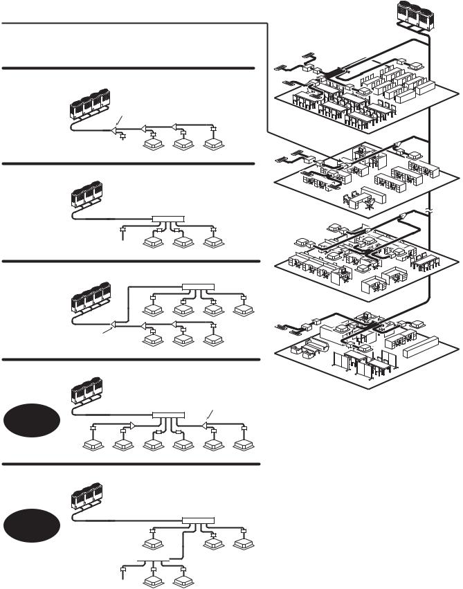
1.OUTLINE OF TOSHIBA SUPER HRM (Super Heat Recovery Multi System)
 Shortest route design by free branching
Combination of line and header branching is highly flexible.
This follows for the shortest design route possible, thereby saving on installation time and cost. Line/header branching after header branching is only available with TOSHIBA Super HRM.
Line branching
Outdoor unit
Branching joint
8F
FS unit
Indoor unit 
Header branching
Outdoor unit
Branching |
7F |
header
FS unit
Indoor unit 
Line + Header branching
Outdoor unit |
|
Header |
2F |
|
|
||
|
|
|
FS |
|
|
|
unit |
Branching joint |
Indoor |
|
|
unit |
|
|
|
|
|
|
|
Line branching after header branching |
1F |
||
Outdoor unit |
|
|
|
|
|
|
|
|
Header |
Branching joint |
|
Super HRM |
|
|
|
MMS Only |
|
|
|
Only |
FS unit |
|
|
Indoor unit |
|
Header branching after header branching
Outdoor unit
Header
Super HRM
Only
Header 
FS unit
Indoor unit
3

8F
7F
2F
1F
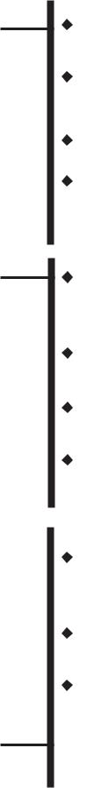
• Non-polarized control wiring between outdoor and indoor units
Outdoor unit |
U1 U2 |
|
|
Indoor unit |
U1 U2 |
U1 U2 |
U1 U2 |
Sub heat exchanger
main heat exchanger |
Outdoor unit |
|
FS unit |
|
|
|
|
|
Indoor |
|
|
|
|
|
unit |
|
|
|
Compressor |
|
Heating |
Cooling |
Cooling |
Cooling |
||
|
• Simultaneous operation
Allowable pipe length :
150m equivalent length
Outdoor  unit
unit 


differenceHeightbetween indoor outdoorandunitunit : 50m |
differenceHeightbetween indoor unitindoorandunit: 35m |
|
1st branching |
|
section |
From 1st branching to the farthest indoor unit : 50m
4
Energy saving
No. 1 COP in heat recovery VRF industry. Compared with the conventional chiller fan coil system, a large energy saving can be realized.
Advanced bus communication system
Wiring between indoor and outdoor unit is a simple 2 wire system.
Communication address is also automatically configured.
A default test mode operation is available.
Self diagnostics system
Comprehensive troubleshooting code allows for timely identification of problems arising.
High lift and flexible piping design
Equivalent pipe length of 150m and vertical lift of 50m is made possible with TOSHIBA Super HRM. Vertical lift between indoor units of 35m is the highest in the industry.
Also, maximum piping length from 1st branching is 50m. These allow for greater flexibility in the location of the system.
Simultaneous operation
By controling the FS unit, Super HRM enables freely simultaneous operation of cooling and heating. This operation meets the various needs of modern buildings that has highly airtight or an increasing heat load due to use of computers. Also, Super HRM improves energy efficiency by recycling exhaust heat.
Extended outdoor temperature operating range
By employing sophisticated system control with all inverter driven compressor, the operating range in cooling has been extended from -5ºC to -10ºC.
Compact FS unit design
The compact and light weight design of the FS unit (Flow selector unit) allows it to be easily installed in limited spaces.
Group control by one FS unit
Up to 8 indoor units of group control by one FS unit gives the design flexibility for various type and size of rooms.
Intelligent control
TOSHIBA Super HRM intelligent controls and modulating valves deliver the required capacity, according to the load variation from 50% to 100%.
The intelligent controls and modulating valves limit or increase the cooling capacity dynamically so humidity and temperature are kept in the comfort zone.
Conforms to building control law
IAQ (Indoor Air Quality) is also achieved by combining various accessories required by the Building Control Law.
Wide control applications
Artificial Intelligence Network system
•Central control and monitoring system available
•Weekly schedule operation through weekly timer
Integration with Building Management System (BMS) is available.
5
2. SUMMARY OF SYSTEM EQUIPMENTS
Equipments
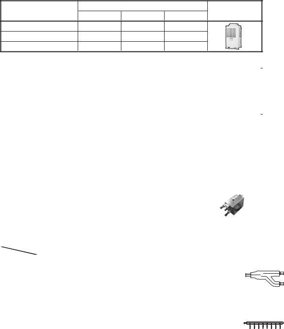
1. Outdoor units
Inverter unit
Corresponding HP |
|
|
Appearance |
|
|
|
8HP |
10HP |
12HP |
Model name |
MMY- |
MAP0802FT8 |
MAP1002FT8 |
MAP1202FT8 |
Cooling capacity (kW) |
|
22.4 |
28.0 |
33.5 |
Heating capacity (kW) |
|
25.0 |
31.5 |
35.5 |
2. Outdoor units (Combination of outdoor units)
Corresponding HP |
8HP |
10HP |
12HP |
16HP |
18HP |
|
Combined model |
MMY- |
MAP0802FT8 |
MAP1002FT8 |
MAP1202FT8 |
AP1602FT8 |
AP1802FT8 |
|
|
|
|
|
|
|
Cooling capacity (kW) |
|
22.4 |
28 |
33.5 |
45 |
50.4 |
Heating capacity (kW) |
|
25 |
31.5 |
35.5 |
50 |
56.5 |
|
|
8HP |
10HP |
12HP |
8HP |
10HP |
Combined outdoor units |
|
|
|
|
8HP |
8HP |
|
|
|
|
|
|
|
No. of connectable indoor units |
13 |
16 |
16 |
27 |
30 |
|
Corresponding HP |
20HP |
24HP |
26HP |
28HP |
30HP |
|
Combined model |
MMY- |
AP2002FT8 |
AP2402FT8 |
AP2602FT8 |
AP2802FT8 |
AP3002FT8 |
|
|
|
|
|
|
|
Cooling capacity (kW) |
|
56 |
68 |
73 |
78.5 |
84 |
Heating capacity (kW) |
|
63 |
76.5 |
81.5 |
88 |
95 |
|
|
10HP |
8HP |
10HP |
10HP |
10HP |
Combined outdoor units |
|
10HP |
8HP |
8HP |
10HP |
10HP |
|
|
|
8HP |
8HP |
8HP |
10HP |
No. of connectable indoor units |
33 |
40 |
43 |
47 |
48 |
|
3. FS units (Flow selector units)
Model name |
Usage |
|
Appearance |
|
|
|
|
RBM-Y1122FE |
Total capacity for indoor unit : |
Below 11.2 kw |
|
|
|
|
|
RBM-Y1802FE |
Total capacity for indoor unit : |
11.2 to below 18.0 kw |
|
|
|
|
|
RBM-Y2802FE |
Total capacity for indoor unit : |
18.0 to 28.0 kw or less |
|
|
|
|
|
* Accessory part (Sold separately): Connection cable kit (RBC-CBK15FE), up to 15m.
4. Branching joints and headers
|
Model name |
|
|
Usage |
|
|
|
|
Appearance |
|
|
|
|
|
|
|
|
|
|
|
RBM-BY53FE |
Indoor unit capacity code (*1) : Total below 6.4 |
|
|
|
|
|
||
|
RBM-BY103FE |
Indoor unit capacity code (*1) : Total 6.4 or more and below 14.2 |
|
|
For 3 |
|
|||
Y-shape |
RBM-BY203FE |
Indoor unit capacity code (*1) : Total 14.2 or more and below 25.2 |
|
|
piping |
|
|||
RBM-BY303FE |
Indoor unit capacity code (*1) : Total 25.2 or more |
|
|
|
|
|
|||
branching |
|
|
|
|
|
||||
RBM-BY53E |
Indoor unit capacity code (*1) : Total below 6.4 |
|
|
|
|
|
|||
joint (*3) |
|
|
|
|
|
||||
RBM-BY103E |
Indoor unit capacity code (*1) : Total 6.4 or more and below 14.2 |
|
|
For 2 |
|
||||
|
|
|
|
||||||
|
RBM-BY203E |
Indoor unit capacity code (*1) : Total 14.2 or more and below 25.2 |
|
piping (*6) |
|
||||
|
RBM-BY303E |
Indoor unit capacity code (*1) : Total 25.2 or more |
|
|
|
|
|
||
4-branching |
RBM-HY1043FE |
Indoor unit capacity code (*1) : Total below 14.2 |
|
|
|
For 3 |
|
||
RBM-HY2043FE |
Indoor unit capacity code (*1) : Total 14.2 or more and below 25.2 |
|
|
piping |
|
||||
header (*4) (*5) |
RBM-HY1043E |
Indoor unit capacity code (*1) : Total below 14.2 |
|
|
|
For 2 |
|
||
|
RBM-HY2043E |
Indoor unit capacity code (*1) : Total 14.2 or more and below 25.2 |
|
piping (*6) |
|
||||
8-branching |
RBM-HY1083FE |
Indoor unit capacity code (*1) : Total below 14.2 |
|
|
|
For 3 |
|
||
RBM-HY2083FE |
Indoor unit capacity code (*1) : Total 14.2 or more and below 25.2 |
|
|
piping |
|
||||
header (*4) (*5) |
RBM-HY1083E |
Indoor unit capacity code (*1) : Total below 14.2 |
|
|
|
For 2 |
|
||
|
RBM-HY2083E |
Indoor unit capacity code (*1) : Total 14.2 or more and below 25.2 |
|
piping (*6) |
|
||||
|
|
1 set 4 types T-shape joint pipes as described below: |
|
|
|
|
|
||
T-shape |
|
The required quantity is arranged and they are combined on site. |
|
|
|
||||
|
|
|
|
|
|
|
|
|
|
branching |
|
|
Connection piping |
Corresponded dia. (mm) |
Q'ty |
|
|
|
|
joint (For |
|
|
|
|
|
|
|
|
|
RBM-BT13FE |
|
Balance pipe |
Ø 9.5 |
1 |
|
|
|
|
|
connection |
|
|
|
|
|
||||
|
|
Piping at liquid side |
Ø12.7 to Ø22.2 |
1 |
|
|
|
|
|
of outdoor |
|
|
|
|
|
|
|||
|
|
Piping at discharge gas side |
Ø19.1 to Ø28.6 |
1 |
|
|
|
|
|
units) |
|
|
|
|
|
|
|||
|
|
Piping at suction gas side |
Ø22.2 to Ø38.1 |
1 |
|
|
|
|
|
|
|
|
|
|
|
|
|||
|
|
|
|
|
|
|
|
|
|
*1 “Capacity code” can be obtained from page 8. (Capacity code is not actual capacity)
*2 If total capacity code value of indoor unit exceeds that of outdoor unit, apply capacity code of outdoor unit. *3 When using Y-shape branching joint for 1st branching, select according to capacity code of outdoor unit. *4 Max. 6.0 capacity code in total can be connected.
*5 If capacity code of outdoor unit is 26 or more, it is not used for 1st branching. *6 This is used for branching to “cooling only” indoor unit.
*7 Model names for outdoor and indoor units described in this guide are shortened because of the space constraint.
6
50Hz
Super Heat Recovery Multi System Outdoor Unit
HP (Capacity |
Model name |
No. of |
Inverter |
Used |
Inverter |
Used |
Inverter |
Used |
|
combined |
8 HP |
10 HP |
12 HP |
||||||
code) |
MMY- |
Q'ty |
Q'ty |
Q'ty |
|||||
units |
MMY- |
MMY- |
MMY- |
||||||
|
|
|
|
|
|||||
|
|
|
|
|
|
|
|
|
|
8HP ( 8) |
MAP0802HT8 |
1 |
MAP0802FT8 |
1 |
|
|
|
|
|
|
|
|
|
|
|
|
|
|
|
10HP (10) |
MAP1002HT8 |
1 |
|
|
MAP1002FT8 |
1 |
|
|
|
|
|
|
|
|
|
|
|
|
|
12HP (12) |
MAP1202HT8 |
1 |
|
|
|
|
MAP1202FT8* |
1 |
|
|
|
|
|
|
|
|
|
|
|
16HP (16) |
|
2 |
MAP0802FT8 |
2 |
|
|
|
|
|
|
|
|
|
|
|
|
|
|
|
18HP (18) |
|
2 |
MAP0802FT8 |
1 |
MAP1002FT8 |
1 |
|
|
|
|
|
|
|
|
|
|
|
|
|
20HP (20) |
|
2 |
|
|
MAP1002FT8 |
2 |
|
|
|
|
|
|
|
|
|
|
|
|
|
24HP (24) |
|
|
MAP0802FT8 |
3 |
|
|
|
|
|
|
|
|
|
|
|
|
|
|
|
26HP (26) |
|
|
MAP0802FT8 |
2 |
MAP1002FT8 |
1 |
|
|
|
|
|
|
|
|
|
|
|
|
|
28HP (28) |
|
|
MAP0802FT8 |
1 |
MAP1002FT8 |
2 |
|
|
|
|
|
|
|
|
|
|
|
|
|
30HP (30) |
|
|
|
|
MAP1002FT8 |
3 |
|
|
|
|
|
|
|
|
|
|
|
|
*12HP unit is for stand-alone usage only.
Outdoor unit combination with 12HP unit is not available.
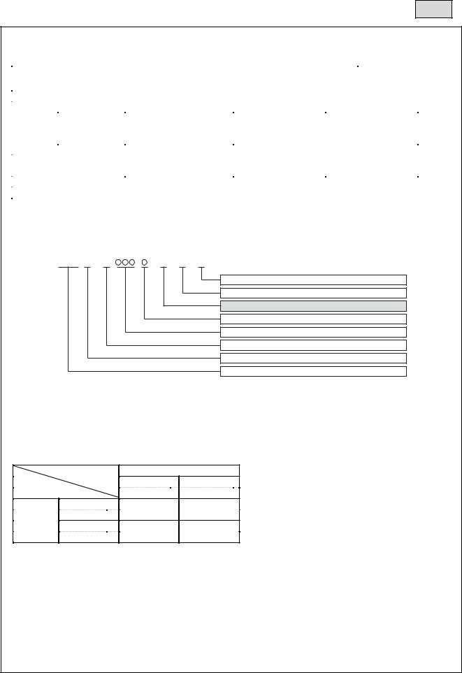
1.Allocation standard of model name
MMY– M AP |
F T 8 |
Power supply specifications, 3Ø 380–415 V, 50Hz ....... |
8 |
T : Capacity variable unit |
|
F : Heat recovery
Development series No.
Capacity rank HP x 10
New refrigerant R410A
M : Single module unit, No mark : Combined Model name
Modular Multi
2. Rated conditions (Rated mode : Condition)
Cooling : Indoor air temperature 27°C DB/19°C WB, Outdoor air temperature 35°C DB Heating : Indoor air temperature 20°C DB, Outdoor air temperature 7°C DB/6°C WB
3. Compatibility with 1 Series
Oudoor unit |
MMY- |
1 Series |
2 Series* |
-MAP**1FT8 |
-MAP**2FT8 |
1 Series |
NG |
OK |
|
RBM-Y***1E |
|
FS unit
2 Series
OK |
OK |
RBM-Y***2E
* 2 series outdoor units cannot be used with 1 series outdoor units.
7
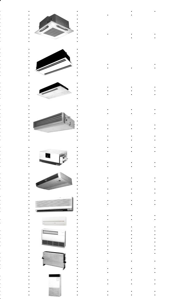
4. Indoor unit
*1) China only |
*2) European market only |
Type |
Appearance |
Model name |
Capacity rank |
Capacity code |
Cooling |
Heating |
capacity (kW) |
capacity (kW) |
|||||
|
|
MMU-AP0091H |
009 type |
1 |
2.8 |
3.2 |
|
|
MMU-AP0121H |
012 type |
1.25 |
3.6 |
4.0 |
|
|
MMU-AP0151H |
015 type |
1.7 |
4.5 |
|
|
|
5.0 |
||||
4-way Air Discharge |
|
MMU-AP0181H |
018 type |
2 |
5.6 |
6.3 |
|
MMU-AP0241H |
024 type |
2.5 |
7.1 |
8.0 |
|
Cassette Type |
|
MMU-AP0271H |
027 type |
3 |
8.0 |
9.0 |
|
|
MMU-AP0301H |
030 type |
3.2 |
9.0 |
10.0 |
|
|
MMU-AP0361H |
036 type |
4 |
11.2 |
12.5 |
|
|
MMU-AP0481H |
048 type |
5 |
14.0 |
16.0 |
|
|
MMU-AP0561H |
056 type |
6 |
16.0 |
18.0 |
|
|
MMU-AP0071WH |
007 type |
0.8 |
2.2 |
2.5 |
|
|
MMU-AP0091WH |
009 type |
1 |
2.8 |
3.2 |
|
|
MMU-AP0121WH |
012 type |
1.25 |
3.6 |
4.0 |
2-way Air Discharge |
|
MMU-AP0151WH |
015 type |
1.7 |
4.5 |
5.0 |
|
MMU-AP0181WH |
018 type |
2 |
5.6 |
6.3 |
|
Cassette Type |
|
|||||
|
MMU-AP0241WH |
024 type |
2.5 |
7.1 |
8.0 |
|
|
|
|||||
|
|
MMU-AP0271WH |
027 type |
3 |
8.0 |
|
|
|
9.0 |
||||
|
|
MMU-AP0301WH |
030 type |
3.2 |
9.0 |
10.0 |
|
|
MMU-AP0481WH*1) |
048 type |
5 |
14.0 |
16.0 |
|
|
MMU-AP0071YH |
007 type |
0.8 |
2.2 |
2.5 |
1-way Air Discharge |
|
MMU-AP0091YH |
009 type |
1 |
2.8 |
3.2 |
|
MMU-AP0121YH |
012 type |
1.25 |
3.6 |
4.0 |
|
Cassette Type |
|
MMU-AP0151SH |
015 type |
1.7 |
4.5 |
5.0 |
|
|
MMU-AP0181SH |
018 type |
2 |
5.6 |
6.3 |
|
|
MMU-AP0241SH |
024 type |
2.5 |
7.1 |
8.0 |
|
|
MMD-AP0071BH |
007 type |
0.8 |
2.2 |
2.5 |
|
|
MMD-AP0091BH |
009 type |
1 |
2.8 |
3.2 |
|
|
MMD-AP0121BH |
012 type |
1.25 |
3.6 |
|
|
|
4.0 |
||||
|
|
MMD-AP0151BH |
015 type |
1.7 |
4.5 |
|
|
|
5.0 |
||||
Concealed Duct |
|
MMD-AP0181BH |
018 type |
2 |
5.6 |
6.3 |
|
MMD-AP0241BH |
024 type |
2.5 |
7.1 |
8.0 |
|
Standard Type |
|
|||||
|
MMD-AP0271BH |
027 type |
3 |
8.0 |
9.0 |
|
|
|
|||||
|
|
MMD-AP0301BH |
030 type |
3.2 |
9.0 |
10.0 |
|
|
MMD-AP0361BH |
036 type |
4 |
11.2 |
12.5 |
|
|
MMD-AP0481BH |
048 type |
5 |
14.0 |
|
|
|
16.0 |
||||
|
|
MMD-AP0561BH |
056 type |
6 |
16.0 |
|
|
|
18.0 |
||||
|
|
MMD-AP0181H |
018 type |
2 |
5.6 |
6.3 |
|
|
MMD-AP0241H |
024 type |
2.5 |
7.1 |
8.0 |
Concealed Duct |
|
MMD-AP0271H |
027 type |
3 |
8.0 |
9.0 |
High Static |
|
MMD-AP0361H |
036 type |
4 |
11.2 |
12.5 |
Pressure Type |
|
MMD-AP0481H |
048 type |
5 |
14.0 |
16.0 |
|
|
MMD-AP0721H |
072 type |
8 |
22.4 |
|
|
|
25.0 |
||||
|
|
MMD-AP0961H |
096 type |
10 |
28.0 |
|
|
|
31.5 |
||||
|
|
MMC-AP0151H |
015 type |
1.7 |
4.5 |
5.0 |
|
|
MMC-AP0181H |
018 type |
2 |
5.6 |
6.3 |
Under Ceiling Type |
|
MMC-AP0241H |
024 type |
2.5 |
7.1 |
8.0 |
|
MMC-AP0271H |
027 type |
3 |
8.0 |
9.0 |
|
|
|
|||||
|
|
MMC-AP0361H |
036 type |
4 |
11.2 |
12.5 |
|
|
MMC-AP0481H |
048 type |
5 |
14.0 |
16.0 |
|
|
MMK-AP0071H |
007 type |
0.8 |
2.2 |
|
|
|
2.5 |
||||
High Wall Type |
|
MMK-AP0091H |
009 type |
1 |
2.8 |
3.2 |
|
MMK-AP0121H |
012 type |
1.25 |
3.6 |
4.0 |
|
(1 Series) |
|
MMK-AP0151H |
015 type |
1.7 |
4.5 |
5.0 |
|
|
MMK-AP0181H |
018 type |
2 |
5.6 |
6.3 |
|
|
MMK-AP0241H |
024 type |
2.5 |
7.1 |
8.0 |
High Wall Type |
|
MMK-AP0072H |
007 type |
0.8 |
2.2 |
2.5 |
|
MMK-AP0092H |
009 type |
1.0 |
2.8 |
3.2 |
|
(2 Series) *2) |
|
|||||
|
MMK-AP0122H |
012 type |
1.25 |
3.6 |
4.0 |
|
|
|
|||||
|
|
MML-AP0071H |
007 type |
0.8 |
2.2 |
|
|
|
2.5 |
||||
Floor Standing |
|
MML-AP0091H |
009 type |
1 |
2.8 |
3.2 |
|
MML-AP0121H |
012 type |
1.25 |
3.6 |
4.0 |
|
Cabinet Type |
|
MML-AP0151H |
015 type |
1.7 |
4.5 |
|
|
5.0 |
|||||
|
|
MML-AP0181H |
018 type |
2 |
5.6 |
|
|
|
6.3 |
||||
|
|
MML-AP0241H |
024 type |
2.5 |
7.1 |
8.0 |
|
|
MML-AP0071BH |
007 type |
0.8 |
2.2 |
2.5 |
|
|
MML-AP0091BH |
009 type |
1 |
2.8 |
|
Floor Standing |
|
3.2 |
||||
|
MML-AP0121BH |
012 type |
1.25 |
3.6 |
4.0 |
|
Concealed Type |
|
MML-AP0151BH |
015 type |
1.7 |
4.5 |
5.0 |
|
|
MML-AP0181BH |
018 type |
2 |
5.6 |
6.3 |
|
|
MML-AP0241BH |
024 type |
2.5 |
7.1 |
8.0 |
|
|
MMF-AP0151H |
015 type |
1.7 |
4.5 |
5.0 |
|
|
MMF-AP0181H |
018 type |
2 |
5.6 |
6.3 |
Floor Standing Type |
|
MMF-AP0241H |
024 type |
2.5 |
7.1 |
8.0 |
|
MMF-AP0271H |
027 type |
3 |
8.0 |
9.0 |
|
|
|
MMF-AP0361H |
036 type |
4 |
11.2 |
12.5 |
|
|
MMF-AP0481H |
048 type |
5 |
14.0 |
|
|
|
16.0 |
||||
|
|
MMF-AP0561H |
056 type |
6 |
16.0 |
18.0 |
8

5. Remote controller
Model Name name
Wired remote controller |
RBC-AMT21E |
Simple remote controller |
RBC-AS21E |
Wireless remote controller kit |
TCB-AX21U (W)-E |
RBC-AX22CE |
|
AX21E |
|
|
TCB- |
Appearance |
Application |
|
Function |
|
|
|
Connected to indoor unit |
• |
Start / Stop |
|
|
• |
Changing mode |
|
|
|
|
• |
Temperature setting |
|
|
|
• |
Air flow changing |
|
|
|
• |
Timer function |
|
|
|
|
Either “ON” time or “OFF” time or “CY- |
|
|
|
|
CLIC” can be set how many 30 min. later |
|
CODE No. |
|
|
ON or OFF is operated. |
|
|
|
Combined with the weekly timer, weekly |
|
SET DATA |
UNIT No. |
|
|
|
SETTINGTEST |
R.C. No. |
|
|
schedule operation can be operated. |
|
|
|
• |
Filter sign |
|
|
|
|
Displays automatically maintenance time of |
|
|
|
|
indoor filter. |
|
UNIT |
Wired remote Wired remote controller |
|
Filter sign flashes. |
|
|
• |
Self-diagnosis function |
|
SET CL |
|
controller (In case of control by |
||
|
|
2 remote controllers) |
|
Pressing “CHECK” button displays cause of |
|
|
|
|
trouble on the check code. |
|
|
|
• |
Control by 2 remote controllers is available. |
|
|
|
|
Two remote controllers can be connected to |
|
|
|
|
one indoor unit. The indoor unit can be |
|
|
|
|
separately operated from the isolated places. |
|
|
Connected to indoor unit |
• |
Start / Stop |
|
|
• |
Temperature setting |
|
|
|
|
• |
Air flow changing |
|
|
|
• |
Check code display |
TEST |
˚C |
|
|
|
SETTING |
˚F |
|
|
|
Simple remote controller
• Start / Stop
• Changing mode
• Temperature setting
• Air flow changing
• Timer function
Either “ON” time or “OFF” time or “CYCLIC” Connected to indoor unit can be set how many 30 min. later ON or OFF
is operated.
• Control by 2 remote controllers is available.
Two wireless remote controllers can operate one indoor unit. The indoor unit can be separately operated from the isolated places.
• Check code display
TCB-AX21U (W)-E
(For 4-way air discharge cassette)
RBC-AX22CE
(For under ceiling)
TCB-AX21E
(For others except concealed duct high static pressure)
9
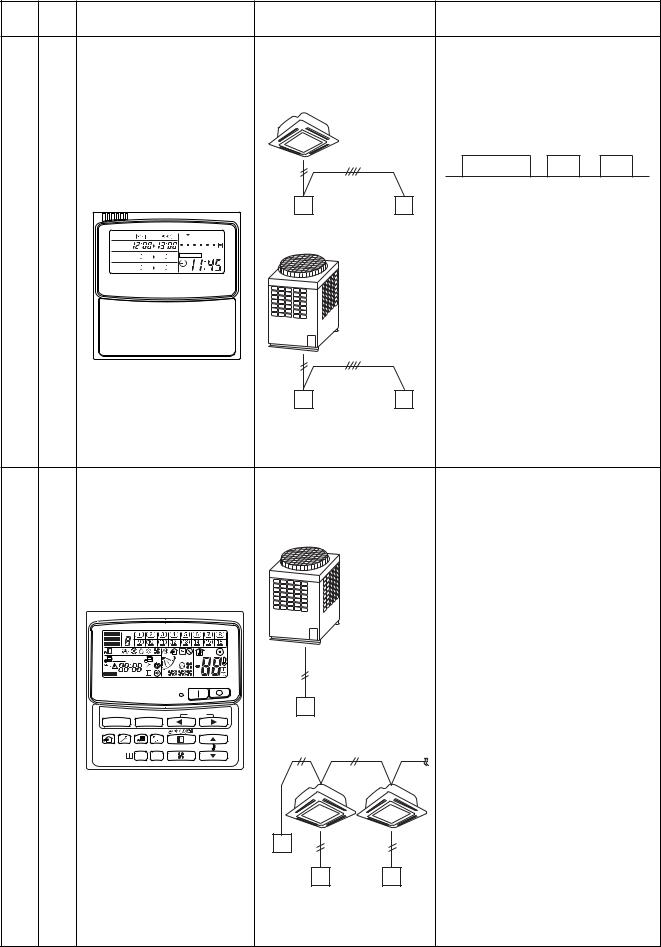
Model Name name
Weekly timer |
RBC-EXW21E |
Central remote controller |
TCB-SC642TLE |
|
Appearance |
Application |
|
|
Performance |
|
|
||||
|
|
|
|
|
• |
Weekly schedule operation |
|
|
|||
|
|
|
Connected to central |
|
Setting different start / stop time for |
||||||
|
|
|
remote controller, |
|
|||||||
|
|
|
|
each day of the week |
|
|
|||||
|
|
|
wired remote controller |
|
|
|
|||||
|
|
|
|
|
|
|
|
|
|||
|
|
|
|
|
|
|
ON / OFF can be easily set 3 times |
||||
|
|
|
|
|
|
|
a day. |
|
|
|
|
|
|
|
|
|
|
ON |
OFF ON |
OFF ON |
OFF |
||
|
|
|
|
|
|
8:00 |
12:00 |
13:00 |
18:00 |
19:00 |
21:00 |
|
|
|
Wired |
|
Weekly |
|
“CHECK” “PROGRAM” “DAY” |
||||
|
|
|
|
|
button make setting copy easy. |
||||||
|
|
|
remote controller |
|
timer |
|
|||||
|
|
SuMoTuWeTh Fr Sa |
|
|
|
|
|
|
|
||
|
|
|
|
|
|
Two patterns of schedule for a |
|||||
PROGRAM1 |
|
|
|
|
|
|
|||||
PROGRAM2 |
|
ERROR |
|
|
|
|
week can be specified. |
|
|
||
|
|
|
|
|
|
|
|
||||
PROGRAM3 |
|
|
|
|
|
|
|
|
|||
|
|
|
|
|
|
(Summer schedule and winter |
|||||
|
|
|
|
|
|
|
|||||
WEEKLY TIMER |
|
|
|
|
|
schedule, etc.) |
|
|
|
||
|
|
|
|
Outdoor unit |
|
“CANCEL” “DAY” button make |
|||||
|
|
|
|
|
|
|
|||||
|
|
|
|
|
|
|
holiday setting easy. |
|
|
||
|
|
|
|
|
|
|
If power supply fails, the setting |
||||
|
|
|
|
|
|
|
contents are stored in memory, for |
||||
|
|
|
|
|
|
|
100 hours. |
|
|
|
|
|
|
|
Central |
|
Weekly |
|
|
|
|
|
|
|
|
|
remote controller |
|
timer |
|
|
|
|
|
|
|
|
|
|
|
• |
Individual control up to 64 indoor units. |
|||||
|
|
|
Connected to outdoor unit, |
|
|
|
|
|
|
||
|
|
|
indoor unit |
• |
Individual control for max. 64 indoor |
||||||
|
|
|
|
|
|
units divided 1 to 4 zone. |
|
|
|||
|
|
|
Outdoor |
|
|
Up to 16 indoor units for each |
|||||
|
|
|
unit |
|
|
zone |
|
|
|
|
|
|
|
|
|
|
• |
Up to 16 outdoor header units are |
|||||
|
|
|
|
|
|
connectable. |
|
|
|
|
|
|
|
|
|
|
• |
4 type central control setting to inhibit |
|||||
|
|
|
|
|
|
individual operation by remote |
|
||||
ALL ZONE |
|
|
|
|
controller can be selected. |
|
|
||||
|
|
|
|
|
|
|
|
|
|
||
ZONE |
|
|
|
|
|
|
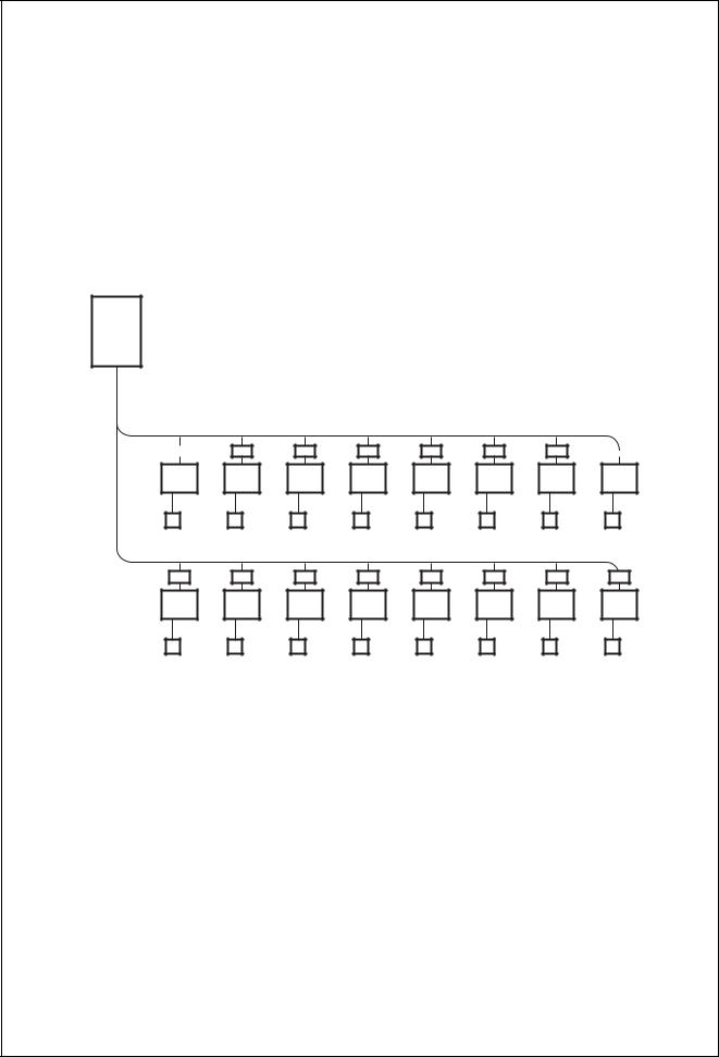
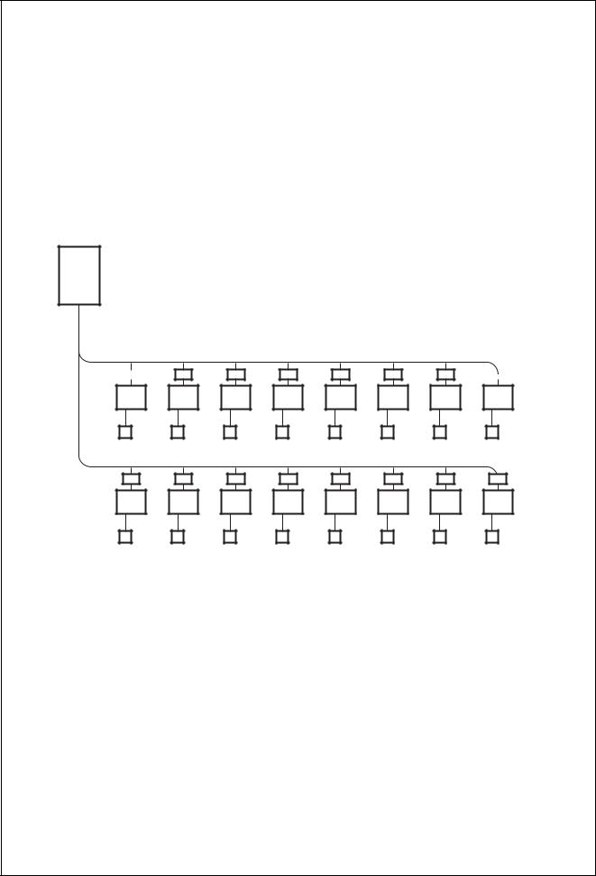
|
|
|
|
|
GROUP |
|
No. |
|
|
• |
Setting for one of 1 to 4 zone is |
|
||||
|
|
CODE |
|
|
|
|
|
|
|
|
|
1234 |
UNIT No. |
TEST |
|
|
|
available. |
|
|
|
|
|
SET DATA |
|
|
|
|
|
|
|
|
|
|
|
SETTING R.C. |
No. |
|
|
|
|
|
|
|
|
|
|
|
|
|
|
|
• |
Usable with other central control |
|
||||
|
|
|
|
|
|
devices (Up to 10 central control |
|
||||
|
|
GROUP |
|
|
|
devices in one control circuit) |
|
||||
SELECT |
ZONE |
Central |
|
|
|
|
|
|
|
|
|
|
|
|
|
• |
Two control mode selectivity |
|
|||||
|
|
|
remote controller |
|
|||||||
|
CL SET |
|
|
|
Central controller mode |
|
|||||
|
|
|
|
Remote controller mode |
|
||||||
|
|
|
|
|
|
|
|||||
|
|
|
|
|
• |
Setting of simultaneous ON/OFF 3 |
|||||
|
|
|
|
|
|
times for each day of the week |
|
||||
|
|
|
|
|
|
combined with weekly timer. |
|
||||
|
|
|
Central |
|
|
|
|
|
|
|
|
|
|
|
remote |
|
|
|
|
|
|
|
|
|
|
|
controller |
Indoor |
|
|
|
|
|
|
|
|
|
|
|
|
|
|
|
|
|
|
|
|
|
|
remote controller |
|
|
|
|
|
|
||
10
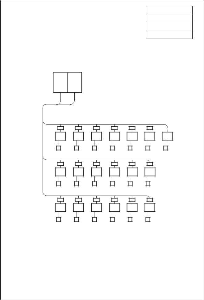
3. BASIC SYSTEM CONFIGURATION
8HP system |
|
|
Capacity code |
|
• Max. indoor unit : 13 units |
|
|
|
|
|
|
Total 10.4 |
||
• Capacity code of indoor unit : |
Min. : 5.6 |
|||
|
|
|||
No. of total units |
||||
|
|
Max. : 10.8 |
||
|
|
|
13 |
|
|
|
|
|
Outdoor unit
8HP |
Capacity code over the branch (0.8 + 0.8 = 1.6)
Indoor unit designation
10.4 |
4.8 |
4.0 |
3.2 |
2.4 |
1.6 |
|||||
|
|
|
|
|
|
|
|
|
|
|
|
|
|
|
|
|
|
|
|
|
|
007 |
007 |
007 |
007 |
007 |
(0.8) |
(0.8) |
(0.8) |
(0.8) |
(0.8) |
|||||
|
|
|
|
|
|
|
|
|
|
Capacity |
code |
007 |
(0.8) |
|
5.6 |
4.8 |
4.0 |
FS unit |
|
|
|
Indoor unit |
007 |
007 |
007 |
Remote |
(0.8) |
(0.8) |
(0.8) |
|||
|
|
|
|
|
|
|
controller |
|
|
|
|
|
|
|
|
|
|
|
|
|
3.22.4
007 |
007 |
(0.8) (0.8)
1.60.8
007 |
007 |
(0.8) (0.8)
11
10 HP system |
|
|
Capacity code |
|
• Max. indoor unit : 16 units |
|
|
Total 12.8 |
|
• Capacity code of indoor unit : |
Min. : 7 |
|||
|
||||
|
||||
|
|
Max. : 13.5 |
No. of total units |
|
|
|
|||
|
|
|
16 |
|
|
|
|
|
Outdoor unit
10HP |
12.8 |
6.4 |
5.6 |
4.8 |
4.0 |
3.2 |
2.4 |
1.6 |
|
|
|||||||
|
|
|
|
|
|
|
|
|
|
|
|
|
|
|
|
|
|
|
|
|
|
|
|
|
|
|
|
|
|
|
|
|
|
007 |
007 |
(0.8) |
(0.8) |
007 |
007 |
(0.8) |
(0.8) |
007 |
007 |
(0.8) |
(0.8) |
007 |
007 |
(0.8) |
(0.8) |
|
6.4 |
5.6 |
4.8 |
FS unit |
|
|
|
Indoor unit |
007 |
007 |
007 |
Remote |
(0.8) |
(0.8) |
(0.8) |
|||
|
|
|
|
|
|
|
controller |
|
|
|
|
|
|
|
|
|
|
|
|
|
4.0 3.2 2.4
007 |
007 |
007 |
(0.8) (0.8) (0.8)
1.6 |
|
007 |
007 |
(0.8) |
(0.8) |
12
12 HP system |
|
|
Capacity code |
|
• Max. indoor unit : 16 units |
|
|
Total 14.0 |
|
• Capacity code of indoor unit : |
Min. : 8.4 |
|||
|
||||
|
||||
|
|
Max. : 14.4 |
No. of total units |
|
|
|
|||
|
|
|
16 |
|
|
|
|
|
Outdoor unit
12HP |
14.0 |
6.4 |
5.6 |
4.8 |
4.0 |
3.2 |
2.4 |
1.6 |
|
|
|||||||
|
|
|
|
|
|
|
|
|
|
|
|
|
|
|
|
|
|
|
|
|
|
|
|
|
|
|
|
|
|
|
|
|
|
007 |
007 |
(0.8) (0.8)
007 |
007 |
(0.8) (0.8)
007 |
007 |
(0.8) (0.8)
007 |
007 |
(0.8) |
(0.8) |
|
|
|
|
|
|
|
|
7.6 |
6.8 |
6.0 |
5.0 |
||||
FS unit |
|
|
|
|
Indoor unit |
007 |
007 |
009 |
009 |
Remote |
(0.8) |
(0.8) |
(1.0) |
(1.0) |
||||
|
|
|
|
|
|
|
|
|
controller |
|
|
|
|
|
|
|
|
|
|
|
|
|
|
|
|
|
4.0 |
3.0 |
2.0 |
|
009 |
009 |
009 |
009 |
(1.0) |
(1.0) |
(1.0) |
(1.0) |
13
20 HP system
•Max. indoor unit : 33 units
•Capacity code of indoor unit : Min. : 14
Max. : 27
Outdoor unit
10HP 10HP
10
Capacity code
Total 26.75
No. of total units
19
26.75 |
10.25 |
8.25 |
6.25 |
5.0 |
3.75 |
2.5 |
|
|
||||||
|
|
|
|
|
|
|
|
|
|
|
|
|
|
|
|
|
|
|
|
|
|
|
|
|
|
|
|
|
|
018 |
018 |
(2.0) |
(2.0) |
012 |
012 |
012 |
012 |
012 |
(1.25) |
(1.25) |
(1.25) |
(1.25) |
(1.25) |
16.5 |
8.25 |
6.25 |
5.0 |
3.75 |
2.5 |
018 |
012 |
(2.0) |
(1.25) |
012 |
012 |
(1.25) |
(1.25) |
012 |
012 |
(1.25) |
(1.25) |
8.25 6.25 5.0 3.75 2.5 FS unit
Indoor unit |
018 |
Remote |
(2.0) |
controller |
|
012 |
012 |
(1.25) |
(1.25) |
012 |
012 |
012 |
(1.25) |
(1.25) |
(1.25) |
14
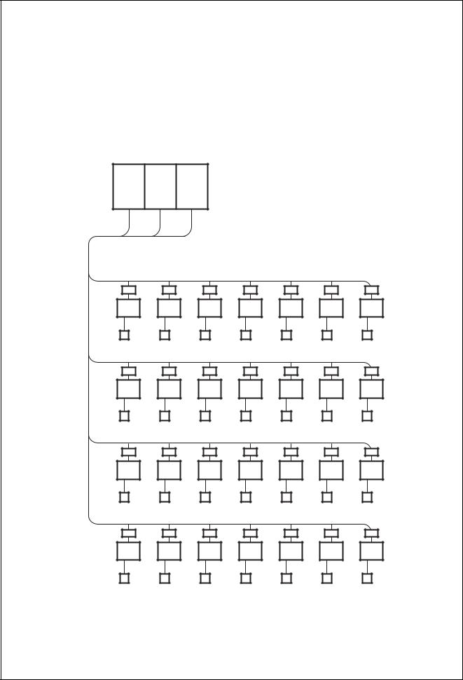
30 HP system |
|
|
Capacity code |
|
• Max. indoor unit : 48 units |
|
|
Total 40 |
|
• Capacity code of indoor unit : |
Min. : 21 |
|||
|
||||
|
No. of total units |
|||
|
Max. : 40.5 |
|||
|
|
|||
|
|
|
28 |
|
|
|
|
|
Outdoor unit
10HP 10HP 10HP
20 10
40 |
10 |
9.2 |
8.4 |
7.6 |
6.8 |
6 |
007 |
007 |
007 |
(0.8) (0.8) (0.8)
007 |
007 |
(0.8) (0.8)
018 |
036 |
(2) |
(4) |
30 |
10 |
9.2 |
8.4 |
7.6 |
6.8 |
6 |
007 |
007 |
007 |
(0.8) (0.8) (0.8)
007 |
007 |
(0.8) (0.8)
018 |
036 |
(2) |
(4) |
20 |
10 |
9.2 |
8.4 |
7.6 |
6.8 |
6 |
007 |
007 |
007 |
(0.8) (0.8) (0.8)
007 |
007 |
(0.8) (0.8)
018 |
036 |
(2) |
(4) |
|
10 |
9.2 |
FS unit |
|
|
Indoor unit |
007 |
007 |
Remote (0.8) (0.8) controller
8.4 7.6 6.8
007 |
007 |
007 |
(0.8) (0.8) (0.8)
6 |
|
018 |
036 |
(2) |
(4) |
15
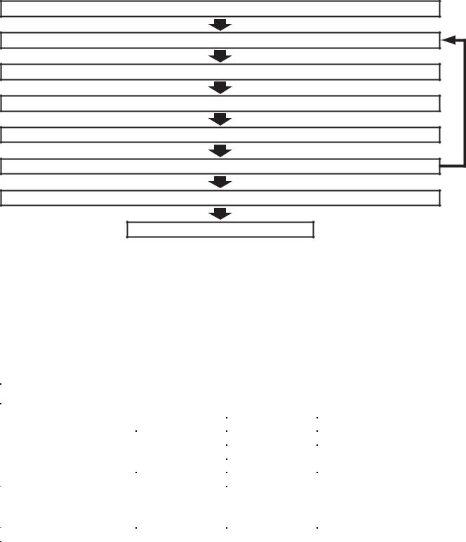
4. EQUIPMENT SELECTION PROCEDURE
1.Selection flow chart
1.Determination of indoor air conditioning load
2. Preliminary selection of indoor units
3.Preliminary selection of outdoor unit with indoor units
4.Capacity correction for piping length/height between indoor and outdoor units
5.Capacity correction based on indoor and outdoor temperature
NO
6.Validate preliminary selection of indoor units
7.Confirmation of selection for indoor unit and outdoor units
End
2. Combination conditions for indoor unit and outdoor unit
1. For indoor unit, the capacity code is decided for each capacity rank.
Capacity rank type |
007 |
009 |
012 |
015 |
018 |
024 |
027 |
030 |
036 |
048 |
056 |
072 |
096 |
|
|
|
|
|
|
|
|
|
|
|
|
|
|
Capacity code |
0.8 |
1 |
1.25 |
1.7 |
2 |
2.5 |
3 |
3.2 |
4 |
5 |
6 |
8 |
10 |
|
|
|
|
|
|
|
|
|
|
|
|
|
|
NOTE :
Capacity rank : Correspondence to Btu/h. Capacity code : Correspondence to Horsepower.
2. For outdoor unit, maximum No. of connectable indoor units and total capacity code of indoor units are decided.
Outdoor unit |
Capacity code of |
Max. No. of |
Total capacity code |
||
(Heat recovery) |
outdoor unit |
indoor units |
of indoor units |
||
MMY-MAP0802FT8 |
8 |
13 |
5.6 |
to |
10.8 |
|
|
|
|
|
|
MMY-MAP1002FT8 |
10 |
16 |
7.0 |
to |
13.5 |
|
|
|
|
|
|
MMY-MAP1202FT8 |
12 |
16 |
8.4 |
to |
14.4 |
|
|
|
|
|
|
MMY-AP1602FT8 |
16 |
27 |
11.2 |
to |
21.6 |
|
|
|
|
|
|
MMY-AP1802FT8 |
18 |
30 |
12.6 |
to |
24.3 |
|
|
|
|
|
|
MMY-AP2002FT8 |
20 |
33 |
14.0 |
to |
27.0 |
|
|
|
|
|
|
MMY-AP2402FT8 |
24 |
40 |
16.8 |
to |
32.4 |
|
|
|
|
|
|
MMY-AP2602FT8 |
26 |
43 |
18.2 |
to |
35.1 |
|
|
|
|
|
|
MMY-AP2802FT8 |
28 |
47 |
19.6 |
to |
37.8 |
|
|
|
|
|
|
MMY-AP3002FT8 |
30 |
48 |
21.0 |
to |
40.5 |
|
|
|
|
|
|
70 to 135% of outdoor unit capacity for all systems except 12HP  70 to 120% of outdoor unit capacity for 12HP
16

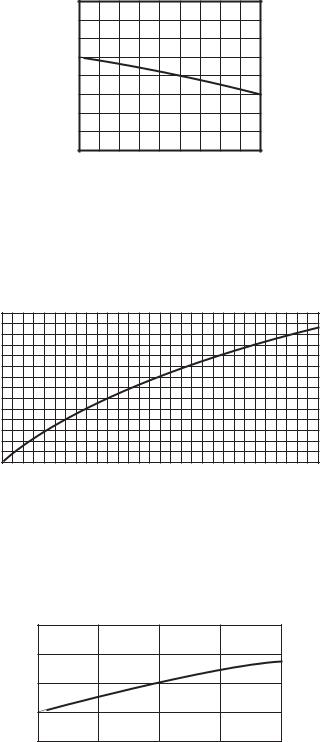
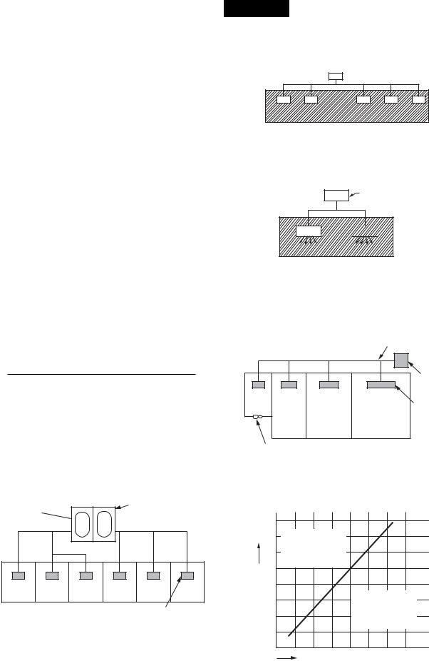
3. Cooling/heating capacity characteristics
1. Cooling capacity calculation method :
Required cooling capacity = Cooling capacity x Factor ( , , , , *1) kW
Indoor air wet bulb temperature vs. capacity correction value
Capacity correction value
1.2
1.1
1.0
0.9
0.8
15 |
20 |
24 |
Indoor air wet bulb temp. (˚C)
Outdoor air dry bulb temperature vs.capacity correction value
Capacity correction value
1.2
1.1
1.0
0.9
–5 |
0 |
5 |
10 |
15 |
20 |
25 |
30 |
35 |
40 43 |
Outdoor air dry bulb temp. (˚C)
Air flow variation ratio of indoor unit vs. capacity correction (For concealed duct type only)
Capacity correction value
1.1
1.0
0.9
80 |
90 |
100 |
110 |
120 |
Air flow variation ratio (%)
*1 : Coefficient to use for correction of outdoor unit capacity when total capacity of the indoor units are not equal to the outdoor unit capacity.
17
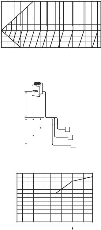
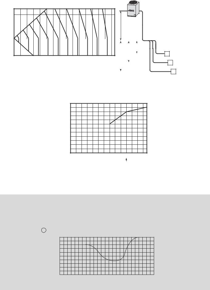
Connecting pipe length and lift difference between indoor and outdoor units vs. capacity correction value
Height of outdoor unit H (m)
50 Outdoor unit (8 to 30HP)
40
30 |
|
|
|
%100 |
|
||
20 |
|
||
|
|
|
|
|
|
|
|
10 |
|
|
|
|
|
|
|
|
|
|
|
0 |
98 |
96 |
94 |
92 |
90 |
88 |
86 |
84 |
82 |
80 |
78 |
76 |
|
|
|
|
|
|
|
|
|
|
|
|
–10
–20
–30 0 |
10 |
20 |
30 |
40 |
50 |
60 |
70 |
80 |
90 100 110 120 130 140 150 |
Pipe length (Equivalent length) L (m)
 Outdoor unit
L’ is the longest one of
(l’o + l’a, l’o + l’b, l’o + l’c)
ho l’o
H = ho +
(Largest one of ha, hb, and hc)
|
|
|
|
|
ha |
|
|
|
hc |
hb |
|
|
l’a A |
|
|
|
|
|
|
||||
|
|
|
|
l’b |
B Indoor unit |
||
|
|
|
|
|
|
||
|
|
|
|
|
|
||
|
|
|
|
|
|
l’c |
|
|
|
|
|
|
|
C |
|
|
|
|
|
|
|
||
|
|
|
|
|
|
|
|
Correction of outdoor unit diversity
Correction (%)
120
100
80
60
40
20
0 |
20 |
40 |
60 |
80 |
100 |
120 |
135 |
Standard capacity ratio
Indoor units total capacity ratio (%)
*1 : Coefficient to use for correction of outdoor unit capacity when total capacity of the indoor units are not equal to the outdoor unit capacity.
18
2. Heating capacity calculation method :
Required heating capacity = Heating capacity x Factor ( , , , , *1, *2) kW
Indoor air dry bulb temperature vs. capacity correction value
Capacity correction value
1.2
1.1
1.0
0.9
0.8
15 20 24
Indoor air dry bulb temp. (˚C)
Outdoor air wet bulb temperature vs. capacity correction value
Capacity correction value
1.2
1.1
1.0
0.9
0.8
0.7
0.6
0.5 –15 –10 –5 0 5 10 15
Outdoor air wet bulb temp. (˚C)
Air flow variation ratio of indoor unit vs. capacity correction (For concealed duct type only)
Capacity correction value
1.1
1.0
0.9 |
90 |
100 |
110 |
120 |
80 |
Air flow variation ratio (%)
*1 : Coefficient to use for correction of outdoor unit capacity when total capacity of the indoor units are not equal to the outdoor unit capacity.
*2 : Refer to item 3 in page 20.
19
Connecting pipe length and lift difference between indoor and outdoor units vs. capacity correction value
Height of outdoor unit H (m)
50 Outdoor unit (8 to 30HP)
40
30 |
|
|
|
|
|
|
|
|
|
|
|
|
|
|
|
|
|
|
|
|
|
|
|
|
|
|
|
100% |
|
|
|
|
|
|
|
|
|
|
|
|
|
|
|
|
|
|
|
|
|
|
|
|
|
10 |
|
|
|
|
|
|
|
|
|
|
|
|
|
|
|
|
|
|
|
|
|
|
|
|
|
|
20 |
|
|
|
|
|
|
|
|
|
|
|
|
|
|
|
|
|
|
|
|
|
|
|
|
|
|
0 |
|
|
|
|
|
|
|
|
|
|
|
|
|
|
|
|
|
|
|
|
|
|
|
|
|
|
|
|
|
|
|
|
|
|
|
|
|
|
|
|
|
|
|
|
|
|
|
|
|
|
|
|
|
|
|
|
|
99 |
|
|
98 |
|
|
97 |
|
|
96 |
|
95 |
|
|
94 |
93 |
92 |
91 |
|||||
–10 |
|
|
|
|
|
|
|
|
|
|
|
|
|
|||||||||||||
|
|
|
|
|
|
|
|
|
|
|
|
|
|
|
|
|
|
|
|
|
|
|
|
|
|
|
–20 |
|
|
|
|
|
|
|
|
|
|
|
|
|
|
|
|
|
|
|
|
|
|
|
|
|
|
|
|
|
|
|
|
|
|
|
|
|
|
|
|
|
|
|
|
|
|
|
|
|
|
|
|
|
–30 0 |
10 |
|
|
|
30 |
40 |
|
|
|
60 |
|
70 |
|
|
|
|
|
|
|
|
||||||
20 |
50 |
|
80 |
90 100 110 120 130 140 150 |
||||||||||||||||||||||
Pipe length (Equivalent length) L (m)
Correction of outdoor unit diversity
 Outdoor unit
L’ is the longest one of
(l’o + l’a, l’o + l’b, l’o + l’c)
ho l’o
H = ho +
(Largest one of ha, hb, and hc)
|
|
|
|
|
|
|
|
|
|
|
|
|
|
|
|
|
|
ha |
|
||
|
|
|
|
|
|
|
|
|||
|
hc |
hb |
|
|
|
l’a A |
|
|||
|
|
|
|
|
||||||
|
|
|
|
|
l’b |
B Indoor unit |
||||
|
|
|
|
|
|
|
|
|
||
|
|
|
|
|
|
|
|
|
||
|
|
|
|
|
|
|
|
|
l’c |
|
|
|
|
|
|
|
|
|
|
C |
|
|
|
|
|
|
|
|
|
|
||
|
|
|
|
|
|
|
|
|
|
|
Correction (%)
120
100
80
60
40
20
0 |
20 |
40 |
60 |
80 |
100 |
120 |
135 |
Standard capacity ratio
Indoor units total capacity ratio (%)
*1 : Coefficient to use for correction of outdoor unit capacity when total capacity of the indoor units are not equal to the outdoor unit capacity.
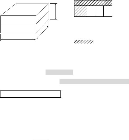
3. Capacity correction in case of frost on the outdoor heat exchanger in heating
Correct the heating capacity when frost was found on the outdoor heat exchanger.
Heating capacity = Capacity after correction of outdoor unit × Correction value of capacity resulted from frost (Capacity after correction of outdoor unit : Heating capacity calculated in the above item 2.)
6 Capacity correction in case of frost on the outdoor heat exchanger
Capacity correction value
1.0
0.9
0.8
–15
–10 |
–5 |
0 |
5 |
10 |
Outdoor air wet bulb temp. (˚C)
20
4. Capacity calculation for each indoor unit
Capacity for each indoor unit |
Required standard capacity of indoor unit |
||
= Capacity after correction of outdoor unit × |
|||
|
|
||
Total value of standard indoor unit capacity |
|||
|
|||
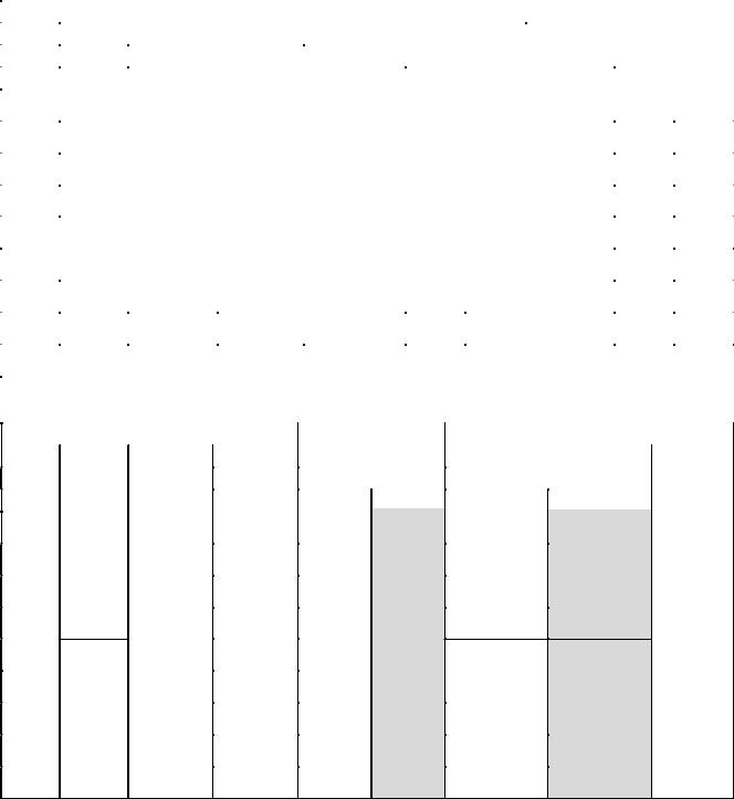
5. Operating temperature range
|
|
In cooling time |
|
|
||
|
45 |
|
|
|
|
|
(˚C) |
40 |
|
|
|
|
|
35 |
|
|
|
|
|
|
temp. |
|
|
|
|
|
|
30 |
|
|
|
|
|
|
|
|
|
|
|
|
|
dryairbulb |
25 |
|
|
Usablerange |
pull(indown) |
|
10 |
|
Continuously |
|
|||
|
20 |
|
|
|
|
|
|
|
|
operable |
|
|
|
Outdoor |
15 |
|
range |
|
|
|
5 |
|
|
|
|
|
|
|
|
|
|
|
|
|
|
0 |
|
|
|
|
|
|
–5 |
|
|
|
|
|
|
–10 |
15 |
20 |
25 |
28 |
30 |
|
10 |
|||||
Indoor air wet bulb temp. (˚C)
In heating time
|
20 |
|
|
|
|
|
(˚C) |
15 |
|
|
|
|
|
|
|
|
|
|
|
|
temp. |
10 |
|
|
|
|
|
5 |
|
|
|
|
|
|
Outdoor air wet bulb |
|
(in warming-up) |
|
|
|
|
0 |
Usable range |
Continuously |
|
|||
operable |
|
|||||
|
range |
|
|
|||
–5 |
|
|
|
|||
–10 |
|
|
|
|||
–15 |
|
|
|
|||
|
|
|
|
|
|
|
|
–20 |
10 |
15 |
20 |
25 |
30 |
|
5 |
|||||
Indoor air dry bulb temp. (˚C)
*The unit can be operated even if outdoor temperature gets down to -20°C, however note that the warranty covers only up to -15°C because operation beyond that temperature is out of specification.
*When outdoor air temperature falls to under -15°C, it may cause shortening the product lifetime.
*When outdoor temperature goes out of specified range “ or
or  ” mark is indicated on the remote controller display and required operation will stop.
“ &
&  ”: When heating operation “
 ”: When cooling operation
[Notice]
•This indication is not failure.
•When outdoor temperature goes back to specified range, “ or
or  ” disappear and start normal operation.
•Operation stops because concurrent operation can not be kept in the condition of out of specification for Super HRM.
(Outdoor temp.(DB) |
<-10°C: Cooling, |
|
>21°C: Heating) |
*Do not use “Super HRM” for other than personal usage where the ambient temperature may go down below -10°C. (For example, OA equipment/Electric device/Food/Animals and plants/Art object)
6.Rated conditions
Cooling :
Indoor air temperature 27°C DB/19.0°C WB, Outdoor air temperature 35°C DB
Heating :
Indoor air temperature 20°C DB, Outdoor air temperature 7°C DB/6°C WB
21
4. Example of equipment selection
The following shows an example of equipment selection based upon a building model
Fig. 1 Overview of building model
<Outside view> |
<Stories configuration> |
2F
1F
14.4m
8m
7.2m
2F |
|
|
|
Office rooms |
2 – 1 2 – 2 2 – 3 |
2 – 4 |
2 – 5 |
(2–1, 2–2 : Computer room) |
|
1 – 1 |
1 – 4 |
Stores |
|
1F |
|
|||
|
||||
|
1 – 3 |
(1-4 : Kitchen) |
||
1 – 2 |
||||
|
|
|||
|
|
|
||
|
|
|
|
|
|
|
Non-air conditioning zone |
||
|
|
|||
•Steel frame, reinforced concrete building, four stories above ground. Total floor area : 207m²
Outdoor unit is installed on the roof.
•Design indoor conditions
Cooling : 27.0/19.0°C DB/WB, Heating : 20°C DB
•Design outdoor conditions
Cooling : 35°C DB (Standard condition), Heating : 3°C WB (Standard condition : 6°C WB)
Selection Criteria for Each Floor
2F : Outdoor capacity exactly matches the total indoor capacity.
Total indoor HP = Outdoor unit HP Indoor : 2.5 HP x 2 units + 1.25 HP + 2 HP x 2 = 10.25 HP Outdoor : 10 HP Same capacity
Heat load of room 2-1 and 2-2 is higher than other rooms.
1F : Consider the increasing heat load in the specific room.
•Total indoor units HP > Outdoor unit HP
•Select each indoor unit based on individual peak room load. Indoor : 2.5HP + 2.5HP + 3.2HP + 2.0HP =
10.2HP < > Outdoor : 10HP (Same capacity)
•The room “1-4” is designed for “cooling only” because of its high heat load.
•The outdoor module should have sufficient capacity to cover the peak demand of the indoor unit connected.
22
Procedure and result of equipment selection
1.Procedure of equipment selection
a.Calculate cooling for every rooms.
b.Select an indoor unit to match the cooling load for every room from the table in pages 8.
c.Choose a tentative outdoor module that will match with the indoor units. Perform capacity correction based on the pipe length, system lift, indoor set temperature, outdoor temperature.
Then, make sure the corrected system cooling capacity satisfies the cooling load.
2.Equipment selection and capacity check
|
Air conditioning load |
|
|
|
Equipment selection |
|
|
||||
|
|
|
|
|
|
|
|
|
|
|
|
|
|
Indoor air conditioning load |
Indoor unit |
|
|
Outdoor unit |
|
||||
Floor |
Room No. |
(kW) |
|
Model |
Capacity (kW) |
Model |
Capacity (kW) |
||||
|
|
|
|||||||||
|
|
|
|
|
|
|
|
MMY- |
|
|
|
|
|
Cooling |
|
Heating |
Cooling |
|
Heating |
Cooling |
Heating |
||
|
|
|
|
|
|||||||
|
|
|
|
|
|
|
|
|
|
|
|
|
2-1 |
6.0 |
|
3.4 |
MMU-AP0241H |
7.1 |
|
8.0 |
|
|
|
|
|
|
|
|
|
|
|
|
|
|
|
|
2-2 |
5.0 |
|
2.2 |
MMU-AP0181H |
5.6 |
|
6.3 |
|
|
|
2F |
|
|
|
|
|
|
|
|
|
|
|
2-3 |
5.0 |
|
4.2 |
MMU-AP0181H |
5.6 |
|
6.3 |
|
|
|
|
|
|
|
|
|
|
|
|
|
|
|
|
|
2-4 |
3.2 |
|
2.7 |
MMU-AP0121H |
3.6 |
|
4.0 |
|
|
|
|
|
|
|
|
|
|
|
|
MAP2002FT8 |
56.0 |
63.0 |
|
2-5 |
6.4 |
|
5.4 |
MMU-AP0241H |
7.1 |
|
8.0 |
|||
|
|
|
|
|
|
|
|
|
|
|
|
|
1-1 |
6.1 |
|
6.0 |
MMU-AP0241H |
7.1 |
|
8.0 |
|
|
|
|
|
|
|
|
|
|
|
|
|
|
|
|
1-2 |
6.3 |
|
6.3 |
MMU-AP0241H |
7.1 |
|
8.0 |
|
|
|
1F |
|
|
|
|
|
|
|
|
|
|
|
1-3 |
7.2 |
|
7.0 |
MMU-AP0301H |
9.0 |
|
10.0 |
|
|
|
|
|
|
|
|
|
|
||||||
|
|
|
|
|
|
|
|
|
|
|
|
|
1-4 |
5.1 |
|
— |
MMD-AP0181H |
5.6 |
|
6.3 |
|
|
|
|
|
|
|
|
|
|
|
|
|
|
|
|
Piping distance |
|
Capacity correction |
Capacity check after correction |
|||||
|
|
|
|
|
|
|
|
|
|
|
|
|
Height |
Pipe correction x temp. |
|
Capacity |
|
||
|
|
Equivalent |
|
|
|
||||
|
|
correction |
|
|
|
||||
Floor |
Room No. |
difference |
Capacity (kW) |
Judgment |
|||||
length (m) |
|
|
|||||||
|
|
(m) |
|
|
|
|
|
||
|
|
|
Cooling |
Heating |
Cooling |
Heating |
|
||
|
|
|
|
|
|||||
|
|
|
|
|
|
|
|
|
|
|
2-1 |
|
|
|
|
6.6 |
7.0 |
|
|
|
|
|
|
|
|
|
|
|
|
|
2-2 |
|
|
|
|
5.2 |
5.5 |
|
|
2F |
|
|
|
|
|
|
|
|
|
2-3 |
|
|
|
1.0 |
5.2 |
5.5 |
|
||
|
|
|
|
|
|
|
|
||
|
2-4 |
|
|
1.0 |
× |
3.3 |
3.5 |
|
|
|
|
|
× |
0.95 |
|
||||
|
|
|
|
|
|
|
|||
1.0×
2-5 |
34 |
5 |
× |
0.98 |
6.6 |
7.0 |
good |
|
|
|
|
|
0.936 |
× |
|
|
|
1-1 |
|
|
= |
0.95 |
6.6 |
7.0 |
|
|
|
|
0.936 |
= |
|
||||
|
|
|
|
|
|
|
||
|
|
|
|
|
0.884 |
|
|
|
1-2 |
|
|
|
6.6 |
7.0 |
|
||
|
|
|
|
|
||||
1F |
|
|
|
|
|
|
|
|
|
|
|
|
|
|
|
|
|
1-3 |
|
|
|
|
8.4 |
8.8 |
|
|
|
|
|
|
|
|
|
|
|
1-4 |
|
|
|
|
5.2 |
5.5 |
|
|
23
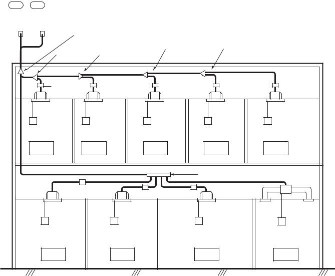
Schematic diagram
MMY-MAP2002FT8
10 10
|
|
|
|
|
|
|
|
|
|
|
|
|
|
|
Outdoor unit |
|
|
|
|
|
|
|
|
|
|
|
|
|
|
|
|
|
|
|
|
|
|
|
|
|
|
|
|
|
|
|
|
|
|
|
|
|
|
|
|
|
|
|
|
|
|
|
|
|
|
|
|
|
1st branching joint |
4th branching |
5th branching |
|
|
|
|
|
|
|
|
||||||||||
|
|
|
|
|
|
|
|
|
|
|
|
|
|
|
3rd branching |
||
|
|
|
|
|
|
|
|
|
|
|
|
|
|
|
2nd branching joint |
joint |
joint |
|
|
|
|
|
|
|
|
|
|
|
|
|
|
|
joint |
|
|
FS unit |
|
FS unit |
FS unit |
FS unit |
FS unit |
RBM-Y1122FE |
RBM-Y1122FE |
RBM-Y1122FE |
RBM-Y1122FE |
RBM-Y1122FE |
|
Indoor unit |
|
Indoor unit |
Indoor unit |
Indoor unit |
Indoor unit |
MMU-AP0241H |
|
MMU-AP0181H |
MMU-AP0181H |
MMU-AP0121H |
MMU-AP0241H |
R |
R |
R |
R |
R |
|
Computer |
Computer |
Office |
Office |
Office |
|
Room |
|
Room |
|||
|
|
|
|
||
2 – 1 |
|
2 – 2 |
2 – 3 |
2 – 4 |
2 – 5 |
|
|
|
|
Branching header |
|
FS unit |
FS unit |
FS unit |
|
||
RBM-Y1122FE |
|
||||
RBM-Y1122FE |
RBM-Y1122FE |
|
|||
|
|
|
|
||
Indoor unit |
|
Indoor unit |
Indoor unit |
Indoor unit |
|
MMU-AP0241H |
|
MMU-AP0241H |
MMU-AP0301H |
MMD-AP0181H |
|
R |
|
R |
|
R |
R |
|
|
|
|
|
<Cooling only> |
Store |
|
Store |
|
Restaurant |
Kitchen |
1 – 1 |
|
|
1 – 2 |
1 – 3 |
1 – 4 |
24
5. REFRIGERANT PIPING DESIGN
1. Warnings on refrigerant leakage Important
Check of Concentration Limit
The room in which the air conditioner is to be installed requires a design that in the event of refrigerant gas leaking out, its concentration will not exceed a set limit.
The refrigerant R410A which is used in the air conditioner is safe, without the toxicity or combustibility of ammonia, and is not restricted by laws to be imposed which protect the ozone layer. However, since it contains more than air, it poses the risk of suffocation if its concentration should rise excessively. Suffocation from leakage of R410A is almost non-existent. With the recent increase in the number of high concentration buildings, however, the installation of multi air conditioner systems is on the increase because of the need for effective use of floor space, individual control, energy conservation by curtailing heat and carrying power etc.
Most importantly, the multi air conditioner system is able to replenish a large amount of refrigerant compared with conventional individual air conditioners. If a single unit of the multi conditioner system is to be installed in a small room, select a suitable model and installation procedure so that if the refrigerant accidentally leaks out, its concentration does not reach the limit (and in the event of an emergency, measures can be made before injury can occur).
In a room where the concentration may exceed the limit, create an opening with adjacent rooms, or install mechanical ventilation combined with a gas leak detection device.
The concentration is as given below.
Total amount of refrigerant (kg)
Min. volume of the indoor unit installed room (m³)
≤ Concentration limit (kg/m³)
The concentration limit of R410A which is used in multi air conditioners is 0.3kg/m³.
(For details, refer and comply with local regulations.)
NOTE 1 :
If there are 2 or more refrigerating systems in a single refrigerating device, the amounts of refrigerant should be as charged in each independent device.
Outdoor unit
e.g., charged
amount (10kg) 
 e.g.,
e.g.,
charged amount (15kg)
Room A Room B Room C Room D Room E Room F
Indoor unit
For the amount of charge in this example:
The possible amount of leaked refrigerant gas in rooms A, B and C is 10kg.
The possible amount of leaked refrigerant gas in rooms D, E and F is 15kg.
NOTE 2 :
The standards for minimum room volume are as follows.
(1) No partition (shaded portion)
(2)When there is an effective opening with the adjacent room for ventilation of leaking refrigerant gas (opening without a door, or an opening 0.15% or larger than the respective floor spaces at the top or bottom of the door).
Outdoor unit
 Refrigerant piping

 Indoor unit
(3)If an indoor unit is installed in each partitioned room and the refrigerant tubing is interconnected, the smallest room of course becomes the object. But when a mechanical ventilation is installed interlocked with a gas leakage detector in the smallest room where the density limit is exceeded, the volume of the next smallest room becomes the object.
|
|
Refrigerant piping |
|
|
|
Outdoor unit |
|
Very |
|
|
|
small |
|
Indoor unit |
|
room |
|
||
Small |
Medium |
Large room |
|
room |
room |
||
|
Mechanical ventilation device - Gas leak detector
NOTE 3 :
The minimum indoor floor area compared with the amount of refrigerant is roughly as follows: (When the ceiling is 2.7m high)
|
40 |
|
|
|
|
m² 35 |
Range below the |
|
|
|
|
density limit |
|
|
|
||
|
30 |
of 0.3 kg/m³ |
|
|
|
|
(countermeasures |
|
|
|
|
|
|
|
|
|
|
|
25 |
not needed) |
|
|
|
area |
|
|
|
|
|
20 |
|
|
|
|
|
floor |
15 |
|
Range above |
|
|
|
the density limit |
|
|||
indoor |
10 |
|
of 0.3 kg/m³ |
|
|
|
(countermeasures |
|
|||
|
|
needed) |
|
|
|
Min. |
5 |
|
|
|
|
|
|
|
|
||
0 |
|
|
|
|
|
|
10 |
20 |
30 |
|
|
|
|
|
|||
|
|
Total amount of refrigerant |
kg |
||
25
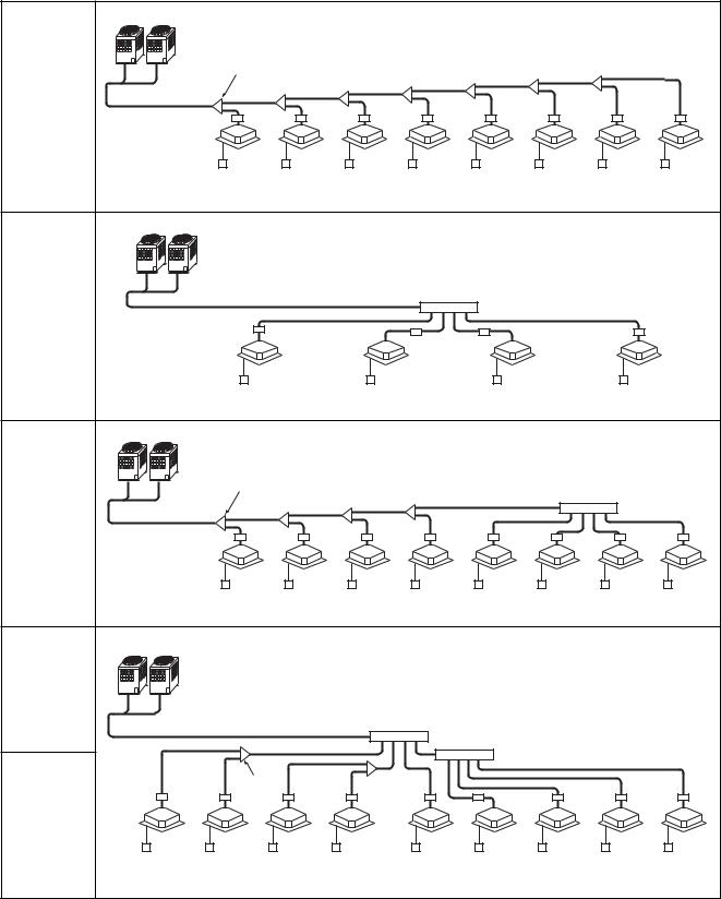
2. Free branching system
Line branching system
Header branching system
Header branching system after line branching
Line branching system after header branching
Header branching system after header branching
The above five branching systems are available to dramatically increase the flexibility of refrigerant piping design.
|
|
Outdoor unit |
|
|
Branching joint |
Line |
|
|
branching |
|
|
system |
|
FS unit |
|
|
|
|
|
Indoor unit |
|
|
Remote |
|
|
controller |
|
|
Outdoor unit |
Header |
|
Branching header |
|
|
|
branching |
|
|
system |
|
FS unit |
|
|
Indoor unit |
|
|
Remote controller |
|
|
Outdoor unit |
Header |
|
Branching joint |
|
Branching header |
|
branching |
|
|
system |
|
|
after line |
|
FS unit |
branching |
|
Indoor unit |
|
|
|
|
|
Remote |
|
|
controller |
Line |
|
|
branching |
|
Outdoor unit |
system after |
|
|
header |
|
|
branching |
|
Branching header |
|
|
|
|
|
Branching |
Header |
FS unit |
joint |
|
||
branching |
Indoor |
|
system after |
unit |
|
header |
|
Remote |
branching |
|
controller |
|
|
26 |

3. Allowable length/height difference of refrigerant piping
Height difference between outdoor units
H3 5m
5m
Height difference between outdoor and indoor units
H1 50m
50m
|
|
|
|
|
|
|
|
|
|
|
|
|
|
|
|
|
|
|
|
|
|
Follower Unit |
||||||||||
|
|
|
|
|
|
|
|
|
|
|
|
|
|
|
|
|
|
|
|
|
|
|
|
|
|
|
C |
|||||
|
|
|
|
|
|
|
|
|
|
|
|
|
|
|
|
|
|
|
|
|
|
|
|
|
|
|
|
|
|
|||
|
|
|
|
|
|
|
|
|
|
|
|
|
|
|
|
|
|
|
|
|
|
|
|
|
|
|
|
|
|
|
|
|
|
|
|
|
|
|
|
|
|
|
|
|
|
|
|
|
|
|
|
|
|
|
|
|
|
|
|
|
|
|
|
|
|
|
|
|
|
|
|
|
|
|
|
|
|
|
|
|
|
|
|
|
|
|
|
|
|
|
|
|
|
|
|
|
|
|
Header Unit Follower Unit |
|
|
|
|
|
|
|
|
|
|
|
|||||||||||||||||||||
|
|
|
|
|
A |
|
|
|
|
|
|
|
|
B |
|
|
|
|
|
|
|
|
|
|
|
|||||||
Outdoor Unit |
|
|
|
|
|
|
|
|
|
|
|
|
|
|
|
|
|
|
|
|
|
|
|
|
|
|
|
|
|
|
|
|
|
|
|
|
|
|
|
|
|
|
|
|
|
|
|
|
|
|
|
|
|
|
|
|
|
|
|
|
|
|
|
|
|
T-shape |
|
La |
|
|
|
|
|
|
|
|
|
Lb |
|
|
|
|
|
|
|
|
|
|
Lc |
|||||||||
branching |
|
|
|
|
|
|
|
|
|
|
|
|
|
|
|
|
|
|
|
|
|
|
|
|
|
|||||||
Main piping |
|
|
|
|
LA |
|
|
|
|
|
|
|
|
|
|
|
|
|
|
|
||||||||||||
|
|
|
|
|
|
|
|
|
|
|
|
|
|
|
|
|
|
|
|
|
|
|
|
|
|
|
|
|
|
|
|
|
Note:
In case of connecting method <Ex.2>, a large amount of refrigerant and refrigerant oil may return to the head unit. Therefore, set the T-shape joint so that oil does not enter directly.
<Ex.1> Header Unit Follower Unit Follower Unit
A B C
|
Main connecting piping between outdoor units |
<Ex.2> Header Unit Follower Unit Follower Unit |
||||||||||||||||||||||||||||||||||||
|
Length corresponded to farthest piping |
|||||||||||||||||||||||||||||||||||||
|
|
|
|
|
|
A |
|
|
|
|
|
|
B |
|
|
|
|
|
|
C |
||||||||||||||||||
|
between outdoor units LO 25m |
|
|
|
|
|
|
|
|
|
|
|
|
|
|
|
|
|
||||||||||||||||||||
|
|
|
|
|
|
|
|
|
|
|
|
|
|
|
|
|
|
|
|
|
|
|
|
|
|
|
|
|
|
|
|
|
|
|
|
|
|
|
|
|
|
|
|
|
|
|
|
|
|
|
|
|
|
|
|
|
|
|
|
|
|
|
|
|
|
|
|
|
|
|
|
|
|
|
|
|
|
L1 |
|
|
|
|
|
|
|
|
|
|
|
|
|
|
|
|
|
|
|
|
|
|
|
|
|
|
|
|
|
|
|
|
|
|
|
|
|
|
|
Branching |
|
|
|
|
|
|
|
|
|
|
|
|
|
|
|
|
|
|
|
|
|
|
|
|
|
|
|
|
|
|
|
|
|
|
|
|
|
|
Branching piping L2 header |
|
|
|
|
|
|
|
|
|
|
|
|
|
|
|
|
|
|
|
|
|
|
|
|
|
|
|
|
|
|
|
|
|
|
|
|
|
1st branching section
L3
|
|
|
Connecting piping of |
|
|
|
|
|
|
|
|
|
|
|
|
|
|
|
|
|
|
|
|
|
|
|
|
|
|
|
|
|
|
|
|
|
|
|
|
|
|
|
|
|
||||||||||||
|
|
|
indoor unit |
|
|
|
|
|
|
|
|
|
|
|
|
|
L9 |
|
|
|
|
|
|
|
|
|
|
|
|
|
|
|
|
|
|
|
|
|
|
|
|
|
|
|
|
|||||||||||
|
|
|
|
|
|
|
a |
|
|
|
|
|
|
|
|
|
|
|
|
|
|
|
|
|
|
|
|
|
|
|
|
|
|
|
|
|
|
|
|
|
|
|
|
|
|
|
|
|
|
|
|
|
||||
|
|
|
|
|
|
|
|
|
|
b |
|
|
|
|
|
c |
|
|
|
|
|
|
|
|
|
|
|
|
|
|
|
|
|
|
|
|
|
|
|
|
|
|
|
|
|
|
|
|
|
|||||||
|
|
|
|
|
|
|
|
|
|
|
|
|
|
|
|
|
|
|
|
|
|
|
|
FS unit |
|
|
|
|
|
|
|
|
|
|
|
|
|
|
|
|
|
|
|
|
|
|
|
|
|
|
|
|
||||
|
|
|
|
|
|
|
|
|
|
|
|
|
|
|
|
|
|
|
|
|
|
|
|
|
|
|
|
|
|
|
|
|
|
|
|
|
|
|
|
|
|
|
|
|
|
|
|
|
|
|
|
|||||
|
|
|
g |
|
|
|
|
|
h |
|
|
|
i |
|
|
|
|
|
|
|
|
j |
|
|
|
|
k |
|
|
|
|
|
|
|
|
|
|
|
|
|
|
|
|
|
|
|
|
|
|
|||||||
|
|
|
|
|
|
|
|
|
|
|
|
|
|
|
|
|
|
|
|
|
|
|
|
|
|
|
|
|
|
|
|
|
|
|
|
|
|
|
|
|
|
|||||||||||||||
|
|
|
|
|
|
Indoor unit |
|
|
|
|
|
|
|
|
|
|
|
< Cooling only > < Cooling only > |
||||||||||||||||||||||||||||||||||||||
|
|
|
|
|
|
|
Equivalent length corresponded to farthest piping L 150m |
|
|
|
|
|
|
|
|
|
|
|
|
|
|
|||||||||||||||||||||||||||||||||||
|
Equivalent length corresponded to farthest piping after 1st branching Li |
|
|
50m |
|
|||||||||||||||||||||||||||||||||||||||||||||||||||
|
|
|
|
|
|
|
|
|
|
|
|
|
|
|
|
|
|
|
|
|
|
|
|
|
|
|
|
|
|
|
|
|
|
Lj |
|
|
|
|
|
|
|
|
|
|
|
|
|
|
|
|
|
Height difference |
||||
|
|
|
|
|
|
|
|
|
|
|
|
|
|
|
|
|
|
|
|
|
|
|
|
|
|
|
|
|
|
|
|
|
|
|
|
|
|
|
|
|
|
|
|
|
|
|
|
|
|
|
between |
|||||
|
|
|
|
|
|
|
|
L4 |
|
|
|
L5 |
|
|
L6 |
|
L7 |
|
L8 |
|
|
|
|
|
|
|
|
|
|
|
|
|
|
|
|
|
indoor |
|||||||||||||||||||
|
|
|
|
|
|
|
|
|
|
|
|
|
|
|
|
|
|
|
|
|
|
|
|
|
|
|
|
|
|
|
|
units |
||||||||||||||||||||||||
|
|
|
|
|
|
|
|
|
|
|
|
|
|
|
|
|
|
|
|
|
|
|
|
|
|
|
|
|
|
|
|
|
|
|
|
|
|
|
|
|
|
|
|
|
|
|
|
|
|
|
|
|
||||
|
|
|
|
|
|
|
|
|
|
|
|
|
|
|
|
|
|
|
|
|
FS |
unit |
|
|
|
|
|
|
|
|
|
|
|
|
|
|
|
|
|
|
|
|
|
|
|
|
H2 35m |
|||||||||
|
|
|
|
|
|
d |
|
|
|
e |
|
|
|
|
|
f |
|
|
Lh |
o |
|
|
|
|
|
|
|
|
|
|
|
|
|
|
|
|
|
|
|
|
|
|
|
|||||||||||||
FS unit |
|
|
|
|
|
|
|
|
|
|
|
|
|
|
|
|
|
|
|
|
|
|
|
|
|
|
|
|
|
|
|
|
|
|
|
|
|
|
|
|
|
|
|
|
|
|
|
|
|
(Upper outdoor unit) |
||||||
|
|
|
l |
|
|
|
|
|
|
m |
|
|
|
|
n |
|
|
|
|
|
|
|
|
|
|
|
|
|
|
|
|
|
|
|
|
|
|
|
|
|
|
|
|
|
|
|
|
|
|
|
||||||
|
|
|
|
|
|
|
|
|
|
|
|
|
|
|
|
|
|
|
|
|
|
|
|
|
|
|
|
|
|
|
|
|
|
|
|
|
|
|
|
|
|
|||||||||||||||
|
|
|
|
Indoor unit |
|
|
|
|
|
|
|
|
|
|
|
|
|
|
|
|
|
|
|
|
|
|
|
|
|
|
|
|
|
|
|
|
|
|
|
|
|
|
|
|
|
|||||||||||
|
|
|
|
|
|
|
|
|
|
|
|
|
|
|
(Header) |
|
|
|
|
|
|
|
|
|
|
|
|
|
|
|
|
|
|
|
|
|
||||||||||||||||||||
|
|
|
|
|
|
|
|
|
|
|
|
|
|
|
|
|
|
|
|
|
|
|
|
|
|
|
|
|
|
|
|
|
|
|
|
p |
|
|
|
|
q |
|
|
|
|
(q) |
|
|
|
|
|
|
|
|
||
|
|
|
|
|
|
|
|
|
|
|
|
|
|
|
|
|
|
|
|
|
|
|
|
|
|
|
|
|
|
|
|
|
|
|
|
|
|
|
|
|
|
|
|
|
|
|
|
|
|
|
|
|
|
|
|
|
Height difference between indoor units in group control by one FS unit
H4 0.5 m
0.5 m
* Allowable length and height difference of refrigerant piping
|
|
|
|
Allowable value |
Piping section |
|
|
|
|
|
|
|
|
|
Total extension of pipe (Liquid pipe, real length) |
300 m |
LA+La+Lb+Lc+L1+L2+L3+L4+L5+L6+L7+L8+9 |
|||
|
+a+b+c+d+e+f+g+h+i+j+k+l+m+n+o+p+q |
|||||
|
|
|
|
|
||
|
|
|
|
|
|
|
|
Farthest piping length L (*1) |
|
Real length |
125 m |
LA+Lc+L1+L3+L4+L5+L6+L7+L8+q |
|
|
|
|
|
|||
|
|
Equivalent length |
150 m |
|||
|
Max. equivalent length of main piping |
85 m |
L1 |
|||
|
|
|
|
|
||
Pipe |
Equivalent length of farthest piping from 1st branching Li (*1) |
50 m |
L3+L4+L5+L6+L7+L8+q |
|||
Length |
Max. real length of indoor unit connecting piping |
30 m |
a+g, b+h, c+i, d+l, e+m, f+n, j, k |
|||
|
|
|
|
|
||
|
Max. real length between FS unit and indoor unit (*2) |
15 m |
g, h, i, l, m, n, L7+o, L7+L8+p, L7+L8+q |
|||
|
Max. Equivalent length of outdoor unit connecting piping LO (*1) |
25 m |
LA+Lc (LA+Lb) |
|||
|
Max. real length of outdoor unit connecting piping |
10 m |
La, Lb, Lc |
|||
|
|
|
|
|
||
|
Max. equivalent length between FS unit and indoor unit Lj |
30 m |
L7+L8+q, L7+L8+p |
|||
|
|
|
|
|
||
|
Max. real length between FS unit |
and header indoor unit Lh (*2) |
15 m |
L7+o |
||
|
Height between indoor |
Upper outdoor unit |
50 m |
—— |
||
|
and outdoor units H1 |
Lower outdoor unit |
30 m |
—— |
||
|
|
|
||||
|
|
|
|
|
|
|
Height |
Height between indoor units H2 |
Upper outdoor unit |
35 m |
—— |
||
|
|
|
||||
Lower outdoor unit |
15 m |
—— |
||||
Difference |
||||||
|
|
|||||
|
|
|
|
|
||
|
Height between outdoor units H3 |
|
5 m |
—— |
||
|
|
|
|
|||
|
Height difference between indoor units in group control by one FS |
0.5 m |
—— |
|||
|
unit H4 |
|
||||
|
|
|
|
|||
|
|
|
|
|
|
|
*1 : The farthest outdoor unit from 1st branch to be named C, and farthest indoor unit from 1st branch to be named (q).
*2 : Attached connection cable can be used up to 5 m in pipe length between indoor and FS unit. When the pipe length between indoor and FS unit exceeds 5 m, be sure to use the connection cable kit (RBC-CBK15FE).
* System restrictions
Max. No. of combined outdoor units |
|
|
3 units |
||
|
|
|
|
|
|
Max. capacity of combined outdoor units |
|
|
84.0 kW |
||
|
|
|
|
|
|
Max. No. of connected indoor units |
|
|
48 units |
||
|
|
|
|
|
|
Max. capacity of combined indoor units |
H2 |
|
15m |
135% (*1) |
|
|
|
|
|
||
H2 |
> 15m |
105% |
|||
|
|||||
*1 : MMY-MAP1201HT8 : UP to 120 %
Note 1) Combination of outdoor units : Header unit (1 unit) + Follower unit (0 to 2 units). Header unit is outdoor unit nearest to the connected indoor units
Note 2) Install the outdoor units in order of capacity. (Header unit  Follower unit 1
  Follower unit 2)
Note 3) Refer to outdoor unit combination table in page.6.
Note 4) Piping to indoor units shall be perpendicular to piping to the head outdoor unit as <Ex.1>.
Do not connect piping to indoor units in the same direction of head outdoor unit as <Ex.2>.
27
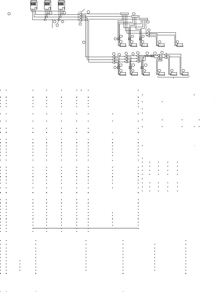
4. Selection of refrigerant piping
Follower Unit Follower Unit Header Unit
Outdoor unit
1Outdoor unit connecting piping
C |
B |
A |
|
|
|
|
|
|
Balance pipe |
1st branching section |
|
|
|
|
|
4 |
Liquid pipe |
|
|
|
|
1 |
1 |
8 |
Y-Shape branching joint |
||
|
|
Discharge gas pipe |
||||
|
|
|
|
|||
|
|
|
|
|
|
|
|
|
|
|
Suction gas pipe |
|
|
|
2 |
3 Main piping |
|
|
|
4 |
9 |
T-shape |
8 |
|
|
|
|
|
|
|
|
|
|
|
|
|
|
|
|
|
|
|
|
|
||
Main connecting piping |
branching joint |
|
|
|
|
|
|
|
8 Y-Shape branching joint |
|
||
between outdoor units |
|
|
|
|
|
|
|
|
|
|
|
|
|
|
|
10 |
|
5 |
5 |
|
5 |
|
|
|
|
|
|
|
FS unit |
|
|
|
|
|
|
|
||
|
|
4 |
|
|
6 |
6 |
|
6 |
|
7 |
7 |
|
|
|
|
|
|
|
|
|
|
< Cooling only > |
< Cooling only > |
||
|
|
Liquid pipe |
8 |
4 |
8 |
4 |
8 |
4 |
4 |
4 |
|
|
|
|
|
|
|
|
|
|
|
|
|
||
|
|
Discharge gas pipe |
|
|
|
|
|
|
|
|
|
|
|
|
Suction gas pipe |
|
|
|
|
|
|
|
|
|
|
|
|
|
10 |
|
5 |
5 |
|
5 |
|
|
|
|
|
|
|
FS unit |
|
|
|
|
|
|
|
||
|
|
|
|
|
6 |
6 |
|
6 |
|
6 |
6 |
6 |
Indoor unit
Group control
* Selection of refrigerant piping
No. |
Item |
Suction |
Discharge |
Liquid side |
|
Outdoor unit model name |
||
|
|
gas side |
gas side |
|
|
|
|
|
|
Pipe size of outdoor |
Ø 22.2 |
Ø 19.1 |
Ø 12.7 |
— |
MMY-MAP0802FT8 |
||
|
Ø 22.2 |
Ø 19.1 |
Ø 12.7 |
MMY-MAP1002FT8 |
||||
|
unit |
|||||||
|
Ø 28.6 |
Ø 19.1 |
Ø 12.7 |
MMY-MAP1202FT8 |
||||
|
|
|
||||||
|
|
|
|
|
|
Total capacity code of indoor units at |
||
No. |
Item |
Suction |
Discharge |
Liquid side |
Balance |
downstream side |
||
gas side |
gas side |
pipe |
Equivalent to |
Equivalent to HP |
||||
|
|
|
||||||
|
|
|
|
|
|
capacity |
||
|
|
|
|
|
|
|
||
|
Connecting pipe size |
Ø 28.6 |
Ø 22.2 |
Ø 15.9 |
Ø 9.5 |
Below 61.5 |
Below 22 |
|
|
between outdoor units |
|||||||
|
|
|
|
|
|
|
||
|
|
Suction |
Discharge |
|
|
Total capacity code of all outdoor units |
||
No. |
Item |
Liquid side |
|
Equivalent to |
|
|||
|
|
gas side |
gas side |
|
|
Equivalent to HP |
||
|
|
|
|
|
|
capacity |
||
|
|
|
|
|
|
|
||
|
|
Ø 22.2 |
Ø 19.1 |
Ø 12.7 |
|
Below 33.5 |
Below 12 |
|
|
Size of main pipe |
Ø 28.6 |
Ø 19.1 |
Ø 12.7 |
— |
33.5 |
12 |
|
|
Ø 28.6 |
Ø 22.2 |
Ø 19.1 |
45.0 to below 61.5 |
16 to below 22 |
|||
|
|
Ø 34.9 |
Ø 28.6 |
Ø 19.1 |
|
61.5 to below 73.0 |
22 to below 26 |
|
|
|
Ø 34.9 |
Ø 28.6 |
Ø 22.2 |
|
73.0 or more |
26 or more |
|
|
|
Suction |
Discharge |
|
|
Total capacity code of all indoor units |
||
No. |
Item |
Liquid side |
|
Equivalent to |
|
|||
|
|
gas side |
gas side |
|
|
Equivalent to HP |
||
|
|
|
|
|
|
capacity |
||
|
|
|
|
|
|
|
||
|
|
Ø 15.9 |
Ø 12.7 |
Ø 9.5 |
|
Below 18.0 |
Below 6.4 |
|
|
Pipe size between |
Ø 22.2 |
Ø 19.1 |
Ø 12.7 |
— |
18.0 to below 34.0 |
6.4 to below 12.2 |
|
|
branching sections |
Ø 28.6 |
Ø 22.2 |
Ø 15.9 |
34.0 to below 56.5 |
12.2 to below 20.2 |
||
|
*1 *2 *3 |
Ø 34.9 |
Ø 28.6 |
Ø 15.9 |
|
56.5 to below 70.5 |
20.2 to below 25.2 |
|
|
|
Ø 34.9 |
Ø 28.6 |
Ø 19.1 |
|
70.5 or more |
25.2 or more |
|
|
Pipe size between the |
Ø 15.9 |
Ø 12.7 |
Ø 9.5 |
— |
Below 18.0 |
Below 6.4 |
|
|
end of branch and FS |
|
|
|
|
|
||
|
Ø 22.2 |
Ø 19.1 |
Ø 12.7 |
18.0 or more |
6.4 or more |
|||
|
unit |
|||||||
|
|
|
|
|
|
|
||
No. |
Item |
Suction |
Discharge |
Liquid side |
|
Capacity rank of indoor unit |
||
|
|
gas side |
gas side |
|
|
|
|
|
|
|
Ø 9.5 |
— |
Ø 6.4 |
|
007 to 012 Type |
||
|
Piping of indoor unit |
Ø 12.7 |
— |
Ø 6.4 |
— |
015 to 018 Type |
||
|
Ø 15.9 |
— |
Ø 9.5 |
024 to 056 Type |
||||
|
|
|||||||
|
|
Ø 22.2 |
— |
Ø 12.7 |
|
072 to 096 Type |
||
|
|
Ø 9.5 |
— |
Ø 6.4 |
|
15m or less |
007 to 012 Type |
|
|
Piping of cooling only |
Ø 12.7 |
|
Ø 9.5 |
— |
15m above |
||
|
|
|
||||||
|
indoor unit (Between |
Ø 12.7 |
— |
Ø 6.4 |
15m or less |
015 to 018 Type |
||
|
branching and indoor |
Ø 15.9 |
|
Ø 9.5 |
15m above |
|||
|
|
|
|
|||||
|
unit) *2 |
Ø 15.9 |
— |
Ø 9.5 |
— |
024 to 056 Type |
||
|
|
Ø 22.2 |
— |
Ø 12.7 |
072 to 096 Type |
|||
* Selection for branching section
Selection of FS unit
|
Total capacity code of |
Max.No. of |
|||
Model Name |
indoor unit |
connected |
|||
|
Equivalent to |
Equivalent |
indoor |
||
|
capacity (kW) |
to HP |
units |
||
RBM-Y1122FE |
Below 11.2 |
Below 4.0 |
5 |
||
RBM-Y1802FE |
11.2 to below |
4.0 to below |
8 |
||
18.0 |
6.4 |
|
|||
|
|
|
|||
RBM-Y2802FE |
18.0 to 28.0 |
6.4 to 10.0 |
8 |
||
or less |
or less |
||||
|
|
||||
|
|
|
|
|
|
* Minimum wall thickness for R410A
application
|
Half |
Outer |
Outer |
Minimum |
|
Soft |
Hard |
Wall |
|||
dia. |
dia. |
||||
|
or |
(Inch) |
(mm) |
Thickness |
|
|
Hard |
(mm) |
|||
OK |
OK |
1/4” |
6.35 |
0.80 |
|
|
|
|
|
|
|
OK |
OK |
3/8” |
9.52 |
0.80 |
|
|
|
|
|
|
|
OK |
OK |
1/2” |
12.70 |
0.80 |
|
|
|
|
|
|
|
OK |
OK |
5/8” |
15.88 |
1.00 |
|
|
|
|
|
|
|
NG |
OK |
3/4” |
19.05 |
1.00 |
|
NG |
OK |
7/8” |
22.20 |
1.00 |
|
NG |
OK |
1.1/8” |
28.58 |
1.00 |
|
|
|
|
|
|
|
NG |
OK |
1.3/8” |
34.92 |
1.10 |
|
|
|
|
|
|
*1 In case the pipe exceeds main pipe size, it should be the same as main pipe size.
*2 2 pipes for cooling only indoor unit shall be used with liquid pipe and suction gas pipe.
*3 2 pipes from FS unit to branching section shall be used with liquid pipe and suction gas pipe.
*4 Branching pipe on the 1st branch should be selected according to the capacity code for outdoor unit.
*5 In case total capacity code for indoor units shall be exceeded to capacity code for outdoor unit, the pipe size should be selected with capacity code for outdoor unit.
*6 For 1 line after header branching, indoor units with a maximum of 6.0 capacity code in total can be connected.
No. |
|
|
Total capacity code of indoor unit |
Model Name |
|||
|
|
||||||
|
|
|
Equivalent to capacity |
|
Equivalent to HP |
For 3 piping |
For 2 piping |
|
Y-Shape branching joint |
Below 18.0 |
|
Below 6.4 |
RBM-BY53FE |
RBM-BY53E |
|
|
18.0 to below 40.0 |
|
6.4 to below 14.2 |
RBM-BY103FE |
RBM-BY103E |
||
|
*4 *5 |
40.0 to below 70.5 |
|
14.2 to below 25.2 |
RBM-BY203FE |
RBM-BY203E |
|
|
|
|
70.5 or more |
|
25.2 or more |
RBM-BY303FE |
RBM-BY303E |
|
Branching |
For |
Below 40.0 |
|
Below 14.2 |
RBM-HY1043FE |
RBM-HY1043E |
|
4 Branching |
40.0 to below 70.5 |
|
14.2 to below 25.2 |
RBM-HY2043FE |
RBM-HY2043E |
|
|
Header |
For |
Below 40.0 |
|
Below 14.2 |
RBM-HY1083FE |
RBM-HY1083E |
|
*4, *5, *6 |
|
|||||
|
|
8 Branching |
40.0 to below 70.5 |
|
14.2 to below 25.2 |
RBM-HY2083FE |
RBM-HY2083E |
|
|
|
1 set of 4 types of T-shape joint pipes as described below : The rewired |
|
|
||
|
T-Shape branching joint |
quantity is arranged and combined at the site. |
|
|
|
||
|
- Balance pipe (Ø 9.52) X 1 |
|
|
|
|||
|
(For connecting outdoor |
- Piping at liquid side (Ø 12.7 to Ø 22.2) X 1 |
|
RBM-BT13FE |
|||
|
unit) |
- Piping at discharge gas side (Ø 19.1 to Ø 28.6) X 1 |
|
|
|||
|
|
|
|
|
|||
|
|
|
- Piping at suction gas side (Ø 22.2 to Ø 38.1) X 1 |
|
|
||
28

5. Charging requirement with additional refrigerant
After the system has been vacuumed, replace the vacuum pump with a refrigerant cylinder and charge the system with additional refrigerant.
Calculating the amount of additional refrigerant required
Refrigerant in the system when shipped from the factory |
R410A |
||||
|
|
||||
|
|
|
|
|
|
|
|
8HP |
10HP |
12HP |
|
|
|
|
|
|
|
Refrigerant amount charged in factory |
Heat recovery model |
11.5kg |
11.5kg |
11.5kg |
|
|
|
|
|
|
|
When the system is charged with refrigerant at the factory, the amount of refrigerant needed for the pipes at the site is not included. Calculate the additional amount needed, and add that amount to the system.
(Calculation)
Additional refrigerant charge amount is calculated from size of liquid pipe at site and its real length.
[Additional refrigerant charge amount at site] = |
|
|
|
|
|
|
||
[Real length of liquid pipe] × |
|
Additional refrigerant charge amount |
|
× 1.3 + |
Compensation by |
|
|
|
|
per liquid pipe 1m (Table 1) |
|
|
system HP (Table 2) |
|
|||
|
|
|
|
|
|
|
|
|
Example : Additional charge amount R (kg) = {(L1 x 0.025kg/m) + (L2 x 0.055kg/m) + (L3 x 0.105kg/m) + (L4 x 0.160kg/m) + (L5 x 0.250kg/m)} x 1.3
|
|
|
|
|
|
|
L1 |
: Real total length of liquid pipe Ø6.4 (m) |
|
||||||
|
|
|
|
|
|
|
L2 |
: Real total length of liquid pipe Ø9.5 (m) |
|
||||||
|
|
|
|
|
|
|
L3 |
: Real total length of liquid pipe Ø12.7 (m) |
|
||||||
|
|
|
|
|
|
|
L4 |
: Real total length of liquid pipe Ø15.9 (m) |
|
||||||
|
|
|
|
|
|
|
L5 |
: Real total length of liquid pipe Ø19.1 (m) |
|
||||||
|
|
|
|
|
|
|
System : 24HP |
|
|
|
|
||||
Table 1 |
|
|
|
|
|
|
|
|
|
|
|
|
|
|
|
|
|
|
|
|
|
|
|
|
|
|
|
|
|
|
|
Pipe dia. at liquid side |
|
|
|
|
Ø6.4 |
|
Ø9.5 |
|
Ø12.7 |
Ø15.9 |
Ø19.1 |
Ø22.2 |
|||
|
|
|
|
|
|
|
|
|
|
|
|
|
|
|
|
Additional refrigerant amount/1m |
|
0.025kg |
|
0.055kg |
|
0.105kg |
0.160kg |
0.250kg |
0.350kg |
||||||
|
|
|
|
|
|
|
|
|
|
|
|
|
|
|
|
Table 2 |
|
|
|
|
|
|
|
|
|
|
|
|
|
|
|
|
|
|
|
|
|
|
|
|
|
|
|
|
|||
Combined |
|
Outdoor |
|
|
|
Compensation |
|
|
|
|
|
|
|||
horse power |
combination (HP) |
|
by system HP |
|
|
|
|
|
|||||||
(HP) |
|
|
|
|
|
|
(kg) |
|
|
|
|
|
|||
|
|
|
|
|
|
|
|
|
|
|
|
|
|
||
8 |
8 |
|
|
|
|
|
2.0 |
|
|
|
|
|
|
||
|
|
|
|
|
|
|
|
|
|
|
|
|
|
||
10 |
10 |
|
|
|
|
|
2.5 |
|
|
|
|
|
|
||
|
|
|
|
|
|
|
|
|
|
|
|
|
|
||
12 |
12 |
|
|
|
|
|
3.0 |
|
|
|
|
|
|
||
|
|
|
|
|
|
|
|
|
|
|
|
|
|
||
16 |
8 |
8 |
|
|
|
|
-1.5 |
|
|
|
|
|
|
||
|
|
|
|
|
|
|
|
|
|
|
|
|
|
||
18 |
10 |
8 |
|
|
|
|
0.0 |
|
|
|
|
|
|
||
|
|
|
|
|
|
|
|
|
|
|
|
|
|
||
20 |
10 |
10 |
|
|
|
|
2.0 |
|
|
|
|
|
|
||
|
|
|
|
|
|
|
|
|
|
|
|
|
|
||
24 |
8 |
8 |
|
8 |
|
|
-4.5 |
|
|
|
|
|
|
||
|
|
|
|
|
|
|
|
|
|
|
|
|
|
||
26 |
10 |
8 |
|
8 |
|
|
-3.0 |
|
|
|
|
|
|
||
|
|
|
|
|
|
|
|
|
|
|
|
|
|
||
28 |
10 |
10 |
|
8 |
|
|
-1.5 |
|
|
|
|
|
|
||
|
|
|
|
|
|
|
|
|
|
|
|
|
|||
30 |
10 |
10 |
|
10 |
|
0.0 |
|
|
|
|
|
|
|||
|
|
|
|
|
|
|
|
|
|
|
|
|
|
|
|
29

6. WIRING DESIGN
1.General
(1)Perform wiring of the power supply in conformance with the regulations of the local electric company.
(2)For the control wires connecting indoor units, and between indoor and outdoor units, use of double-core shield wires is recommended to prevent noise trouble.
(3)Be sure to set the earth leakage breaker and the switches to the power supply section of the indoor unit.
(4)Supply power to each outdoor unit and provide an earth leakage breaker or hand switch for each outdoor unit.
(5)Never connect the 220–240V power to the terminal block (U1, U2, U3, U4, U5, U6) for control cables. (Trouble is caused.)
(6)Store wiring system for control and refrigerant piping system in the same line.
(7)Arrange the cables so that the electric wires do not come to contact with high-temperature part of the pipe ; otherwise coating melts and an accident may be caused.
(8)Do not turn on power of the indoor unit until vacuuming of the refrigerant pipe will finish.
2.For outdoor unit power supply
•Select the power supply cabling and fuse of each outdoor unit from the following specifications: Cable 5-core, in conformance with Design 60245 IEC 66
•Do not connect them via the incorporated terminal block (L1, L2, L3, N).
L1 |
L2 L3 |
N |
Outdoor power supply 3-phase 380-415V, 50Hz
3. Electrical wiring design
L1 L2 L3
N
L1 L2 L3
N
3-phase
50Hz 380-415V
Earth leakage breaker hand switch
Outdoor power source
Earth |
|
|
|
Pull box |
|
|
Indoor |
|
FS unit |
FS unit |
FS unit |
FS unit |
|
|
|
|
|
|
power source |
|
|
|
|
|
|
Single phase |
|
|
|
|
|
50Hz 220-240V |
Indoor unit |
Indoor unit |
Indoor unit |
Indoor unit |
|
Earth leakage breaker |
||||
|
|
|
|
|
|
|
power switch |
|
|
|
|
|
|
FS unit |
FS unit |
FS unit |
FS unit |
Indoor unit |
Indoor unit |
Indoor unit |
Indoor unit |
• Unit capacities and power supply wire sizes (Reference)
Model |
Power supply wiring |
|
|
MMY- |
Wire size |
|
Field fuse |
MAP0802FT8 |
3.5 mm² (AWG #10) Max. 20 m |
|
30 A |
|
|
|
|
MAP1002FT8 |
5.5 mm² (AWG #10) Max. 28 m |
|
30 A |
MAP1202FT8 |
5.5 mm² (AWG #10) Max. 27 m |
|
30 A |
|
|
|
|
•Determine the wire size for indoor unit according to the number of connected indoor units downstream.
•Observe local regulation regarding wire size selection and installation.
30
Loading...