


Toshiba MMY-MAP0601HT8, TCB-PCNT30TLE, RBC-AS21E2, RBC-EXW21E2, RBC-AMT21E INSTALLATION MANUAL
...FILE NO. A04-007
APPLICATION CONTROL MANUAL
Super Modular Multi System
Heat Pump Type |
R410A |
Cooling Only Type |
Super Heat Recovery Multi System
Heat Recovery Type

CONTENTS
1 Outline of system and application control
1-1 Outline of application control ................................................................................................... |
5 |
|
1-2 List of application control models and setting .......................................................................... |
6 |
|
1-3 |
Remote controller .................................................................................................................... |
7 |
1-4 Application controls for remote controller .............................................................................. |
10 |
|
|
1-4-1 Application for indoor remote controller ....................................................................... |
10 |
|
1-4-2 Two remote control ....................................................................................................... |
11 |
|
1-4-3 Group control ............................................................................................................... |
12 |
|
1-4-4 Application controls for central remote controller ......................................................... |
13 |
1-5 Application controls of indoor unit ......................................................................................... |
15 |
|
1-6 Application controls of outdoor unit ....................................................................................... |
15 |
|
1-7 |
Application controls by optional P.C. board of outdoor unit .................................................... |
16 |
1-8 |
Application controls by optional devices connected to indoor unit ........................................ |
19 |
1-9 |
Application control for network (Tentative) ............................................................................ |
21 |
|
1-9-1 Touch screen controller system ................................................................................... |
21 |
|
1-9-2 LONWORKS ............................................................................................................... |
22 |
|
1-9-3 Windows based central controller ................................................................................ |
23 |
|
1-9-4 BACnet ........................................................................................................................ |
23 |
2 System wiring diagram and control wiring method
2-1 Applicable model and connectable units ............................................................................... |
25 |
|
2-2 |
System wiring diagram .......................................................................................................... |
26 |
|
2-2-1 For VRF system only ................................................................................................... |
26 |
|
2-2-2 For combined system with “1:1 model” ........................................................................ |
27 |
2-3 |
Design of control wiring ......................................................................................................... |
28 |
2-4 |
Earth method of shield wiring ................................................................................................ |
29 |
|
2-4-1 For VRF system only ................................................................................................... |
29 |
|
2-4-2 For combined system with “1:1 model” ........................................................................ |
30 |
2-5 |
General requirement for control wiring .................................................................................. |
31 |
3 Address setup
3-1 |
Definition of address ............................................................................................................. |
34 |
3-2 |
Address setup procedure ..................................................................................................... |
38 |
|
3-2-1 Check at main power-ON ............................................................................................ |
39 |
|
3-2-2 Automatic address setup ............................................................................................. |
40 |
|
3-2-3 Manual address setup from remote controller ............................................................. |
43 |
|
3-2-4 Confirmation of indoor unit address and position by using the remote controller ......... |
44 |
|
3-2-5 Change of indoor address from remote controller ....................................................... |
45 |
|
3-2-6 Address setup example (VRF system) ....................................................................... |
47 |
|
3-2-7 Clearance of address (Return to status (Address undecided) |
|
|
at shipment from factory) ............................................................................................ |
50 |
|
3-2-8 In case of increase the address-undefined indoor units (Extension, etc.) ................... |
51 |
|
3-2-9 How to set central control address .............................................................................. |
52 |
|
3-2-10 Address re-setup for central control of the super-digital inverter |
|
|
and the digital inverter ............................................................................................... |
54 |
|
3-2-11 Indoor address change example (Super-digital inverter and digital inverter) ............ |
58 |
2
4 Details of application control and devices |
|
4-1 Remote controller ................................................................................................................. |
61 |
4-1-1 Wired remote controller (RBC-AMT21E) .................................................................... |
61 |
4-1-2 Simple remote controller (RBC-AS21E) ..................................................................... |
67 |
4-1-3 Wireless remote controller kit ..................................................................................... |
71 |
4-1-4 Weekly timer (RBC-EXW21E) .................................................................................... |
97 |
4-2 Central remote controller (TCB-SC642TLE) ...................................................................... |
107 |
4-2-1 Outline ...................................................................................................................... |
107 |
4-2-2 Installation procedure ............................................................................................... |
112 |
4-2-3 Operation procedure ................................................................................................. |
130 |
4-3 Application controls of indoor unit ...................................................................................... |
136 |
4-3-1 Setup of selecting function in indoor unit .................................................................. |
136 |
4-3-2 Ventilation fan control from remote controller ............................................................ |
139 |
4-3-3 Leaving-ON prevention control ................................................................................. |
140 |
4-3-4 Power peak-cut from indoor unit ............................................................................... |
140 |
4-3-5 Remote sensor (TCB-TC21LE) ................................................................................ |
141 |
4-4 Application controls of outdoor unit .................................................................................... |
142 |
4-4-1 Outdoor fan high static pressure shift ....................................................................... |
143 |
4-4-2 Cooling priority, heating priority control ..................................................................... |
143 |
4-4-3 Indoor unit setup in “Specific indoor unit priority control” mode ................................. |
144 |
4-5 Application controls by optional P.C. board of outdoor unit ................................................. |
145 |
4-5-1 Power peak-cut control ............................................................................................. |
150 |
4-5-2 Snowfall fan control .................................................................................................. |
152 |
4-5-3 External master ON/OFF control .............................................................................. |
152 |
4-5-4 Night operation control .............................................................................................. |
153 |
4-5-5 Operation mode selection control ............................................................................. |
153 |
4-6 Application controls by optional devices connected to indoor unit ..................................... |
154 |
4-6-1 Remote control by “remote location ON/OFF control box” ....................................... |
154 |
4-6-2 Central control by AI-NETWORK central controller (Network adapter) ................... |
157 |
4-6-3 Central control with “1:1 model” (“1:1 model” connection interface) .......................... |
163 |
5 Dimensional drawing |
|
3

1
OUTLINE OF SYSTEM
AND
APPLICATION CONTROL
1-1 Outline of application control
1-2 List of application control models and setting 1-3 Remote controller
1-4 Application controls for remote controller 1-4-1 Applications for indoor remote controller 1-4-2 Two remote control
1-4-3 Group control
1-4-4 Application controls for central remote controller 1-5 Application controls of indoor unit
1-6 Application controls of outdoor unit
1-7 Application controls by optional P.C.board of outdoor unit
1-8 Application controls by optional devices connected to indoor unit 1-9 Application control for network (Tentative)
1-9-1 Touch screen controller system
1-9-2 LONWORKS
1-9-3 Windows based central controller
1-9-4 BACnet
4

1-1 Outline of application control
LON Gateway
LONWORKS
BMS-LSV2E
|
Intelligent |
TCS-Net Interface |
|
|
|
|
|
|||||||
|
server |
|
|
|
|
|
||||||||
|
|
|
|
|
|
|
|
|
|
|
|
|
|
|
|
|
|
BMS-IFLSV1E |
|
|
|
|
|
||||||
Touch screen |
|
|
|
|
|
|
|
Power peak-cut |
|
|
|
|
|
|
|
|
|
|
|
|
|
|
|
|
|
|
|||
controller |
|
|
|
|
|
|
|
control board |
|
|
|
|
|
|
|
|
|
|
|
|
|
TCB-PCDM2E |
|
|
|
|
|
||
|
|
|
|
|
|
|
|
|
|
|
|
|||
|
|
|
|
|
|
|
|
|
|
|
|
|
||
• Monitoring |
|
|
|
|
|
|
|
External master |
|
|
|
|
|
|
|
|
|
|
|
|
|
|
|
|
|
|
|
||
• Remote control |
|
|
|
|
|
|
|
ON/OFF board |
|
|
|
|
|
|
• Schedule operation |
|
|
|
|
|
|
|
TCB-PCMO2E |
|
|
|
|
|
|
|
|
|
|
|
|
|
|
|
|
|
|
|
||
•Error code indication
•Alarm list indication
•Monthly report
•Energy monitoring data
etc. |
|
|
|
Energy meter |
I/F |
|
|
|
|
|
relay interface |
|
|
|
|
|
|
|
Energy |
|
|
|
|
|
|
monitoring |
|
Operationstatus output |
Operationcontrol command |
Powerpeak-cut control signal |
MasterON/OFF signal |
|
Alarm status output |
ON/OFF command |
|
|
|
|
|
Batch drive, error output |
|
|
|
|
|
|
Master ON/OFF signal |
|
|
|
|
|
|
|
Central remote |
|
|
|
|
|
|
controller |
|
|
|
|
|
|
TCB-SC642TLE |
Air-conditioning
Management on site
Weekly timer
RBC-EXW21E
*1 BACnetTM : ANSl/ASHRAE135-1995, A Data CommuniCation Protocol for Bulding Automation and ControI Networks. *2 LoNWoRKS R : Resistered trademark Echelon Corporation.
Outdoor Units (VRF system)
Super Digital Inverter
Digital Inverter
"1:1 model" connection interface TCB-PCNT30TLE
Remote location
ON/OFF control box
TCB-IFCB-4E
Network adapter
TCB-PCNT20E
Master remote controller
Side remote controller
AI-NETWORK
|
Wired remote controller |
|
|
|
RBC-AMT21E |
Wireless remote |
|
|
Sub-remote |
|
|
Weekly timer |
controller |
controller |
|
|
|||
RBC-EXW21E |
RBC-AS21E |
|
AI-NET central |
|
|
|
control devices |
5
1-2 List of application control models and setting
Appliance name |
Model name |
Contents of application control |
Connecting device or setting method |
Reference |
|
|
|
|
No. |
Remote Controller |
|
|
|
|
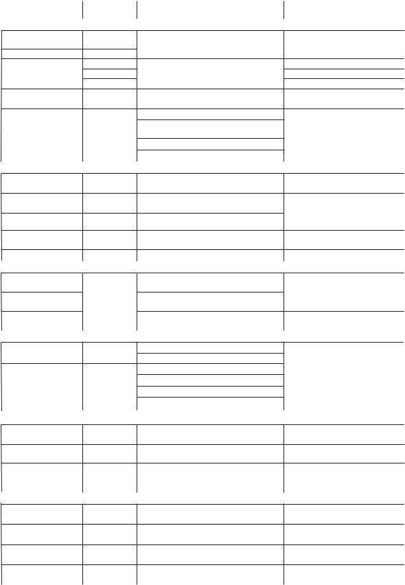
Wired remote controller |
RBC-AMT21E |
•Individual control |
Indoor unit |
|
|
|
•Group control |
|
|
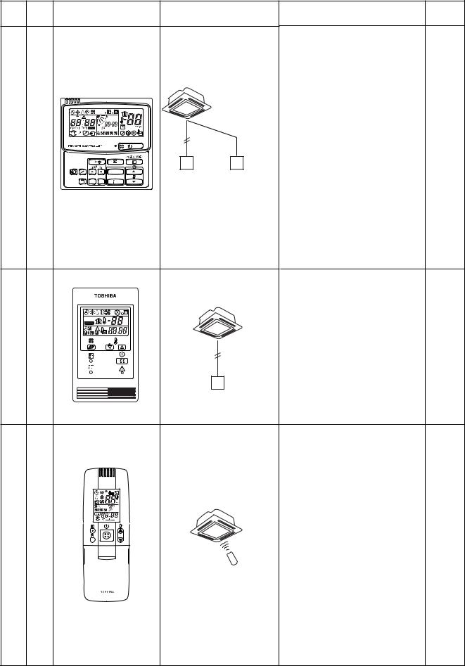
Simple remote controller |
RBC-AS21E |
•Two remote control |
|
|
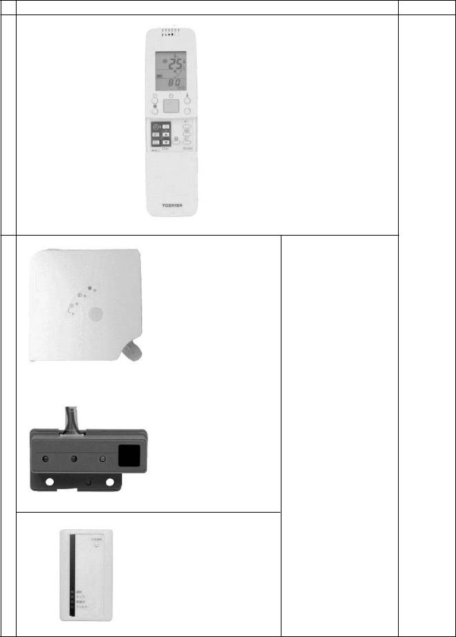
Wireless remote |
TCB-AX21U(W)-E |
•Individual control |
For 4-way sir discharge cassette type |
1-3 |
controller |
RBC-AX22CE |
•Two wireless control |
For under ceiling type |
|
|
TCB-AX21E |
•Two remote control (wired & wireless) |
For other type |
1-4 |
Weekly timer |
RBC-EXW21E |
•Weekly schedule operation |
Wired remote controller |
|
|
|
(main remote controller + weekly timer) |
|
|
Central remote |
TCB-SC642TLE |
•Central control of Max.64 or units |
Outdoor unit |
|
controller |
|
•Weekly schedule operation |
(Indoor unit) |
|
|
|
(central remote controller + weekly timer) |
|
|
|
|
•Central control without indoor remote controller |
|
|
|
|
•Central control with "1:1 model" |
|
|
|
|
|
|
|
Application controls of indoor unit |
|
|
|
|
Function change of |
|
Setting functions necessary to perform |
Item code (DN) setting from |
|
indoor unit |
|
applied control at the local site. |
wired remote controller |
|
Ventilation fan control |
|
Ventilation fan start/stop operation from |
Setting from wired remote |
|
from remote controller |
|
wired remote controller. |
controller and relay wiring |
1-5 |
Leaving-ON |
|
Control to prevent Leaving-ON of indoor |
(local supply) |
|
|
|
|||
prevention control |
|
unit. |
|
|
Demand control from |
|
Thermo-OFF operation by relay signal |
Relay wiring (local supply) |
|
indoor unit |
|
|
||
|
|
|
|
|
Remote sensor |
TCB-TC21LE |
Remote sensing of indoor air temperature |
Indoor unit |
|
|
|
|
|
|
Application controls of outdoor unit |
|
|
|
|
Outdoor fan high static |
|
Change of outdoor fan control when connecting |
Switch setting on outdoor |
|
pressure shift |
|
a duct to discharge port of outdoor unit. |
interface P.C. board |
1-6 |
Control for cooling/ |
|
Change operation mode priority |
||
|
|
|||
heating priority |
|
|
|
|
|
|
|
|
|
Specific indoor unit |
|
Specific indoor unit has the priority for |
Item code (DN) setting from wired |
|
priority control |
|
operation mode. |
remote controller |
|
Optional P.C. board of outdoor unit |
|
|
|
|
Power peak-cut |
TCB-PCDM2E Power peak-cut (Standard function) |
Inverter assembly of the header |
|
|
control board |
|
Power peak-cut (Expansion function) |
outdoor unit |
|
External master |
TCB-PCMO2E |
Snowfall fan control |
|
1-7 |
ON/OFF control board |
|
External master ON/OFF control |
|
|
|
|
Night operation (sound reduction) control |
|
|
|
|
Operation mode selection control |
|
|
|
|
|
||
Optional devices connected to indoor unit |
|
|
||
Remote location |
TCB-IFCB-4E |
•Monitoring from outside |
Indoor unit |
|
ON/OFF control box |
|
•ON/OFF command from external signals |
|
|
Network adapter |
TCB-PCNT20E |
Central control with AI-Network system |
Indoor unit |
1-8 |
"1:1 model" connection TCB-PCNT30TLE |
Central control with "1:1 model" |
Indoor unit |
|
|
interface |
|
(link Toshiba Digital Inverter system |
|
|
|
|
and Super Digital Inverter system) |
|
|
|
|
|
|
|
Application control for network |
|
|
|
|
Touch screen controller |
BMS-TP5120ACE Combination of touch screen and local |
Central control wiring |
|
|
system |
etc. |
server (monitoring, remote operation, etc) |
|
|
LONWORKS |
TCB-IFLN*** |
LONWORKS interface connected to |
Central control wiring |
1-9 |
|
etc. |
building management computer |
|
|
Windows based |
BMS-LSV*** |
Local server is "Plug-in" into customer's |
Central control wiring |
|
central controller |
etc. |
personal computer |
|
|
BACnet |
BMS-LSV*** |
Local server is connected under the |
Central control wiring |
|
|
etc. |
BACnet network. |
|
|
|
|
|
|
|
6
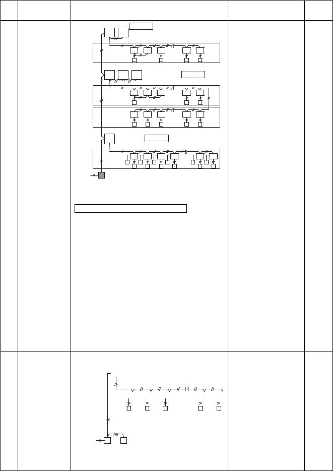
1-3 Remote controller
Model Name name
Wired remote controller |
RBC-AMT21E |
Simple remote controller |
RBC-AS21E |
|
|
|
(W)-E |
Wireless remote controller kit |
|
TCB-AX21U |
RBC-AX22CE |
||
|
AX21E |
|
|
|
TCB- |
Appearance |
Application |
|
Function |
Reference |
|
|
N o . |
||||
|
|
|
|
|
|
|
|
Connected to indoor unit |
• |
Start / Stop |
|
|
|
• |
Changing mode |
|
|
|
|
|
• |
Temperature setting |
|
|
|
|
• |
Air flow changing |
|
|
|
|
• |
Timer function |
|
|
|
|
|
Either “ON” time or “OFF” time |
|
|
|
|
|
or “CYCLIC” can be set how |
|
|
|
|
|
many 30 min. later ON or OFF is |
|
|
|
CODE No. |
|
operated. |
|
SET DATA |
|
|
|
Combined with the weekly timer, |
|
|
UNIT No. |
|
|
|
|
SETTINGTEST |
R.C. No. |
|
|
weekly schedule operation can |
|
|
|
|
• |
be operated. |
1-4 |
|
|
|
Filter sign |
4-1-1 |
|
|
|
|
|
Displays automatically maintenance |
|
|
|
|
|
|
|
|
UNIT |
|
|
time of indoor filter. |
|
|
Wired remote Wired remote controller |
|
Filter sign flashes. |
|
|
|
|
|
|
||
SET CL |
|
controller (In case of control by |
• |
Self-diagnosis function |
|
|
|
2 remote controllers) |
|
||
|
|
|
|
Pressing “CHECK” button displays |
|
|
|
|
|
cause of trouble on the check code. |
|
|
|
|
• Control by 2 remote controllers is |
|
|
|
|
|
|
available. |
|
|
|
|
|
Two remote controllers can be |
|
|
|
|
|
connected to one indoor unit. The |
|
|
|
|
|
indoor unit can be separately |
|
|
|
|
|
operated from the isolated places. |
|
|
|
Connected to indoor unit |
• |
Start / Stop |
|
|
|
• |
Temperature setting |
|
|
|
|
|
• |
Air flow changing |
|
|
|
|
• |
Check code display |
|
TEST |
˚C |
|
|
|
|
SETTING |
˚F |
|
|
|
|
1-4
4-1-2
Simple remote controller
• |
Start / Stop |
|
• |
Changing mode |
|
• |
Temperature setting |
|
• |
Air flow changing |
|
• |
Timer function |
|
Connected to indoor unit |
Either “ON” time or “OFF” time or |
|
“CYCLIC” can be set how many 30 |
|
|
|
min. later ON or OFF is operated. |
|
• Control by 2 remote controllers is |
|
|
|
available. |
|
|
Two wireless remote controllers can |
1-4 |
|
operate one indoor unit. The indoor |
4-1-3 |
|
unit can be separately operated |
|
|
|
|
|
from the isolated places. |
|
• |
Check code display |
|
TCB-AX21U (W)-E |
|
|
(For 4-way Air Discharge Cassette) |
|
|
RBC-AX22CE |
|
|
(For Under Ceiling) |
|
|
TCB-AX21E |
|
|
(For others except concealed duct |
|
|
high static pressure type) |
|
|
7
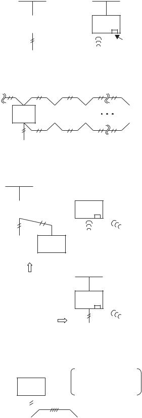
Wireless remote controller kit (Kit of Hand set and receiver unit)
Wireless remote controller
Sensor unit (receiver unit)
Outlook and function |
Reference No. |
Wireless remote controller
(Common for all indoor unit type)
TCB-AX21U(W)-E
(for 4-way Air Discharge
Cassette type)
186W x 186D
(Mounted to the corner of 4-1-3 ceiling panel)
|
• Check code display |
|
|
|
(sensor block display on |
|
the receiving unit) |
TCB-AX22CE |
• Test operation |
(For under Ceiling type) |
(Switch setting on the |
|
receiver unit) |
130W x 65H |
• Emergency operation |
(Mounted to the display |
|
position of front cover) |
(Push “emergency |
|
operation” button on the |
|
receiver unit) |
TCB-AX21E
(Universal type for other indoor unit except high static pressure duct type. )
70W x 120H
(Placed on the wall,etc)
8

Model Name name
Weekly timer |
RBC-EXW21E |
Central remote controller |
TCB-SC642TLE |
Appearance |
Application |
|
|
|
Performance |
|
Reference |
||||||
|
|
|
|
N o . |
|||||||||
|
|
|
|
|
|
|
|
|
|
|
|
|
|
|
|
|
|
|
|
• |
Weekly schedule operation |
|
|
||||
|
|
|
Connected to central |
|
Setting different start / stop time |
|
|||||||
|
|
|
remote controller, |
|
|
||||||||
|
|
|
|
for each day of the week |
|
|
|||||||
|
|
|
wired remote controller |
|
|
|
|||||||
|
|
|
|
|
|
|
|
|
|
||||
|
|
|
|
|
|
|
|
ON / OFF can be easily set 3 |
|
||||
|
|
|
|
|
|
|
|
times a day. |
|
|
|
|
|
|
|
|
|
|
|
|
ON |
OFF ON |
OFF ON |
OFF |
|
||
|
|
|
|
|
|
|
8:00 |
12:00 |
13:00 |
18:00 |
19:00 |
21:00 |
|
|
|
|
Wired |
|
|
Weekly |
|
“CHECK” “PROGRAM” “DAY” |
|
||||
|
|
|
|
|
|
button make setting copy easy. |
|
||||||
|
|
SuMoTuWeTh Fr Sa |
remote controller |
|
|
timer |
|
|
|||||
PROGRAM1 |
|
|
|
|
|
|
|
|
|
|
|||
|
|
|
|
|
|
|
Two patterns of schedule for a |
1-4 |
|||||
PROGRAM3 |
|
ERROR |
|
|
|
|
|
||||||
PROGRAM2 |
|
|
|
|
|
|
|
|
|
|
|
|
|
|
|
|
|
|
|
|
|
week can be specified. |
|
4-1-4 |
|||
WEEKLY TIMER |
|
|
|
|
|
|
(Summer schedule and winter |
||||||
|
|
|
|
|
|
|
|
schedule, etc.) |
|
|
|
|
|
|
|
|
|
Outdoor unit |
|
“CANCEL” “DAY” button make |
|
||||||
|
|
|
|
|
|
|
|
|
|||||
|
|
|
|
|
|
|
|
holiday setting easy. |
|
|
|
||
|
|
|
|
|
|
|
|
If power supply fails, the setting |
|
||||
|
|
|
|
|
|
|
|
contents are stored in memory, |
|
||||
|
|
|
|
|
|
|
|
for 100 hours. |
|
|
|
|
|
|
|
|
Central |
|
|
Weekly |
|
|
|
|
|
|
|
|
|
|
remote controller |
|
|
timer |
|
|
|
|
|
|
|
|
|
|
|
|
|
• Individual control up to 64 indoor |
|
||||||
|
|
|
Connected to outdoor unit, |
units. |
|
|
|
|
|
||||
|
|
|
indoor unit |
|
• Individual control for max. 64 indoor |
|
|||||||
|
|
|
|
|
|
|
|||||||
|
|
|
Header |
|
Follower |
units divided 1 to 4 zone. |
|
|
|
||||
|
|
|
|
|
Up to 16 indoor units for each |
|
|||||||
|
|
|
|
|
|
|
|
||||||
|
|
|
|
|
|
|
|
zone |
|
|
|
|
|
|
|
|
|
|
|
• Up to 16 outdoor header units are |
|
||||||
|
|
|
|
|
|
|
connectable. |
|
|
|
|
|
|
|
|
|
|
|
|
• 4 type central control setting to |
|
||||||
ZONE |
|
|
|
|
|
|
inhibit individual operation by remote |
|
|||||
ALL ZONE |
|
|
|
|
|
|
|
|
|
|
|
|
|
GROUP |
|
No. |
|
|
|
|
controller can be selected. |
|
|
||||
|
|
|
|
|
|
|
|
||||||
|
|
CODE |
Outdoor unit |
|
|
|
|
|
|
|
|
|
|
1234 |
UNIT No. |
TEST |
|
|
|
|
|
|
|
|
|
||
SET DATA |
|
|
|
|
|
• Setting for one of 1 to 4 zone is |
|
||||||
SETTING R.C. |
No. |
|
|
|
|
|
|||||||
|
|
|
|
|
|
|
|||||||
|
|
|
|
|
|
|
available. |
|
|
|
|
1-4-4 |
|
|
|
GROUP |
|
|
|
• Usable with other central control |
|||||||
SELECT |
ZONE |
|
|
|
4-2 |
||||||||
|
|
|
|
|
|
|
devices (Up to 10 central control |
||||||
|
|
|
Central |
|
|
|
|
||||||
|
CL |
SET |
|
|
|
devices in one control circuit) |
|
|
|||||
|
|
|
remote controller |
|
|
|
|
||||||
|
|
|
|
|
|
|
|
|
|
|
|
||
|
|
|
|
|
|
• Two control mode selectivity |
|
|
|||||
|
|
|
|
|
|
|
|
Central controller mode |
|
|
|||
|
|
|
|
|
|
|
|
Remote controller mode |
|
|
|||
|
|
|
|
|
|
• Setting of simultaneous ON/OFF 3 |
|
||||||
|
|
|
|
|
|
|
times for each day of the week |
|
|||||
|
|
|
|
|
|
|
combined with weekly timer. |
|
|
||||
|
|
|
Central |
|
|
|
|
|
|
|
|
|
|
|
|
|
remote |
|
|
|
|
|
|
|
|
|
|
|
|
|
controller |
Indoor |
|
|
|
|
|
|
|
|
|
|
|
|
|
|
|
|
|
|
|
|
|
|
|
|
|
|
remote controller |
|
|
|
|
|
|
|
|||
9
1-4 Application controls for remote controller
1-4-1 Applications for indoor remote controller
|
|
Basic function |
|
|
|
|
|
|
|
|
|
|
|
System diagram |
|
|
|
|
|
Model |
|||||||||
|
|
|
|
|
|
|
|
|
|
|
|
|
|
|
|
|
|
|
|
|
|
|
|
|
|
|
|
|
|
|
|
|
|
Main remote controller |
Wireless remote controller |
|
|||||||||||||||||||||||
|
|
|
|
|
|
|
|
|
|
|
|
|
|
|
|
|
|
|
|
|
|
|
|
|
|
|
|
|
• Wired remote controller |
|
|
|
|
|
|
|
|
|
|
|
|
|
|
|
|
|
|
|
|
|
|
|
|
|
|
|
|
|
RBC-AMT21E |
|
|
Individual control |
|
|
|
|
|
|
|
|
|
|
|
|
|
|
|
|
|
|
|
|
|
|
|
|
|
|
• Simple remote controller |
|
|
|
|
|
|
Indoor |
|
|
|
|
|
|
Indoor |
||||||||||||||||
|
Air conditioner is |
|
|
|
|
|
|
|
|
|
|
RBC-AS21E |
|||||||||||||||||
1 |
|
|
|
unit |
|
|
|
|
|
|
|
|
|
|
unit |
|
|
|
|
|
|||||||||
|
|
|
|
|
|
|
|
|
|
|
|
|
|
|
|
|
|
|
|||||||||||
|
|
individually oper- |
|
|
|
|
|
|
|
|
|
|
|
|
|
|
|
|
|
|
|
|
|
|
|
|
|
|
• Wireless remote controller |
|
|
|
|
|
|
|
|
|
|
|
|
|
|
|
|
|
|
|
|
|
|
|
|
|
|
||||
|
|
|
|
|
|
|
|
|
|
Possible up to Max. |
|
|
|
|
|
kit |
|||||||||||||
|
|
ated at a distance. |
|
|
|
|
|
|
|
|
Receiver unit |
||||||||||||||||||
|
|
|
|
|
|
|
|
|
|
|
total length 500m |
|
|
|
|
|
TCB-AX21U(W)-E |
||||||||||||
|
|
|
|
|
|
|
|
|
|
|
|
|
|
|
|
|
|
|
|
|
|
|
|
|
|
|
|
|
RBC-AX22CE |
|
|
|
|
|
|
|
Remote |
|
|
|
|
|
Wireless |
|
|
|
|||||||||||||
|
|
|
|
|
|
|
|
|
|
|
|
|
TCB-AX21E |
||||||||||||||||
|
|
|
|
|
|
|
controller |
|
|
|
|
|
|
remote |
|
||||||||||||||
|
|
|
|
|
|
|
|
|
|
|
|
|
|
|
|
|
|
|
controller |
|
|
||||||||
|
|
|
|
|
|
|
|
|
|
|
|
|
|
|
|
||||||||||||||
|
|
|
|
|
|
|
|
|
|
|
|
|
|
|
|
|
|
|
|
|
|
|
|
|
|
|
|
|
|
|
|
|
|
|
|
|
|
|
|
|
|
|
|
|
|
|
|
|
|
|
|
|
|
|
|
|
|
|
|
|
|
|
|
|
|
|
|
|
|
|
|
|
|
Max.8 indoor units |
|
|
|
|
|
|
|||||||||
|
|
GROUP control |
|
|
|
|
|
|
|
|
|
|
|
|
|
|
|
|
|
|
|
|
|
|
|
|
|
|
• Wired remote controller |
|
|
|
|
Indoor |
|
|
|
Indoor |
|
|
Indoor |
|
|
|
|
|
Indoor |
|
|
||||||||||
|
|
One remote controller |
|
|
|
unit |
|
|
|
unit |
|
|
unit |
|
|
|
|
|
|
unit |
|
|
RBC-AMT21E |
||||||
|
can control group of |
|
|
|
|
|
|
|
|
|
|
|
|
|
|
|
|
|
|||||||||||
2 |
|
|
|
|
|
|
|
|
|
|
|
|
|
|
|
|
|
|
|
|
|
|
|
|
|
|
|
• Simple remote controller |
|
Max. 8 indoor units. |
|
|
|
|
|
|
|
|
|
|
|
|
|
|
|
|
|
|
|
|
|
|
|
|
|
||||
|
|
|
|
|
|
|
|
|
|
|
|
|
|
|
|
|
|
|
|
|
|
|
|
|
|
|
|
RBC-AS21E |
|
|
|
Operating on the |
|
|
|
|
|
|
|
|
|
|
|
|
|
|
|
|
|
|
|
|
|
|
|
|
|
|
|
|
|
|
|
|
|
|
|
|
|
|
|
|
|
|
|
|
|
|
|
|
|
|
|
|
|
|
|||
|
|
same setting |
|
|
|
|
|
|
|
|
|
|
|
|
|
|
|
|
|
|
|
|
|
|
|
|
|
|
|
|
|
|
|
|
Remote |
|
|
|
|
Possible up to Max.total length 500m |
|
||||||||||||||||||
|
|
|
|
|
|
|
|
|
|
|
|||||||||||||||||||
|
|
|
|
|
|
controller |
|
|
|
|
|
|
|
|
|
|
|
|
|
|
|
|
|
|
|
|
|||
|
|
|
|
|
|
|
|
|
|
|
|
|
|
|
|
|
|
|
|
|
|
|
|
|
|
|
|
|
|
|
|
|
|
|
|
|
|
|
|
|
|
|
|
|
|
|
|
|
|
|
|
|
|
|
|
|
|
|
|
|
|
|
|
Wired system |
|
|
|
|
Wireless system |
|
|
|
|
|
|
||||||||||||||
|
|
|
|
|
|
|
|
|
|
|
|
|
|
|
|
|
|
|
|
|
|
|
|
|
|
|
|||
|
|
|
|
|
|
|
|
|
|
|
|
|
|
|
|
|
|
|
|
|
|
|
|
|
|
|
|
|
|
|
|
|
|
|
Indoor |
|
|
|
|
|
|
|
|
Indoor |
|
|
|
|
|
|
|||||||||
|
|
|
|
|
|
unit |
|
|
|
|
|
|
|
unit |
|
|
|
|
|
|
|||||||||
|
|
|
|
|
|
|
|
|
|
|
|
|
|
|
|
|
|
|
|
|
|
|
|
|
|
|
|
|
• Wired remote controller |
|
|
|
|
|
|
|
|
|
|
|
|
|
|
|
|
|
|
|
|
|
|
|
|
|
|
|
|
|
|
|
|
|
|
|
|
|
|
|
|
|
|
|
|
|
|
|
|
|
|
|
|
|
|
|
|
|
|
|
RBC-AMT21E |
|
|
Two remote control |
|
Remote |
|
|
Remote |
|
|
Wireless |
|
Wireless |
|
• Simple remote controller |
|||||||||||||||
|
|
|
|
|
|
remote |
|
|
remote |
|
|||||||||||||||||||
|
Air conditioner is |
|
|
controller |
|
|
controller |
|
|
|
|
|
RBC-AS21E |
||||||||||||||||
3 |
|
|
|
|
controller 1 |
|
controller 2 |
|
|||||||||||||||||||||
|
controlled by two |
|
|
|
|
|
|
|
|
|
|
|
|
|
|
|
|
|
|
|
|
|
|
|
|
|
|
• Wireless remote control- |
|
|
Master |
|
|
Side |
|
|
|
|
|
|
|
|
|
|
|
|
|
|
|||||||||||
|
|
|
|
|
|
Master |
|
Side |
|||||||||||||||||||||
|
|
remote controllers |
|
|
|
|
|
|
|
|
|
|
|
|
|
|
|
ler kit |
|||||||||||
|
|
|
|
|
|
|
|
|
|
|
|
|
|
|
|
|
|
|
|
|
|
|
|
|
|
|
|
||
|
|
at two places. |
|
Possible up to Max. |
|
|
|
|
|
|
|
|
|
|
|
|
|
|
TCB-AX21U(W)-E |
||||||||||
|
|
|
|
|
|
|
|
|
|
|
|
|
|
|
|
|
|
RBC-AX22CE |
|||||||||||
|
|
|
|
total length 500m |
|
|
|
|
|
|
|
|
|
|
|
|
|
|
TCB-AX21E |
||||||||||
|
|
|
|
|
|
|
|
|
|
|
|
|
|
|
|
|
Indoor |
|
|
|
|
|
|
||||||
|
|
|
|
|
|
|
|
|
|
|
|
|
|
|
|
|
unit |
|
|
|
|
|
|
||||||
|
|
|
|
Wired & Wireless |
|
|
|
|
|
|
|
|
|
|
|
|
|
|
|
||||||||||
|
|
|
|
|
|
|
|
|
|
|
|
|
|
|
|
|
|
|
|||||||||||
|
|
|
|
combination control |
|
|
|
|
|
|
|
|
|
|
|
|
|
|
|
||||||||||
|
|
|
|
(Either controller |
|
|
Remote |
|
|
Wireless |
|
|
|||||||||||||||||
|
|
|
|
should be set as |
|
|
controller |
|
|
|
remote |
|
|
||||||||||||||||
|
|
|
|
side controller) |
|
|
|
|
|
|
|
|
|
controller |
|
|
|||||||||||||
|
|
|
|
|
|
|
|
|
|
|
|
|
|
||||||||||||||||
|
|
|
|
|
|
|
|
|
|
|
|
|
|
|
|
|
|
|
|
|
|
|
|
|
|
|
|
|
|
|
|
|
|
|
|
|
|
|
|
|
|
|
|
|
|
|
|
|
|
|
|
|
|
|
|
|
|
|
|
|
|
|
|
|
|
|
|
|
|
|
|
|
|
|
|
Weekly timer function |
|
||||||||||||
|
|
|
|
|
|
|
|
|
|
|
|
|
|
|
|
||||||||||||||
|
|
|
|
|
|
|
|
|
|
|
|
|
|
|
|
|
• Setting of ON-OFF |
|
|||||||||||
|
|
Control by |
|
|
|
|
|
|
|
|
|
|
|
|
|
|
3 times par day |
• Wired remote controller |
|||||||||||
|
|
|
|
|
|
Indoor |
|
|
|||||||||||||||||||||
|
|
|
|
|
|
|
|
• Timer time is displayed. |
|||||||||||||||||||||
|
|
weekly timer |
|
|
|
|
|
|
RBC-AMT21E |
||||||||||||||||||||
4 |
|
|
|
|
|
unit |
|
|
|
|
|
|
• Designation of holiday |
+ |
|||||||||||||||
Weekly schedule |
|
|
|
|
|
|
|
|
|
||||||||||||||||||||
|
|
|
|
|
|
|
|
|
|
|
|
|
|||||||||||||||||
|
|
|
|
|
|
|
|
|
|
|
|
|
|
|
|
|
|
|
|
|
|
|
|
|
|||||
|
|
operation |
|
|
|
|
|
|
|
|
|
|
|
|
|
|
|
|
|
|
|
|
|
|
|
|
|
|
• Weekly timer |
|
|
|
|
|
|
|
|
|
|
|
|
|
|
|
|
|
|
|
|
|
|
|
|
|
|
|
|
||
|
|
|
|
|
|
|
|
|
|
|
|
|
|
|
|
|
|
|
|
|
|
|
|
|
|
|
|
|
RBC-EXW21E |
|
|
|
|
|
|
|
|
|
|
|
|
|
|
|
|
|
|
|
|
|
|
|
|
||||||
|
|
|
|
|
|
|
Remote |
|
|
Weekly |
|
|
|
|
|
|
|
|
|
|
|||||||||
|
|
|
|
|
|
|
controller |
|
|
timer |
|
|
|
|
|
|
|
|
|
|
|||||||||
|
|
|
|
|
|
|
|
|
|
|
|
|
|
|
|
|
|
|
|
|
|
|
|
|
|
|
|
|
|
|
|
|
|
|
|
|
|
|
|
|
|
|
|
|
|
|
|
|
|
|
|
|
|
|
|
|
|
|
|
10
1-4-2 Two remote control
This control is that one or more indoor units are controlled by two remote controllers. (Max. two remote controller can be connected.)
●One indoor unit operated by two remote controller
To outdoor unit
|
|
|
|
|
|
|
|
|
Indoor |
|
U1U2 |
|
|
|
|
||
Unit |
|
|
|
|
|
|
|
Remote controller |
|
|
|
|
|
|
|
||
|
|
|
|
|
A |
B |
|
Wiring |
(Local supply)
A B |
A B |
Remote |
Remote |
controller |
controller |
(Master) |
(Side) |
(Setting method for side remote controller)
<In case of wired remote controller>
Change the remote controller address connector of the side remote controller on the P.C. board.
(In case of simple remote controller [RBC-AS21E], refer to
“4-1-2 Simple remote controller”)
<In case of wireless remote controller>
Turn No.3 of DIP switch [S003] on sensor P.C. board from OFF to ON.
In case of 4-way cassette type (For others, refer to installation manual of wireless remote controller kit or
“4-1-3 Wireless remote controller kit”)
●Group control operated by two remote controller
To outdoor unit
|
|
|
|
|
|
|
|
|
|
|
|
|
|
|
|
|
|
|
|
|
|
U1U2 |
|
|
|
|
|
U1U2 |
|
|
|
|
|
U1U2 |
|
|
|
||||
|
|
|
|
|
|
|
|
|
|
|
|
|
|
|
|
|
|
|
||
|
|
|
|
|
|
|
|
|
|
|
|
|
|
|
|
|
|
|
||
|
|
|
|
A |
B |
|
|
|
|
A |
B |
|
|
|
|
A |
B |
|
||
|
|
|
|
|
|
|
|
|
|
|
|
|
|
|
|
|
|
|
|
|
|
|
|
|
|
|
|
|
|
|
|
|
|
|
|
|
|
|
|
|
|
A B |
A B |
Remote |
Remote |
controller |
controller |
(Master) |
(Side) |
|
Remote controller |
(RBC-AMT21E) |
address connector |
Remote controller |
Master remote controller |
|
Remote controller |
|
check |
Side  remote controller
Remote controller address
S 003
Bit 1 : OFF to ON
ON
4 |
3 |
2 |
1 |
 Sensor
P.C. board
 Corner cap
Cover
(Operation)
1)Operation mode can be changed by “last push priority”.
2)In case of using a timer, connect the timer to either remote controller.
11
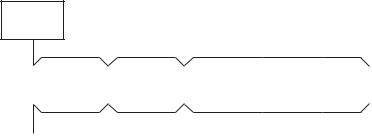
1-4-3 Group control
Max. 8 indoor units can be controlled by one remote controller on a group control.
Twin, triple control of 1 by 1 model (Toshiba Digital inverter, Super digital inverter) is one of group control. Header indoor unit controls indoor air temperature based on setting temperature of the remote controller.
<System sample>
Outdoor
unit
|
|
|
|
Header |
|
|
|
|
|||
|
|
|
|
|
|
|
|
|
|
|
|
|
Indoor |
|
|
Indoor |
|
|
Indoor |
|
Indoor |
|
|
|
unit |
1-1 |
unit |
1-2 |
|
unit |
1-3 |
unit |
1-8 |
||
|
|
|
|
|
|
|
|||||
|
|
|
|
|
|
|
|
|
|
|
|
|
|
|
|
|
|
|
|
|
|
Max. 8 units |
|
|
|
|
|
|
|
|
|
|
|
|
|
|
Remote |
|
|
|
|
|
|
|
|
|
|
|
|
|
|
|
|
|
|
|
|
||
|
controller |
|
|
[NOTE] |
Be sure to supply the power for all indoor units on the group control. |
||||||
|
|
|
|
|
|
|
|
If the power isn’t supplied to the header indoor unit, communication between indoor units |
|||
|
|
|
|
|
|
|
|
||||
|
|
|
|
|
|
|
|
and remote controller can’t be performed. |
|||
[1]Display range of remote controller
Remote controller reflects the setting range of header indoor unit. Setting range : Operation mode, Air Volume setting, Setting temperature
[ NOTE ] Don’t set the concealed duct high pressure type (AID-P***H, MMD-P***1H) to the header indoor unit.
 Set the other type indoor unit to the header indoor unit.
• In case concealed duct high static pressure type is the header indoor unit, display of remote controller is as follows. Operation mode : [AUTO] [HEAT] [COOL] [FAN], no [DRY] mode
Air volume selection : [HIGH]
• In case of [DRY] mode, duct type keeps [FAN] mode.
[ NOTE ] Don’t set cooling only model as header indoor unit.  Set heat pump model as header indoor unit.
• [AUTO] [HEAT] mode can’t be operated.
[2]Remote location control (HA)
Both header and follower indoor unit can response by remote location control (HA) signals. Master ON/OFF control can be conducted for all indoor units on the same group.
[ NOTE ] Don’t input two or more HA signals to one group.
[3]Address setting
All indoor units on the same group must be turned on when automatic address setting is conducted.
If power supply is turned on three minutes later than automatic address setting, reboot will occur and automatic address setting starts again.
[ NOTE.1 ] Be sure to do electrical work and control wiring certainly. [ NOTE.2 ] Reconfirm the line / indoor / group address one by one.
Especially confirm the identical line address both outdoor and indoor side.
12
1-4-4 Application controls for central remote controller
|
Basic function |
|
|
System diagram |
|
Model |
Reference |
|
|
|
|
|
N o . |
||||
|
|
|
|
|
|
|
|
|
|
|
|
Header |
Super MMS |
|
|
|
|
|
|
U3, U4 |
unit |
|
|
|
||
|
|
|
Outdoor unit |
|
|
|
||
|
|
|
|
|
|
|
||
|
|
|
|
Line-3 |
|
|
|
|
|
|
|
U5, U6 |
Indoor unit |
|
|
|
|
|
|
Zone |
U1, U2 |
|
|
|
|
|
|
|
|
|
|
|
|
|
|
|
|
4 |
|
|
|
|
|
|
|
|
|
Header |
Indoor remote controller |
|
|
|
|
|
|
|
unit |
|
|
|
|
|
|
|
U3, U4 |
|
|
Outdoor unit |
Super MMS |
|
|
|
|
|
|
|
|
|
||
|
|
|
U5, U6 |
Line-2 |
Indoor unit |
|
|
|
|
|
|
|
|
|
|||
|
|
Zone |
U1, U2 |
|
|
|
|
|
|
|
|
|
|
|
|
|
|
|
|
3 |
|
|
|
|
|
|
|
|
Zone |
|
|
|
|
|
|
|
|
2 |
|
|
|
|
|
|
|
|
|
Header |
Indoor remote controller |
|
|
|
|
|
|
|
unit |
|
|
|
|
|
|
|
U3, U4 |
Outdoor unit |
Super HRM |
|
|
|
|
|
|
|
Line-1 |
Indoor unit |
|
• Central remote |
|
|
|
|
Zone |
U1, U2 |
|
|
|
controller |
|
|
|
|
|
|
TCB-SC642TLE |
|
||
|
|
1 |
FS unit |
|
|
|
|
|
|
|
|
|
|
|
|
|
|
1 |
Central manage- |
Power |
Central |
Indoor remote controller |
|
|
|
|
ment controller |
|
<Indoor remote controller> |
|
|||||
|
|
|
|
|||||
|
for 64 units |
supply |
remote controller |
|
|
4-2 |
||
|
Single phase |
|
|
|
• Wired remote controller |
|||
|
|
220/230/240V |
|
|
|
|
||
|
|
|
|
|
|
|
RBC-AMT21E |
|
|
|
|
|
|
|
|
• Simple remote |
|
|
|
Function of central remote controller |
controller |
|
||||
|
|
• Individual control up to 64 indoor units. |
RBC-AS21E |
|
||||
|
|
|
|
|||||
•Individual control for max. 64 indoor units divided 1 to 4 zone. (Up to 16 indoor units for each zone.)
•Up to 16 outdoor header units are connectable.
•4 type central control setting to inhibit individual operation by remote controller can be selected.
•Setting for one of 1 to 4 zone is available.
•Usable with other central control devices
(Up to 10 central control devices in one control circuit)
• Two control mode selectivity
Central controller mode/Remote controller mode
• Setting of simultaneous ON/OFF 3 times for each day of the week combined with weekly timer.
|
|
|
|
|
|
|
|
|
|
|
|
|
|
|
|
|
|
|
|
|
|
|
|
• Central remote |
|
|
|
|
|
|
|
|
|
|
|
|
|
|
|
|
|
|
|
|
|
|
|
|
controller |
|
Central remote |
|
U3, U4 |
|
|
Outdoor unit |
Super MMS |
|
|
|
|
|
|
|
TCB-SC642TLE |
|||||||||
|
|
|
|
|
|
|
Indoor unit |
U1, U2 |
+ |
|||||||||||||||
|
controller |
|
|
|
|
|
|
|||||||||||||||||
|
|
|
|
|
|
|
|
|
|
|
|
|
|
|
|
|
|
|
• Weekly timer |
|||||
|
|
+ |
|
|
|
|
|
|
|
|
|
|
|
|
|
|
|
|
|
|
|
|
|
|
|
Weekly timer |
|
|
|
|
|
|
|
|
|
|
|
|
|
|
|
|
|
|
|
|
|
RBC-EXW21E |
|
|
|
|
|
|
|
|
|
|
|
|
|
|
|
|
|
|
|
|
|
|
|
|
||
2 |
|
Weekly |
|
|
|
|
|
|
|
|
|
|
|
|
|
|
|
|
|
|
|
4-2 |
||
|
|
|
|
|
|
|
|
|
|
|
|
|
|
|
|
|
||||||||
|
|
operation |
|
|
|
|
Indoor remote controller |
|
|
|
|
|
|
|
<Indoor remote controller> |
|||||||||
|
|
|
|
|
|
|
|
|
|
|
|
|
|
|||||||||||
|
|
schedule |
|
Single phase |
|
|
|
|
|
|
|
|
|
|
|
|
|
|
|
|
|
• Wired remote controller |
||
|
|
can be set by |
|
|
|
|
|
|
|
|
|
|
|
|
|
|
|
|
|
|
RBC-AMT21E |
|||
|
|
connecting a |
|
220/230/240V |
|
|
|
|
|
|
|
|
|
|
|
|
|
|
|
|
|
|
||
|
Power |
|
|
|
|
|
|
|
|
|
|
|
|
|
|
|
|
|
|
|
or |
|||
|
|
weekly timer |
|
|
|
|
|
Weekly timer |
|
|
|
|
|
|
|
|||||||||
|
supply |
|
|
|
|
|
|
|
|
|
|
|
• Simple remote |
|||||||||||
|
|
to the central |
|
Central |
|
|
|
|
|
|
|
|
|
|
|
|
|
|
|
|
|
|||
|
|
remote |
|
remote controller |
|
|
|
|
|
|
|
controller |
||||||||||||
|
|
|
|
|
|
|
|
|
|
|
|
|
|
|
|
|
|
|
|
|
|
|
RBC-AS21E |
|
|
|
controller |
|
|
|
|
|
|
|
|
|
|
|
|
|
|
|
|
|
|
|
|
|
|
|
|
|
|
|
|
|
|
|
|
|
|
|
|
|
|
|
|
|
|
|
|
|||
13

|
Basic function |
|
|
|
System diagram |
|
|
|
|
|
|
Model |
Reference |
||||||||||
|
|
|
|
|
|
|
|
|
|
N o . |
|||||||||||||
|
|
|
|
|
|
|
|
|
|
|
|
|
|
|
|
|
|
|
|
|
|
|
|
|
|
|
|
|
|
|
|
|
|
|
|
|
|
|
|
|
|
|
|
|
|
|
|
|
|
|
|
|
|
U3, U4 |
|
Outdoor unit |
|
|
|
|
|
|
|
|
|||||||
|
|
|
|
|
|
|
|
|
|
|
|
|
|
|
|||||||||
|
|
|
|
|
|
|
|
|
|
|
|
|
|
|
|
|
|
||||||
|
|
|
|
|
|
|
|
|
|
|
|
|
|
|
|
U1, U2 |
|
|
|
||||
|
|
|
|
|
|
|
|
|
|
|
|
|
|
|
|
|
|
|
|
|
|
|
|
|
|
|
|
|
|
|
|
|
|
|
|
|
|
|
|
|
|
|
|
|
|
|
|
|
|
|
|
Power |
|
|
|
|
|
|
|
|
Indoor unit |
|
|
|
|||||||
|
|
|
|
supply |
|
|
|
Central remote controller |
|
|
|
|
|
|
|
|
|||||||
|
|
Single phase |
|
|
|
|
|
|
|
|
|
|
|||||||||||
|
|
|
|
|
|
|
|
|
|
|
|
|
|
|
|
|
|
|
|
||||
|
|
220/230/240V |
|
|
|
Even when grouping operation is performed |
|
|
|
||||||||||||||
|
|
|
|
|
|
|
|
|
|
|
|
||||||||||||
|
|
|
|
|
|
|
|
|
by connecting multiple indoor units to 1 line, |
|
• Central remote |
|
|||||||||||
|
|
|
|
|
|
|
|
|
the indoor remote controller is required. |
|
|
||||||||||||
|
|
|
|
Example of grouping operation |
|
|
|
|
|
|
controller |
|
|||||||||||
|
|
|
|
|
|
|
|
|
|
|
|||||||||||||
|
|
|
|
|
|
|
|
|
|
|
|
|
|
|
|
|
|
|
|
|
|
TCB-SC642TLE |
|
|
Remote central |
U3, U4 |
|
|
|
|
|
|
|
|
|
|
|
|
|
|
|||||||
|
|
Outdoor unit |
|
|
|
|
|
|
|
|
|||||||||||||
3 |
control without |
|
|
|
|
|
|
|
|
|
|
|
|
||||||||||
|
|
|
|
U1, U2 |
|
|
|
|
|
|
|
4-2 |
|||||||||||
|
indoor remote |
|
|
|
|
|
|
|
|
|
|
|
|
|
|
|
|
<Indoor remote |
|||||
|
controller |
|
|
|
|
|
|
|
|
|
|
|
|
|
|
|
|
controller> |
|
||||
|
|
|
|
|
|
|
|
|
|
(Group) |
|
|
|
|
|
|
• Wired remote |
|
|||||
|
|
|
|
Power |
|
|
|
|
|
|
|
|
|
|
controller |
|
|||||||
|
|
|
|
|
|
Indoor remote controller |
Available |
|
|
||||||||||||||
|
|
|
|
supply |
|
|
|
is required |
|
RBC-AMT21E |
|
||||||||||||
|
|
|
|
|
|
||||||||||||||||||
|
|
Single phase |
|
Central remote controller |
|
|
|
|
|
|
|
|
|||||||||||
|
|
220/230/240V |
|
|
|
|
|
|
|
|
|
|
|
|
|
|
|
|
|
|
|||
U3, U4
Outdoor unit
U1, U2
Power |
|
(Group) |
|
|
Available |
||
supply |
|
|
|
|
|
||
|
|
|
|
Single phase |
Central remote controller |
||
220/230/240V |
|
|
|
|
|
|
|
|
|
|
|
|
|
|
|
|
|
|
|
|
|
|
• Central remote |
|
|
|
Power |
|
Central remote controller |
|
|
|
|
|
|
|
|
controller |
|
||||||||
|
|
|
|
|
|
|
|
|
|
|
|||||||||||
|
|
|
|
|
|
|
|
|
|
TCB-SC642TLE |
|
||||||||||
|
supply |
|
|
|
|
|
|
|
|
|
|
|
|
|
|
|
|
|
|
|
|
|
|
|
|
|
|
|
|
|
|
|
|
|
|
|
|
|
|
|
|
||
|
U3, U4 |
|
|
|
|
|
|
|
|
|
|
|
|
|
|
|
|
• “1 : 1 model” |
|
||
|
|
|
|
|
|
|
|
|
|
|
|
|
|
|
|
|
|
connection |
|
||
4 Central manage- |
|
|
|
|
|
|
|
|
|
|
|
|
|
|
|
|
|
|
|
4-2 |
|
|
|
|
|
|
|
|
|
|
|
|
|
|
|
|
|
|
|
|
interface |
||
ment control with |
Header |
|
Super MMS |
|
|
|
|
|
* |
1 |
TCB-PCNT30TLE |
|
|||||||||
“1 : 1 model” |
unit |
|
|
|
|
|
|
|
|||||||||||||
|
|
|
|
|
|
|
|
|
|
|
|
|
|
|
|
|
|
|
|||
|
|
|
|
|
|
|
|
|
|
|
|
|
|
|
|
|
|
|
|||
|
|
|
|
|
|
|
|
|
|
|
|
|
|
|
|
|
|
|
|
||
|
|
|
|
|
|
|
|
|
|
|
|
|
|
|
|
|
|
|
|
RAV-SM560KRT-E, |
|
|
U1, U2 |
|
|
Indoor unit |
"1:1 model" |
|
|
|
SM800KRT-E are |
|
|||||||||||
|
|
|
|
|
connection |
|
|
|
|
|
|
not available |
|
||||||||
|
|
|
|
|
|
|
|
|
|
|
|
|
|
|
|
|
|||||
|
|
|
|
|
|
|
|
|
|
|
|
interface |
|
|
|
|
|
<Indoor remote |
|
||
|
|
|
|
|
|
|
|
|
|
|
|
|
|
|
|
|
|
|
|
|
|
|
|
|
|
|
|
|
|
|
|
|
|
|
|
|
|
|
|
|
|
|
|
|
|
Indoor remote controller |
|
|
|
|
|
|
|
|
controller> |
|
|||||||||
|
|
|
|
|
|
|
|
|
• Wired remote |
|
|||||||||||
|
|
|
|
|
|
|
|
|
|
|
|
|
|
|
|
|
|
|
|
||
|
|
|
|
|
|
|
|
|
|
|
|
|
|
|
|
|
|
|
|
controller |
|
|
|
|
|
|
|
|
|
|
|
|
|
|
|
|
|
|
|
|
|
RBC-AMT21E |
|
|
|
|
|
|
|
|
|
|
|
|
|
|
|
|
|
|
|
|
• Simple remote |
|
|
|
|
|
|
|
|
|
|
|
|
|
|
|
|
|
|
|
|
|
|
controller |
|
|
|
|
|
|
|
|
|
|
|
|
|
|
|
|
|
|
|
|
|
RBC-AS21E |
|
*TOSHIBA Digital Inverter System and Super Digital Inverter System
14
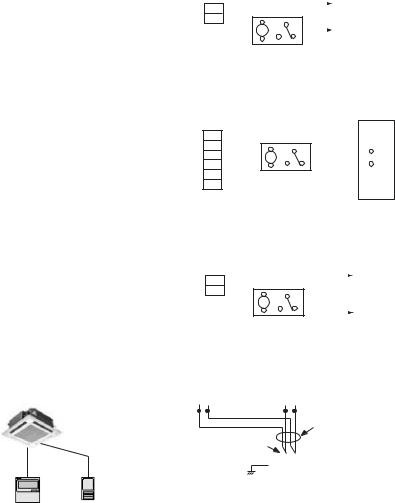
1-5 Application controls of indoor unit
No |
Control name |
|
|
|
|
|
|
|
|
|
|
|
|
|
|
|
Function |
|
Reference No. |
|||||||||||||||||
|
|
|
|
|
|
|
|
|
|
|
|
|
|
|
|
|
|
|
|
|
|
|
|
|
|
|
|
|
|
|
|
|
|
|
|
|
|
Function change |
|
Items necessary to perform the applied control at the |
Item code (DN) |
|
|||||||||||||||||||||||||||||||
1 |
|
|
local site can be selected. |
|
|
|
|
|
|
|
|
|
|
|
|
setting from wired |
4-3-1 |
|||||||||||||||||||
|
|
(Ex. Setup of TA sensor, body TA sensor / remote |
remote controller |
|||||||||||||||||||||||||||||||||
|
|
|
|
|||||||||||||||||||||||||||||||||
|
|
|
controller sensor) |
|
|
|
|
|
|
|
|
|
|
|
|
|
|
|||||||||||||||||||
|
|
|
|
|
|
|
|
|
|
|
|
|
|
|
|
|
|
|
|
|
|
|
|
|
|
|
|
|
|
|
|
|
|
|
|
|
|
Ventilation fan control |
|
ON/OFF control can be operated from wired remote |
Setting from wired |
|
|||||||||||||||||||||||||||||||
|
from remote controller |
|
controller when the entire heat exchanger or |
remote controller |
|
|||||||||||||||||||||||||||||||
|
|
|
ventilation fan is installed in the system. |
+ |
|
|||||||||||||||||||||||||||||||
|
|
|
|
|
|
|
|
|
|
|
|
|
Relay (DC12V, procured locally) |
Relay wiring |
|
|||||||||||||||||||||
2 |
|
|
CN32 |
|
|
1 |
1 |
|
|
|
|
|
|
|
|
|
|
|
|
|
|
|
|
|
|
Outside control |
(local supply) |
4-3-2 |
||||||||
|
|
|
FAN DRIVE |
|
|
|
|
|
|
|
|
|
|
|
|
|
|
|
|
|
|
|
input of fan |
|
||||||||||||
|
|
|
(2P WHI) |
|
2 |
2 |
|
|
|
|
|
|
|
|
|
|
|
|
|
|
|
|
|
|
To terminal |
|
|
|||||||||
|
|
|
|
|
|
|
|
|
|
|
|
|
|
|
|
|
|
|
|
|
|
|
||||||||||||||
|
|
|
|
|
|
|
|
|
|
|
|
|
|
|
|
|
|
|
|
|
|
|
|
|
|
|
|
|
|
|||||||
|
|
|
Indoor control |
|
|
|
|
|
|
|
|
|
|
|
|
|
|
|
|
|
|
|
|
|||||||||||||
|
|
|
|
|
|
|
|
|
|
|
|
|
|
|
|
|
|
|
|
|
|
|
|
|||||||||||||
|
|
|
P.C.board |
|
|
|
|
|
|
|
|
|
|
|
|
|
|
|
|
|
|
|
|
|||||||||||||
|
|
|
|
|
|
|
|
|
|
|
|
|
|
|
|
|
|
|||||||||||||||||||
|
|
|
|
|
|
|
|
|
|
|
|
|
|
|
|
|
|
|
|
|
|
|
||||||||||||||
|
|
|
|
|
|
|
|
|
|
|
|
|
|
|
|
|
|
|
|
|
|
|
|
|
|
|
|
|
|
|
|
|
|
|
|
|
|
Leaving-ON prevention |
|
Using a card switch box, card lock etc, the leaving- |
Setting from wired |
|
|||||||||||||||||||||||||||||||
|
control |
|
ON of the indoor unit can be prevented by setting of |
remote controller |
|
|||||||||||||||||||||||||||||||
|
|
|
remote controller and relay wiring. |
+ |
|
|||||||||||||||||||||||||||||||
|
|
|
|
|
|
|
|
|
|
|
|
|
|
|
|
|
Relay (procured locally) |
Relay wiring |
|
|||||||||||||||||
|
|
|
CN61 |
1 |
|
1 |
|
|
|
|
|
|
|
|
|
|
|
|
|
|
|
|
|
|
|
|
|
|
(local supply) |
|
||||||
|
|
|
|
T10 |
|
|
|
|
|
|
|
|
|
|
|
|
|
|
|
|
|
|
|
|
|
|
|
|
|
|||||||
3 |
|
|
(YEL) |
2 |
|
2 |
|
|
|
|
|
|
|
|
|
|
|
|
|
|
|
|
|
|
|
|
|
|
|
4-3-3 |
||||||
|
|
3 |
|
3 |
|
|
|
|
|
|
|
|
|
|
|
|
|
|
|
|
|
|
|
|
|
|
|
|||||||||
|
|
|
|
|
|
|
|
4 |
|
4 |
|
|
|
|
|
|
|
|
|
|
|
|
|
|
|
|
|
|
|
|
|
|
|
|
||
|
|
|
|
|
|
|
|
5 |
|
5 |
|
|
|
|
|
|
|
|
|
|
|
|
|
|
|
|
|
|
|
|
|
|
|
|
||
|
|
|
|
|
|
|
|
6 |
|
6 |
|
|
|
|
|
|
|
|
|
|
|
|
|
|
|
|
|
|
|
|
|
|
|
|
||
|
|
|
Indoor control |
|
|
|
|
|
|
|
|
|
|
|
|
|
|
|
|
|
|
|
|
|
|
|
|
|
|
|
||||||
|
|
|
|
|
|
|
|
|
|
|
|
|
|
|
|
|
|
Power supply |
|
|
||||||||||||||||
|
|
|
P.C.board |
|
|
|
|
|
|
|
|
|
|
|
|
|
|
|
|
|
|
|
||||||||||||||
|
|
|
|
|
|
|
|
|
|
|
|
|
|
|
|
|
|
|
|
|
|
|
|
|
|
|
Outside contact |
|
|
|||||||
|
|
|
|
|
|
|
|
|
|
|
|
|
|
|
|
|
|
|
|
|
|
|
|
|
|
|
|
|
|
|
|
|
|
|
|
|
|
Demand control |
|
Thermostat-OFF operation by relay signal. |
Relay wiring |
|
|||||||||||||||||||||||||||||||
|
|
|
• Wiring example |
|
|
|
|
|
|
|
|
|
|
|
|
(local supply) |
|
|||||||||||||||||||
|
|
|
|
|
|
|
|
|
|
|
|
|
|
|
|
|
|
|
|
|
|
|
|
|
|
Relay (procured locally) |
|
|
||||||||
4 |
|
|
|
CN73 |
1 |
1 |
|
|
|
|
|
|
|
|
|
|
|
|
|
4-3-4 |
||||||||||||||||
|
|
|
|
|
|
|
|
|
|
|
|
|
|
|
|
|
|
|
|
|
|
|
|
|
||||||||||||
|
|
|
|
|
|
|
|
|
|
|
|
|
|
|
|
|
|
|
|
|
|
|
|
|
|
|
|
|
||||||||
|
|
|
|
|
|
|
2 |
2 |
|
|
|
|
|
|
|
|
|
|
|
|
|
|
|
Relay coil signal |
|
|||||||||||
|
|
|
|
|
EXCT |
|
|
|
|
|
|
|
|
|
|
|
|
|
|
|
|
|
|
|
||||||||||||
|
|
|
|
|
|
|
|
|
|
|
|
|
|
|
|
|
|
|
|
|
|
|
||||||||||||||
|
|
|
(2P plug: RED) |
|
|
|
|
|
|
|
|
|
|
|
|
|
|
|
|
|
|
|
|
|
|
|
|
|
||||||||
|
|
|
|
|
|
|
|
|
|
|
|
|
|
|
|
|
|
|
|
|
|
|
||||||||||||||
|
|
|
|
|
|
|
|
|
|
|
|
|
|
|
|
|
|
|
|
|
||||||||||||||||
|
|
|
Indoor control |
|
|
|
|
|
|
|
|
|
|
|
|
|
|
|
|
|
|
|||||||||||||||
|
|
|
|
|
|
|
|
|
|
|
|
|
|
|
|
|
|
|||||||||||||||||||
|
|
|
P.C.board |
|
|
|
|
|
|
|
|
|
|
|
|
|
|
|||||||||||||||||||
|
|
|
|
|
|
|
|
|
|
|
|
|
|
|
|
|
|
|
|
|
|
|
|
|
|
|
|
|
|
|
|
|
|
|
|
|
|
Remote sensor |
|
Air temperature sensing at a distance. |
Remote sensor |
|
|||||||||||||||||||||||||||||||
|
(TCB-TC21LE) |
|
Remote |
|
|
|
|
|
|
|
|
|
|
|
|
Remote |
|
|
|
|
|
|
|
(Sold |
(TCB-TC21LE) |
|
||||||||||
|
|
|
|
|
|
|
|
|
|
|
|
|
|
|
|
|
|
|
|
|
|
|
|
|||||||||||||
|
|
|
sensor |
|
|
|
|
|
|
|
|
|
|
|
|
controller |
|
|
|
|
|
|
|
separately) |
|
|
||||||||||
|
|
|
|
|
|
|
|
|
|
|
|
|
|
|
|
|
(Master) |
|
|
|
|
|
|
|
|
|
|
|
|
|
|
|
|
|||
|
|
|
|
|
|
|
|
|
|
|
|
|
|
|
|
|
|
|
Remote controller cable |
|
|
|||||||||||||||
|
|
|
|
|
|
|
|
|
|
|
|
|
|
|
|
|
|
|
|
|
|
|
|
|
|
|
|
|
||||||||
|
Indoor |
|
|
|
|
|
|
|
|
|
|
|
|
|
|
|
|
|
|
|
|
|
|
|
|
|
(Procured locally) |
|
|
|||||||
|
|
Terminal block for |
|
|
|
|
|
|
|
|
|
|
|
|
|
|
||||||||||||||||||||
|
Unit |
|
|
|
|
|
|
|
|
|
|
|
|
|
|
4-3-5 |
||||||||||||||||||||
5 |
|
|
remote controller cable |
|
|
|
|
|
|
|
|
|
|
|
|
|
||||||||||||||||||||
|
|
|
|
|
|
|
|
|
|
|
|
|
|
|
|
|
|
|
|
|
|
|
|
|
|
|
|
|
|
|
|
|
|
|
|
|
|
|
|
|
|
|
|
|
|
|
|
|
|
|
|
|
|
|
|
|
|
|
|
A |
B |
|
|
|
|
|
|
|
|
|
|||
|
|
|
|
|
|
|
|
|
|
|
|
|
|
|
|
|
Earth |
Indoor unit |
|
|
|
|
|
|
|
|
||||||||||
|
|
|
|
|
|
|
|
|
|
|
|
|
|
|
|
|
|
|
|
|
|
|
|
|
|
|
|
|
|
|
|
|
|
|||
|
Remote |
Remote |
[NOTE] |
|
|
|
|
|
|
|
|
|
|
|
|
|
|
|
|
|
|
|
|
|
|
|
|
|
|
|
|
|
||||
|
Controller |
Sensor |
|
|
|
|
|
|
|
|
|
|
|
|
|
|
|
|
|
|
|
|
|
|
|
|
|
|
|
|
|
|||||
|
|
|
Don’t change TA sensor to remote controller sensor |
|
|
|||||||||||||||||||||||||||||||
|
|
|
by item code (DN) setting. |
|
|
|
|
|
|
|
|
|
|
|
|
|
|
|||||||||||||||||||
|
|
|
|
|
|
|
|
|
|
|
|
|
|
|
|
|
|
|
|
|
|
|
|
|
|
|
|
|
|
|
|
|
|
|
|
|
1-6 Application controls of outdoor unit
No |
Control name |
Function |
Setting method |
Reference No. |
|
|
|
|
|
|
|
1 |
Outdoor fan high static |
Increase outdoor fan speed so that a duct with the |
Switch setting on |
4-4-1 |
|
pressure shift |
maximum outside static pressure 35Pa can be installed. |
||||
|
outdoor interface |
|
|||
|
|
|
|
||
|
Cooling priority, heating |
Cooling priority or heating priority can be selected. |
4-4-2 |
||
2 |
P.C. board |
||||
priority control |
(Setup at shipment : heating priority) |
||||
|
|
|
|||
|
|
|
|
|
|
|
Specific indoor unit |
Only one indoor unit can be set to priority for changeover |
Switch setting on |
|
|
|
priority control |
operation mode. |
|
||
|
outdoor interface |
|
|||
|
|
|
|
||
|
|
|
P.C. board |
4-4-3 |
|
3 |
|
|
+ |
||
|
|
Item code (DN) |
|
||
|
|
|
|
||
|
|
|
setting from wired |
|
|
|
|
|
remote controller |
|
|
|
|
|
|
|
15
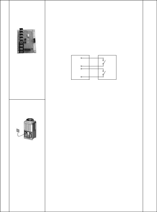
1-7 Application controls by optional P.C. board of outdoor unit
Model |
Appearance |
Function |
Reference |
|
name |
No. |
|||
|
|
|||
|
|
[1] Power peak-cut Control |
|
●Feature
The upper limit capacity of the outdoor unit is restricted based on the power peak cut request signal from outside.
●Function
Two type control can be selected by setting SW07 on the interface P.C. board of the header outdoor unit.
TCB-PCDM2E |
Local Supply |
ON
Size : 71 x 85 (mm)
SW1
COM
OFF
SW2
COM
|
Application |
[Standard function] |
|
|
|
|
||
|
SW07-2 OFF |
|
|
|
|
|||
|
|
|
|
|
|
|
||
PCDM2E |
|
|
|
|
|
4-5-1 |
||
ON |
OFF |
0% (stop) |
Up to 60% |
|||||
|
|
|
Input |
|
SW07-1 |
|||
|
|
|
SW01 |
|
SW02 |
OFF |
ON |
|
- |
|
|
|
|
|
|
|
|
TCB |
OFF |
|
ON |
100% (Normal) |
100% (Normal) |
|
||
|
|
|
|
|
||||
|
|
|
|
|
|
|
|
|
|
|
|
[Expansion function] |
|
|
|
|
|
|
|
|
SW07-2 ON |
|
|
|
|
|
|
|
|
|
|
|
|
|
|
|
|
|
Input |
|
SW07-1 |
|
||
|
|
|
|
|
|
|
|
|
|
|
|
SW01 |
|
SW02 |
OFF |
ON |
|
|
|
|
|
|
|
|
|
|
|
* Place this optional P.C. |
OFF |
|
OFF |
100% (Normal) |
100% (Normal) |
|
|
|
board to inverter |
ON |
|
OFF |
Up to 80% |
Up to 85% |
|
|
|
assembly of the header |
|
|
|
|
|
|
|
OFF |
|
ON |
Up to 60% |
Up to 75% |
|
|||
|
outdoor unit. |
|
|
|||||
|
|
|
|
|
|
|
||
ON |
|
ON |
0% (stop) |
Up to 60% |
|
|||
|
|
|
|
|
||||
|
|
|
|
|
|
|
|
|
•Be sure to prepare the point of contact for each terminal.
•Don’t turn on both SW1 and SW2 terminal simultaneously.
16
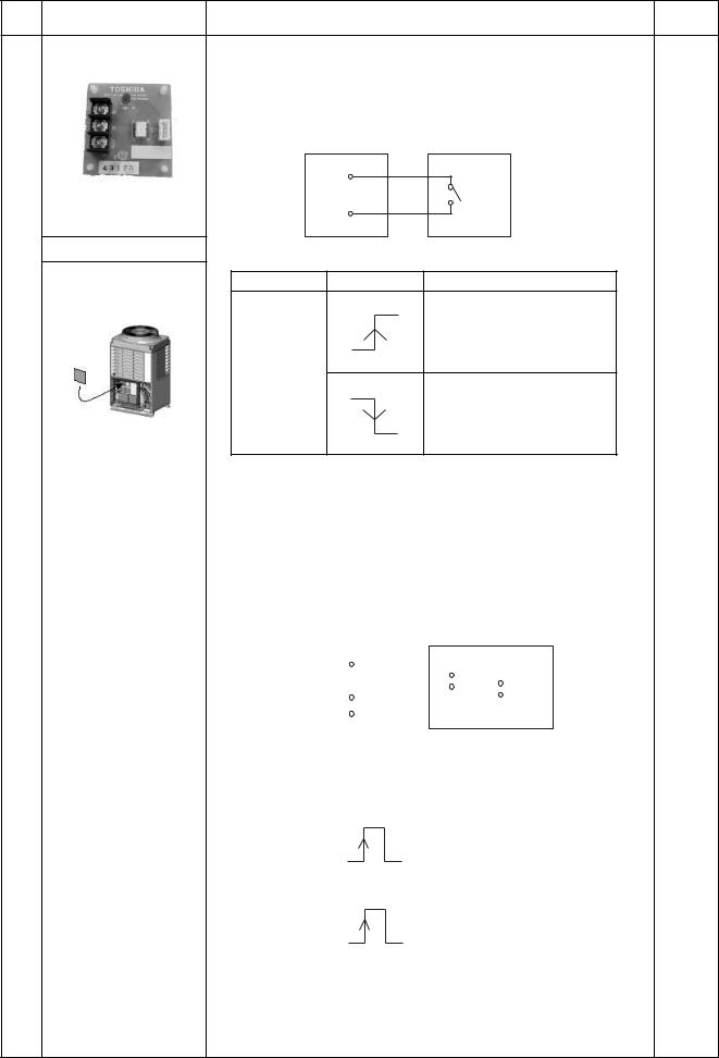
Model |
Appearance |
Function |
Reference |
|
name |
No. |
|||
|
|
[2] Snowfall fan control
●Feature
Outdoor fan is operated with the snowfall signal from outside.
●Function
TCB-PCMO2E |
Local Supply |
COM
SMC
Size : 55.5 x 60 (mm) |
Cooling |
Application |
SMC : Cooling mode select input (switch) |
||
|
|||
|
Terminal |
Input signal |
4-5-2 |
|
Operation |
||
|
|
ON |
|
|
|
|
Snowfall fan control |
|
|
|
(Operates outdoor fan.) |
|
|
OFF |
|
|
SMC |
|
|
|
|
ON |
|
|
|
|
Usual operation |
|
|
|
(Releases control) |
|
|
OFF |
|
PCMO2E- |
* Place this optional P.C. |
This control is conducted when input signal stand up and fall down. |
|
board to inverter |
(Standing and falling status should be held for 100 mm.sec. or more.) |
||
|
|||
|
assembly of the header |
|
|
|
outdoor unit. |
|
|
|
|
TCB |
[3] External master ON/OFF control |
|
||||||||||||
● Feature |
|
|
|
|
|
|
|
|
|
|
|
|
||
|
|
|
|
|
|
|
|
|
|
|
|
|
||
|
|
The outdoor unit starts or stops the system. |
|
|||||||||||
|
● Function |
|
|
|
|
|
|
|
|
|
|
|
|
|
|
|
|
TCB-PCMO2E |
|
|
Local Supply |
|
|||||||
|
|
|
|
|
|
|
|
|
|
|
|
|
|
|
|
|
|
COM |
|
|
|
|
|
|
|
|
|
|
|
|
|
|
Cooling |
|
|
|
|
SMC |
|
|
SMH |
|
||
|
|
|
|
|
|
|
|
|||||||
|
|
|
|
|
|
|
|
|
|
|
||||
|
|
|
|
|
|
|
||||||||
|
|
|
|
|
|
|
|
|
|
|
|
|
||
|
|
|
Heating |
|
|
|
|
|
|
|
|
|
|
|
|
|
|
|
|
|
|
|
|
|
|
|
|
||
|
|
|
|
|
|
|
|
|
|
|
|
|
|
|
|
|
SMC : Input signal for start |
|
|
|
|
|
|
|
|
||||
|
|
SMH : Input signal for stop |
|
|
|
|
|
|
|
4-5-3 |
||||
|
|
|
|
|
|
|
|
|
|
|
|
|
|
|
|
|
Terminal |
|
Input signal |
|
|
Operation |
|
||||||
|
|
|
|
|
|
|
||||||||
|
|
|
|
|
|
|
|
|
|
|
|
|
|
|
|
|
|
|
ON |
|
|
|
|
|
|
|
|
||
|
|
SMC |
|
|
|
|
Starts all indoor units. |
|
|
|||||
|
|
|
|
|
OFF |
|
|
|
|
|
|
|
|
|
|
|
|
|
|
|
|
|
|
|
|
|
|
|
|
|
|
|
|
ON |
|
|
|
|
|
|
|
|
||
|
|
SMH |
|
|
|
|
Stops all indoor units. |
|
|
|||||
|
|
|
|
OFF |
|
|
|
|
|
|
|
|
||
|
|
|
|
|
|
|
|
|
|
|
|
|
|
|
|
|
• Be sure to prepare non voltage continuous point of contact for each terminal. |
|
|||||||||||
This control is conducted when input signal stand up or fall down. (Standing and falling status should be held for 100 mm.sec. or more.)
17
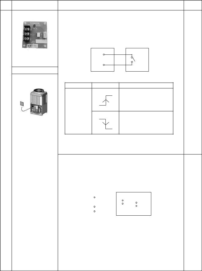
Model |
Appearance |
Function |
Reference |
|
name |
No. |
|||
|
|
[4] Night operation (Sound reduction) control
●Feature
Sound level can be reduced with connecting outdoor E-parts by restricting compressor and fan speed.
●Function
TCB-PCMO2E |
Local Supply |
COM |
|
Size : 55.5 x 60 (mm) |
SMC |
Cooling
|
Application |
|
|
|
|
|
|
SMC : Cooling mode designated input switch |
|||
|
|
Terminal |
Input signal |
4-5-4 |
|
|
|
Operation |
|||
|
|
|
ON |
|
|
|
|
|
|
Night operation (sound reduction) |
|
|
|
|
|
control |
|
|
|
SMC |
OFF |
|
|
|
|
|
|
||
|
|
|
ON |
|
|
|
|
|
|
Usual Operation |
|
|
|
|
OFF |
|
|
PCMO2E-TCB |
* Place this optional P.C. |
[5] Operation mode selection control |
|||
board to inverter |
|||||
|
This control is conducted when input signal stand up or fall down. |
||||
|
assembly of the header |
||||
|
(Standing and falling status should be held for 100 mm.sec or more.) |
||||
|
outdoor unit. |
||||
|
|
|
|
||
●Feature
This control can be operated with the operation mode which is permitted by SMC or SMH.
●Function
|
|
TCB-PCMO1E |
|
|
Local Supply |
|||||||
|
|
COM |
|
|
|
|
|
|
|
|
|
|
|
|
Cooling |
|
|
|
|
SMC |
|
|
SMH |
||
|
|
|
|
|
|
|||||||
|
|
|
|
|
|
|
|
|
||||
|
|
|
|
|
||||||||
|
|
|
|
|
|
|
|
|
|
|
||
|
|
Heating |
|
|
|
|
|
|
|
|
|
|
|
|
|
|
4-5-5 |
||||||||
|
|
|
|
|
|
|||||||
SMC : Cooling mode designated input switch |
||||||||||||
SMH : Heating mode designated input switch |
||||||||||||
|
|
|
|
|
|
|
|
|
|
|
|
|
SMC |
|
|
SMH |
|
|
Selected operation mode |
|
|||||
|
|
|
|
|
|
|
|
|
|
|
|
|
ON |
|
|
OFF |
Only cooling mode |
|
|||||||
|
|
|
|
|
|
permitted |
|
|||||
|
|
|
|
|
|
|
|
|
|
|
|
|
OFF |
|
|
ON |
Only heating mode |
|
|||||||
|
|
|
|
|
|
permitted |
|
|||||
|
|
|
|
|
|
|
|
|
|
|
|
|
Be sure to prepare non-voltage continuous point of contact for each terminal.
18
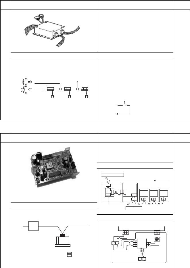
1-8 Application controls by optional devices connected to indoor unit
[1] Remote location ON/OFF control box
Model
name
TCB-IFCB-4E
Appearance |
Features |
Reference |
|
No. |
|||
|
|
||
|
● Start and stop of air conditioner is possible by the |
|
|
|
external signal, and also indication of operation/ |
|
|
|
alarm to outside is possible. |
|
Application |
Function |
|
4-6-1 |
|
• Monitoring |
|
ON/OFF status (for indoor unit) |
Operation |
Alarm status (system & indoor unit stop) |
• ON/OFF command |
|
|
Air conditioner can be turned ON/OFF by the |
|
external signals. |
|
The external ON/OFF signals are output for the |
|
signals below. |
Interface |
|
Display |
|
Remote |
|
Controller |
ON/OFF |
|
Non-voltage |
|
ON /OFF continuous signal |
|
COM |
[2] Network adapter
Model
name
TCB-PCNT20E
Appearance |
Features |
Reference |
|
No. |
|||
|
|
||
|
● Indoor units of VRF system is controlled by AI- |
|
|
|
NETWORK central remote controller. |
|
|
|
Connectable indoor units per group. |
|
|
|
|
Connection of cables |
|
||||||||
|
|
Central remote controller |
|
|
|
|
|
|
|
|||
|
|
|
|
|
|
|
|
Non polarity cable |
|
|||
|
|
X Y |
|
|
|
Indoor unit |
|
|
|
|
||
|
|
CN03 |
|
|
|
|
control |
Indoor unit |
Indoor unit |
Indoor unit |
||
|
|
1 2 |
1 |
1 |
1 |
P.C.board |
Indoor |
|
Indoor |
Indoor |
||
|
|
|
|
CN041 |
|
|||||||
Place optional P.C. board in E-parts of indoor unit. |
|
2 |
3 |
3 |
|
|
||||||
1 3 |
|
1 3 |
control |
|
control |
control |
||||||
|
|
CN309 |
P.C.board |
P.C.board |
P.C.board |
|||||||
|
|
|
|
|
|
|
||||||
|
|
CN02 |
CN01 |
|
Indoor |
A B |
A B |
|
A B |
A B |
||
|
|
|
|
|
unit |
|
||||||
|
|
|
|
|
|
|
|
|
|
4-6-2 |
||
|
Application |
Non polarity cable |
|
|
|
|
|
|
||||
|
Remote controller |
|
|
|
||||||||
|
|
|
|
|
|
|
|
|
||||
Power |
|
Wiring diagram of indoor P.C. board |
||||||||||
|
|
|
|
|
|
|
|
|
|
|
|
|
Supply |
Al Network |
|
|
|
|
|
|
|
|
|
|
|
|
|
|
|
CN040(Blue) Indoor control P.C.board CN300(Yellow) |
||||||||
|
|
|
|
1 2 3 |
|
|
|
|
1 |
3 |
||
Central Remote |
Network Adapter |
|
|
1 2 3 |
|
|
|
|
1 |
3 |
||
|
|
Black |
|
Black |
|
|
|
|
|
|||
Controller |
|
|
|
|
|
|
|
|
||||
|
Terminal block |
|
|
|
|
|
|
|
|
|
||
TCB-SC641E |
|
for connecting |
|
|
|
|
|
Network |
|
|
|
|
|
remote controller |
|
|
|
Black |
3 3 |
CN01(White) |
|
||||
|
|
|
|
|
adapter |
Power |
||||||
|
|
|
A B |
|
|
|
|
2 2 |
P.C. board |
2 2 |
||
|
|
|
|
|
|
|
Supply |
|||||
|
|
|
|
|
|
|
White |
1 1 CN02(Blue) |
1 1 |
transformer |
||
|
|
|
|
|
|
|
|
|
CN03(Red) |
|
|
|
|
Indoor unit |
|
|
|
|
|
|
|
1 2 |
|
|
|
|
Remote |
|
|
|
|
|
|
|
1 2 |
|
|
|
|
|
|
|
|
|
|
|
Gray Gray |
|
|
||
|
Controller |
|
|
|
|
|
|
|
|
|
|
|
|
|
|
|
|
|
|
|
|
X Y |
|
|
|
|
|
|
|
|
|
Network connection terminal block |
|
|||||
19
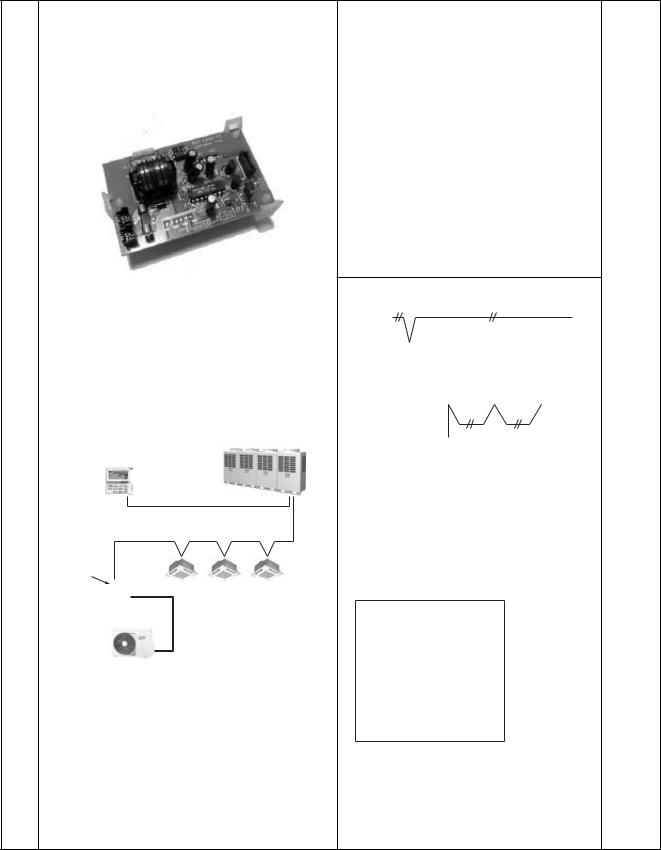
[3] “1:1 model” connection interface
Model |
Appearance |
Features |
Reference |
|
name |
No. |
|||
|
|
|||
|
|
● Link adapter for “1:1 model” into VRF system |
|
|
|
|
network |
|
|
|
|
1:1 model : Super digital inverter |
|
|
|
|
Digital inverter |
|
|
Place optional P.C. board in E-parts of indoor unit. |
|
|
|
|
|
|
|
Connection of cables |
||||||||||||||||||||||||||||||||||||||||||
|
|
|
|
|
|
|
|
|
|
|
|
|
|
|
|
|
|
|
|
||||||||||||||||||||||||||||||||
|
|
|
|
|
|
|
|
|
|
|
|
|
|
|
|
|
|
|
|
|
|
|
|
|
|
|
|
|
|
|
|
|
|
|
|
|
|
|
|
|
|
|
|
|
|
|
|
|
|
|
|
|
|
|
|
|
|
|
|
|
|
|
|
|
|
|
|
|
|
|
|
|
|
|
|
|
|
|
|
|
|
|
|
|
|
|
|
|
|
|
|
|
|
|
|
|
|
|
|
|
|
||
|
|
|
|
|
|
|
|
|
|
|
|
|
|
Central |
|
|
|
|
|
|
|
|
|
|
|
|
|
|
|
|
|
|
|
|
|
|
|
|
|
|
|
|
|
|
|
|
|
|
|
||
|
|
|
|
|
|
|
|
|
|
|
|
|
|
control |
|
|
|
|
|
|
|
|
|
|
|
|
|
|
|
|
|
|
|
|
|
|
|
|
|
|
|
|
|
|
|
|
|
|
|
||
|
|
|
|
|
|
|
|
|
|
|
|
|
|
devices |
|
|
|
|
|
|
|
|
|
|
|
|
|
|
|
|
|
|
|
|
|
|
|
|
|
|
|
|
|
|
|
|
|
|
|
||
|
|
|
|
|
|
|
|
|
|
|
|
|
|
|
|
|
|
|
|
|
|
|
|
Indoor unit |
|
Indoor unit |
|
Indoor unit |
|||||||||||||||||||||||
|
|
|
|
|
|
|
|
|
|
|
|
|
|
|
|
|
|
|
|
|
|
|
|
|
|
|
|
|
|
|
|
|
|
|
|
|
|
|
|
|
|
|
|
|
|
|
|
|
|
|
|
|
|
|
|
|
|
|
|
|
|
|
|
|
|
|
|
|
|
U3 |
U4 |
|
|
|
|
|
|
|
|
|
|
|
|
|
|
|
|
|
|
|
|
|
|
|
|
|
|
||||||
|
|
|
|
|
|
|
|
|
|
|
|
|
|
|
|
|
|
|
|
|
|
|
|
|
|
|
|
|
|
|
|
|
|
|
|
|
|
|
|
|
|
|
|
|
|||||||
|
|
|
|
|
|
|
|
|
|
|
|
|
|
|
|
|
|
Adaptor |
|
|
Indoor |
|
|
|
|
|
Indoor |
|
|
|
|
|
Indoor |
|
|
||||||||||||||||
|
|
|
|
|
|
|
|
|
|
|
|
|
|
|
|
|
|
|
|
control |
|
|
|
control |
|
|
|
|
|
control |
|
|
|||||||||||||||||||
|
|
|
|
|
|
|
|
|
|
|
|
|
|
|
|
|
|
|
|
|
|
|
|
P.C.board |
|
|
P.C.board |
|
|
|
P.C.board |
|
|
||||||||||||||||||
|
|
|
|
|
|
|
|
|
|
|
|
|
|
|
|
|
|
|
|
|
|
|
|
|
|
|
|
|
|
|
|
|
|
|
|
|
|
|
|
|
|
|
|
|
|
|
|
|
|
|
|
|
|
|
|
|
|
|
|
|
|
|
|
|
|
|
|
|
|
|
|
|
|
|
|
|
A |
B |
|
|
|
|
|
A |
|
B |
|
|
|
|
|
A |
B |
|
|
||||||||
PCNT30TLE-TCB |
|
|
|
|
|
|
|
|
|
|
|
|
|
|
|
|
|
|
|
|
|
|
|
|
|
|
|
|
|
|
|
|
|
|
|
|
|
|
|
|
|
|
|
|
|
|
|
|
|
|
|
|
|
|
|
|
|
|
|
|
|
|
|
|
|
|
|
|
|
|
|
|
|
|
|
|
|
|
|
|
|
|
|
|
|
|
|
|
|
|
|
|
|
|
|
|
|
|
|
|
|
|
|
|
|
|
|
|
|
|
|
|
|
Application |
|
|
|
|
|
|
|
|
|
|
|
|
|
|
|
|
|
|
|
|
|
|
|
|
|
|
|
|
|
|
|
|
|
|
|
|
|
|
|
||
|
|
|
|
|
|
|
|
|
|
|
|
|
|
|
|
|
|
|
|
|
|
|
|
|
|
|
|
|
|
|
|
|
|
|
|
|
|
|
|
|
|
|
|
|
|
|
|
|
|
||
|
|
|
|
|
|
|
|
|
|
|
|
|
|
|
|
|
|
|
|
|
|
|
|
|
|
|
|
|
|
|
|
|
|
|
|
|
|
|
|
|
|
|
|
|
|
|
|
|
|
|
|
|
|
|
|
|
|
|
|
|
|
|
|
|
|
|
|
|
|
|
|
|
|
|
|
|
|
|
|
|
|
|
|
|
|
|
|
|
|
|
|
|
|
|
|
|
|
||||||
|
|
|
|
|
|
|
|
|
|
|
|
|
|
|
|
|
|
|
|
|
|
|
|
|
Remote |
|
|
|
|
|
|
|
|
|
|
|
|
|
|
|
|
|
|
|
|
||||||
|
|
|
|
|
|
|
|
|
|
|
|
|
|
|
|
|
|
|
|
|
|
|
|
controller |
|
|
|
|
|
|
|
|
|
|
|
|
|
|
|
|
|
|
|
|
|||||||
|
|
|
|
|
|
|
|
|
|
|
Central Remote |
|
|
|
|
|
|
|
|
|
|
|
|
|
|
|
|
|
|
|
|
|
|
|
|
|
|
|
|
|
4-6-3 |
||||||||||
|
|
|
|
|
|
|
|
|
|
|
|
|
|
|
|
|
|
|
|
|
|
|
|
|
|
|
|
|
|
|
|
|
|
|
|
|
|
|
|
||||||||||||
|
|
|
|
|
|
|
|
|
|
|
Controller |
|
|
|
|
|
|
|
|
|
|
|
|
|
|
|
|
|
|
|
|
|
|
|
|
|
|
|
|
|
|||||||||||
|
|
|
|
|
|
|
|
|
|
|
TCB-SC642TLE |
|
|
|
|
|
|
|
|
|
|
|
|
|
|
|
|
|
|
|
|
|
|
|
|
|
|
|
|
|
|
|
|
|
|
|
|
|
|
|
|
|
|
|
|
|
|
|
|
|
|
|
Super MMS control wiring |
|
|
|
|
|
|
|
|
|
|
|
|
|
|
|
|
|
|
|
|
|
|
|
|
|
|
|
|
|
|
|
|
|
|
|
|
|
|
|
|
|
1:1 model |
|
|
|
|
|
|
|
|
|
|
|
|
|
|
|
|
|
|
|
|
|
|
|
|
|
|
|
|
|
|
|
|
|
|
|
|
|
|
|
|||||||||||
|
connection |
|
|
|
|
|
|
|
|
|
|
|
|
|
|
|
|
|
|
|
|
|
|
|
|
|
|
|
|
|
|
|
|
|
|
|
|
|
|
|
|
||||||||||
|
interface |
|
|
Wiring diagram of indoor P.C. board |
|||||||||||||||||||||||||||||||||||||||||||||||
|
|
|
|
|
|
|
|
|
|
|
Indoor units |
|
|
||||||||||||||||||||||||||||||||||||||
|
|
|
|
|
|
|
|
|
|
|
|
||||||||||||||||||||||||||||||||||||||||
|
|
|
|
|
|
|
|
|
|
|
|
|
|
|
|
|
|
|
|
|
|
|
|
|
|
|
|
|
|
|
|
|
|
|
|
|
|
|
|
|
|
|
|
|
|
|
|
|
|
|
|
|
|
|
|
|
|
|
|
|
|
Connecting |
|
|
|
|
|
|
|
|
|
|
|
|
|
|
|
|
|
|
|
|
|
|
|
|
|||||||||||||||||
|
|
|
|
|
|
|
|
|
|
|
Digital Inverter |
|
|
|
|
|
|
|
|
|
|
|
|
|
|
|
|
|
|
|
|
|
|
|
|
|
|
|
|
|
|
|
|
||||||||
|
|
|
|
|
|
|
|
|
|
|
|
|
|
|
|
|
|
|
|
|
|
|
|
|
|
|
|
|
|
|
|
|
|
|
|
|
|
|
|
|
|
|
|||||||||
|
|
|
|
|
|
|
|
|
|
|
|
|
|
U3 |
U4 |
|
terminal block |
|
|
|
|
|
|
|
|
|
|
|
|
|
|
|
|
|
|
|
|
|
|
||||||||||||
|
|
|
|
|
|
|
|
|
|
|
Super Digital Inverter |
|
|
BLU |
|
|
BLU |
|
|
|
|
|
|
|
|
|
|
|
|
|
|
|
|
|
|
|
|
|
|
|
|
||||||||||
|
|
|
|
|
|
|
|
|
|
|
|
|
|
|
|
|
|
|
|
|
|
|
|
|
|
|
|
|
|
|
|
|
|
|
|
|
|
|
|
|
|||||||||||
|
|
|
|
|
|
|
|
|
|
|
|
|
|
|
|
|
|
|
|
|
|
|
|
|
|
|
|
|
|
|
|
|
|
|
|
|
|
|
|
|
|
|
|
|
|
|
|
|
|
|
|
|
|
|
|
|
|
|
|
|
|
|
|
|
|
|
|
1 |
2 |
|
|
|
|
|
|
|
|
|
|
|
|
|
|
|
|
|
|
|
|
|
|
|
|
|
|
|
|
|
|
|
|
||
|
|
|
|
|
|
Outdoor unit |
|
|
|
1 |
2 |
|
|
|
|
|
|
|
|
|
|
|
|
|
|
|
|
|
|
|
|
|
|
|
|
|
|
|
|
|
|
|
|
||||||||
|
|
|
|
|
|
|
|
CN40 (BIU) |
|
|
|
|
WHI |
|
|
|
|
|
|
|
|
|
|
|
|
|
|||||||||||||||||||||||||
|
|
|
|
|
|
|
|
|
|
|
|
|
|
|
|
|
|
|
|
|
|
|
|
|
|
|
|
|
|
|
|
||||||||||||||||||||
|
|
|
|
|
|
|
|
|
|
|
|
|
|
|
|
|
|
|
CN51 (RED) |
1 |
|
1 |
|
|
|
|
|
|
|
1 |
1 |
CN50 (WHI) |
|
|
|||||||||||||||||
|
|
|
|
|
|
|
|
|
|
|
|
|
|
|
|
|
|
|
|
RED |
|
|
|
||||||||||||||||||||||||||||
|
|
|
|
|
|
|
|
|
|
|
|
|
|
|
|
|
|
|
|
|
|
|
|
|
|
|
|
2 |
|
2 |
|
2 |
2 |
|
|
|
|
|
|
|
|
|
|
||||||||
|
|
|
|
|
|
|
|
|
|
|
|
|
|
|
|
|
|
adapter |
|
|
RED |
|
|
|
Indoor control |
|
|
||||||||||||||||||||||||
|
|
|
|
|
|
|
|
|
|
|
|
|
|
|
|
|
|
|
3 |
|
3 |
|
3 |
3 |
|
|
|
||||||||||||||||||||||||
|
|
|
|
|
|
|
|
|
|
|
|
|
|
|
|
|
|
|
|
|
|
|
|
|
|
|
|
|
RED |
|
|
|
|
P.C.board |
|
|
|||||||||||||||
|
|
|
|
|
|
|
|
|
|
|
|
|
|
|
|
|
|
|
|
|
|
|
|
|
|
|
|
4 |
|
4 |
|
4 |
4 |
|
|
|
|
||||||||||||||
|
|
|
|
|
|
|
|
|
|
|
|
|
|
|
|
|
|
|
|
|
|
|
|
|
|
|
|
|
RED |
|
|
|
|
|
|
|
|
|
|
|
|
||||||||||
|
|
|
|
|
|
|
|
|
|
|
|
|
|
|
|
|
|
|
|
|
|
|
|
|
|
|
|
5 |
|
5 |
|
5 |
5 |
|
|
|
|
|
|
|
|
|
|
||||||||
|
|
|
|
|
|
|
|
|
|
|
|
|
|
|
|
|
|
|
|
|
|
|
|
|
|
|
|
|
|
|
|
|
|
|
|
|
|
|
|
|
|
|
|
|
|
||||||
|
|
|
|
|
|
|
|
|
|
|
|
|
|
|
|
|
|
|
|
|
|
|
|
|
|
|
|
|
|
|
|
|
|
|
|
|
|
|
|
|
|
|
|
|
|
|
|
|
|
|
|
20
1-9 Application control for network (Tentative)
1-9-1 Touch screen controller system
Devices
Function
System Diagram |
Reference |
|
No. |
||
|
||
|
|
|
Intelligent Server Software |
|
|
|
|
Ethernet |
RS-485 |
Control wiring |
connection |
|
|
|
|
Intelligent Server |
|
TCS-Net Relay Interface |
|
|
|
Touch Screen |
|
|
|
||||
|
|
|
|
|
|
|
|
|
|
Controller |
|
|
|
|
|
||
|
|
|
|
|
|
|
Control |
|
|
|
|
|
|
|
|
||
Control Maximum 512 FCU |
|
|
wiring |
|||||
|
|
|
|
|
|
|
|
|
Control
wiring
Maximum 4 Intelligent server
|
|
Maximum 8 Relay Interface |
|
|||
Maximum 4 Energy Monitoring |
I/F |
RS-485 |
Local supply |
|||
1 pulse/ kWh |
||||||
|
Relay Interface |
|
|
|||
|
|
|
|
200-400 ms |
||
|
|
|
|
|
||
|
|
Energy Meter Relay Interface |
Maximum 8 Power Meter |
|||
Maximum 3 Input & 1 Output |
More I/O |
|
|
|
|
|
|
|
|
|
4-6-3 |
||
|
|
|
|
|
||
Fire alarm |
|
|
I/F |
Maximum 4 Digital I/O Relay Interface |
||
Door Key Entry ON/OFF |
|
|
||||
|
|
|
|
|
||
Error code output |
|
Digital I/O Relay Interface |
|
|||
|
|
|
||||
Model Name |
Model Name |
|
Specification |
|
Touch Screen controller |
BMS-TP0640ACE |
|
Max 64 FCU , without electrical bill calculation |
|
(English version) |
BMS-TP5120ACE |
|
Max 512 FCU , without electrical bill calculation |
|
|
|
BMS-TP0640PWE |
|
Max 64 FCU , with electrical bill calculation |
|
|
BMS-TP5120PWE |
|
Max 512 FCU , with electrical bill calculation |
Intelligent Server |
BMS-LSV2E |
|
Server in between Screen controller & control wiring |
|
Intelligent Server Software |
BMS-STCC01E |
|
Installed to Intelligent Server |
|
TCS-Net Relay Interface |
BMS-IFLSV1E |
|
I/F in between Intelligent server & control wiring |
|
Energy Monitoring Relay Interface |
BMS-IFWH3E |
|
I/F for Power Meter |
|
Digital I/O Relay Interface |
BMS-IFDD01E |
|
I/F for I/O signal |
|
(1) |
Monitoring air-conditioners |
Operation status can be seen |
according to a unit. |
|
|
|
Unit All building, All tenants, Each tenant, Each area, Each air-conditioning system |
||
|
|
Monitoring contents Operation and alarm status, Setting status for each air-conditioning system |
||
|
|
|
||
(2) |
Operating of air-conditioners |
Master / individual control can be performed according to a unit. |
||
|
|
Operating contents ON/OFF, Operation setting operation mode, air volume, |
||
|
|
frap position, setting temp., inhibited setting from remote location |
||
|
|
|
||
(3) |
Schedule operation |
Air-conditioners are operated according to set-up schedule / operation pattern. |
||
|
|
Schedule operation can be performed according to a unit. |
||
|
|
Operation pattern |
Weekly pattern, special day pattern (4 pattern), No-work days pattern |
|
|
|
|
||
(4) |
Alarm list display |
The present alarm contents are list-displayed. |
||
|
|
Display contents |
Alarm contents, Unit number, Generated time |
|
|
|
|
||
(5) |
Alarm record display |
The past alarm records are list-displayed. |
||
|
|
Display contents |
Alarm contents, Unit number, Generated time |
|
|
|
|
||
(6) |
Monthly report data extraction |
Monthly report data is written in "Compact Flash". Monthly report can be created according to |
||
|
|
a unit using monthly report software. |
||
|
|
Monthly report contents The number of ON/OFF, Operating time, Results of energy monitoring |
||
|
|
|
||
(7) |
Energy monitoring data extraction |
Power consumption data is written in "Compact Flash". Energy monitoring can be performed |
||
|
|
according to a unit using energy monitoring software. |
||
|
|
Energy monitoring data Power consumption according to the power meter |
||
|
|
|
|
|
21
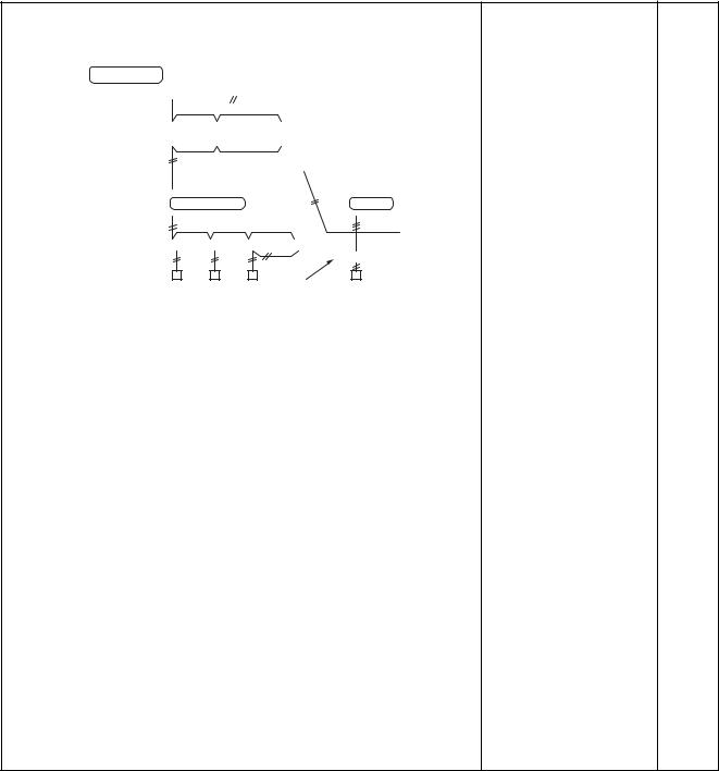
1-9-2 LONWORKS
|
|
|
|
|
|
|
System diagram |
Model |
Reference |
||||||||||||||||||||||
|
|
|
|
|
|
|
N o . |
||||||||||||||||||||||||
|
|
|
|
|
|
|
|
|
|
|
|
|
|
|
|
|
|
|
|
|
|
|
|
|
|
|
|
|
|
|
|
|
|
|
|
|
|
|
|
|
|
|
|
|
|
|
|
|
|
|
|
|
|
|
|
|
|
|
|
|
|
|
|
LON Center |
|
|
|
|
|
|
|
|
|
|
|
|
|
|
|
|
|
|
|
|
|
|
|
|
|
|
|
• LON Gateway |
|
||
|
|
|
|
|
LON Talk |
|
|
|
|
|
|
|
|
|
|
|
|
|
TCB-IFLN**** |
|
|||||||||||
|
|
|
|
|
|
|
|
|
|
|
|
|
|
|
|
|
|
|
|
|
|
|
|
|
|
|
|
|
• “1 : 1 model” connection |
||
LON |
|
|
|
|
|
|
|
|
|
|
|
|
|
|
|
|
|
|
|
|
|
|
|
|
interface |
|
|||||
TCB- |
|
TCB- |
• • • |
TCB- |
|
|
|
|
|
|
|
|
|
|
|
||||||||||||||||
Interfaces |
|
|
|
|
|
|
|
IFLN060 |
|
|
|
|
|
|
|
|
|
|
|
|
|
TCB-PCNT30TLE |
|
||||||||
|
|
|
|
|
|
|
|
|
|
|
|
|
|
|
|
|
|
|
|
|
|
|
|
|
|
|
|
|
|
RAV-SM560KRT-E, |
|
|
|
|
|
|
|
|
|
|
|
|
|
|
|
|
|
|
|
|
|
|
|
|
|
|
|
|
|
|
|
|
|
|
|
|
|
|
|
|
|
|
|
|
|
|
|
|
|
|
|
|
|
|
|
|
|
|
|
|
|
|
|
SM800KRT-E are not |
|
|
|
|
|
|
|
Super MMS |
|
|
|
|
|
|
|
|
|
* 1 |
|
available |
|
||||||||||||
|
|
|
|
|
|
|
|
|
|
|
|
|
|
|
|
|
|||||||||||||||
|
|
|
|
|
|
|
|
|
|
|
|
|
|
|
|
|
|
|
|
|
|
|
|
|
|
|
|
|
<Indoor remote |
|
|
|
|
|
|
|
|
|
|
|
|
|
|
|
|
|
|
|
|
|
|
|
|
|
|
|
|
|
|
|
|
||
|
|
|
|
|
|
|
|
|
|
|
|
|
|
|
|
|
|
|
|
|
|
|
|
|
|
|
|
|
controller> |
|
|
|
|
|
|
|
|
|
|
|
|
|
|
|
|
|
|
|
|
|
|
|
|
|
|
|
|
|
|
|
|
||
|
|
|
|
|
|
|
|
|
|
|
|
|
|
|
|
|
|
|
|
|
|
|
|
|
|
|
|
|
• |
Wired remote controller |
|
|
|
|
|
|
|
|
|
|
|
|
|
|
|
|
|
|
|
|
|
|
|
|
|
|
|
|
|
|
|||
|
|
|
|
|
|
|
|
|
|
|
|
|
|
|
|
|
|
"1:1 model" |
RBC-AMT21E |
|
|||||||||||
|
|
|
|
Remote controller |
|
connection interface |
or |
4-7-2 |
|||||||||||||||||||||||
|
|
|
|
|
|
|
|
|
|
|
|
|
|
|
|
|
|
|
|
|
|
|
|
|
|
|
|
|
• |
|
|
|
|
|
|
|
|
|
|
|
|
|
|
|
|
|
|
|
|
|
|
|
|
|
|
|
|
|
|
|
Simple remote controller |
||
*1 TOSHIBA Digital Inverter System and Super Digital Inverter System |
RBC-AS21E |
|
|||||||||||||||||||||||||||||
The LONWORKS interface shall be connected between a building |
|
|
|||||||||||||||||||||||||||||
management computer and the Super HRM and Super MMS system. |
|
|
|||||||||||||||||||||||||||||
[LONWORKS Gateway]
■Command
•Operation : ON/OFF
• Mode |
: Cool/Heat/Fan |
•Temperature setting
•Center/Local
■Monitor
•Operation : ON/OFF
• Mode |
: Cool/Heat/Fan/failure |
•Temperature setting
•Room temperature
•Center/Local
22
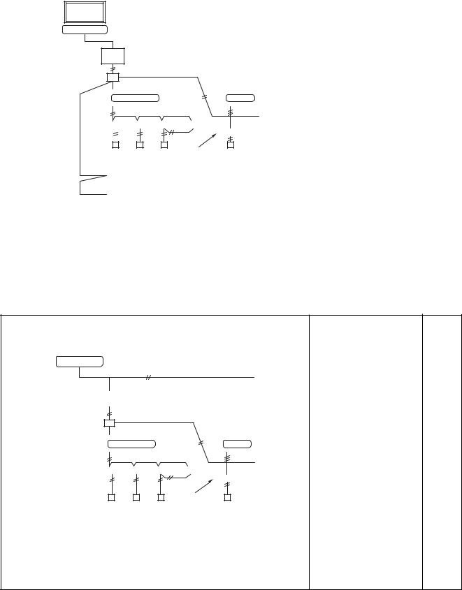
1-9-3 Windows based central controller
|
|
|
|
|
|
|
|
|
System diagram |
|
Model |
|
Reference |
||||||||||||||||||||||||||||||||||||
|
|
|
|
|
|
|
|
|
|
|
N o . |
||||||||||||||||||||||||||||||||||||||
|
|
|
|
|
|
|
|
|
|
|
|
|
|
|
|
|
|
|
|
|
|
|
|
|
|
|
|
|
|
|
|
|
|
|
|
|
|
|
|
|
|
|
|
|
|
|
|
|
|
|
|
|
|
|
|
|
|
|
|
|
|
|
|
|
|
|
|
|
|
|
|
|
|
|
|
|
|
|
|
|
|
|
|
|
|
|
|
|
|
|
|
|
|
|
|
|
|
|
|
|
|
|
|
|
|
|
|
|
|
|
|
|
|
|
|
|
|
|
|
|
|
|
|
|
|
|
|
|
|
|
|
|
|
|
|
|
|
|
|
|
|
|
|
|
|
• WINDOWS based |
|
|
|
|
|
|
|
|
|
|
|
|
|
|
|
|
|
|
|
|
|
|
|
|
|
|
|
|
|
|
|
|
|
|
|
|
|
|
|
|
|
|
|
|
|
|
|
|
|
|
central controller |
|
|
|
|
|
|
Personal computer on site |
|
BMS-LSV** |
|
|
|||||||||||||||||||||||||||||||||||||||||
|
|
|
|
|
|
|
|
|
|
|
|
|
|
|
|
|
|
|
|
|
|
|
|
|
|
|
|
|
|
|
|
|
|
|
|
|
|
|
|
|
|
|
|
|
|
• TCS-Net Relay Interface |
|
||
|
|
|
|
|
|
|
|
|
|
|
|
|
|
|
|
|
|
|
|
|
|
|
|
|
|
|
|
|
|
|
|
|
|
|
|
|
|
|
|
|
|
|
|
|
|
|
BMS-IFLSV1E |
|
|
|
|
|
|
|
|
|
|
|
|
|
|
|
|
|
|
|
|
|
|
|
|
|
|
|
|
|
|
|
|
|
|
|
|
|
|
|
|
|
|
|
|
|
|
|
|
• Intelligent server |
|
|
|
Local server |
|
|
|
|
|
|
|
|
|
|
|
|
|
|
|
|
|
|
|
|
|
|
|
BMS-LSV2E |
|
|
|||||||||||||||||||||||
|
|
|
|
|
|
|
|
|
|
|
|
|
|
|
|
|
|
|
|
|
|
|
BMS-STC01E |
|
|
||||||||||||||||||||||||
|
|
|
|
|
|
|
|
|
|
|
|
|
|
|
|
|
|
|
|
|
|
|
|
|
|
|
|
|
|
|
|
|
|
|
|
|
|
|
|
|
|
|
|
|
|
|
|
|
|
Relay Interface |
|
|
|
|
|
|
|
|
|
|
|
|
|
|
|
|
|
|
|
|
|
|
|
|
|
|
|
|
|
|
|
|
|
|
|
|
|
|
|
|
|
|
|
• |
Energy Monitoring |
|
|
||
|
|
|
|
|
|
|
|
|
|
|
|
|
|
|
|
|
|
|
|
|
|
|
|
|
|
|
|
|
|
|
|
|
|
|
|
|
|
|
|
|
|
|
|
|
|||||
|
|
|
|
|
|
|
|
|
|
|
|
|
|
|
|
|
|
|
|
|
|
|
|
|
Relay Interface |
|
|
||||||||||||||||||||||
|
|
|
|
|
|
|
|
|
|
|
|
|
|
|
|
|
|
|
|
|
|
|
|
|
|
|
|
|
|
|
|
|
|
|
|
|
|
|
|
|
|
|
|
|
|
|
|
|
|
|
|
|
|
|
|
|
|
Super MMS |
|
|
|
|
|
|
|
|
|
|
|
|
|
|
|
|
|
|
|
* 1 |
|
BMS-IFWH3E |
|
|
|||||||||||||||||
|
|
|
|
|
|
|
|
|
|
|
|
|
|
|
|
|
|
|
|
|
|
|
|
|
|
|
|
|
|
||||||||||||||||||||
|
|
|
|
|
|
|
|
|
|
|
|
|
• |
Digital I/O Relay |
|
4-7-3 |
|||||||||||||||||||||||||||||||||
|
|
|
|
|
|
|
|
|
|
|
|
|
|
|
|
|
|
|
|
|
|
|
|
|
|
|
|
|
|
|
|
|
|
|
|
|
|
|
|
|
|
|
|
|
|
|
Interface |
|
|
|
|
|
|
|
|
|
|
|
|
|
|
|
|
|
|
|
|
|
|
|
|
|
|
|
|
|
|
|
|
|
|
|
|
|
|
|
|
|
|
|
|
|
|
|
|
|
BMS-IFDD01E |
|
|
|
|
|
|
|
|
|
|
|
|
|
|
|
|
|
|
|
|
|
|
|
|
|
|
|
|
|
|
|
|
|
|
|
|
|
|
|
|
|
|
|
|
|
|
|
|
• |
“1 : 1 model” connection |
|
|
|
|
|
|
|
|
|
|
|
|
|
|
|
|
|
|
|
|
|
|
|
|
|
|
|
|
|
|
|
|
|
|
|
|
|
|
|
|
|
|
|
|
|
|
|
|
|
|||
|
|
|
|
|
|
|
|
|
|
|
|
|
|
|
|
|
|
|
|
|
|
|
|
|
|
|
|
|
|
|
|
|
|
|
|
|
|
|
|
|
|
|
|
|
|
|
interface |
|
|
|
|
|
|
|
|
|
|
|
|
|
|
|
|
|
|
|
|
|
|
|
|
|
|
|
|
|
|
|
|
|
|
|
|
|
|
|
|
|
|
|
|
|
|
|
|
|
|
|
|
|
|
|
|
|
|
|
|
|
|
|
|
|
|
|
|
|
|
|
|
|
|
|
|
|
|
|
|
|
|
|
"1:1 model" |
|
TCB-PCNT30TLE |
|
|
||||||||||||||
|
|
|
|
Remote controller |
|
|
|
|
|
|
|
connection interface |
RAV-SM560KRT-E, |
|
|||||||||||||||||||||||||||||||||||
|
|
|
|
|
|
|
|
|
|
|
|
|
|
|
|
|
|
|
|
|
|
|
|
|
|
|
|
|
|
|
|
|
|
|
|
|
|
|
|
|
|
|
|
|
|
|
|
|
|
|
|
|
|
|
|
|
|
|
|
|
|
|
Energy monitoring relay interface |
|
SM800KRT-E are not |
|
|||||||||||||||||||||||||||||||||
|
|
|
|
|
|
|
|
|
|
|
|
|
Digital I/O relay interface |
|
available |
|
|
||||||||||||||||||||||||||||||||
|
|
|
|
|
|
|
|
|
|
|
|
|
|
||||||||||||||||||||||||||||||||||||
|
|
|
|
|
|
|
|
|
|
|
|
|
|
|
|
|
|||||||||||||||||||||||||||||||||
|
|
|
|
|
|
|
|
|
|
|
|
|
|
|
|
|
|
|
|
|
|
|
|
|
|
|
|
|
|
|
|
|
|
|
|
|
|
|
|
|
|
|
|
|
|
<Indoor remote |
|
|
|
|
|
|
|
|
|
|
|
|
|
|
|
|
|
|
|
|
|
|
|
|
|
|
|
|
|
|
|
|
|
|
|
|
|
|
|
|
|
|
|
|
|
|
|
|
|
|
|
||
|
|
|
|
|
|
|
|
|
|
|
|
|
|
|
|
|
|
|
|
|
|
|
|
|
|
|
|
|
|
|
|
|
|
|
|
|
|
|
|
|
|
|
|
|
|
controller> |
|
|
|
*1 TOSHIBA Digital Inverter System and Super Digital Inverter System |
• |
Wired remote controller |
|
||||||||||||||||||||||||||||||||||||||||||||||
The local server shall be “Plug-in” into a customer’s personal computer. |
|
RBC-AMT21E |
|
|
|||||||||||||||||||||||||||||||||||||||||||||
• |
Simple remote controller |
|
|||||||||||||||||||||||||||||||||||||||||||||||
|
|
|
|
|
|
|
|
|
|
|
|
|
|
|
|
|
|
|
|
|
|
|
|
|
|
|
|
|
|
|
|
|
|
|
|
|
|
|
|
|
|
|
|
|
|
|
|||
|
|
|
|
|
|
|
|
|
|
|
|
|
|
|
|
|
|
|
|
|
|
|
|
|
|
|
|
|
|
|
|
|
|
|
|
|
|
|
|
|
|
|
|
|
|
|
RBC-AS21E |
|
|
|
|
|
|
|
|
|
|
|
|
|
|
|
|
|
|
|
|
|
|
|
|
|
|
|
|
|
|
|
|
|
|
|
|
|
|
|
|
|
|
|
|
|
|
|
|
|
|
|
|
1-9-4 BACnet
|
|
|
|
|
|
|
|
|
|
|
|
System diagram |
|
Model |
|
Reference |
||||||||||||||||||||||||||||||||||
|
|
|
|
|
|
|
|
|
|
|
|
|
|
N o . |
||||||||||||||||||||||||||||||||||||
|
|
|
|
|
|
|
|
|
|
|
|
|
|
|
|
|
|
|
|
|
|
|
|
|
|
|
|
|
|
|
|
|
|
|
|
|
|
|
|
|
|
|
|
|
|
|
|
|
|
|
|
|
|
|
|
|
|
|
|
|
|
|
|
|
|
|
|
|
|
|
|
|
|
|
|
|
|
|
|
|
|
|
|
|
|
|
|
|
|
|
|
|
|
|
|
|
|
|
|
|
|
BAC net center |
|
|
|
|
|
|
|
|
|
|
|
|
|
|
|
|
|
|
|
|
|
|
• BACnet local server |
|
|
|||||||||||||||||||||||||
|
|
|
|
|
|
|
|
|
|
|
|
|
|
|
|
|
|
|
|
|
|
|
|
|
|
|
|
|
|
|
|
|
|
|
|
|
|
|
|
|
|
|
|
|
|
|
|
BMS-LSV****** |
|
|
Local server |
|
|
|
|
|
|
|
|
|
|
|
|
|
|
|
|
|
|
|
|
|
|
|
|
|
|
||||||||||||||||||||||||
|
TCB- |
|
|
|
|
|
|
|
|
|
|
|
|
|
|
|
|
|
|
|
|
|
|
|
|
|
|
|
|
|
|
|
|
|
|
|
• TCS-Net Relay Interface |
|
||||||||||||
|
|
|
|
|
|
|
|
|
|
|
|
|
|
|
|
|
|
|
|
|
|
|
|
|
|
|
|
|
|
|
|
|
|
|
|
|
|
|
|
|
|
|
|
|
|
|
|
BMS-IFLSV1E |
|
|
|
|
|
|
|
|
|
|
|
|
|
|
|
|
|
|
|
|
|
|
|
|
|
|
|
|
|
|
|
|
|
|
|
|
|
|
|
|
|
|
|
|
|
|
|
|
|
|
|
|
|
TCS-Net |
|
|
|
|
|
|
|
|
|
|
|
|
|
|
|
|
|
|
|
|
|
|
|
|
• |
“1 : 1 model” connection |
|
|||||||||||||||||||||||
|
|
|
|
|
|
|
|
|
|
|
|
|
|
|
|
|
|
|
|
|
|
|
|
|||||||||||||||||||||||||||
Relay Interface |
|
|
|
|
|
|
|
|
|
|
|
|
|
|
|
|
|
|
|
|
|
|
|
|
|
interface |
|
|
||||||||||||||||||||||
|
|
|
|
|
|
|
|
|
|
|
|
|
|
|
|
|
|
|
|
|
|
|
|
|
|
|||||||||||||||||||||||||
|
|
|
|
|
|
|
|
|
Super MMS |
|
|
|
|
|
|
|
|
|
|
|
|
|
|
|
|
|
|
|
* 1 |
|
TCB-PCNT30TLE |
|
|
|||||||||||||||||
|
|
|
|
|
|
|
|
|
|
|
|
|
|
|
|
|
|
|
|
|
|
|
|
|
RAV-SM560KRT-E, |
|
||||||||||||||||||||||||
|
|
|
|
|
|
|
|
|
|
|
|
|
|
|
|
|
|
|
|
|
|
|
|
|
|
|
|
|
|
|
|
|
|
|
|
|
|
|
|
|
|
|
|
|
|
|
|
|
|
4-7-4 |
|
|
|
|
|
|
|
|
|
|
|
|
|
|
|
|
|
|
|
|
|
|
|
|
|
|
|
|
|
|
|
|
|
|
|
|
|
|
|
|
|
|
|
|
|
|
|
|
|||
|
|
|
|
|
|
|
|
|
|
|
|
|
|
|
|
|
|
|
|
|
|
|
|
|
|
|
|
|
|
|
|
|
|
|
|
|
|
|
|
|
|
|
|
|
|
|
|
SM800KRT-E are not |
|
|
|
|
|
|
|
|
|
|
|
|
|
|
|
|
|
|
|
|
|
|
|
|
|
|
|
|
|
|
|
|
|
|
|
|
|
|
|
|
|
|
|
|
|
|
|
|
|
|
available |
|
|
|
|
|
|
|
|
|
|
|
|
|
|
|
|
|
|
|
|
|
|
|
|
|
|
|
|
|
|
|
|
|
|
|
|
|
|
|
|
|
|
|
|
|
|
|
|
|
<Indoor remote |
|
|
|
|
|
|
|
|
|
|
|
|
|
|
|
|
|
|
|
|
|
|
|
|
|
|
|
|
|
|
|
|
|
|
|
|
|
|
|
|
|
|
|
|
|
|
|
|
|
|
|
|
||
|
|
|
|
|
|
|
|
|
|
|
|
|
|
|
|
|
|
|
|
|
|
|
|
|
|
|
|
|
|
|
|
"1:1 model" |
controller> |
|
|
|||||||||||||||
|
|
|
|
|
|
Remote controller |
|
|
|
|
|
|
|
connection interface |
• |
Wired remote controller |
|
|||||||||||||||||||||||||||||||||
|
|
|
|
|
|
|
|
|
|
|
|
|
|
|
|
|
|
|
|
|
|
|
|
|
|
|
|
|
||||||||||||||||||||||
|
|
|
|
|
|
|
|
|
|
|
|
|
|
|
|
|
|
|
|
|
|
|
|
|
|
|
|
|
|
|
|
|
|
|
|
|
|
|
|
|
|
|
|
|
|
|
|
|||
|
|
|
|
|
|
|
|
|
|
|
|
|
|
|
|
|
|
|
|
|
|
|
|
|
|
|
|
|
|
|
|
|
|
|
|
|
|
|
|
|
|
|
|
|
|
|
|
RBC-AMT21E |
|
|
*1 TOSHIBA Digital Inverter System and Super Digital Inverter System
• Simple remote controller The local server shall be connected under the BACnet network, and shall RBC-AS21E
be connected the Super HRM and Super MMS system through the interface.
(Note) For “1-9-1” to “1-9-4”, details of specification were not available at the time of publication. For further information (set up, adjustment), consult the sales subsidiary.
23

2
SYSTEM WIRING DIAGRAM
AND
CONTROL WIRING METHOD
2-1 Applicable model and connectable units
2-2 System wiring diagram
2-2-1 For VRF system only
2-2-2 For combined system with “1:1model” 2-3 Design of control wiring
2-4 Earth method of shield wiring
2-4-1 For VRF system only
2-4-2 For combined system with “1:1model” 2-5 General requirement for control wiring
24
2-1 Applicable model and connectable units
1)Applicable model
• VRF system ............... Super modular multi system (Super MMS)
Super heat recovery multi system (Super HRM)
• 1:1 model .................. Super digital inverter, Digital inverter
2)The number of connectable units
[1] For only VRF system
|
Connected unit |
No. of units |
Note |
|
|
|
|
1 |
Outdoor unit |
Up to 16 units |
|
|
(Header unit) |
|
|
|
|
|
|
2 |
Outdoor unit |
Up to 3 units |
In the same refrigerant system |
|
(Follower unit) |
|
|
|
|
|
|
3 |
Indoor unit |
Up to 64 units |
• Max 64 units in case of group control* |
|
|
|
• Max. 48 units for one refrigerant system |
4 |
Group control for |
Up to 8 units |
|
|
indoor units |
|
|
|
|
|
|
5 |
Central control |
Up to 10 units |
• Central remote controller |
|
device |
|
|
|
|
|
|
* Follower indoor unit in a group control must be counted as one indoor unit.
[2] For combined system with Digital Inverter / Super Digital Inverter
|
Connected unit |
No. of units |
Note |
|
|
|
|
1 |
Outdoor unit |
Up to 16 units |
|
|
(Header unit for |
|
|
|
VRF system) |
|
|
|
|
|
|
2 |
Outdoor unit |
Up to 3 units |
In the same refrigerant system |
|
(Follower unit for |
|
|
|
VRF system) |
|
|
|
|
|
|
3 |
Indoor unit |
Up to 64 units |
• Max. 64 units for total number of indoor units for both system. |
|
|
|
* For 1:1 model, follower indoor units of twin control and group |
|
|
|
control must not be counted. |
|
|
|
* For VRF system, Max. 48 indoor units in one refrigerant |
|
|
|
system. |
4 |
Group control for |
Up to 8 units |
|
|
indoor units |
|
|
|
|
|
|
5 |
Central control |
Up to 10 units |
• Central remote controller |
|
device |
|
|
|
|
|
|
*Max. 64 refrigerant system can be controlled for total number of VRF system and 1:1 model.
(However, for VRF system, up to 16 refrigerant system can be connectable.)
*“1:1 model” connection interface is connected to the indoor unit of 1:1 model.
25
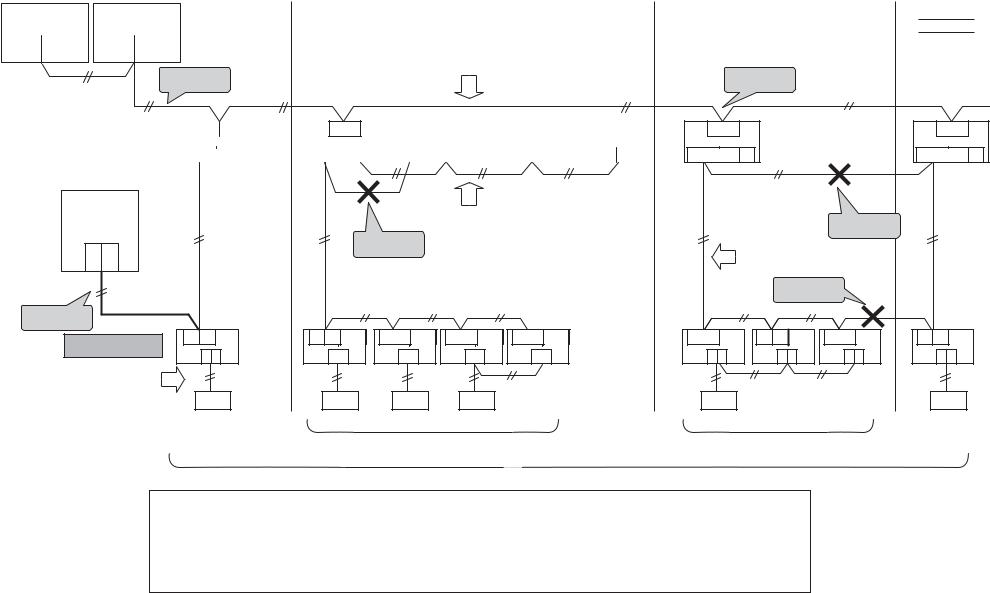
2-2 System wiring diagram
2-2-1 For VRF system only
Central Control |
Central Control |
Refrigerant |
|
|
Refrigerant |
|
Refrigerant |
||||||
Device |
Device |
System 1 |
|
|
System 2 |
|
|
System 3 |
|
||||
|
|
|
|
|
|
|
|
|
|
|
|
|
|
|
U1 U2 |
|
|
U1 U2 |
|
|
|
Central control wiring |
|
|
|
||
|
U3 U4 |
|
|
U3 U4 |
|
|
|
|
|
|
|||
|
|
|
|
|
|
(Max.16 units can be connectable) |
|
|
|
||||
|
|
|
|
|
Note [4] |
|
|
Note [3] |
|||||
|
|
|
|
|
Header |
Follower |
Follower |
Follower |
|||||
|
|
|
|
|
|
|
|
|
|||||
Max. 10 central |
|
|
|
|
Unit |
Unit |
Unit |
Unit |
|
|
|||
control devices |
|
|
|
|
|
|
|
|
|
|
|
||
26
|
|
|
|
U3U4 |
|
|
|
|
U3U4 |
|
|
U3U4 |
|
|
|
|
U3U4 |
|
|
|
|
U3U4 |
|
|
|||||||||||
Outdoor Unit |
|
|
|
|
|
|
|
|
|
|
|
|
|
|
|
|
|
|
|
|
|
|
|
|
|
|
|
|
|
|
|
|
|
|
|
|
|
|
|
|
|
|
|
|
|
|
|
|
|
|
|
|
|
|
|
|
|
|
|
|
|
|
|
|
|
|
|
|
|
|
|
|
|
|
U1U2 |
|
U5U6 |
|
|
|
U1U2 |
|
U5U6 |
|
|
U1U2 |
|
U5U6 |
|
|
U1U2 |
|
U5U6 |
|
|
U1U2 |
|
U5U6 |
|
||||||||
|
|
||||||||||||||||||||||||||||||||||
Header
Unit
Central
Control
Device
U1 U2
U3 U4
Control wiring between outdoor units (Max. 4 units can be connected.)
Note [1]
Note [5] |
|
|
|
|
U1U2 |
U1U2 |
U1U2 |
U1U2 |
U1U2 |
Indoor Unit |
|
|
|
|
A B |
A B |
A B |
A B |
A B |
U3U4 Header
Unit
U1U2
 U5U6
U5U6
Note [2]
Control wiring Between indoor and outdoor units
Note [2]
U1U2 U1U2 U1U2
A B A B A B
Remote controller Wiring
Remote |
Remote controller |
Remote controller |
Controller |
Max. 48 indoor units can be connected |
Group control operation |
|
||
|
in one refrigerant system |
(Max. 8 units) |
|
Max. 64 indoor units for all refrigerant circuits |
|
Note) [1] Don’t connect control wiring between indoor and outdoor units to several outdoor units.
(Outdoor unit to which control wiring between indoor and outdoor unit is connected becomes the header outdoor unit automatically.)
[2]Don’t connect control wiring between indoor and outdoor units to other refrigerant system.
[3]Connect central control wiring to the header outdoor unit.
[4]Connect central control devices to central control wiring.
[5]Central control devices can be also connected to control wiring between indoor and outdoor units.
Refrigerant
System 4
U3U4
U1U2
 U5U6
U5U6
Header
Unit
U1U2
A B
Remote
Controller
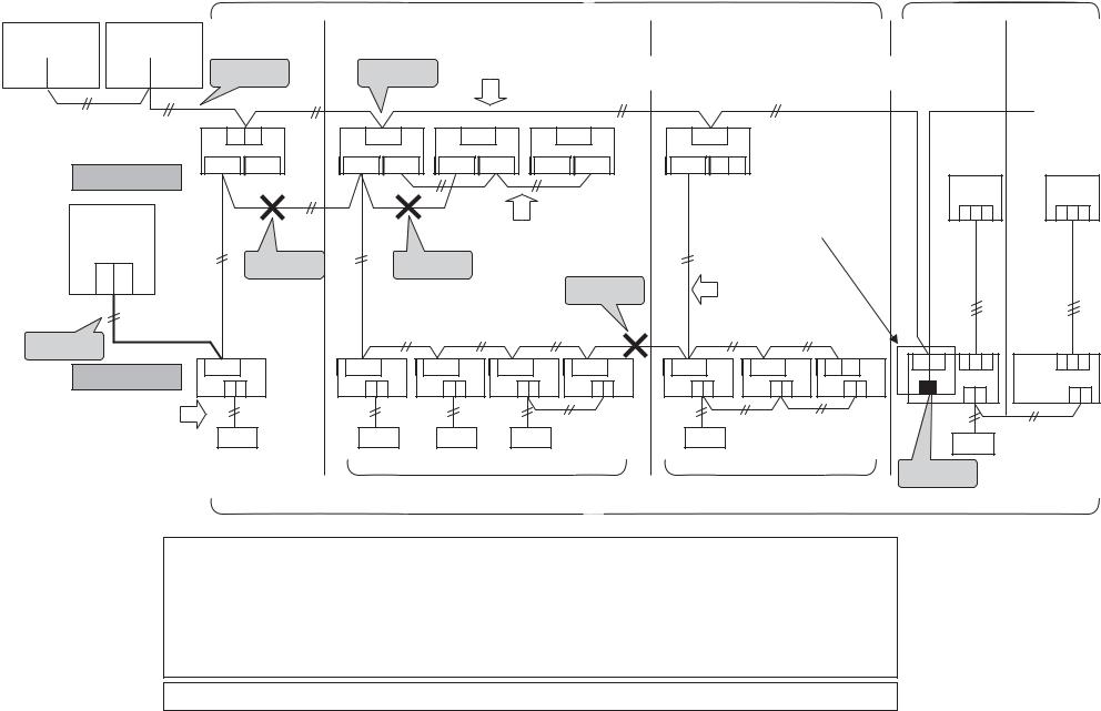
2-2-2 For combined system with “1:1 model”
Central Control |
Central Control |
Refrigerant |
|
|
||||
System 1 |
|
|||||||
Device |
Device |
|
||||||
|
|
|
||||||
|
U1 U2 |
|
|
U1 U2 |
|
Note [6] |
Note [3] |
|
|
U3 U4 |
|
|
U3 U4 |
|
|||
|
|
|
|
|
|
|
||
|
|
|
“1:1 model” (Super digital Inverter, |
||||
VRF system |
|
|
Digital Inverter) |
||||
Refrigerant |
|
Refrigerant |
Refrigerant |
Refrigerant |
|||
|
|
|
|
|
|
|
|
System 2 |
|
System 3 |
System 4 |
System 5 |
|||
|
|
|
|
|
|
|
|
Central control wiring : Max 64 refrigerant system for both VRF system and 1:1 model.
Max 16 refrigerant system for VRF system.
27
Max. 10 Central |
|
control devices |
Header |
|
Unit |
Outdoor Unit
Central
Control
Device
U1 U2
U3 U4
Note [7]
Indoor Unit
Remote controller Wiring
|
|
Follower |
unit |
Follower unit |
|
Header |
|
|
|
|
U3U4 |
U3U4 |
U3U4 |
|
U3U4 |
U3U4 |
|
|
|
||
|
|
|
|
|
|
|
unit |
|
|
|
U1U2 U5U6 |
U1U2 U5U6 |
U1U2 U5U6 |
U1U2 U5U6 |
U1U2 U5U6 |
|
|
|
|||
|
|
|
|
|
|
|
“1:1 model” connection |
|
|
|
|
|
Control wiring between outdoor units |
|
interface (TCB-PCNT30TLE) |
|
1 2 3 |
||||
|
|
|
|
|
|
|
||||
|
|
(Max. 4 units can be connected.) |
|
|
|
|
|
|||
Note [2] |
Note [1] |
|
|
|
Control wiring |
|
|
|
||
|
|
|
|
|
|
|
|
|
||
|
|
|
|
|
Note [2] |
between indoor |
|
|
|
|
|
|
|
|
|
and outdoor units |
|
|
|
||
|
|
|
|
|
|
|
|
|
||
|
|
|
|
|
|
|
|
|
Header |
|
|
|
|
|
|
|
|
|
|
unit |
|
U1U2 |
U1U2 |
U1U2 |
U1U2 |
U1U2 |
U1U2 |
U1U2 |
U1U2 |
U3U4 |
1 2 3 |
|
|
|
|||||||||
A B |
A B |
A B |
|
A B |
A B |
A B |
A B |
A B |
|
A B |
|
|
|
|
|
|
|
|
|
|
|
1 2 3
Follower unit
1 2 3
A B
|
|
|
Remote |
|
Remote |
Remote controller |
Remote controller |
controller |
|
Note [4] [5] |
||||
Controller |
Max 48 indoor units can be connected. |
Group control operation |
||
|
|
|||
|
|
(Max. 8 units) |
|
Max. 64 indoor units for all refrigerant systems (Don,t count follower indoor units of group control and twin control of 1:1 model.)
Note) [1] Don’t connect control wiring between indoor and outdoor units to several outdoor units.
(Outdoor unit to which control wiring between indoor and outdoor units is connected becomes the header outdoor unit automatically.)
[2]Don’t connect control wiring between indoor and outdoor units to other refrigerant system.
[3]Connect central control wiring to the header outdoor unit.
[4]When “1:1 model” is controlled by central control devices, “1:1 model” connection interface is necessary.
[5]In case of twin control on 1:1 model, connect “1:1 model” connection interface to the header indoor unit.
[6]Connect central control devices to central control wiring.
[7]Central control devices can be also connected to control wiring between indoor and outdoor units.
* In case of 1:1 model, address re-setup is needed from wired remote controller. (For details, refer to “3-2-10”).

2-3 Design of control wiring
1.All control wiring is 2-core and non-polarity wire.
2.Be sure to use shield wire for the following wiring to prevent noise trouble.
• Outdoor-outdoor / indoor-indoor / outdoor-indoor control wiring, Central control wiring.
Control wiring between indoor and outdoor units (L1,L2,L3), |
|
|
|
||
Central control wiring (L4) |
|
|
Control wiring between outdoor units (L5) |
||
Wiring |
2-core, non-polarity |
|
|
Wiring |
2-core, non-polarity |
|
|
|
|
|
|
Type |
Shield wire |
|
|
Type |
Shield wire |
|
|
|
|
|
|
Size |
1.25mm2 : Up to 1000m |
|
|
Size |
1.25mm2~ 2.0mm2 |
Length |
2.0mm2 : Up to 2000m |
(*1) |
|
Length |
Up to 100m (L5) |
Central Control |
Note (1) : Total of control wiring length for all refrigerant systems |
“1:1 model” |
||
Device |
( L1 + L2 + L3 + L4 ) |
|||
|
|
|
|
(Super digital Inverter, |
|
U1 U2 |
|
VRF system |
|
|
|
Digital Inverter) |
||
|
U3 U4 |
|
||
|
|
|
|
|
|
|
|
|
|
L4 |
|
|
|
|
|
|
|
|
|
|
Header |
Header |
Follower |
|
Follower |
Follower |
|
Header |
Follower |
|
||
|
|
unit |
unit |
|
unit |
|
unit |
unit |
|
|
|||
|
|
|
|
|
unit |
unit |
|
|
|||||
|
|
U3U4 |
U3U4 |
U3U4 |
|
U3U4 |
U3U4 |
|
|
|
|||
|
Outdoor unit |
|
U3U4 |
U3U4 |
|
|
|||||||
|
|
|
|
|
|
|
|
|
|
||||
28 |
U1U2 U5U6 |
U1U2 U5U6 |
U1U2 U5U6 |
U1U2 U5U6 |
U1U2 U5U6 |
|
|
|
|
1 2 3 |
|||
|
U1U2 U5U6 |
U1U2 U5U6 |
|||||||||||
|
|
L1 |
|
|
|
L5 |
|
|
|
|
|
|
|
|
|
|
|
L2 |
|
|
|
|
L3 |
|
|
|
|
|
Indoor unit |
U1U2 |
U1U2 |
U1U2 |
U1U2 |
U1U2 |
|
U1U2 |
U1U2 |
U3U4 |
1 2 3 |
||
|
A B |
A B |
A B |
|
A B |
A B |
|
U1U2 |
|
||||
|
|
|
|
A B |
|
AB |
AB |
A B |
|||||
|
|
|
|
|
|
|
|
|
|
||||
|
|
|
|
|
|
|
|
|
L7 |
|
L6 |
|
|
|
|
|
|
|
|
|
|
|
|
|
|
|
|
|
Remote controller |
Remote controller |
Remote controller wiring (L6,L7) |
|
|
|
|
|
Wire |
2-core, non-polarity |
|
Size |
0.5mm2~ 2.0mm2 |
|
Length |
Up to 500m ( L6 + L7 ) |
|
|
Up 400m when wireless remote controller exists in a group control. |
|
|
Up to 200m total length of control wiring between indoor units ( L6 ) |
|
|
|
|
Remote controller
Remote controller
1:1 model connection interface (TCB-PCNT30TLE)
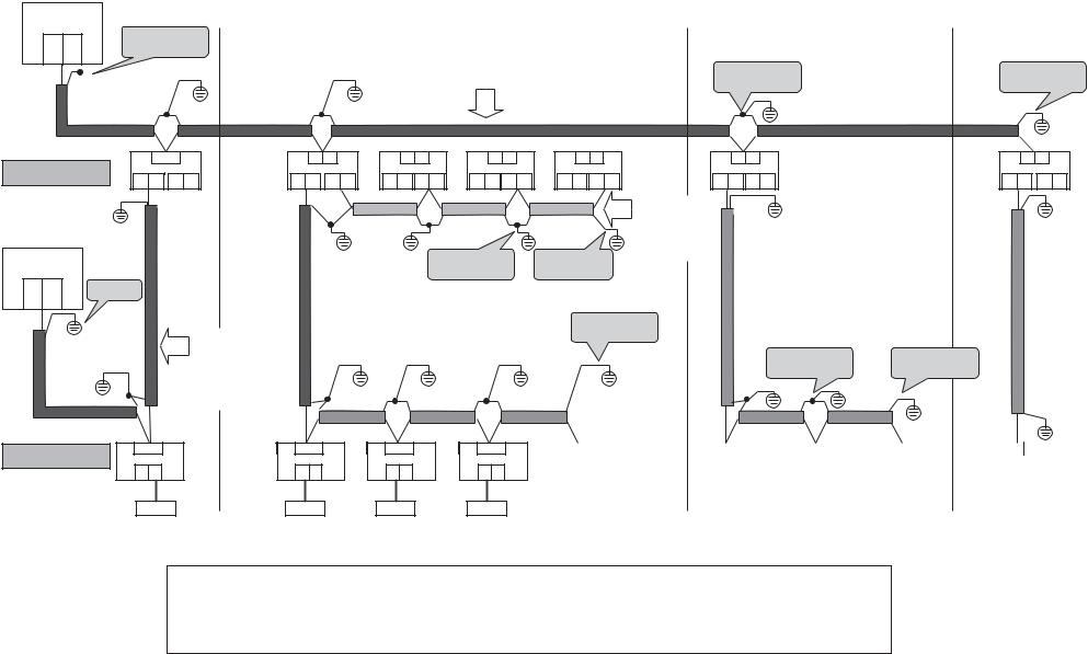
2-4 Earth method of shield wiring
2-4-1 For VRF system only
Central control device
|
U1 U2 |
|
Note [2] |
|
|
|
|
|
U2 U4 |
|
|
|
|
|
|
|
(Open) |
|
|
|
Central control wiring |
||
|
|
|
|
|
|
||
|
|
|
|
|
|
Follower unit |
Follower unit |
|
Outdoor unit |
U3U4 |
Header |
U3U4 |
U3U4 |
U3U4 |
|
|
U1U2 U5U6 |
unit |
U1U2 U5U6 |
U1U2 U5U6 |
U1U2 U5U6 |
||
|
|
|
|
||||
|
|
|
Header |
|
|
|
|
|
|
|
unit |
|
|
|
|
|
Central control |
|
|
|
|
|
Note [1] |
|
device |
|
|
|
|
|
|
29 |
|
|
|
|
|
|
|
U1 U2 |
Note [1] |
|
|
|
|
||
|
U3 U4 |
|
|
|
|
|
|
|
|
|
Control wiring |
|
|
|
|
|
|
|
between |
|
|
|
|
|
|
|
indoor and |
|
|
|
|
|
|
|
outdoor units |
|
|
|
|
|
Indoor unit |
U1U2 |
|
U1U2 |
U1U2 |
U1U2 |
|
|
|
|
|
|
|
||
|
|
|
A B |
|
A B |
A B |
A B |
|
|
|
Remote controller |
|
Remote controller |
|
|
Note [1] |
Note [2] |
Follower unit
U3U4 |
U3U4 |
U3U4 |
U1U2 U5U6 |
U1U2 U5U6 |
U1U2 U5U6 |
Control wiring between outdoor units
Note [1]
Note [2]
Note [1] |
Note [1] |
|
|
U1U2 |
|
|
|
|
U1U2 |
|
|
|
|
U1U2 |
|
|
|
|
U1U2 |
|
|
|
|
U1U2 |
|
|
||||||||||
|
|
|
|
|
|
|
|
|
|
|
|
|
|
|
|
|
|
|
|
|
|
|
|
|
|
|
|
|
|
|
|
|
|
|
|
|
A |
B |
|
|
|
|
A |
B |
|
|
|
|
A |
B |
|
|
|
|
A |
B |
|
|
|
|
A |
B |
|
|
|||||
|
|
|
|
|
|
|
|
|
|
|
|
|
|
|
|
|
|
|
|
|
|
|
|
|
|
|
|
|
|
|
|
|
|
|
|
|
|
|
|
|
|
|
|
|
|
|
|
|
|
|
|
|
|
|
|
|
|
|
|
|
|
|
|
|
|
|
|
|
|
|
|
|
|
|
|
|
|
|
Remote controller |
|
|
|
|
|
Remote controller |
|||||||||||||||||||
Note) [1] Be sure to close (connect) the end of shield wires, and perform the functional grounding for the end of wires which are connected to both indoor and outdoor units.
[2]For the shield wires which are connected between the central remote controller and the outdoor units, perform the functional grounding at only one end of central control wiring. (Leave the other end of the wire at its final termination as an open wire.)
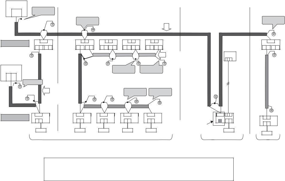
2-4-2 For combined system with “1:1 model”
30
Central Control |
|
|
|
|
|
|
|
|
Device |
|
|
|
|
|
|
|
|
U1 U2 |
Note [2] |
|
|
|
|
|
|
|
U3 U4 |
|
|
|
|
|
|
|
|
(Open) |
|
|
Note [1] |
|
|
Central control wiring |
|
Note [2] |
|
|
|
|
|
|
|
||
|
|
|
|
|
|
|
|
|
|
|
|
|
Follower unit |
Follower unit |
Follower unit |
|
|
Outdoor unit |
U3U4 |
Header |
U3U4 |
U3U4 |
U3U4 |
U3U4 |
Header |
U3U4 |
|
unit |
|
|
|
|
unit |
|
|
|
U1U2 U5U6 |
U1U2 U5U6 |
U1U2 U5U6 |
U1U2 U5U6 |
U1U2 U5U6 |
U1U2 U5U6 |
||
|
|
|
Header
|
unit |
|
|
|
Control wiring |
|
|
|
|
|
|
between |
1 2 3 |
|
|
|
|
|
outdoor units |
|
Central Control |
|
|
Note [1] |
Note [1] |
|
|
Device |
|
|
|
|
||
|
|
|
|
|
|
|
U1 U2 |
|
|
|
|
|
|
U3 U4 |
|
|
|
|
|
|
Note [1] |
|
|
|
|
|
|
|
Control wiring |
|
|
|
|
|
|
between |
|
Note [1] |
Note [1] |
|
|
|
indoor and |
|
|
|
||
|
|
|
|
|
|
|
|
outdoor units |
|
|
|
|
|
U1U2 |
U1U2 |
U1U2 |
U1U2 |
U1U2 |
|
U3U4 1 2 3 |
Indoor unit |
|
|
|
|
|
U1U2 |
A B |
A B |
A B |
A B |
A B |
1:1 model connection |
A B |
|
|
|
|
|
A B |
|
|
|
|
|
|
interface |
|
|
|
|
|
|
|
|
|
|
|
|
|
(TCB-PCNT30TLE) |
|
Remote controller |
Remote controller |
VRF system |
1:1 model |
VRF |
|
( Super digital inverter, |
system |
|
Digital inverter ) |
|
Note) [1] Be sure to close (connect) the end of shield wires, and perform the functional grounding for the end of wires which are connected to both indoor and outdoor units.
[2]For the shield wires which are connected between the central remote controller and the outdoor units, perform the functional grounding at only one end of central control wiring. (Leave the other end of the wire at its final termination as an open wire.)
 Loading...