


SERVICE MANUAL 2060/2860/70
PLAIN PAPER COPIER
AUTOMATIC DUPLEXING UNIT MD-5002
Click the Page Only button to close the overview area of the window.
Click the Bookmarks and Page button to open the Contents and display bookmarks created for the document. Click a bookmark’s name to go to the Page marked by that bookmark.
Click the Thumbnails and Page button to open the overview area and display thumbnail images of each document page. Click a thumbnail to go to the page marked by that thumbnail.
Copyright TOSHIBA CORPORATION 1995
ALL RIGHTS RESERVED
GENERAL PRECAUTIONS REGARDING THE INSTALLATION AND SERVICE FOR THE COPIER 2060, 2860/70 AND THE AUTOMATIC DUPLEXING UNIT MD-5002
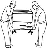
1.Transportation/Installation
•When transporting/installing the copier, use two persons and be sure to use the positions as indicated below.
The copier is fairly heavy and weighs approximately 73 kg (161 lb), therefore pay full attention when handling it. (2870: 84 kg)
4 portions
2.Installation
•Be sure to use a dedicated outlet with AC 115V/15A (220V, 240V/10A) or more for its power source.
•The copier must be grounded for safety. Never ground it to a gas pipe or a water pipe.
•Select a suitable place for installation.
Avoid excessive heat, high humidity, dust, vibration and direct sunlight.
•Also provide proper ventilation as the copier emits a slight amount of ozone.
•To insure adequate working space for the copying operation, keep a minimum clearance of 80 cm (32”) on the left, 80 cm (32”) on the right and 10 cm (4”) in the rear.
3.Service of Machines
•Basically, be sure to turn the main switch off and unplug the power cord during service.
•Be sure not to touch high-temperature sections such as the exposure lamp, the fuser unit, the damp heater and their periphery.
•Be sure not to touch high-voltage sections such as the chargers and the high-voltage transformer.
•Be sure not to touch rotating/operating sections such as gears, belts, pulleys, etc.
•When servicing the machines with the main switch turned on, be sure not to touch live sections such as the lamp terminal, etc.
•Use suitable measuring instruments and tools.
4.Main Service Parts for Safety
•The breaker, door switch, fuse, thermostat, thermofuse, thermistor, etc. are particularly important for safety. Be sure to handle/install them properly.
5.Notice Labels
•Be sure to check the rating plate and the cautionary labels such as “Unplug the power cord during service”, “Hot area” etc. to see if there is any dirt on their surface or if they are properly stuck to the copier during servicing.
6.Disposition of Consumable Parts/Packing Materials
•Regarding the recovery and disposal of the copier, supplies, consumable parts and packing materials, it is recommended to follow the relevant local regulations or rules.
7.When parts are disassembled, reassembly is basically the reverse of disassembly unless otherwise noted in this manual or other related documents. Be careful not to reassemble small parts such as screws, washers, pins, E-rings, toothed washers in the wrong places.
8.Basically, the machine should not be operated with any parts removed or disassembled.
9.Precautions Against Static Electricity
•The PC board must be stored in an anti-electrostatic bag and handled carefully using a wristband, because the ICs on it may become damaged due to static electricity.
1.SPECIFICATIONS • ACCESSORIES • OPTIONS • SUPPLIES
1.1 Specifications
Copy process |
|
|
|
Indirect electrophotographic process (dry) |
||
|
|
|
|
|
|
|
Type |
|
|
|
Desk top (console when the pedestal is used) |
||
|
|
|
|
|
|
|
Exposure Type |
|
|
|
Slit exposure with fixed table |
||
|
|
|
|
|
|
|
Acceptable originals |
Kind |
Sheets, books, and 3-dimensional objects. |
||||
|
|
|
|
|
When the document feeder is used: |
|
|
|
|
|
|
Sheet originals only (60 g/m2~90 g/m2) (16 lb.~24 lb.) |
|
|
|
|
Maximum size |
A3 (Ledger) |
||
|
|
|
|
|
|
|
|
|
|
|
|
|
|
Copy paper |
|
|
|
|
|
|
|
|
|
|
|
||
|
Cassette |
Duplexing |
Manual |
Note |
||
|
|
|
|
|
|
|
Size |
|
A3~A5-R |
A3~A6-R |
Adjustable to |
||
|
|
|
|
|
|
|
|
|
(Ledger~Statement-R) |
Unfixed, Arbitary sizes |
|||
|
|
|
|
|
|
|
Thickness |
|
|
64~80 |
64~130 |
Unit: g/m2 |
|
(Weight) |
|
|
(17~22) |
(17~34) |
(Unit: lb.) |
|
|
|
|
|
|
|
|
Special |
|
_ |
|
_ |
OHP film |
|
paper |
|
|
|
|
etc. |
|
|
|
|
|
|
|
|
Dec. 1996 © TOSHIBA |
1 - 1 |
2060, 2860/70 SPECIFICATIONS |
Copy speed |
|
|
|
|
|
|
|
|
|
|
|
|
|
|
|
|
|
|
|
|
|
|
|
|
|
|
|
||
|
|
|
|
|
Cassette/manual |
|
LCF |
|
|
|
||||
|
|
Paper size |
|
2060 |
|
2860 |
|
2060 |
|
|
2860 |
|
|
|
|
|
|
|
|
|
|
|
|
|
|
|
|
|
|
|
|
A4, B5, A5-R |
|
20 |
|
28 |
|
20 |
|
|
28 |
|
|
|
|
|
LT, ST-R |
|
|
|
|
|
|
|
|
|
|
|
|
|
|
|
|
|
|
|
|
|
|
|
|
|
||
|
|
A4-R, B5-R |
|
20 |
|
26 |
|
— |
|
|
— |
|
|
|
|
|
LT-R |
|
|
|
|
|
|
|
|
|
CPM |
|
|
|
|
|
|
|
|
|
|
|
|
|
|
|
|
|
|
|
B4, FOLIO |
|
20 |
|
22 |
|
— |
|
|
— |
|
||
|
|
|
|
|
|
|
|
|||||||
|
|
LG, Computer |
|
|
|
|
|
|
|
|
|
|
|
|
|
|
|
|
|
|
|
|
|
|
|
|
|
||
|
|
A3 |
|
19 |
|
19 |
|
— |
|
|
— |
|
|
|
|
|
LD |
|
|
|
|
|
|
|
|
|
|
|
|
|
|
|
|
|
|
|
|
|
|
|
|
|
|
|
|
|
Reduction/ |
|
15 |
|
15 |
|
15 |
|
|
15 |
|
|
|
|
|
Enlargement |
|
|
|
|
|
|
|
|
|
|
|
|
|
|
|
|
|
|
|
|
|
||||||
|
|
Manual feeding represents the value when the size is set. |
|
|
||||||||||
|
|
|
|
|
|
|
|
|
|
|
|
|
|
|
System copy speed |
|
|
|
|
|
|
|
|
|
|
|
|
|
|
(BLI format) |
|
|
|
|
|
|
|
|
|
|
|
|
|
|
|
|
|
|
Mode |
CPM |
|
|
|
||||||
|
|
|
|
|
|
|
|
|||||||
|
|
|
|
|
|
|
|
|
|
|
|
|
|
|
|
|
|
Original→Copy |
Number of copies |
2060 |
|
|
2860 |
|
|
||||
|
|
|
|
|
|
|
|
|
|
|
|
|
|
|
|
|
|
1 → 1 |
|
1 set |
19 |
|
|
24 |
|
|
|||
|
|
|
|
|
|
|
3 set |
20 |
|
|
27 |
|
|
|
|
|
|
|
|
|
|
5 set |
20 |
|
|
28 |
|
|
|
|
|
|
|
|
|
|
|
|
|
|
|
|
|
|
|
|
|
1 → 2 |
|
1 set |
10 |
|
|
10 |
|
|
|||
|
|
|
|
|
|
|
3 set |
15 |
|
|
18 |
|
|
|
|
|
|
|
|
|
|
5 set |
17 |
|
|
21 |
|
|
|
|
|
|
|
|
|
|
|
|
|
|
|
|
|
|
|
|
|
2 → 2 |
|
1 set |
8 |
|
|
8 |
|
|
|||
|
|
|
|
|
|
|
3 set |
14 |
|
|
16 |
|
|
|
|
|
|
|
|
|
|
5 set |
16 |
|
|
19 |
|
|
|
|
|
|
|
|
|
|
|
|
|
|
|
|
|
|
|
|
|
2 → 1 |
|
1 set |
16 |
|
|
16 |
|
|
|||
|
|
|
|
|
|
|
3 set |
19 |
|
|
23 |
|
|
|
|
|
|
|
|
|
|
5 set |
19 |
|
|
25 |
|
|
|
|
|
|
|
|
|
|
|
|
|
|
|
|
||
|
|
|
*Ten originals (A4) are set in the ADF. This includes the first |
|||||||||||
|
|
|
copy time. |
|
|
|
|
|
|
|
|
|
|
|
|
|
|
|
|
|
|
|
|
|
|
|
|
||
First copy |
Approx. 4.0 sec. (Actual-size A4 or Letter from upper cassette) |
|
|
|||||||||||
|
|
|
|
|
|
|
|
|
|
|
|
|
|
|
Warm-up time |
Approx. 80 sec. |
|
|
|
|
|
|
|
|
|
|
|||
|
|
|
|
|
|
|
|
|
|
|
|
|
|
|
Multiple copying |
1~999, keyboard entry |
|
|
|
|
|
|
|
|
|
||||
|
|
|
|
|
|
|
|
|
|
|
|
|
|
|
Reproduction ratio |
|
|
|
|
|
|
|
|
|
|
|
|
|
|
Actual ratio |
100% or 101% (Setting mode) |
|
|
|
|
|
|
|||||||
Zoom ratios |
50~200% (Multiple reduction and enlargement in 1% steps) |
|
|
|||||||||||
|
|
|
|
|
|
|
|
|
|
|
|
|
|
|
2060, 2860/70 SPECIFICATIONS |
1 - 2 |
Dec. 1996 © TOSHIBA |
Paper supply |
Cassette or sheet-bypass feeding |
||
|
Cassette: 600 sheets |
|
|
|
Sheet-bypass feeding: 50 sheets |
||
|
|
||
Toner supply |
Automatic density detection and replenishment |
||
|
Toner cartridge replacement |
||
|
|
||
Exposure |
Automatic control and manually selectable (9 steps) |
||
|
|
||
Weight |
Copier: 73 kg (with 2 cassettes and the platen cover), |
||
|
ADU: 10 kg |
|
|
|
|
|
|
Power source |
115 V ~ 60 Hz, 12A |
|
For the U.S.A. and Canada |
|
220 V ~ 50/60 Hz, 8A |
123 |
For Europe |
|
240 V ~ 50 Hz, 8A |
||
|
|
||
|
|
|
|
|
|
||
Power consumption |
1.5 kW (115 V), 1.7 kW (220 V/240 V) |
||
|
|
|
|
Counter |
6-digit total counter |
|
|
|
|
|
|
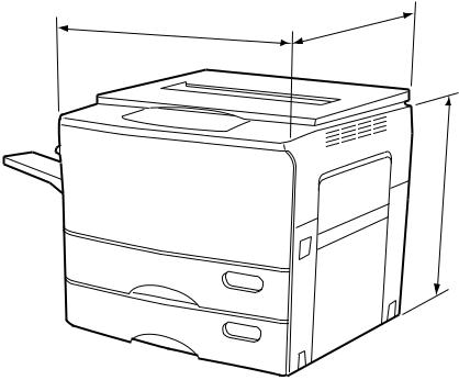
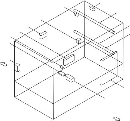
Machine size
598mm
640mm
540mm
Dec. 1996 © TOSHIBA |
1 - 3 |
2060, 2860/70 SPECIFICATIONS |
1.2 Accessories
Copy receiving tray |
: |
1 pc. |
Operator’s manual |
: |
1 pc. |
Set-up report |
: |
1 pc. |
Drum |
: |
1 pc. |
Developer |
: |
1 bottle |
Toner |
: |
1 pc. |
*Accessories vary according to the destination.
1.3 Options
Automatic duplexing unit: ADU |
MD-5002 |
|
|
Automatic document feeder: ADF |
MR-3006 (RADF), MR-2008 (ADF) |
|
|
Paper feed pedestal: PFP |
KD-1003 (1 cassette), KD-2009 (2 cassettes) |
|
|
Paper feed unit |
MY-1006 |
|
|
Large capacity feeder: LCF |
MP-1501 |
|
|
Sorter |
MG-1003A (10 bins) |
|
MG-1004 (10 bins staple) |
|
MG-2009 (20 bins) |
|
MG-2010 (20 bins staple) |
|
|
Key copy counter |
MU-8/MU-10 (6 digit) |
|
|
*Options vary according to the destination.
1.4 Supplies
Drum |
OD-2060 |
|
|
Developer |
ZD-2060 |
|
|
Toner |
ZT-2060 |
|
|
2060, 2860/70 SPECIFICATIONS |
1 - 4 |
Dec. 1996 © TOSHIBA |
2.OUTLINE OF THE MACHINE
2.1 Sectional Views and Electrical Parts Location Diagram
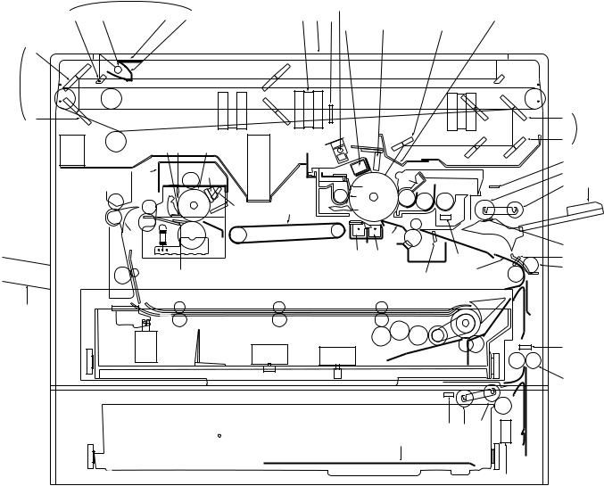
2.1.1Sectional view
[A] Front view
|
1 |
|
|
|
|
|
AS |
|
|
2 5 |
4 3 |
AO AP AN |
|
AM |
|
|
AR |
BK |
AL |
7
6
8 |
|
AT |
|
|
9 |
|
EP ER |
AK |
AQ |
ENEM |
|
|
|
GK |
|
|
|
|
|
DO |
|
FK |
EQ EL |
GT |
|
|
CL |
|
|
CS |
|
|
|
|
BL |
|
|
|
|
DT CP |
|
|
|
|
|
|
|
|
|
|
FR |
|
|
BN |
BM |
|
CK CN |
CO |
|
|
ES |
EK |
CT |
BO |
BR |
|
|
|||
FR |
|
|
|
|
|||||
ES |
|
|
|
|
DS |
|
|
|
|
|
EO |
|
|
|
|
|
|
||
|
FQ |
|
|
BS |
ET |
|
|
|
|
|
|
|
|
|
|
|
CR |
||
|
|
|
|
BQ |
BP |
|
|
|
|
|
|
|
|
|
CM |
|
FL |
||
|
|
FT |
|
|
|
DR |
DP |
DN |
|
|
|
|
|
|
|
||||
|
|
|
|
|
|
|
|
||
|
|
|
FS |
|
|
|
|
|
|
BT |
|
|
|
|
|
|
|
|
|
|
|
|
|
|
|
|
|
|
FM |
|
|
|
|
|
|
|
|
|
DQ |
|
|
|
|
|
|
|
|
|
DK |
|
|
|
CQ |
|
|
|
FN DM |
DL |
|
|
|
|
|
|
FO |
|
|
|
|
|
|
|
|
|
|
|
|
|
|
FP
(This diagram includes an installed ADU. Refer to Chapter 13 concerning the ADU.)
Dec. 1996 © TOSHIBA |
2 - 1 |
2060, 2860/70 GENERAL |
No. |
Name |
No. |
Name |
|
|
|
|
1 |
Carriage 1 |
CQ |
Cassette |
|
|
|
|
2 |
Mirror 1 |
CR |
Manual feed separation pad |
|
|
|
|
3 |
Reflector |
CS |
Manual feed roller |
|
|
|
|
4 |
Light distribution adjustment plates |
DT |
Manual pickup roller |
|
|
|
|
5 |
Exposure lamp |
DK |
Cassette separation roller |
|
|
|
|
6 |
Carriage 2 |
DL |
Cassette feed roller |
|
|
|
|
7 |
Mirror 2 |
DM |
Cassette pickup roller |
|
|
|
|
8 |
Mirror 3 |
DN |
Upper transport roller |
|
|
|
|
9 |
Mirror unit |
DO |
Manual feed switch (S6) |
|
|
|
|
AT |
Mirror 4 |
DP |
Paper guide |
|
|
|
|
AK |
Mirror 5 |
DQ |
Lower transport roller |
|
|
|
|
AL |
Mirror 6 |
DR |
Aligning switch (S8) |
|
|
|
|
AM |
Slit glass |
DS |
Aligning roller (U) |
|
|
|
|
AN |
Auto exposure sensor |
ET |
Aligning roller (L) |
|
|
|
|
AO |
Lens |
EK |
Thermistor-1 (THMS1) |
|
|
|
|
AP |
Original glass |
EL |
Thermostat (THERMO) |
|
|
|
|
AQ |
Ozone filter |
EM |
Heater lamp |
|
|
|
|
AR |
Main charger |
EN |
Heat roller (upper side) |
|
|
|
|
AS |
Discharge lamp |
EO |
Pressure roller (lower side) |
|
|
|
|
BT |
Receiving tray |
EP |
Separation claw (for heat roller) |
|
|
|
|
BK |
LED eraser array |
EQ |
Felt roller |
|
|
|
|
BL |
Main blade |
ER |
Heat roller cleaning blade |
|
|
|
|
BM |
Recovery blade |
ES |
Fuser exit roller |
|
|
|
|
BN |
Toner recovery auger |
FT |
Scraper |
|
|
|
|
BO |
Separation claw (for drum) |
FK |
Fuser cover |
|
|
|
|
BP |
Transfer charger |
FL |
Paper stop switch-1 (S7) |
|
|
|
|
BQ |
Separation charger |
FM |
Paper stop switch-2 (S16) |
|
|
|
|
BR |
Drum |
FN |
Paper-empty switch-2 (S14) |
|
|
|
|
BS |
Bias guide |
FO |
Cassette tray |
|
|
|
|
CT |
Transport belt |
FP |
Cassette size switch-2 (S15) |
|
|
|
|
CK |
Magnetic roller |
FQ |
Exit/ADU selection gate |
|
|
|
|
CL |
Leveller (doctor) |
FR |
Exit roller |
|
|
|
|
CM |
Auto-toner sensor |
FS |
ADU |
|
|
|
|
CN |
Mixer 1 |
GT |
Exit fan (M7) |
|
|
|
|
CO |
Mixer 2 |
GK |
Bottom fan (M8) |
|
|
|
|
CP |
Sheet bypass guide |
|
|
|
|
|
|
2060, 2860/70 GENERAL |
2 - 2 |
Dec. 1996 © TOSHIBA |
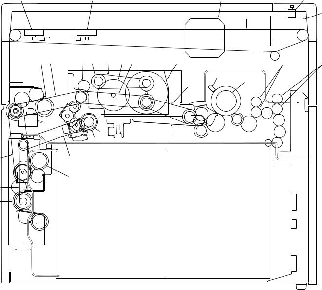
[B] Rear side view
HP |
HO |
IO |
IP |
GP
GQ
IK IT |
HR HT |
HK |
GR HL |
HN |
ES |
FR |
|
|
|
|
|
HQ
EN
HM
HS
CT
GS
IT |
IT |
IN
IM
IL
IN
Dec. 1996 © TOSHIBA |
2 - 3 |
2060, 2860/70 GENERAL |
No. |
Name |
|
|
GP |
Scanning motor (M2) |
|
|
GQ |
Carriage drive wire |
|
|
GR |
Drum gear |
|
|
GS |
Aligning clutch (CLT2) |
|
|
HT |
Drum driving gear |
|
|
HK |
Drum belt |
|
|
HL |
Belt for dev-unit, ALGN-roller & paper feeding drive |
|
|
HM |
Belt for fuser drive |
|
|
HN |
Main motor (M1) |
|
|
HO |
Lens motor (M3) |
|
|
HP |
Mirror motor (M4) |
|
|
HQ |
Thermistor-2 (THMS2) |
|
|
HR |
Dev-unit drive gear |
|
|
HS |
Aligning roller |
|
|
IT |
Paper feed belt |
|
|
IK |
Manual feed clutch (CLT4) |
|
|
IL |
Transport roller clutch (CLT1) |
|
|
IM |
Transport roller drive belt |
|
|
IN |
Cassette feed clutch (CLT3, 5) |
|
|
IO |
Optical fan (M6,12) |
|
|
IP |
Document motor (M11) |
|
|
2060, 2860/70 GENERAL |
2 - 4 |
Dec. 1996 © TOSHIBA |

2.1.2Electrical parts layout
[A] DC electrical parts (except motors)
1
4
7
BO
AK8
AL
BP
BN
AQ
AT
[Front side]
AS
AP
36 |
BT |
BQ |
|
|
|
2 |
|
BL |
|
|
9
|
CR |
|
|
AM |
|
|
BS |
|
|
5 |
|
|
CL |
|
BK CM |
CN |
|
AR CS |
||
[Rear side] |
||
CP |
|
|
CODTCK |
CT |
BMAN AO
CQ
Dec. 1996 © TOSHIBA |
2 - 5 |
2060, 2860/70 GENERAL |
No. |
Name |
No. |
|
Name |
|
||||
|
|
|
|
|
1 |
Control panel key PC board (PWA-KEY) |
*BK |
|
Paper-empty switch-1 (EMP1-SW) (S3) |
|
|
|
|
|
2 |
Display PC board (PWA-DSP) |
BL |
|
Exit switch (EXIT-SW) (S9) |
|
|
|
|
|
3 |
Liquid crystal module (LCD) |
BM |
|
Heat-roller thermistor 1 (THMS1-HTR) |
|
|
|
|
|
4 |
Total counter (T-CTR) |
BN |
|
Toner sensor (TNR-ATC) |
|
|
|
|
|
5 |
Logic PC board (PWA-LGC) |
BO |
|
Lens switch (LNS-SW) (S11) |
|
|
|
|
|
6 |
Auto paper sensor-2 (APS-R) |
BP |
|
Mirror switch (MRR-SW) (S12) |
|
|
|
|
|
7 |
Auto paper sensor-3 (APS-C) |
BQ |
|
Automatic exposure PC board (PWA-AES) |
|
|
|
|
|
8 |
Auto paper sensor-4 (APS-F) |
BS |
|
Aligning-roller clutch (RGT0-CLT) (CLT2) |
|
|
|
|
|
9 |
Toner-full switch (T-FUL-SW) (S13) |
CT |
|
Transport-roller clutch (RGT1-CLT) (CLT1) |
|
|
|
|
|
*AT |
Size switch 1 (SIZE1-SW) (S5) |
CK |
|
Manual-feed roller clutch (MFED-CLT) (CLT4) |
|
|
|
|
|
AK |
Discharge lamp PC board (PWA-ERS) |
*CL |
|
Feed-roller clutch 1 (FED1-CLT) (CLT3) |
|
|
|
|
|
AL |
LED eraser array PC board (K-DCH) |
CM |
|
Size switch 2 (SIZE2-SW) (S15) |
|
|
|
|
|
AM |
High-voltage power supply (PS-HVT) |
CN |
|
Feed-roller clutch 2 (FED2-CLT) (CLT5) |
|
|
|
|
|
AN |
Home switch (HOME-SW) (S10) |
CO |
|
Paper-empty switch 2 (EMP2-SW) (S14) |
|
|
|
|
|
AO |
Platen switch (PTN-SW) (S27) |
CP |
|
Paper stop switch 2 (PSTP2-SW) (S16) |
|
|
|
|
|
AP |
Manual feed switch (M-FED-SW) (S6) |
CQ |
|
Heat-roller thermistor-2 (THMS2-HTR) |
|
|
|
|
|
AQ |
Aligning switch (PSTPO-SW) (S8) |
CR |
|
Drum thermistor (DRM-THMS) |
|
|
|
|
|
AR |
Paper stop switch 1 (PSTP1-SW) (S7) |
*CS |
|
Tray-up switch (T-UP1-SW) (S28) |
|
|
|
|
|
AS |
Side door switch (U-COV-SW) (S4) |
DT |
|
Tray-up switch (T-UP2-SW) (S29) |
|
|
|
|
|
BT |
Auto paper sensor-1 (APS-3B) |
|
|
|
|
|
|
|
|
*: Option
2060, 2860/70 GENERAL |
2 - 6 |
Dec. 1996 © TOSHIBA |

[B] DC electrical parts (motors)
DS
EK
DP
DL
DO
[Front side]
ET
EL
DK
DM
DQDN
DR
[Rear side]
No. |
Name |
No. |
Name |
|
|
|
|
DK |
Main motor (MAIN-MOT) (M1) |
*DQ |
Tray-up motor-1 (T-UP1-MOT) (M13) |
|
|
|
|
DL |
Scanning motor (SCN-MOT) (M2) |
DR |
Tray-up motor-2 (T-UP2-MOT) (M14) |
|
|
|
|
DM |
Lens motor (LNS-MOT) (M3) |
DS |
Optical fan-F (OPT-FAN-F) (M12) |
|
|
|
|
DN |
Mirror motor (MRR-MOT) (M4) |
ET |
Optical fan-R (OPT-FAN-R) (M6) |
|
|
|
|
DO |
Toner motor (TNR-MOT) (M9) |
EK |
Exit fan (EXIT-FAN) (M7) |
|
|
|
|
DP |
Document motor (DCM-MOT) (M11) |
EL |
Bottom fan (BTM-FAN) (M8) |
|
|
|
|
*: Option
Dec. 1996 © TOSHIBA |
2 - 7 |
2060, 2860/70 GENERAL |
[C] AC electrical parts
|
FO |
|
FM |
|
FL |
|
EN |
FK |
ES |
|
|
EP |
EQ |
|
FT
FN
[Front side] |
EO |
EM
ER
[Rear side]
No. |
Name |
No. |
Name |
|
|
|
|
EM |
SW power supply (PS-ACC) |
FT |
Thermostat (Option) |
|
|
|
|
EN |
Door switch (DOOR-SW) (S2) |
FK |
Damp heater U1 (D-HTR-U1) (Option) |
|
|
|
|
EO |
Main switch (MAIN-SW) (S1) |
FL |
Exposure lamp (EXPO-LAMP) |
|
|
|
|
EP |
Lamp regulator PC board (PWA-LRG) |
FM |
Thermofuse (FU-EXPO) |
|
|
|
|
EQ |
Heater lamp (HTR-LAMP) |
FN |
Fuse PC board (PWA-FUS) (Option) |
|
|
|
|
ER |
Damp heater L (D-HTR-L) (Option) |
FO |
Damp heater U2 (D-HTR-U2) (Option) |
|
|
|
|
ES |
Thermostat (K-THERMO) |
|
|
|
|
|
|
2060, 2860/70 GENERAL |
2 - 8 |
Dec. 1996 © TOSHIBA |
2.2 Symbol and Function of Electrical Parts
(1) Motors
Symbol |
Code name |
Function |
Remarks |
Parts list |
||
|
|
|||||
Page |
Item |
|||||
|
|
|
|
|||
|
|
|
|
|
|
|
M1 |
MAIN-MOT (Main motor) |
Drives the drum, developer, |
IC motor |
10 |
31 |
|
|
|
heat roller and transport belt |
|
|
|
|
|
|
|
|
|
|
|
M2 |
SCN-MOT (Scanning motor) |
Scans the optical system |
Pulse motor |
5 |
23 |
|
|
|
|
|
|
|
|
M3 |
LNS-MOT (Lens motor) |
Drives the lens unit |
Pulse motor |
11 |
23 |
|
|
|
|
|
|
|
|
M4 |
MRR-MOT (Mirror motor) |
Drives the mirror unit |
Pulse motor |
11 |
23 |
|
|
|
|
|
|
|
|
M6 |
OPT-FAN-R (Optics fan-R) |
Cools the optical system |
IC motor: Z80 |
5 |
8 |
|
|
|
|
|
|
|
|
M7 |
EXIT-FAN (Exit-fan) |
Cools the drum and cleaner |
IC motor: Z80 |
4 |
14 |
|
|
|
|
|
|
|
|
M8 |
BTM-FAN (Bottom fan) |
Prevents the paper from floating |
IC motor: Z80 |
4 |
14 |
|
|
|
up through suction |
|
|
|
|
|
|
|
|
|
|
|
M9 |
TNR-MOT (Toner motor) |
Replenishes the toner |
Brush motor |
23 |
30 |
|
|
|
|
|
|
|
|
M11 |
DCM-MOT (Document motor) |
Drives copy-area indicators |
Pulse motor |
9 |
2 |
|
|
|
|
|
|
|
|
M12 |
OPT-FAN-F (Optical fan-F) |
Cools the optical system |
IC motor: Z80 |
4 |
14 |
|
|
|
|
|
|
|
|
M13 |
T-UP1-MOT (Tray-up motor-1) |
Drives the upper cassette tray to |
Brush motor |
12 |
36 |
|
|
|
lift up/down |
|
|
|
|
|
|
|
|
|
|
|
M14 |
T-UP2-MOT (Tray-up motor-2) |
Drives the lower cassette tray to |
Brush motor |
12 |
36 |
|
|
|
lift up/down |
|
|
|
|
|
|
|
|
|
|
|
(2) Electromagnetic spring clutches
|
|
|
|
|
Parts list |
||
Symbol |
Code name |
Function |
Remarks |
|
|
|
|
Page |
Item |
||||||
|
|
|
|
|
|||
|
|
|
|
|
|
||
CLT1 |
RGT1-CLT |
Transmits transport-roller drive. |
|
13 |
40 |
||
|
(Transport-roller clutch) |
|
|
|
|
|
|
|
|
|
|
|
|
||
CLT2 |
RGT0-CLT |
Transmits aligning-roller drive. |
|
15 |
16 |
||
|
(Aligning-roller clutch) |
|
|
|
|
|
|
|
|
|
|
|
|
||
CLT3 |
FED1-CLT |
Transmits feed-roller clutch |
|
12 |
24 |
||
|
(Feed-roller clutch-1) |
drive. (Upper cassette) |
|
|
|
|
|
|
|
|
|
|
|
||
CLT4 |
MFED-CLT |
Transmits manual-feed roller |
|
14 |
17 |
||
|
(Manual-feed roller clutch) |
clutch drive. |
|
|
|
|
|
|
|
|
|
|
|
||
CLT5 |
FED2-CLT |
Transmits feed-roller clutch |
|
12 |
24 |
||
|
(Feed-roller clutch-2) |
drive. (Lower cassette) |
|
|
|
|
|
|
|
|
|
|
|
|
|
(3) Counters
|
|
|
|
Parts list |
||
Symbol |
Code name |
Function |
Remarks |
|
|
|
Page |
Item |
|||||
|
|
|
|
|||
|
|
|
|
|
|
|
T |
T-CTR (Total counter) |
Total counter |
6-digit |
3 |
23 |
|
|
|
|
|
|
|
|
K |
K-CTR (Key-copy counter) |
Individual counter |
6-digit (option) |
101 |
5 |
|
|
|
|
|
|
|
|
Dec. 1996 © TOSHIBA |
2 - 9 |
2060, 2860/70 GENERAL |
(4) Switches
|
|
|
|
Parts list |
||
Symbol |
Code name |
Function |
Remarks |
|
|
|
Page |
Item |
|||||
|
|
|
|
|||
|
|
|
|
|
|
|
S1 |
MAIN-SW (Main switch) |
Power supply |
Tumbler type |
6 |
3 |
|
|
|
|
|
|
|
|
S2 |
DOOR-SW (Door switch) |
For safety, cancels abnormal |
Push switch |
6 |
4 |
|
|
|
condition |
|
|
|
|
|
|
|
|
|
|
|
S3 |
EMP1-SW |
Detects lack of paper in the upper |
Photointerruptor |
12 |
32 |
|
|
(Paper-empty switch-1) |
cassette |
|
|
|
|
|
|
|
|
|
|
|
S4 |
U-COV-SW |
For safety, detects open/closed |
Push switch |
2 |
27 |
|
|
(Side door switch) |
condition of paper jam release cover |
|
|
|
|
|
|
|
|
|
|
|
S5 |
SIZE1-SW (Size switch-1) |
Detects upper cassette size |
Push switch |
13 |
50 |
|
|
|
|
|
|
|
|
S6 |
M-FED-SW |
Detects manual feeding |
Photointerruptor |
14 |
3 |
|
|
(Manual-feed switch) |
|
|
|
|
|
|
|
|
|
|
|
|
S7 |
PSTP1-SW |
Detects paper in front of the |
Photointerruptor |
13 |
8 |
|
|
(Paper stop switch-1) |
upper transport roller |
|
|
|
|
|
|
|
|
|
|
|
S8 |
PSTP0-SW |
Detects paper in front of the |
Photointerruptor |
15 |
20 |
|
|
(Aligning switch) |
aligning roller |
|
|
|
|
|
|
|
|
|
|
|
S9 |
EXIT-SW (Exit switch) |
Detects exiting paper |
Photointerruptor |
28 |
8 |
|
|
|
|
|
|
|
|
S10 |
HOME-SW (Home switch) |
Detects home position of the |
Photointerruptor |
11 |
8 |
|
|
|
optical system |
|
|
|
|
|
|
|
|
|
|
|
S11 |
LNS-SW (Lens switch) |
Detects home position of the lens |
Photointerruptor |
11 |
8 |
|
|
|
unit |
|
|
|
|
|
|
|
|
|
|
|
S12 |
MRR-SW (Mirror switch) |
Detects home position of the mirror |
Photointerruptor |
11 |
8 |
|
|
|
unit |
|
|
|
|
|
|
|
|
|
|
|
S13 |
T-FUL-SW |
Detects when the used toner bag |
Push switch |
10 |
25 |
|
|
(Toner-full switch) |
is full |
|
|
|
|
|
|
|
|
|
|
|
S14 |
EMP2-SW |
Detects lack of paper in the lower |
Photointerruptor |
12 |
32 |
|
|
(Paper-empty switch-2) |
cassette |
|
|
|
|
|
|
|
|
|
|
|
S15 |
SIZE2-SW |
Detects lower cassette size |
Push switch |
13 |
50 |
|
|
(Size switch-2) |
|
|
|
|
|
|
|
|
|
|
|
|
S16 |
PSTP2-SW |
Detects paper in front of the lower |
Photointerruptor |
2 |
26 |
|
|
(Paper stop switch-2) |
transport roller |
|
|
|
|
|
|
|
|
|
|
|
S27 |
PTN-SW |
Detects open/closed condition of |
Photointerruptor |
5 |
38 |
|
|
(Platen switch) |
the platen cover |
|
|
|
|
|
|
|
|
|
|
|
S28 |
T-UP1-SW |
Detects the position of the upper |
Photointerruptor |
12 |
32 |
|
|
(Tray-up-1 switch) |
cassette tray |
|
|
|
|
|
|
|
|
|
|
|
S29 |
T-UP2-SW |
Detects the position of the lower |
Photointerruptor |
12 |
32 |
|
|
(Tray-up-2 switch) |
cassette tray |
|
|
|
|
|
|
|
|
|
|
|
2060, 2860/70 GENERAL |
2 - 10 |
Dec. 1996 © TOSHIBA |
(5) Heaters and lamps
|
|
|
Remarks |
Parts list |
||
Symbol |
Code name |
Function |
|
|
||
Page |
Item |
|||||
|
|
|
|
|||
|
|
|
|
|
|
|
EXP |
EXPO-LAMP |
Exposes the original |
Halogen lamp |
18 |
13 |
|
|
(Exposure lamp) |
|
300W |
|
|
|
|
|
|
|
|
|
|
HTR |
HTR-LAMP (Heater lamp) |
Fixing |
Halogen lamp |
25 |
6 |
|
|
|
|
900W |
|
|
|
|
|
|
(100V series) |
|
|
|
|
|
|
1100W |
|
|
|
|
|
|
(200V series) |
|
|
|
|
|
|
|
|
|
|
ERS |
ERS-LAMP |
Discharges the drum |
Fuse type |
4 |
12 |
|
|
(Discharge lamp) |
|
|
|
|
|
|
|
|
|
|
|
|
DCH |
DCH-LED |
To interrupt the charge |
LED |
4 |
10 |
|
|
(LED eraser array) |
|
|
|
|
|
|
|
|
|
|
|
|
DHU1 |
D-HTR-U1 (Damp heater U1) |
Keeps optical system warm (option) |
Cement resistor |
102 |
4 |
|
|
|
|
|
|
|
|
DHU2 |
D-HTR-U2 (Damp heater U2) |
Keeps optical system warm (option) |
Cement resistor |
102 |
4 |
|
|
|
|
|
|
|
|
DHL |
D-HTR-L (Damp heater L) |
Keeps the drum and transfer/separation |
Cement resistor |
7 |
30 |
|
|
|
charger case warm (option) |
|
|
|
|
|
|
|
|
|
|
|
(6) PC boards
Symbol |
Code name |
Function |
Remarks |
Parts list |
||
|
|
|||||
Page |
Item |
|||||
|
|
|
|
|||
|
|
|
|
|
|
|
LGC |
PWA-LGC (Logic PC board) |
Controls the entire copier |
|
8 |
15 |
|
|
|
|
|
|
|
|
DSP |
PWA-DSP |
Controls condition displays |
|
3 |
20 |
|
|
(Display PC board) |
|
|
|
|
|
|
|
|
|
|
|
|
KEY |
PWA-KEY |
Controls operation keys |
|
3 |
21 |
|
|
(Key PC board) |
|
|
|
|
|
|
|
|
|
|
|
|
LRG |
PWA-LRG |
Controls exposure lamp |
|
5 |
20 |
|
|
(Lamp regulator PC board) |
|
|
|
|
|
|
|
|
|
|
|
|
DCH |
K-DCH |
Turns on and drives LED during |
|
4 |
10 |
|
|
(LED eraser array PC board) |
reduction |
|
|
|
|
|
|
|
|
|
|
|
ERS |
PWA-ERS |
Discharge lamp |
|
4 |
12 |
|
|
(Discharge lamp PC board) |
|
|
|
|
|
|
|
|
|
|
|
|
AES |
PWA-AES |
Reads dark/light of the original |
|
17 |
37 |
|
|
(Automatic exposure PC board) |
|
|
|
|
|
|
|
|
|
|
|
|
FUS |
PWA-FUS (Fuse PC board) |
Fuse for the damp heater circuit |
|
7 |
31 |
|
|
|
|
|
|
|
|
Dec. 1996 © TOSHIBA |
2 - 11 |
2060, 2860/70 GENERAL |
(7) Transformers
|
|
|
Remarks |
Parts list |
||
Symbol |
Code name |
Function |
|
|
||
Page |
Item |
|||||
|
|
|
|
|||
|
|
|
|
|
|
|
HVT |
PS-HVT (Charging transformer) |
Generates high voltage electricity |
Mono unit type |
7 |
27 |
|
|
|
for charging (negative voltage) |
|
|
|
|
|
(Transfer/separation |
Generates high voltage electricity |
|
|
|
|
|
transformer) |
for transfer/separation and |
|
|
|
|
|
|
developing bias voltage |
|
|
|
|
|
(Transfer bias |
Generates bias voltage to raise |
|
|
|
|
|
transformer) |
transfer efficiency |
|
|
|
|
|
|
|
|
|
|
|
ACC |
PS-ACC |
Power supply for whole copier |
|
8 |
7 |
|
|
(Power supply for all) |
power |
|
|
|
|
|
|
|
|
|
|
|
(8) Others
|
|
|
|
|
Parts list |
|
Symbol |
Code name |
Function |
Remarks |
|
|
|
|
Page |
Item |
||||
|
|
|
|
|
||
|
|
|
|
|
|
|
ATS |
SNR-ATC |
Reads toner density with a magnetic |
|
23 |
33 |
|
|
(Auto-toner sensor) |
sensor |
|
|
|
|
|
|
|
|
|
|
|
THMS1 |
THMS1-HTR |
Detects temperature of the heat roller |
|
26 |
19 |
|
|
(Heat-roller thermistor-1) |
|
|
|
|
|
|
|
|
|
|
|
|
THMS2 |
THMS2-HTR |
Detects the temperature of the heat roller |
|
26 |
27 |
|
|
(Heat-roller thermistor-2) |
end |
|
|
|
|
|
|
|
|
|
|
|
THERMO |
K-THERMO |
Prevents abnormal heating of heat roller |
|
26 |
8 |
|
|
(Thermostat) |
|
|
|
|
|
|
|
|
|
|
|
|
FU |
FU-EXPO (Thermofuse) |
Prevents abnormal heating of the |
|
18 |
12 |
|
|
exposure lamp |
|
|
|
|
|
|
|
|
|
|
|
|
2060, 2860/70 GENERAL |
2 - 12 |
Dec. 1996 © TOSHIBA |

2.3 Wire Harness Location Diagram
[A] Location diagram
Dec. 1996 © TOSHIBA |
2 - 13 |
2060, 2860/70 GENERAL |

[B] Location diagram for lower unit
2060, 2860/70 GENERAL |
2 - 14 |
Dec. 1996 © TOSHIBA |

Return Skip
3560/70 S/M
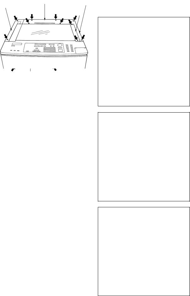
2.4 Removal of Covers and PC Boards
2.4.1Removal of covers
[A] Front cover
(1)Open the front cover.
(2)Remove the pins on the hinges at both ends (1 each).
[B] Upper rear cover
(1) Remove the 4 screws.
[C] Lower rear cover
(1)Remove the upper 3 screws.
(2)Loosen the lower 2 screws.
[D] Upper feed cover
(1)Open the front cover and the bypass tray and then remove the 2 screws.
[E] Feed cover (left and right)
(1)Remove the paper feed cover.
(2)When removing the left feed cover, open the front cover.
(3)Remove the screws (2 on each side).
Front cover
Upper rear cover
Upper feed cover
Left
feed |
Lower |
|
rear |
||
cover |
||
cover |
||
|
||
Right feed cover |
|
|
|
Loosen |
Dec. 1996 © TOSHIBA |
2 - 15 |
2060, 2860/70 GENERAL |
Return Skip
3560/70 S/M
[F] Upper exit cover
(1)Remove the 2 screws.
(2)Open the front cover and remove the screw.
[G] Lower exit cover
(1)Lift the upper unit.
(2)Remove the 5 screws.
[H] Rear top cover
(1)Remove the original cover.
(2)Remove the 4 screws.
[I]Right top cover (feed side)
(1) Remove the 2 screws.
[J]Left top cover (exit side)
(1) Remove the 2 screws.
[K] Glass fix
(1) Remove the 2 screws.
[L] Upper inner cover
(1)Remove the process unit.
(2)Remove the 3 screws.
Upper exit cover
Lower exit cover
|
Rear top cover |
Left top cover |
Right top cover |
|
Glass fix |
Upper inner cover
2060, 2860/70 GENERAL |
2 - 16 |
Dec. 1996 © TOSHIBA |

Return Skip
3560/70 S/M
[M] Middle inner cover
(1) Remove the screw.
[N] Door switch cover
(1) Remove the 2 screws.
[O] Lower inner cover
(1)Remove the toner box.
(2)Remove the middle inner cover.
(3)Remove the 1 screw.
Middle inner cover
Door switch cover
Lower inner cover
Dec. 1996 © TOSHIBA |
2 - 17 |
2060, 2860/70 GENERAL |
Return Skip
3560/70 S/M
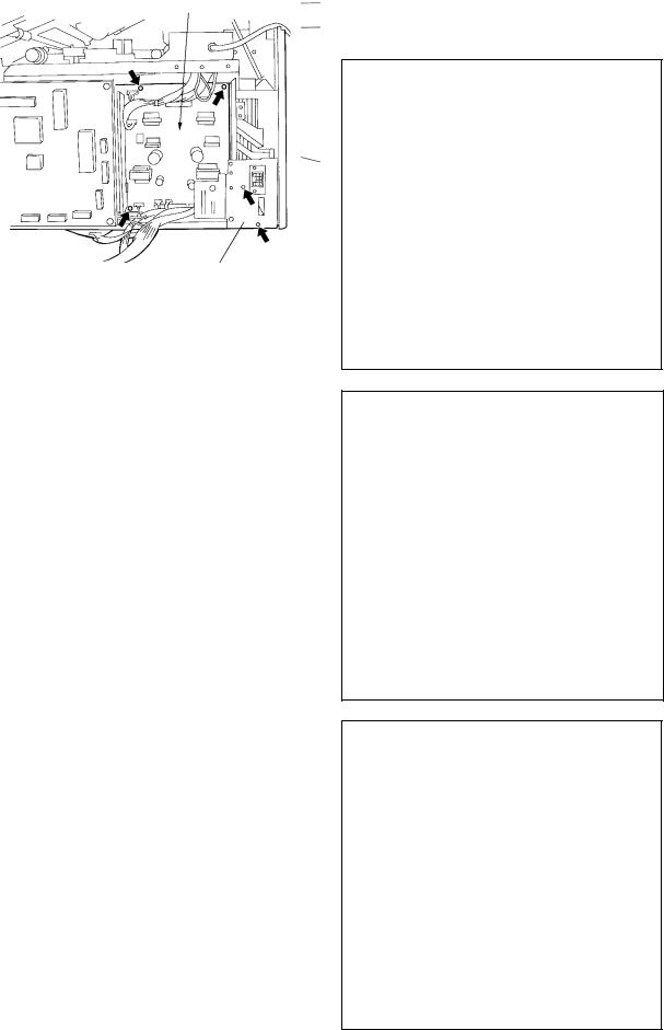
2.4.2Removal of main PC boards
[A] Logic PC board (PWA-LGC)
(1)Remove the lower rear cover.
(2)Remove the 16 connectors (2860). (15 connectors for 2060).
(3)Remove the lock supports (4 pcs.)
(4)Remove the logic PC board.
Lock support PWA-LGC |
Lock support |
[B] Power supply PC board (PS-ACC)
(1)Remove the connector bracket (2 screws).
(2)Remove the 14 connectors.
(3)Remove the 4 screws.
(4)Remove the power supply PC board.
PS-ACC
Connector bracket
[C] Lamp regulator PC board (PWA-LRG) |
|
|
(1) Remove the upper rear cover. |
Lock support |
PWA-LRG |
|
|
(2)Remove the 2 connectors.
(3)Remove the lamp regulator PC board (4 lock supports).
Lock support
Connectors
2060, 2860/70 GENERAL |
2 - 18 |
Dec. 1996 © TOSHIBA |

Return Skip
3560/70 S/M
[D] ADU drawer connector
(1)Remove the logic PC board.
(2)Remove the bracket for the logic PC board (3 screws).
Remove the connector J535 on the PS-ACC.
(3)Remove the bracket for the ADU drawer connector (2 screws).
Bracket for PWA-LGC
ADU drawer connector bracket
Dec. 1996 © TOSHIBA |
2 - 19 |
2060, 2860/70 GENERAL |
Return Skip
3560/70 S/M
3.COPYING PROCESS
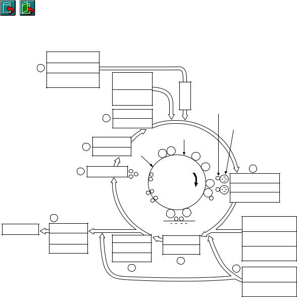
3.1 Copying Process
|
Original exposure |
|
|
2 |
Halogen lamp |
|
|
|
300 W |
LED eraser array |
Optical section |
|
|
63 LEDs |
|
|
|
|
|
|
|
Charging |
Toner |
|
|
|
1
|
|
|
|
–635V ±5 V |
|
|
|
|
Carrier |
|
|
9 |
Discharge lamp |
_ |
_ |
|
|
|
|
|
|
1.8W x 9 lamps |
_ |
|
|
||||
|
|
|
|
|
|||||
|
|
|
|
|
|
|
|||
|
|
|
|
|
|
|
_ |
|
3 |
|
8 |
|
Cleaning |
+ |
|
|
|
|
|
|
|
|
|
|
|
|
|||
|
|
|
|
+ + |
|
|
_ |
+ |
Black development |
|
|
|
|
|
|
|
|||
|
|
|
|
|
|
|
_ |
+ |
Magnetic roller |
|
|
|
|
|
|
|
+ |
|
Bias –100 VDC |
|
7 |
|
|
|
|
_ |
_ |
|
|
|
|
|
|
|
+ |
+ |
|
Sheet-bypass feeding |
|
|
|
|
|
|
|
|
|
|
|
Paper exiting |
Fixing |
|
|
|
|
|
|
|
(50 sheets) |
|
|
|
|
|
|
|
|
|
|
|
Heat roller |
|
|
Separation |
|
Transfer |
|
Cassette feeding (upper/ |
|
|
|
|
|
|
lower/PFP)(600 sheets) |
||||
|
900 W (115V) |
|
|
AC 3.41 kV |
|
|
|
|
|
|
|
|
|
–DC 5.25 kV |
|
LCF feeding |
|||
|
1030W (220/240V) |
|
|
|
|
|
|||
|
|
|
|
1 kHz |
|
|
5 |
|
(1500 sheets) |
|
|
|
|
|
|
|
|
|
|
|
|
|
|
6 |
|
|
|
|
4 |
|
|
|
|
|
|
|
|
|
Transfer bias |
|
|
|
|
|
|
|
|
|
–DC 990 V |
1 Charging |
: Negatively charges surface of |
Dthe photosensitive drum.
2 Exposure |
: Forms an electrical image on |
Dthe drum.
3 Development :  toner adheres to surface of
photosensitive drum and forms
D
a visible image.
4 Transfer bias : Increases transfer efficiency.
D |
|
5 Transfer |
: Transfers the visible image from |
|
the drum onto the transfer |
|
(copy) sheet. |
6 |
Separation |
: Separates the transfer sheet, |
|
D |
along with the toner, from the |
|
drum. |
|
|
|
|
7 |
Fixing |
: Fixes the toner on the transfer |
|
D |
sheet by applying heat and |
|
pressure. |
|
|
|
|
8 |
Cleaning |
: Mechanically removes any re- |
Dmaining toner on the drum.
9 Discharge lamp : Discharges any remaining charge from the drum.
Dec. 1996 © TOSHIBA |
3 - 1 |
2060, 2860/70 PROCESS |

Return Skip
3560/70 S/M
3.2 Comparison with the 2050 of Copying Process Conditions
|
Process |
|
2050 |
2060/2860 |
|||||
|
|
||||||||
|
|
|
|
|
|
|
|
|
|
1. Drum |
|
OD-1710 (OPC ø60) |
OD-2060 (OPC ø60) |
||||||
|
|
|
|
|
|
|
|
|
|
(1) |
Sensitivity |
|
Highly sensitized drum |
(1) |
|
|
|
|
|
|
|
|
|||||||
|
|
|
|
|
|
|
|
|
|
(2) |
Charger grid voltage |
|
DC –800V |
(2)–635 V DC |
|||||
|
|
|
Scolotron system |
Scolotron system |
|||||
|
|
|
|
Output adjustable by using the |
|||||
|
|
|
|
ten keys |
|||||
|
|
|
|
|
|
|
|
|
|
2. Main charger |
|
Variable output (fixed current) using |
|
|
|
|
|
|
|
|
|
|
|
|
|
||||
|
|
|
the digital keys |
|
|
|
|
|
|
|
|
|
|
|
|
|
|
|
|
3. Exposure |
|
|
|
|
|
|
|
|
|
(1) |
Light control |
|
Automatic exposure/manual |
(1)Automatic exposure and |
|||||
|
|
|
slide volume setting |
|
manual 9-step setting |
||||
|
|
|
|
|
|
|
|
|
|
(2) |
Light source |
|
300W halogen lamp stabilized with |
(2) |
|
|
|
|
|
|
|
|
|
||||||
|
|
|
regulator (light intensity remains |
|
|
|
|
|
|
|
|
|
constant even when voltage varies) |
|
|
|
|
|
|
|
|
|
|
|
|
|
|
|
|
4. Development |
|
|
|
|
|
|
|
|
|
(1) |
Magnetic roller |
|
One magnetic roller (with two shaft |
(1) |
|
|
|
|
|
|
|
|
|
||||||
|
|
|
mixers) |
|
|
|
|
|
|
|
|
|
|
|
|
|
|
|
|
(2) Auto-toner |
|
Magnetic bridge-circuit system |
(2) |
|
|
|
|
||
|
|
|
|
||||||
|
|
|
|
|
|
|
|
|
|
(3) |
Toner replenishment |
|
Toner cartridge system |
(3) |
|
|
|
|
|
|
|
|
|
||||||
|
|
|
|
|
|
|
|
|
|
(4) |
Toner-empty detection |
|
Intensity sensing system |
(4) |
|
|
|
|
|
|
|
|
|
||||||
|
|
|
|
|
|
|
|
|
|
(5) Toner |
|
T-1710 (Black) |
(5)T-2060 (Black) |
||||||
|
|
|
T-1710-R (Red) |
|
|
|
|
|
|
|
|
|
T-1710-BL (Blue) |
|
|
|
|
|
|
|
|
|
|
|
|
|
|||
(6) |
Developing material |
|
D-1710 (Black) |
(6)D-2060 (Black) |
|||||
|
|
|
D-1710-R (Red) |
|
|
|
|
|
|
|
|
|
D-1710-BL (Blue) |
|
|
|
|
|
|
|
|
|
|
|
|
|
|||
(7) |
Developer bias |
|
–194V DC, volume adjustable |
(7)–100 V DC, adjustable using the |
|||||
|
|
|
|
|
digital keys |
||||
|
|
|
|
|
|
||||
5. Transfer bias |
|
–1.4KV DC |
–990 V DC |
||||||
|
|
|
|
|
|
|
|
|
|
6. Transfer |
|
Adjustable output (fixed current) using |
|
|
|
|
|
|
|
|
|
|
|
|
|
||||
|
|
|
the digital keys |
|
|
|
|
|
|
|
|
|
|
|
|
|
|
|
|
7. Separation |
|
Adjustable output (independently |
|
|
|
|
|
|
|
|
|
|
|
|
|
||||
|
|
|
adjustable using the digital keys) |
|
|
|
|
|
|
|
|
|
|
|
|
|
|
|
|
2060, 2860/70 PROCESS |
3 - 2 |
Dec. 1996 © TOSHIBA |

Return Skip
3560/70 S/M
|
Process |
2050 |
2060/2860 |
||||
|
|
|
|
|
|
|
|
8. Discharge |
|
|
|
|
|
|
|
(1) |
Discharging position |
Discharge by exposure after cleaning |
(1) |
|
|
|
|
|
|
|
|||||
|
|
|
|
|
|
|
|
(2) |
Discharge lamp |
Discharge by tungsten lamp |
(2) |
|
|
|
|
|
|
|
|||||
|
|
|
|
|
|
|
|
9. Cleaning |
|
|
|
|
|
|
|
(1) |
System |
Blade system |
(1) |
|
|
|
|
|
|
|
|||||
|
|
|
|
|
|
|
|
(2) |
Recovered toner |
Non-reusable |
(2) |
|
|
|
|
|
|
|
|||||
|
|
|
|
|
|
|
|
10. Fixing |
|
|
|
|
|
|
|
(1) |
System |
Long-life heat roller system |
(1) |
|
|
|
|
|
|
|
|||||
|
• Fixing |
• Fixing roller: Teflon coated roller |
• Fixing roller: |
||||
|
|
|
Aluminum roller coated with |
||||
|
|
|
Teflon (ø40) |
||||
|
|
|
|
|
|
||
|
• Pressure |
• Pressure roller: PFA tube silicon |
• Pressure roller: |
||||
|
|
roller (ø28) |
Silicon rubber roller with |
||||
|
|
|
PFA tube. (ø35) |
||||
|
|
|
|
|
|
||
|
• Lamp rating |
Infrared heat |
Infrared heat |
||||
|
|
• 900W (100V series) |
• 900W (115V) |
||||
|
|
• 1100W (200V series) |
• 1030W (220/240V) |
||||
|
|
|
|
|
|
|
|
(2) |
Cleaning |
Cleaning with silicon impregnated |
(2) |
|
|
|
|
|
|
|
|||||
|
|
roller |
|
|
|
|
|
|
|
|
|
|
|
|
|
(3) |
Heater-temperature control |
ON/OFF control by thermistor |
(3) |
|
|
|
|
|
|
|
|||||
|
|
|
|
|
|
|
|
11. Control |
Microcomputer |
|
|
|
|
|
|
|
|
|
|
|
|||
|
|
|
|
|
|
|
|
Dec. 1996 © TOSHIBA |
3 - 3 |
2060, 2860/70 PROCESS |

Return Skip
3560/70 S/M
4.COPIER OPERATION
4.1 Operation Outline
Copier operation |
|
|
Operation during warm up and standby |
|||
|
|
|||||
|
|
|
|
|
|
Automatic-feed copying using PRINT key |
|
|
|
|
|
|
|
|
|
|
Copying operation |
|
|
Bypass-feed copying |
|
|
|
|
|
||
|
|
|
|
|
|
Interrupt copying |
|
|
|
|
|
|
|
4.2 Description of Operation
4.2.1Operation up to standby state after power on
(1)Initial operation
•The main switch is turned ON.
•Copy quantity indicator “0” and “WAIT WARMING UP” are displayed.
•Initialization of the optical system
~Carriages move to their home position and then stop.
~Lens and mirror units move to their home position and then stop.
~Indicators perform the initial operation and move to a position indicating the copy area.
•Initialization of the paper feed section
~Each slot’s cassette trays move upward. If they were raised already, they are not moved.
(2)Pre-running
65 sec. have elapsed since the power was turned ON ~
Main motor rotates ~ Fuser unit drive section rotates: Pre-running
Pressure roller is warmed
After pre-running for 15 sec., the main motor stops
~Fuser unit drive section stops
(3)When the heat roller temperature is sufficient for fixing, the heater lamp is turned off, and the copier enters the standby mode.
4.2.2Standby (ready)
•Bottom fan motor (M8) and exit fan motor (M7) are running at low speed.
•All keys on the control panel are operable.
When there is no key input for a set amount of time, the copy quantity “1” will be shown, the reproduction ratio will indicate “actual size”, and the exposure will be set at automatic.
Dec. 1996 © TOSHIBA |
4 - 1 |
2060, 2860/70 OPERATION |
 Loading...