


SERVICE HANDBOOK 4560/70
PLAIN PAPER COPIER
Click the Page Only button to close the overview area of the window.
Click the Bookmarks and Page button to open the Contents and display bookmarks created for the document. Click a bookmark’s name to go to the Page marked by that bookmark.
Click the Thumbnails and Page button to open the overview area and display thumbnail images of each document page. Click a thumbnail to go to the page marked by that thumbnail.
Copyright TOSHIBA CORPORATION 1995
ALL RIGHTS RESERVED
GENERAL PRECAUTIONS REGARDING THE INSTALLATION AND SERVICE FOR THE COPIER 4560/4570
The installation and service should be done by a qualified service technician.
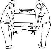
1.Transportation/Installation
•When transporting/installing the copier, use two persons and be sure to use the positions as indicated below.
The copier is fairly heavy and weighs approximately 95 kg (210 lb), therefore pay full attention when handling it.
2.Installation
•Be sure to use a dedicated outlet with AC 115V/15A (220V, 230V, 240V/10A) or more for its power source.
•The copier must be grounded for safety. Never ground it to a gas pipe or a water pipe.
•Select a suitable place for installation.
Avoid excessive heat, high humidity, dust, vibration and direct sunlight.
•Also provide proper ventilation as the copier emits a slight amount of ozone.
•To insure adequate working space for the copying operation, keep a minimum clearance of 80 cm (32”) on the left, 80 cm (32”) on the right and 10 cm (4”) in the rear.
•After having installed the copier, be sure to push the carrying handles into the copier and fasten them with screws.
3.Service of Machines
•Basically, be sure to turn the main switch off and unplug the power cord during service.
•Be sure not to touch high-temperature sections such as the exposure lamp, the fuser unit, the damp heater and their periphery.
•Be sure not to touch high-voltage sections such as the chargers and the high-voltage transformer.
•Be sure not to touch rotating/operating sections such as gears, belts, pulleys, fans, etc.
•When servicing the machines with the main switch turned on, be sure not to touch live sections such as the lamp terminal, etc. and rotating/operating sections.
•Use suitable measuring instruments and tools.

4.Main Service Parts for Safety
•The breaker, door switch, fuse, thermostat, thermofuse, thermistor, etc. are particularly important for safety. Be sure to handle/install them properly.
5.Cautionary Labels
•During servicing be sure to check the rating plate and the cautionary labels such as “Unplug the power cord during service”, “Hot area” etc. to see if there is any dirt on their surface or whether they are properly stuck to the copier.
6.Disposition of Consumable Parts/Packing Materials
•Regarding the recovery and disposal of the copier, supplies, consumable parts and packing materials, it is recommended to follow the relevant local regulations or rules.
7.When parts are disassembled, reassembly is basically the reverse of disassembly unless otherwise noted in this manual or other related documents. Be careful not to reassemble small parts such as screws, washers, pins, E-rings, toothed washers in the wrong places.
8.Basically, the machine should not be operated with any parts removed or disassembled.
9.Precautions Against Static Electricity
•The PC board must be stored in an anti-electrostatic bag and handled carefully using a wristband, because the ICs on it may become damaged due to static electricity.
Caution: Before using the wrist band, pull out the power cord plug of the copier and make sure that there is no uninsulated charged objects in the vicinity.
Copyright 1997
Toshiba Corporation

1.ADJUSTMENT ITEMS
1.1Error Codes
When either the CLEAR PAPER ( ) or CALL SERVICE (
 ) symbol appears, press the CLEAR/ STOP and “8” keys simultaneously and the corresponding error code will be displayed. To clear the error code, turn OFF the machine.
Group |
Error code |
Machine status |
|
|
|
|
|
Transporting jam at the copier |
E01 |
Paper jam inside the copier |
|
|
|
|
|
|
E02 |
Paper jam near the fuser unit |
|
|
|
|
|
|
E03 |
Paper remaining inside the machine when power is on |
|
|
|
|
|
|
E04 |
The front cover is opened during copying |
|
|
|
|
|
|
E05 |
Paper jam near the aligning roller |
|
|
|
|
|
|
E08 |
Paper jam at the stacking area inside the ADU |
|
|
|
|
|
Paper feeding jam |
E11 |
Paper feeding jam at the ADU |
|
|
|
|
|
|
E12 |
Manual feeding jam |
|
|
|
|
|
|
E13 |
Cassette feeding or transporting jam (1st |
cassette) |
|
|
|
|
|
E14 |
Cassette feeding or transporting jam (2nd |
cassette) |
|
|
|
|
|
E15 |
Cassette feeding or transporting jam (3rd |
cassette) |
|
|
|
|
|
E16 |
Cassette feeding or transporting jam (4th |
cassette) |
|
|
|
|
|
E17 |
Cassette feeding or transporting jam (5th |
cassette) |
|
|
|
|
|
E19 |
Paper feeding or transporting jam at the LCF |
|
|
|
|
|
Paper transporting jam at the |
E21 |
Paper jam at the transport route 1 (LCF) |
|
|
|
|
|
feeding units |
E22 |
Paper jam at the transport route 2 (Copier) |
|
|
|
|
|
|
E23 |
Paper jam at the transport route 3 (Aligning) |
|
|
|
|
|
|
E25 |
Paper jam at the transport route 4 (PFP) |
|
|
|
|
|
Original transporting jam at the |
E71 |
Original feeding jam |
|
|
|
|
|
ADF |
E72 |
Original transporting jam |
|
|
|
|
|
|
E73 |
Original exiting jam |
|
|
|
|
|
|
E75 |
2nd original feeding jam (2 in 1) |
|
|
|
|
|
Paper transporting jam at the |
E81 |
Copy paper arrival time is over |
|
|
|
|
|
sorter |
E82 |
Copy paper staying time is over |
|
|
|
|
|
|
E83 |
Sorter early arrival jam |
|
|
|
|
|
|
E84 |
Paper remaining inside the sorter when power is on |
|
|
|
|
|
|
E85 |
Joint open jam while copying |
|
|
|
|
|
|
E88 |
Paper jam outside the sorter bin |
|
|
|
|
|
Service call by the drive system |
C01 |
Abnormal operation of the copier main motor |
|
|
|
|
|
|
C04 |
Abnormal operation of the PFP main motor |
|
|
|
|
|
|
C05 |
Abnormal operation of the ADU main motor |
|
|
|
|
|
Nov. 1997 © TOSHIBA CORP. |
1 - 1 |
4560/4570 ADJUSTMENT |
Group |
Error code |
Machine status |
|
|
|
Service call by the paper feeding |
C11 |
Abnormal operation of the ADU side motor |
|
|
|
system |
C12 |
Abnormal operation of the ADU end motor |
|
|
|
|
C13 |
Abnormal operation of the upper cassette tray |
|
|
|
|
C14 |
Abnormal operation of the lower cassette tray |
|
|
|
|
C15 |
Abnormal operation of the PFP upper cassette tray |
|
|
|
|
C16 |
Abnormal operation of the PFP middle cassette tray |
|
|
|
|
C17 |
Abnormal operation of the PFP lower cassette tray |
|
|
|
|
C18 |
Abnormal operation of the LCF tray |
|
|
|
Service call by the optical system |
C21 |
Carriage initializing error |
|
|
|
|
C22 |
Lens initializing error |
|
|
|
|
C23 |
Mirror initializing error |
|
|
|
|
C26 |
Exposure lamp burn-out detected |
|
|
|
Service call by the process system |
C33 |
Easy set-up is failed |
|
|
|
|
C35 |
Developer material exists at the transfer/separation adjustment |
|
|
|
Fuser unit area |
C41 |
Abnormal thermistor or heater disconnection when power is on |
|
|
|
|
C43 |
Warming up mode after disconnection judgement, or abnor- |
|
|
mal thermistor after copier is ready |
|
|
|
|
C44 |
Warming up mode after disconnection judgement, or heater |
|
|
disconnection after copier is ready |
|
|
|
|
C45 |
Sub thermistor is abnormal |
|
|
|
Service call by communication |
C54 |
Sorter — Main CPU communication error |
|
|
|
|
C55 |
ADF — Main CPU communication error |
|
|
|
|
C56 |
PFC — Main CPU communication error |
|
|
|
|
C64 |
Main CPU — PNL communication error |
|
|
|
Service call by ADF |
C72 |
Poor adjustment by the aligning sensor detected |
|
|
|
|
C73 |
EEROM poorly initialized |
|
|
|
|
C74 |
Poor adjustment by the exit/reserve sensor detected |
|
|
|
Service call by sorter |
C80 |
Sorter power abnormal |
|
|
|
|
C81 |
Paper transport motor abnormal |
|
|
|
|
C82 |
Bin shifting motor abnormal |
|
|
|
|
C83 |
Upper limit error |
|
|
|
|
C84 |
Lower limit error |
|
|
|
|
C85 |
Home sensor error |
|
|
|
|
C86 |
Staple guide bar drive motor abnormal |
|
|
|
|
C87 |
Staple drive motor abnormal |
|
|
|
|
C88 |
Copy removal sensor error |
|
|
|
|
C89 |
Sorter push bar motor abnormal |
|
|
|
Service call by the other |
C93 |
ADF original stop signal not received |
|
|
|
Note: If there is a possibility of the heater malfunctioning as a consequence of the short-circuiting of the TRIAC, the microcomputer will check for abnormal temperature and send out error code “C44” and turn OFF the main switch of the copier.
4560/4570 ADJUSTMENT |
1 - 2 |
Nov. 1997 © TOSHIBA CORP. |
1.2Self-Diagnosis Modes
Mode |
Input |
Definition |
Cleaning |
Display after selection |
||||
code |
method |
|||||||
|
|
|
|
|
|
|||
All-LEDs-lit |
“01” |
All LEDs on the control panel are lit. |
C/S |
|
|
|
|
|
|
|
|
|
|
|
|
|
|
|
|
|
|
|
|
|
|
|
Aging mode |
“02” |
Aging (RADF does not operate) |
“09” |
AGING |
|
|||
|
|
|
|
|
|
|
100% |
|
|
|
|
|
|
|
|
|
|
Test mode |
“03” |
Motor test and input/output check |
“09” |
|
|
|
CH |
|
|
|
|
|
TEST MODE C |
100% |
|||
|
|
|
|
|
|
|
|
|
Test mode |
“04” |
Motor test and input/output check |
“09” |
|
|
|
CH |
|
|
|
|
|
TEST MODE C |
100% |
|||
|
|
|
|
|
|
|
|
|
Adjustment |
“05” |
Adjustment of items |
“09” |
|
|
|
AJ |
|
mode |
|
|
|
TEST MODE A |
100% |
|||
|
|
|
|
|
|
|
|
|
Forced ready |
“06” |
Forced entry of ready mode |
– |
|
|
|
|
|
mode |
|
|
|
|
|
|
|
|
|
|
|
|
|
|
|
||
|
|
|
|
|
|
|
|
|
Aging mode |
“07” |
Aging (includes RADF) |
“09” |
AGING |
|
|||
|
|
|
|
|
|
|
100% |
|
|
|
|
|
|
|
|
|
|
Setting mode |
“08” |
System switch over and setting of each |
“09” |
|
|
|
AD |
|
|
|
priority mode, PM counter, etc. |
|
TEST MODE D |
100% |
|||
|
|
|
|
|
|
|
|
|
Note: To access the desired diagnostic mode, turn ON the power switch while pressing the appropriate keys.
<Procedure>
•All-LEDs-lit mode (01):
•Aging mode (02 or 07):
0 |
1 |
PWR |
|
|
|
|
|
|
All LEDs light |
|
|
|
|
|
C/S |
|
|
|
Exit |
||||||||||
|
|
|
|
|
|
|
|
|
|
|
|
|
|||||||||||||||||
|
|
|
|
|
|
|
|
|
|
|
|
|
|
|
|
|
|
|
|
|
|
|
|
|
|||||
0 |
2 |
PWR |
|
|
|
|
|
|
Aging |
|
|
|
|
C/S |
|
|
|
|
0 9 |
|
|
Exit |
|||||||
|
|
|
|
|
|
|
|
|
|
|
|
|
|
|
|
|
|||||||||||||
0 |
7 |
|
|
|
|
|
|
|
|
|
|
|
|
|
|
|
|
|
|
|
|
|
|
|
|
|
|
|
|
|
|
|
|
|
|
|
|
|
|
|
|
|
|
|
|
|
|
|
|
|
|
|
|
||||||
|
|
|
|
|
|
|
|
|
|
|
|
|
|
|
|
|
|
|
|
|
|
|
|
||||||
•Test mode (03 or 04): For these test modes, refer to 1.2.1 and 1.2.2.
•Adjustment mode (05): For this mode, refer to “1.2.3 Adjustment mode”.
• Forced ready mode (06): |
PWR |
|
|
0 6 |
|
|
Forced ready |
|
|
Note: This mode is for checking the paper feeding operation only.
• Setting mode (08): For this mode, refer to “1.2.4 Setting mode”.
Notes: C/S: Press the CLEAR/STOP key
PWR: Turn ON the power switch
INT: Press the INTERRUPT key
E/S: Press the ENERGY SAVER key
Nov. 1997 © TOSHIBA CORP. |
1 - 3 |
4560/4570 ADJUSTMENT |
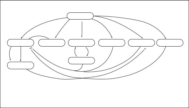
Quick reference chart for self-diagnostic mode
Normal |
|
Power ON |
|
|
|
|
|
|
“01” |
“02” |
“07” |
“03/04” |
“05” |
“08” |
|
|
*2 |
|
(With ADF) |
|
|
|
|
|
“C” |
|
|
|
|
|
|
Warming up |
All the displays on |
Aging |
Test mode |
Adjustment mode |
Setting mode |
||
the control panel lit |
|||||||
“06” |
|
“P” |
“C” |
“09” |
“09” |
|
“09” |
|
|
|
|
|
|
||
|
|
Stops momentarily |
|
|
“05” |
|
|
Standby |
|
|
|
|
|
|
|
|
|
“09” |
|
|
|
|
|
|
*1 |
|
|
|
|
|
|
|
|
|
|
|
|
|
|
*“P”: PRINT key ON.
“C”: CLEAR/STOP key ON.
*1 When the copier is in the adjustment mode which you entered by turning on the power switch while pressing keys “0” and “5” simultaneously, pressing keys “0” and “9” simultaneously will make the copier exit into the standby mode. Only in this standby mode, can you access the adjustment mode repeatedly by simply entering “0” and “5”.
*2 While all the displays on the control panel are lit (“01” mode), copying is not possible.
When the copier is made to enter the standby status by pressing the CLEAR/STOP key, copying is enabled.
4560/4570 ADJUSTMENT |
1 - 4 |
Nov. 1997 © TOSHIBA CORP. |
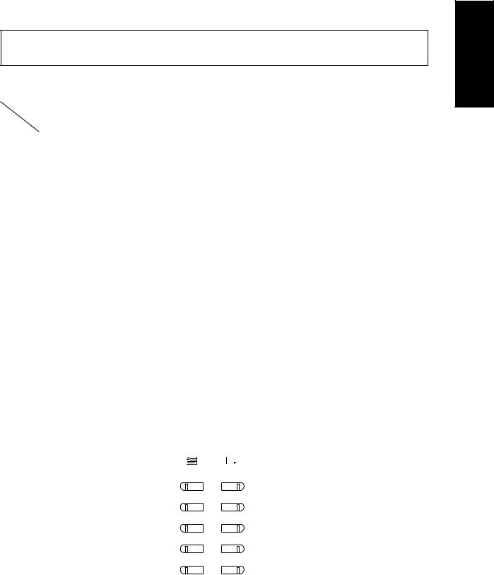
1.2.1Input signal check (Test mode 03/04)
In the “03” or “04” test mode, the following input signal conditions can be checked by pressing the
appropriate keys.
[A] When automatic exposure is selected
Indicator |
|
Original size LED |
|
|
Copy size LED |
|
|
|||
Key LED |
|
|
|
|
|
|
|
|
Unit |
|
A4/LD |
A3/LG |
B4/LT |
A5/ST |
A4/LD |
A3/LG |
B4/LT |
A5/ST |
|||
operation |
|
|||||||||
|
|
|
|
|
|
|
|
|
||
[1] Key |
PLTNSW |
PLL-OK |
MRRSW |
LNZSW |
PSTPSW |
|
|
|
|
|
|
Closed |
Main motor |
Mirror home |
Lens home |
Paper found |
– |
– |
– |
|
|
|
|
rotation NG |
position |
position |
|
|
|
|
|
|
|
|
|
|
|
|
|
|
|
|
|
[2] Key |
|
|
|
EXITSW |
|
APSR |
APSC |
APSF |
|
|
|
– |
– |
– |
Paper found |
– |
Rear sensor has |
Center sensor has |
Front sensor has |
|
|
|
|
|
|
|
|
not found original |
not found original |
not found original |
Copier |
|
|
|
|
|
|
|
|
|
|
||
[3] Key |
|
|
|
DFCNT |
SCNT |
DEVSW |
TFULSW |
|
||
|
|
|
|
|
||||||
|
– |
– |
– |
DF |
Sorter |
Dev unit |
Not toner |
– |
|
|
|
|
|
|
not installed |
not installed |
not loaded |
full |
|
|
|
|
|
|
|
|
|
|
|
|
|
|
[4] Key |
HOMESW |
|
HTRDY |
|
|
APS2 |
APS1 |
APS0 |
|
|
|
Carriage |
– |
Heater |
– |
– |
Original |
Original |
Original |
|
|
|
home position |
|
ON |
|
|
not found |
not found |
not found |
|
|
|
|
|
|
|
|
|
|
|
|
|
[5] Key |
|
Size width |
|
Size width |
Empty |
Open |
Exit |
Aligning |
|
|
|
– |
sensor 2 |
– |
sensor 1 |
sensor |
sensor |
sensor |
sensor |
ADF |
|
|
|
ON |
|
ON |
ON |
ON |
ON |
ON |
|
|
|
|
|
|
|
|
|
|
|
|
|
[6] Key |
|
|
Copy removal |
Limit |
Bin home |
One-rotation |
Tray paper |
Entrance |
|
|
|
– |
– |
sensor |
sensor |
sensor |
detecttion sensor |
detecttion sensor |
sensor |
Sorter |
|
|
|
|
ON |
ON |
ON |
ON |
ON |
ON |
|
|
|
|
|
|
|
|
|
|
|
|
|
LED lit in above condition (Signal level : H)
ORGINAL COPY
A4/LD
A3/LG
B4/LT
A5/ST
UNIVERSAL/OTHER
Nov. 1997 © TOSHIBA CORP. |
1 - 5 |
4560/4570 ADJUSTMENT |
[B] When manual exposure is selected
Indicator |
|
Original size LED |
|
|
Copy size LED |
|
|
|||
Key LED |
|
|
|
|
|
|
|
|
Unit |
|
A4/LD |
A3/LG |
B4/LT |
A5/ST |
A4/LD |
A3/LG |
B4/LT |
A5/ST |
|||
operation |
|
|||||||||
|
|
|
|
|
|
|
|
|
|
|
[1] Key |
|
TUPCL |
PEMPCL |
PSTPCL |
UCVDOR |
|
|
PSTPCU |
|
|
|
– |
Copier |
Copier |
Copier |
U-turn cover |
– |
– |
Copier |
Copier |
|
|
lower cassette |
lower cassette |
lower cassette |
upper cassette |
||||||
|
|
|
|
|
|
|
|
|
||
|
|
tray top position |
paper empty |
PSTP-SW ON |
opened |
|
|
PSTP-SW ON |
|
|
|
|
|
|
|
|
|
|
|
|
|
[2] Key |
SBFSW |
|
LC-KEY |
LC-CNT |
LCDOR |
TDWNLC |
TUPLC |
PEMPLC |
|
|
|
Manual feed |
– |
LCF tray |
LCF not |
LCF |
LCF tray |
LCF tray |
LCF |
Copier |
|
|
|
|||||||||
|
paper empty |
|
down key OFF |
installed |
door opened |
bottom SW ON |
top SW ON |
paper empty |
LCF |
|
|
|
|
|
|
|
|
|
|
|
|
[3] Key |
|
TUPPF2 |
PEMPPF2 |
PSTPPF2 |
|
TUPPF1 |
PEMPPF1 |
PSTPPF1 |
|
|
|
– |
Pedestal |
Pedestal |
Pedestal |
– |
Pedestal |
Pedestal |
Pedestal |
|
|
|
middle cassette |
middle cassette |
middle cassette |
upper cassette |
upper cassette |
upper cassette |
|
|||
|
|
|
|
|||||||
|
|
tray top position |
paper empty |
PSTP-SW ON |
|
tray top position |
paper empty |
PSTP-SW ON |
PFP |
|
|
|
|
|
|
|
|
|
|
||
[4] Key |
|
PPLL-OK |
PF-CNT |
PFDOR |
|
TUPPF3 |
PEMPPF3 |
PSTPPF3 |
||
|
|
|
||||||||
|
– |
Pedestal motor |
Pedestal |
PFP side |
– |
Pedestal |
Pedestal |
Pedestal |
|
|
|
lower cassette |
lower cassette |
lower cassette |
|
||||||
|
|
|
|
|
|
|
||||
|
|
rotating NG |
not installed |
door opened |
|
tray top position |
paper empty |
PSTP-SW ON |
|
|
|
|
|
|
|
|
|
|
|
|
|
[5] Key |
|
AD-CNT |
APLL-OK |
SIDSW |
ENDSW |
PJAM1AD |
|
PEMPAD |
|
|
|
– |
ADU not |
ADU motor |
ADU side |
ADU end |
ADU JAM SW |
– |
ADU inside |
ADU |
|
|
|
installed |
rotating NG |
guide home |
guide home |
Paper present |
|
Paper present |
|
|
|
|
SW ON |
SW ON |
|
|
|||||
|
|
|
|
|
|
|
|
|||
[6] Key |
|
|
|
|
SIZCL3 |
SIZCL2 |
SIZCL1 |
SIZCL0 |
|
|
|
– |
– |
– |
– |
Copier |
Copier |
Copier |
Copier |
Copier |
|
|
lower cassette |
lower cassette |
lower cassette |
lower cassette |
||||||
|
|
|
|
|
||||||
|
|
|
|
|
SIZE SW OFF |
SIZE SW OFF |
SIZE SW OFF |
SIZE SW OFF |
|
|
|
|
|
|
|
|
|
|
|
|
|
[7] Key |
SIZPF33 |
SIZPF32 |
SIZPF31 |
SIZPF30 |
SIZPF23 |
SIZPF22 |
SIZPF21 |
SIZPF20 |
|
|
|
Pedestal |
Pedestal |
Pedestal |
Pedestal |
Pedestal |
Pedestal |
Pedestal |
Pedestal |
|
|
|
upper cassette |
upper cassette |
upper cassette |
upper cassette |
middle cassette |
middle cassette |
middle cassette |
middle cassette |
|
|
|
SIZE SW OFF |
SIZE SW OFF |
SIZE SW OFF |
SIZE SW OFF |
SIZE SW OFF |
SIZE SW OFF |
SIZE SW OFF |
SIZE SW OFF |
PFP |
|
|
|
|
|
|
|
|
|
|
||
[8] Key |
SIZPF13 |
SIZPF12 |
SIZPF11 |
SIZPF10 |
|
|
|
|
||
|
|
|
|
|
||||||
|
Pedestal |
Pedestal |
Pedestal |
Pedestal |
– |
– |
– |
– |
|
|
|
lower cassette |
lower cassette |
lower cassette |
lower cassette |
|
|||||
|
SIZE SW OFF |
SIZE SW OFF |
SIZE SW OFF |
SIZE SW OFF |
|
|
|
|
|
|
|
|
|
|
|
|
|
|
|
|
|
LED lit in above condition (Signal level : H)
ORGINAL COPY
A4/LD
A3/LG
B4/LT
A5/ST
UNIVERSAL/OTHER
4560/4570 ADJUSTMENT |
1 - 6 |
Nov. 1997 © TOSHIBA CORP. |
<Procedure>
0 3 |
|
|
|
|
|
|
|
|
AUTO-EXP |
|
|
|
|
|
|
|
|
|
|||
|
|
|
|
|
|
|
|
EXP |
|
|
|
Digital key |
|
|
|
LED ON |
|
|
|
0 9 |
|
|
|
|
|
|
|
|
|
|
|
|
|
|
|
|
|
||||||
PWR |
|
|
|
|
|
|
|
|
|
|
|
|
|
|
|
|
|
|
|
|
(To clear) |
|
|
|
|
|
|
|
|
|
|
|
|
|
|
|
|
|
|
|
|
|
|
|
|
|
|
|
|
|
|
|
|
|
|
|
|
|
|
|
|
|
|
|
|
Note: 03 With initialization before test mode is entered 04
 Without initialization
Nov. 1997 © TOSHIBA CORP. |
1 - 7 |
4560/4570 ADJUSTMENT |
1.2.2Output signal check (03/04)
In the “03” or “04” test mode, the following output signal conditions can be checked by entering appro-
priate codes.
|
Code |
Function |
|
|
Code |
|
Function |
Group |
|
|
|
|
|
|
|
|
|
|
1 |
Main motor |
ON |
|
11 |
|
OFF |
1 |
|
|
|
|
|
|
|
|
|
|
2 |
Feed motor |
ON |
|
12 |
|
OFF |
1 |
|
|
|
|
|
|
|
|
|
|
3 |
Aligning motor |
ON |
|
13 |
|
OFF |
1 |
|
|
|
|
|
|
|
|
|
|
6 |
Toner motor |
ON |
|
16 |
|
OFF |
1 |
|
|
|
|
|
|
|
|
|
|
7 |
Optical fan |
ON |
|
17 |
|
OFF |
1 |
|
|
|
|
|
|
|
|
|
|
8 |
Exit fan/ACC fan |
ON |
|
18 |
|
OFF |
1 |
|
|
|
|
|
|
|
|
|
|
10 |
Total counter |
|
Increases at each “P” key press. |
|
2 |
||
|
|
|
|
|
|
|
|
|
|
20 |
Scanning motor |
|
At 1st “P” key press, scans forward and backward at 2nd press. |
2 |
|||
|
|
|
|
|
|
|
|
|
|
21 |
Lens motor |
|
At 1st “P” key press, moves to 50% position and to 200% position |
2 |
|||
|
|
|
|
at 2nd press. |
|
|
||
|
|
|
|
|
|
|
|
|
|
22 |
Mirror motor |
|
At 1st “P” key press, moves to 50% position and to 200% position |
2 |
|||
|
|
|
|
at 2nd press. |
|
|
||
|
|
|
|
|
|
|
|
|
|
24 |
Document motor |
|
At 1st “P” key press, moves to 50% position and to 200% position |
2 |
|||
|
|
|
|
at 2nd press. |
|
|
||
|
|
|
|
|
|
|
|
|
|
30 |
Charge output |
|
At 1st “P” key press, comes ON and goes OFF at 2nd press. |
3 |
|||
|
|
|
|
|
|
|
|
|
|
31 |
Transfer output |
|
At 1st “P” key press, comes ON and goes OFF at 2nd press. |
3 |
|||
|
|
|
|
|
|
|
|
|
|
32 |
Separation output |
|
At 1st “P” key press, comes ON and goes OFF at 2nd press. |
3 |
|||
|
|
|
|
|
|
|
|
|
*1 |
33 |
Exposure lamp |
|
At 1st “P” key press, comes ON and goes OFF at 2nd press. |
3 |
|||
|
|
|
|
|
|
|
|
|
|
34 |
Pre-transfer bias |
|
At 1st “P” key press, comes ON and goes OFF at 2nd press. |
3 |
|||
|
|
|
|
|
|
|
|
|
|
37 |
Separation claw solenoid |
|
At 1st “P” key press, comes ON and goes OFF at 2nd press. |
3 |
|||
|
|
|
|
|
|
|
|
|
|
39 |
Copier lower transport roller clutch |
|
At 1st “P” key press, comes ON and goes OFF at 2nd press. |
3 |
|||
|
|
|
|
|
|
|
|
|
|
40 |
Copier upper cassette tray motor |
|
Tray only rises. |
|
3 |
||
|
|
|
|
|
|
|
||
|
41 |
Copier upper cassette feed roller clutch |
At 1st “P” key press, comes ON and goes OFF at 2nd press. |
3 |
||||
|
|
|
|
|
|
|
||
|
42 |
Copier upper transport roller clutch |
At 1st “P” key press, comes ON and goes OFF at 2nd press. |
3 |
||||
|
|
|
|
|
|
|
|
|
|
43 |
Copier lower cassette tray motor |
|
Tray only rises. |
|
3 |
||
|
|
|
|
|
|
|
||
|
44 |
Copier lower cassette feed roller clutch |
At 1st “P” key press, comes ON and goes OFF at 2nd press. |
3 |
||||
|
|
|
|
|
|
|
|
|
|
45 |
ADU stopper end motor |
|
Reciprocates at each “P” key press. |
|
2 |
||
|
|
|
|
|
|
|
|
|
|
46 |
ADU side end motor |
|
Reciprocates at each “P” key press. |
|
2 |
||
|
|
|
|
|
|
|
|
|
|
47 |
ADU feed roller clutch |
|
At 1st “P” key press, comes ON and goes OFF at 2nd press. |
3 |
|||
|
|
|
|
|
|
|
|
|
|
48 |
ADU stack clutch |
|
At 1st “P” key press, comes ON and goes OFF at 2nd press. |
3 |
|||
|
|
|
|
|
|
|
|
|
|
49 |
PFP upper cassette tray motor |
|
Tray only rises. |
|
3 |
||
|
|
|
|
|
|
|
||
|
50 |
PFP upper cassette feed roller clutch |
At 1st “P” key press, comes ON and goes OFF at 2nd press. |
3 |
||||
|
|
|
|
|
|
|
|
|
|
51 |
PFP transport clutch |
|
At 1st “P” key press, comes ON and goes OFF at 2nd press. |
3 |
|||
|
|
|
|
|
|
|
|
|
|
52 |
PFP middle cassette tray motor |
|
Tray only rises. |
|
3 |
||
|
|
|
|
|
|
|
||
|
53 |
PFP middle cassette feed roller clutch |
At 1st “P” key press, comes ON and goes OFF at 2nd press. |
3 |
||||
|
|
|
|
|
|
|
|
|
*1 The exposure lamp stays on for 5 sec., then goes OFF automatically.
4560/4570 ADJUSTMENT |
1 - 8 |
Nov. 1997 © TOSHIBA CORP. |

Code |
Function |
|
|
Code |
Function |
Group |
|
|
|
|
|
|
|
|
|
|
|
54 |
PFP lower cassette tray motor |
|
Tray only rises. |
|
3 |
|
|
|
|
|
|
|
|
|
|
|
|
55 |
PFP lower cassette feed roller clutch |
At 1st “P” key press, comes ON and goes OFF at 2nd press. |
3 |
|
|
|||
|
|
|
|
|
|
|
|
|
56 |
Manual feed roller clutch |
|
At 1st “P” key press, comes ON and goes OFF at 2nd press. |
3 |
|
|
||
|
|
|
|
|
|
|
|
|
57 |
LCF tray motor |
|
At 1st “P” key press, rises to the limit and goes down at 2nd press. |
2 |
|
|
||
|
|
|
|
|
|
|
|
|
58 |
LCF feed motor |
|
At 1st “P” key press, comes ON and stops at 2nd press. |
3 |
|
|
||
|
|
|
|
|
|
|
|
|
59 |
ADU stack gate solenoid |
|
At 1st “P” key press, starts and goes OFF at 2nd press. |
3 |
|
|
||
|
|
|
|
|
|
|
|
|
60 |
ADU motor |
ON |
|
70 |
OFF |
1 |
|
|
|
|
|
|
|
|
|
|
|
61 |
PFP main motor |
ON |
|
71 |
OFF |
1 |
|
|
|
|
|
|
|
|
|
|
|
65 |
Developer fan |
ON |
|
75 |
OFF |
1 |
|
|
|
|
|
|
|
|
|
|
|
66 |
Copier transport roller clutch |
ON |
|
76 |
OFF |
1 |
|
|
|
|
|
|
|
|
|
|
|
80 |
DF independent aging |
|
At 1st “P” key press, comes ON and stops at 2nd press. |
3 |
|
|
||
|
(single side operation) |
|
|
|
|
|
|
|
|
|
|
|
|
|
|
|
|
81 |
DF independent aging |
|
At 1st “P” key press, comes ON and stops at 2nd press. |
3 |
|
|
||
|
(double side operation) |
|
|
|
|
|
|
|
|
|
|
|
|
|
|
|
|
82 |
DF pick-up roller rotation |
|
At 1st “P” key press, comes ON and stops at 2nd press. |
3 |
|
|
||
|
|
|
|
|
|
|
|
|
83 |
DF aligning roller rotation |
|
At 1st “P” key press, comes ON and stops at 2nd press. |
3 |
|
|
||
|
|
|
|
|
|
|
|
|
84 |
DF transport belt rotation (CW) |
|
At 1st “P” key press, comes ON and stops at 2nd press. |
3 |
|
|
||
|
|
|
|
|
|
|
|
|
85 |
DF transport belt rotation (CCW) |
|
At 1st “P” key press, comes ON and stops at 2nd press. |
3 |
|
|
||
|
|
|
|
|
|
|
|
|
90 |
Sorter transport motor ON |
|
At 1st “P” key press, comes ON and stops at 2nd press. |
3 |
|
|
||
|
(403 mm/sec) |
|
|
|
|
|
|
|
|
|
|
|
|
|
|
|
|
91 |
Sorter bin motor ON (bins move |
|
At 1st “P” key press, comes ON and stops at 2nd press. |
3 |
|
|
||
|
up and down after initialization.) |
|
|
|
|
|
|
|
|
|
|
|
|
|
|
|
|
92 |
Sorter aging without paper |
|
At 1st “P” key press, starts and goes OFF at 2nd press. |
3 |
|
|
||
|
|
|
|
|
|
|
|
|
<Procedure> Group (1)
|
|
|
|
|
|
|
|
|
|
|
|
|
|
|
|
|
|
|
|
|
|
|
03/04 |
|
|
|
|
|
|
|
|
|
Operation |
|
|
Stop |
|
|
|
|
|
|
|
|
|
PWR |
|
|
|
Code |
|
|
|
|
(ON) |
|
|
code |
|
|
|
|
|
09 |
|
Warm-up |
||
|
|
|
|
|
|
|
|
|
|
|
|
|
|
|
|
|
|
|
|
|||
|
|
|
|
|
|
|
|
|
|
|
|
|
|
|
|
|
|
|
|
|
|
|
Group (2)
|
|
|
|
|
|
|
|
|
|
|
|
|
|
|
|
|
|
|
|
|
|
Test mode standby |
|
|
|
|
|
|
|
|
|
|
|
|
|
|
|
|
|
|
|
|
|
|
|
|
|
|
|
|
|
|
|
|
|
|
|
|
|
|
|
|
C/S |
|
|
|
||
03/04 |
|
|
|
|
|
|
|
|
|
|
Operation |
|
|
|
|
|
|
|
|
|||
|
|
|
|
Code |
|
|
|
|
|
(ON) |
|
|
|
|
|
|
|
|
|
|
|
|
PWR |
|
|
|
|
|
|
|
|
|
|
|
|
|
|
|
|
|
|
Warm-up |
|||
|
|
|
|
|
|
|
|
|
|
|
|
|
|
|
09 |
|
|
|
|
|||
|
|
|
|
|
|
|
|
|
|
|
|
|
|
|
|
|
|
|
|
|||
|
|
|
|
|
|
|
|
|
|
|
|
|
|
|
|
|
|
|
|
|
|
|
Group (3)
|
|
|
|
|
|
|
|
|
|
|
|
|
|
|
|
|
|
|
|
|
|
|
|
|
Test mode standby |
03/04 |
|
|
|
|
|
|
|
|
|
|
Operation |
|
|
|
|
|
|
|
|
C/S |
|
|
|
||
|
|
|
|
Code |
|
|
|
|
|
(ON) |
|
|
|
|
|
|
|
|
|
|
|
|
|
||
PWR |
|
|
|
|
|
|
|
|
|
|
|
|
|
|
|
|
|
|
|
|
Warm-up |
||||
|
|
|
|
|
|
|
|
|
|
|
|
|
|
|
|
|
|
|
09 |
|
|
|
|
||
|
|
|
|
|
|
|
|
|
|
|
|
|
|
|
|
|
|
|
|
|
|
|
|
|
|
Nov. 1997 © TOSHIBA CORP. |
1 - 9 |
4560/4570 ADJUSTMENT |

1.2.3Adjustment mode (05)
In this mode, the following adjustment items can be corrected or changed (see the Adjustment Code List for “05” Mode). To access this code, turn ON the power while pressing the “0” and “5” keys.
|
Adjustment item |
Code |
Key to adjust with |
Key to store with |
Remarks |
|
|
|
|
|
|
*2 |
Auto-toner sensor |
0 |
Zoom keys |
INTERRUPT |
See 1.3 for details. |
|
|
|
|
|
|
|
Exposure |
1–17 |
Zoom keys |
INTERRUPT |
See 1.4 for details. |
*3 |
|
|
|
|
|
Automatic adjustment |
49 |
Not needed |
Not needed |
|
|
|
for exposure |
|
|
|
|
|
|
|
|
|
|
|
HVT output |
38–40 |
Zoom keys |
INTERRUPT |
See 1.6 for details. |
|
|
|
|
|
|
|
Registration |
53–59 |
Digital keys |
INTERRUPT |
See 1.5 for details. |
*4 |
|
|
|
|
|
ADF EEPROM initialization and |
97 |
Not needed |
Not needed |
|
|
|
automatic adjustment for ADF sensor |
|
|
|
|
|
|
|
|
|
|
|
Other adjustment |
Except for |
Digital keys |
INTERRUPT |
Refer to Adjustment |
|
|
above codes |
|
|
code list. |
|
|
|
|
|
|
<Procedure>
|
0 |
5 |
|
|
|
|
|
|
|
|
|
|
|
|
|
|
|
|
|
|
|
|
|
|
|
|
|
|
|
|
|
|
|
|
|
|
|
|
0 |
9 |
|
|
|
|
|
|
|
|
|
Code |
|
|
|
|
|
|
|
|
|
|
ADJUST |
|
|
|
INT |
|
|
|
|
|
E/S |
|
|
|
|||||||
|
|
|
|
|
|
|
|
|
|
|
|
|
|
|
|
|
|
|
|
|
|
|
|
|
|
|
||||||||||||||
|
PWR |
|
|
|
|
|
|
|
|
|
|
|
|
|
|
|
|
|
|
|
|
|
|
|
|
Memory set |
|
**Test copy |
Exit |
|||||||||||
*2 |
0 |
5 |
|
|
|
|
|
|
|
|
|
|
|
|
|
|
|
|
|
|
|
|
|
|
|
|
|
|||||||||||||
|
|
|
|
|
|
|
|
|
|
|
|
|
|
|
|
|
|
|
|
|
|
|
|
|
|
|
|
|
|
|
|
|
|
|
|
|
|
|||
|
|
|
|
0 |
|
|
|
|
|
|
|
|
|
Automatic adjustment for Auto-toner |
|
|
|
|
|
|
INT |
|
|
|
0 |
9 |
||||||||||||||
|
|
|
|
|
|
|
|
|
|
|
|
|
|
|
|
|
|
|
|
|
|
|
|
|
|
|||||||||||||||
|
|
|
|
|
|
|
|
|
|
|
|
|
|
|
|
|
|
|
|
|
|
|||||||||||||||||||
|
PWR |
|
|
|
|
|
|
|
|
|
|
|
|
|
|
|
|
|
|
|
|
|
|
|
|
|
|
|
|
|
|
Memory set |
|
Exit |
||||||
|
|
|
|
|
|
|
|
|
|
|
|
|
|
|
|
|
|
|
|
|
|
|
|
|
|
|
|
|
|
|
|
|
|
|
||||||
*3 |
0 |
5 |
|
|
|
|
|
|
|
|
|
|
|
|
|
|
0 9 |
|
|
|
49 |
|
|
|
|
|
|
Automatic adjustment |
|
|
|||||
|
|
|
|
|
|
|
|
|
|
|
|
|
|
||||
|
|
|
|
|
|
|
|
|
|
|
|
|
|||||
|
PWR |
|
|
|
|
|
|
|
|
|
|
|
|
|
|
Exit |
|
|
|
|
|
|
|
|
|
|
|
|
|
||||||
|
|
|
|
|
|
|
|
|
|
|
|
|
|
|
|
|
|
(Possible only after automatic adjustment is finished)
*4 |
0 |
5 |
|
|
|
|
|
|
|
|
|
|
|
ADF EEPROM initialization |
|
|
0 9 |
|
|
|
|
|
97 |
|
|
|
|
|
|
|
|
||||
|
|
|
|
|
|
|
|
|
|
|
|
ADF sensor automatic adjustment |
|
|
|||
|
PWR |
|
|
|
|
|
|
|
|
|
|
|
|
Finished 2 Exit |
|||
|
|
|
|
|
|
|
|
|
|
|
|
|
|
||||
|
|
|
|
|
|
|
|
|
|
|
|
|
|
|
|
||
sec. later
**Duplex copying is not available using the E/S key in the adjustment mode.
4560/4570 ADJUSTMENT |
1 - 10 |
Nov. 1997 © TOSHIBA CORP. |
Adjustment code list (AJ: “05”)
|
Code |
Name |
Allowable |
Initial value* |
|
Remarks |
|
|
No. |
input value |
|
|
|||
|
|
|
|
|
|
||
|
|
|
|
|
|
||
*2 |
0 |
Auto-toner sensor |
– |
– |
About 3 minutes later, this value changes |
||
|
|
|
|
|
automatically |
|
|
|
|
|
|
|
|
||
|
1 |
Manual exposure (100%) |
0–255 |
128 |
The larger the value, the lighter the image. |
||
|
|
|
|
|
|
|
|
|
2 |
Manual exposure (154%) |
0–255 |
128 |
The adjustment sequence must be 1 |
2 |
|
|
|
|
|
|
|
|
|
|
3 |
Manual exposure (50%) |
0–255 |
128 |
3 4 |
5 6 7 8 9 10 |
|
|
|
|
|
|
|
|
|
|
4 |
Manual exposure (200%) |
0–255 |
128 |
|
|
|
|
|
|
|
|
|
|
|
|
5 |
Automatic exposure (100%) |
0–255 |
128 |
|
|
|
|
|
|
|
|
|
|
|
|
6 |
Automatic exposure (154%) |
0–255 |
128 |
|
|
|
|
|
|
|
|
|
|
|
|
7 |
Automatic exposure (50%) |
0–255 |
128 |
|
|
|
|
|
|
|
|
|
|
|
|
8 |
Automatic exposure (200%) |
0–255 |
128 |
|
|
|
|
|
|
|
|
|
||
|
9 |
Allowable exposure step range (light) |
0–255 |
50 |
The larger the value, the lighter the light range. |
||
|
|
|
|
|
|
||
|
10 |
Allowable exposure step range (dark) |
0–255 |
210 |
The larger the value, the darker the dark range. |
||
|
|
|
|
|
|
||
|
14 |
Photo exposure (100%) |
0–255 |
128 |
The larger the value, the lighter the image. |
||
|
|
|
|
|
|
|
|
|
15 |
Photo exposure (154%) |
0–255 |
128 |
The adjustment sequence must be 14 |
15 |
|
|
|
|
|
|
|
|
|
|
16 |
Photo exposure (50%) |
0–255 |
128 |
16 |
17 |
|
|
|
|
|
|
|
|
|
|
17 |
Photo exposure (200%) |
0–255 |
128 |
|
|
|
|
|
|
|
|
|
||
|
20 |
Aligning motor speed adjustment |
0–15 |
8 |
Each increase by “1” causes the lengthwise |
||
|
|
|
|
|
reproduction ratio to increase by 0.1% |
|
|
|
|
|
|
|
|
||
|
21 |
Main motor speed adjustment |
0–15 |
8 |
Each increase by “1” causes the lengthwise |
||
|
|
|
|
|
reproduction ratio to increase by 0.1% |
|
|
|
|
|
|
|
|
||
|
25 |
LED eraser array timing adjustment |
0–15 |
8 |
Each increase by “1” causes the erased |
||
|
|
(100%) |
|
|
position by LED to shift approx. 1.0 mm |
|
|
|
|
|
|
|
|
|
|
|
26 |
LED eraser array timing adjustment |
0–15 |
8 |
toward the trailing edge of the paper. |
|
|
|
|
(200%) |
|
|
The adjustment sequence must be 25 |
26 |
|
|
|
|
|
|
|
|
|
|
27 |
LED eraser array timing adjustment |
0–15 |
8 |
27 |
|
|
|
|
(50%) |
|
|
|
|
|
|
|
|
|
|
|
||
|
30 |
LED eraser array timing adjustment |
0–15 |
8 |
Each increase by “1” causes the erased |
||
|
|
(leading edge) |
|
|
position by LED to shift approx. 1.0 mm |
|
|
|
|
|
|
|
|
|
|
|
31 |
LED eraser array timing adjustment |
0–15 |
8 |
toward the trailing edge. |
|
|
|
|
(trailing edge) |
|
|
|
|
|
|
|
|
|
|
|
||
|
32 |
Editing position adjustment (100%) |
0–15 |
8 |
Each increase by “1” causes the erased |
||
|
|
|
|
|
position by LED to shift approx. 1.0 mm |
|
|
|
|
|
|
|
|
|
|
|
33 |
Editing position adjustment (200%) |
0–15 |
8 |
toward the trailing edge of the paper. |
|
|
|
|
|
|
|
The adjustment sequence must be 32 |
33 |
|
|
|
|
|
|
|
|
|
|
34 |
Editing position adjustment (50%) |
0–15 |
8 |
34 |
|
|
|
|
|
|
|
|
|
|
|
35 |
Leading-edge void adjustment |
0–15 |
0 |
0: No void |
|
|
|
|
|
|
|
|
||
|
36 |
Trailing-edge void adjustment |
0–15 |
0 |
1-15: Void present (approx. 1.0 mm/step) |
||
|
|
|
|
|
|
||
|
38 |
Grid bias output |
0–255 |
128 |
The larger the value, the higher the output. |
||
*5 |
|
|
|
|
|
||
39 |
Transfer transformer output |
0–255 |
128 |
The larger the value, the higher the output. |
|||
*5 |
|
|
|
|
|
||
40 |
Separation transformer output |
0–255 |
128 |
The larger the value, the higher the output. |
|||
|
|
|
|
|
|
||
|
42 |
Grid bias output (photo mode) |
0–255 |
128 |
The larger the value, the higher the output. |
||
|
|
|
|
|
|
||
|
43 |
Developer bias adjustment |
0–255 |
100 |
Use the code 38 in order to check output. |
||
|
|
|
|
|
|
|
|
Nov. 1997 © TOSHIBA CORP. |
1 - 11 |
4560/4570 ADJUSTMENT |
|
Code |
Name |
Allowable |
Initial value* |
|
|
|
Remarks |
|
No. |
input value |
|
|
|
|||
|
|
|
|
|
|
|
||
|
|
|
|
|
|
|||
|
45 |
LCD contrast |
0–255 |
132 |
The larger the value, the lighter the LCD. |
|||
*3 |
|
|
|
|
|
|||
49 |
Automatic adjustment for automatic |
– |
– |
Automatically adjusts the automatic exposure |
||||
|
|
exposure |
|
|
based on the manual exposure. |
|||
|
|
|
|
|
The adjustment sequence must be 1 2 |
|||
|
|
|
|
|
3 |
4 |
49 |
|
|
|
|
|
|
|
|||
|
53 |
Registration (100%, lower cassette) |
0–40 |
20 |
Each increase by “1” causes the image to |
|||
|
|
|
|
|
|
|||
|
54 |
Registration (200%, lower cassette) |
0–15 |
8 |
shift 1.2 mm toward the paper leading edge. |
|||
|
|
|
|
|
|
|||
|
55 |
Registration (50%, lower cassette) |
0–15 |
8 |
The adjustment sequence must be 53 |
|||
|
|
|
|
|
|
|
|
|
|
56 |
Registration (100%, SFB) |
0–15 |
8 |
54 |
55 |
56 |
58. |
|
|
|
|
|
|
|
|
|
|
58 |
Registration (100%, ADU) |
0–15 |
8 |
|
|
|
|
|
|
|
|
|
|
|||
|
60 |
Lens position adjustment (100%) |
0–40 |
20 |
Each increase by “1” moves the lens toward |
|||
|
|
|
|
|
|
|||
|
61 |
Mirror position adjustment (100%) |
0–40 |
20 |
the paper exit side. |
|||
|
|
|
|
|
|
|||
|
62 |
Lens position adjustment (200%) |
0–40 |
20 |
The adjustment sequence must be |
|||
|
|
|
|
|
|
|
|
|
|
63 |
Mirror position adjustment (200%) |
0–40 |
20 |
61 |
60 |
63 |
62 65 64. |
|
|
|
|
|
|
|
|
|
|
64 |
Lens position adjustment (50%) |
0–40 |
20 |
|
|
|
|
|
|
|
|
|
|
|
|
|
|
65 |
Mirror position adjustment (50%) |
0–40 |
20 |
|
|
|
|
|
|
|
|
|
|
|||
|
80 |
Aligning value (lower cassette, long) |
0–31 |
16 |
Each increase by “1” causes the paper to |
|||
|
|
|
|
|
bend more. |
|
||
|
|
|
|
|
(B4, FOLIO, A3, LG, COMPUTER, LD) |
|||
|
|
|
|
|
|
|||
|
81 |
Aligning value (SFB) |
0–31 |
16 |
Each increase by “1” causes the paper to |
|||
|
|
|
|
|
bend more. |
|
||
|
|
|
|
|
|
|||
|
82 |
Aligning value (upper cassette, long) |
0–31 |
16 |
Each increase by “1” causes the paper to |
|||
|
|
|
|
|
bend more. |
|
||
|
|
|
|
|
(B4, FOLIO, A3, LG, COMPUTER, LD) |
|||
|
|
|
|
|
|
|
|
|
|
83 |
Aligning value (ADU, long) |
0–31 |
16 |
|
|
|
|
|
|
|
|
|
|
|||
|
84 |
ADF aligning value (1st page) |
0–15 |
8 |
Each increase by “1” moves the original more |
|||
|
85 |
ADF aligning value (2nd page) |
0–15 |
8 |
toward the DF exit side. |
|||
|
|
|
|
|
|
|||
|
87 |
ADF aligning value (2 in 1 original gap) |
0–15 |
8 |
Each increase by “1” makes the gap between |
|||
|
|
|
|
|
originals increase. |
|||
|
90 |
Auto-toner sensor adjustment value |
0–255 |
128 |
The auto-toner adjustment value is indicated. |
|||
|
|
|
|
|
|
|||
|
92 |
Aligning value (PFP) |
0–31 |
16 |
Each increase by “1” causes the paper to |
|||
|
|
|
|
|
|
|
||
|
93 |
Aligning value (LCF) |
0–31 |
16 |
bend more. |
|
||
|
94 |
Aligning value (lower cassette, short) |
0–31 |
16 |
Each increase by “1” causes the paper to |
|||
|
|
|
|
|
|
|||
|
95 |
Aligning value (upper cassette, short) |
0–31 |
16 |
bend more (A5-R, B5, B5-R, A4, A4-R, ST-R, |
|||
|
|
|
|
|
|
|
||
*4 |
96 |
Aligning value (ADU, short) |
0–31 |
16 |
LT, LT-R). |
|
||
|
97 |
ADF EEPROM Initialization and |
– |
– |
|
|
|
|
|
|
automatic adjustment for ADF sensor |
|
|
|
|
|
|
|
|
|
|
|
|
|||
|
99 |
Red-time clock adjustment |
0–63 |
0 |
1~31: –5.3 sec/month/step |
|||
|
|
|
|
|
33~63: +10.6 sec/month/step |
|||
|
|
|
|
|
0, 32: Correction deactivated |
|||
|
|
|
|
|
|
|
|
|
* Initial value means memory initialization value.
*5 Remove developer for adjustment.
SFB: Stack Feed Bypass
4560/4570 ADJUSTMENT |
1 - 12 |
Nov. 1997 © TOSHIBA CORP. |

1.2.4Setting mode (08)
In this mode, the various special modes listed in the Setting Code List can be set or changed.
<Procedure>
|
|
|
|
|
|
|
|
|
|
|
|
|
|
|
|
|
|
|
|
|
|
|
|
|
|
|
|
|
|
|
|
|
|
|
|
0 |
|
|
8 |
|
|
|
|
|
|
|
|
|
|
|
|
|
Set/change |
|
|
|
|
|
|
|
|
|
|
|
|
|
|
||
|
|
|
|
|
|
|
|
|
|
Code |
|
|
|
|
|
|
a value |
|
|
|
|
|
INT |
|
|
|
|
|
0 |
|
9 |
|
||
|
|
|
|
|
|
|
|
|
|
|
|
|
|
|
|
|
|
|
|
|
|
|
|
|
|
|
||||||||
|
PWR |
|
|
|
|
|
|
|
|
|
|
|
|
|
|
|
Memorize |
|
|
Clear |
||||||||||||||
|
|
|
|
|
|
|
|
|
|
|
|
|
|
|
|
|
|
|
|
|||||||||||||||
|
|
|
|
|
|
|
|
|
|
|
|
|
|
|
|
|
|
|
|
|
|
|
|
|
||||||||||
|
|
|
|
|
|
|
|
|
|
|
|
|
|
|
|
|
|
|
|
|
|
|||||||||||||
|
Code |
|
|
|
Allowable |
|
Initial Value* |
|
|
|
|
|
|
|
Remarks |
|||||||||||||||||||
|
No. |
|
|
|
|
|
|
Name |
|
|
input value |
|
|
|
|
|
|
|
|
|||||||||||||||
|
|
|
|
|
|
|
|
|
|
|
|
|
|
|
|
|
|
|
|
|
|
|
|
|
|
|
|
|
||||||
|
|
|
|
|
|
|
|
|
|
|
|
|
|
|
|
|||||||||||||||||||
|
0 |
|
|
|
|
Date/Time input |
|
|
13 digits |
|
0 |
|
|
|
Year/Month/Date/Day/Hour/Minute/Second |
|||||||||||||||||||
|
|
|
|
|
|
|
|
|
|
|
|
|
|
|
|
|
|
|
||||||||||||||||
|
1 |
|
|
|
|
Date indication |
|
|
|
0–3 |
|
2 |
|
|
|
(Example) |
0: 7/16, |
1: 16/7, 2: Jul. 16, |
||||||||||||||||
|
|
|
|
|
|
|
|
|
|
|
|
|
|
|
|
|
|
|
|
|
|
|
|
|
|
|
|
|
|
3: 16 Jul. |
||||
|
|
|
|
|
|
|
|
|
|
|
|
|
|
|
|
|
||||||||||||||||||
|
2 |
|
|
|
|
Time indication |
|
|
|
0–1 |
|
UC=2 |
|
(Example) |
0: 15:30, |
1: PM3:30 |
||||||||||||||||||
|
|
|
|
|
|
|
|
|
|
|
|
|
|
|
|
|
|
|
|
EUR=0 |
|
|
|
|
|
|
|
|
|
|
|
|||
|
|
|
|
|
|
|
|
|
|
|
|
|
|
|
|
|
||||||||||||||||||
|
4 |
|
|
|
|
Automatic sort mode |
|
|
|
0–3 |
|
0 |
|
|
|
The sort mode is selected automatically when |
||||||||||||||||||
|
|
|
|
|
|
|
|
|
|
|
|
|
|
|
|
|
|
|
|
|
|
|
|
|
the original is placed on the ADF. |
|||||||||
|
|
|
|
|
|
|
|
|
|
|
|
|
|
|
|
|
|
|
|
|
|
|
|
|
0: deactivated, 1: staple/sort, 2: sort, 3: group |
|||||||||
|
|
|
|
|
|
|
|
|
|
|
|
|
|
|
|
|
||||||||||||||||||
|
5 |
|
|
|
|
Automatic duplex mode |
|
|
|
0–3 |
|
1 |
|
|
|
The duplex mode is selected automatically |
||||||||||||||||||
|
|
|
|
|
|
|
|
|
|
|
|
|
|
|
|
|
|
|
|
|
|
|
|
|
when the original is placed on the ADF. |
|||||||||
|
|
|
|
|
|
|
|
|
|
|
|
|
|
|
|
|
|
|
|
|
|
|
|
|
0: deactivated, 1: single-sided to dual-sided, |
|||||||||
|
|
|
|
|
|
|
|
|
|
|
|
|
|
|
|
|
|
|
|
|
|
|
|
|
2: dual-sided to dual-sided, 3: Duplex mode |
|||||||||
|
|
|
|
|
|
|
|
|
|
|
|
|
|
|
|
|
|
|
|
|
|
|
|
|
selection screen |
|
|
|||||||
|
|
|
|
|
|
|
|
|
|
|
|
|
|
|
|
|
||||||||||||||||||
|
7 |
|
|
|
|
Access control mode |
|
|
|
0–1 |
|
0 |
|
|
|
0: deactivated, 1: activated |
||||||||||||||||||
|
|
|
|
|
|
|
|
|
|
|
|
|
|
|
||||||||||||||||||||
|
8 |
|
|
|
|
Version |
|
|
|
0–3 |
|
0–3 |
|
0: EUR, 1: UC, 2: JPN, 3: OTHER |
||||||||||||||||||||
|
|
|
|
|
|
|
|
|
|
|
|
|
|
|
|
|||||||||||||||||||
|
9 |
|
|
|
|
Actual-size reproduction ratio |
|
|
0–1 |
|
0 |
|
|
|
0: 100% (EUR, OTHER), 1: 101% (UC) |
|||||||||||||||||||
|
|
|
|
|
|
|
(the direction of copy movement) |
|
|
|
|
|
|
|
|
|
|
|
|
|
|
|
|
|
|
|
|
|||||||
|
|
|
|
|
|
|
|
|
|
|
|
|
|
|
|
|||||||||||||||||||
|
10 |
|
|
|
|
Timer mode |
|
|
0–10 |
|
3 |
|
|
|
Resetting operation start time is: |
|||||||||||||||||||
|
|
|
|
|
|
|
|
|
|
|
|
|
|
|
|
|
|
|
|
|
|
|
|
|
0: deactivated, 1 to 10: adjustment value x15 |
|||||||||
|
|
|
|
|
|
|
|
|
|
|
|
|
|
|
|
|
|
|
|
|
|
|
|
|
(unit: second) |
|
|
|||||||
|
|
|
|
|
|
|
|
|
|
|
|
|
|
|
|
|
||||||||||||||||||
|
11 |
|
|
|
|
Energy saving |
|
|
|
0–19 |
|
11 |
|
|
|
Energy saving operation start time is: |
||||||||||||||||||
|
|
|
|
|
|
|
|
|
|
|
|
|
|
|
|
|
|
|
|
|
|
|
|
|
0: 3, 1: 5, 2: 10, 3: 15, 4: 20, 5: 25, 6: 30, |
|||||||||
|
|
|
|
|
|
|
|
|
|
|
|
|
|
|
|
|
|
|
|
|
|
|
|
|
7: 40, 8: 50, 9: 60, 10: 70, 11: 80, 12: 90, |
|||||||||
|
|
|
|
|
|
|
|
|
|
|
|
|
|
|
|
|
|
|
|
|
|
|
|
|
13: 100, 14: 110, 15: 120 , 16: 150, 17: 180, |
|||||||||
|
|
|
|
|
|
|
|
|
|
|
|
|
|
|
|
|
|
|
|
|
|
|
|
|
18: 210, 19: 240 (unit: minute) |
|||||||||
|
|
|
|
|
|
|
|
|
|
|
|
|
|
|
|
|||||||||||||||||||
|
12 |
|
|
|
|
MAX. 9 (Maximum multiple copying) |
|
|
0–3 |
|
0 |
|
|
|
0: max.999, 1: max.99, 2: max.9, 3: max.600 |
|||||||||||||||||||
|
|
|
|
|
|
|
|
|
|
|
|
|
|
|
|
|
||||||||||||||||||
|
13 |
|
|
|
|
Paper-feed retrial |
|
|
|
0–1 |
|
0 |
|
|
|
0: feed retrial mode, 1: no-feed-retrial mode |
||||||||||||||||||
|
|
|
|
|
|
|
|
|
|
|
|
|
|
|
|
|
||||||||||||||||||
|
14 |
|
|
|
|
Cassette priority selection |
|
|
|
0–6 |
|
0 |
|
|
|
0: A4/LT, 1: LCF, 2: upper cassette, 3: lower |
||||||||||||||||||
|
|
|
|
|
|
|
|
|
|
|
|
|
|
|
|
|
|
|
|
|
|
|
|
|
cassette, 4: PFP-U, 5: PFP-M, 6: PFP-L |
|||||||||
|
|
|
|
|
|
|
|
|
|
|
|
|
|
|
|
|
||||||||||||||||||
|
15 |
|
|
|
|
Exposure mode |
|
|
|
0–2 |
|
0 |
|
|
|
0: auto, 1: manual, 2: photo |
||||||||||||||||||
|
|
|
|
|
|
|
|
|
|
|
|
|
|
|
|
|
||||||||||||||||||
|
16 |
|
|
|
|
A3/LD double count |
|
|
|
0–1 |
|
0 |
|
|
|
0: single count, 1: double count |
||||||||||||||||||
|
|
|
|
|
|
|
|
|
|
|
|
|
|
|
|
|
||||||||||||||||||
|
17 |
|
|
|
|
Manual-feed auto-start |
|
|
|
0–1 |
|
0 |
|
|
|
0: PRINT key starting, 1: auto-start |
||||||||||||||||||
|
|
|
|
|
|
|
|
|
|
|
|
|
|
|
|
|
|
|
||||||||||||||||
|
18 |
|
|
|
|
Default ADF mode |
|
|
|
0–1 |
|
0 |
|
|
|
0: ADF, 1: SDF |
|
|
||||||||||||||||
|
|
|
|
|
|
|
|
|
|
|
|
|
|
|
|
|
|
|
|
|
|
|
|
|
|
|
|
|
|
|
|
|
|
|
Nov. 1997 © TOSHIBA CORP. |
1 - 13 |
4560/4570 ADJUSTMENT |
Code |
Name |
Allowable |
Initial Value* |
Remarks |
|
No. |
input value |
||||
|
|
|
|||
|
|
|
|
|
|
19 |
Default Sorter mode |
0–3 |
0 |
0: non sort, 1: staple, 2: sort, 3: group |
|
|
|
|
|
|
|
20 |
Default Edge erasing mode |
0–2 |
2 |
0: non edge erasing, 1: Edge erasing, |
|
|
|
|
|
2: Auto edge erasing |
|
|
|
|
|
|
|
21 |
Auto cassette change |
0–1 |
1 |
0: deactivated, 1: activated |
|
|
|
|
|
|
|
22 |
Default APS mode |
0–2 |
1 |
0: manual, 1: APS, 2: AMS |
|
|
|
|
|
|
|
23 |
Detection of manually placed original |
0–1 |
0 |
0: activated, 1: deactivated |
|
|
|
|
|
|
|
25 |
Guide Bias control selection |
0–1 |
0 |
0: activate Guide Bias Control, |
|
|
|
|
|
1: deactivate Guide Bias (always off) |
|
|
|
|
|
|
|
27 |
ADF's APS mode |
0–2 |
0 |
0: detects every original, |
|
|
|
|
|
1: detects only the first original, |
|
|
|
|
|
2: prevents copying blank originals |
|
|
|
|
|
|
|
28 |
Pressing PRINT-KEY after |
0–2 |
0 |
0: accept (copy start), 1: refuse 1st pressing |
|
|
suspension of APS/AMS |
|
|
(accept 2nd pressing), 2: copy disable |
|
|
|
|
|
|
|
31 |
Paper size (LCF) |
0–15 |
3, 4 |
3: LT(UC), 4: A4(EUR, OTHER) |
|
|
|
|
|
|
|
35 |
Cassette/ADU connection |
0–3 |
0 |
0: Auto-detection, 1: cassette, 2: ADU, |
|
|
|
|
|
3: No connection |
|
|
|
|
|
|
|
36 |
PFP connection |
0–4 |
0 |
0: Auto-detection, 1: 1-cassette, 2: 2- |
|
|
|
|
|
cassettes, 3: 3-cassettes, 4: No connection |
|
|
|
|
|
|
|
43 |
Resettable counter display/Original |
0–3 |
0 |
0: deactivated, 1: resettable counter display, |
|
|
counter display |
|
|
2: original counter display, 3: both |
|
|
|
|
|
|
|
44 |
All clear after copy |
0–1 |
0 |
0: deactivated, 1: activated |
|
|
|
|
|
|
|
47 |
Pre-run time setting value |
0–18 |
15 |
0: 0, 1: 5, 2: 10, 3: 15, 4: 20, 5: 25, 6: 30, |
|
|
|
|
|
7: 40, 8: 50, 9: 60, 10: 70, 11: 80, 12: 90, |
|
|
|
|
|
13: 100, 14: 110, 15: 120, 16: 130, 17: 140, |
|
|
|
|
|
18: 150 (unit: second) |
|
|
|
|
|
|
|
48 |
Width of erased area by LED eraser |
0–1 |
0 |
0: overlap image, 1: does not overlap image |
|
|
array (at reduction) |
|
|
|
|
|
|
|
|
|
|
49 |
Weekly timer |
0–1 |
0 |
0: activated, 1: deactivated |
|
|
|
|
|
|
|
51 |
UA mode selection |
0–1 |
0 |
0: deactivated, 1: activated |
|
|
|
|
|
|
|
52 |
Quick copy mode |
0–1 |
0, 1 |
0: deactivated, 1: activated |
|
|
|
|
|
|
|
53 |
Exposure burnout detection |
0–2 |
0 |
0: activated at all times |
|
|
|
|
|
1: activated only at automatic exposure, |
|
|
|
|
|
2: deactivated |
|
|
|
|
|
|
|
54 |
Coin controller mode |
0–2 |
0 |
0: deactivated |
|
|
|
|
|
1: activated (large size copy is prohibited), |
|
|
|
|
|
2: activated (large size copy or non 100% |
|
|
|
|
|
copy is prohibited) |
|
|
|
|
|
|
|
56 |
Auto shut-off |
0–20 |
12 |
Auto shutt-off to force when it was lef t for a |
|
|
|
|
|
following control time (min). |
|
|
|
|
|
0: 3, 1: 5, 2: 10, 3: 15, 4: 20, 5: 25, 6: 30, |
|
|
|
|
|
7: 40, 8: 50, 9: 60, 10: 70, 11: 80, 12: 90, |
|
|
|
|
|
13: 100, 14: 110, 15: 120, 16: 150, 17: 180, |
|
|
|
|
|
18: 210, 19: 240 |
|
|
|
|
|
20: deactivated |
|
|
|
|
|
|
|
62 |
AMS copy stop switching |
0–1 |
1 |
0: Non stop, 1: Temporary stop |
|
|
|
|
|
|
4560/4570 ADJUSTMENT |
1 - 14 |
Nov. 1997 © TOSHIBA CORP. |

|
Code |
Name |
Allowable |
Initial Value* |
|
Remarks |
|
|
|
No. |
input value |
|
|
|
|||
|
|
|
|
|
|
|
||
|
|
|
|
|
|
|
|
|
|
66 |
Original size conversion control |
0–1 |
0 |
|
0: Detection range of the standard size is small |
|
|
|
|
|
|
|
|
1: Detection range of the standard size is large |
|
|
|
|
|
|
|
|
|
|
|
|
69 |
PM counter setting value |
0–999,999 |
000000 |
|
0: PM counter deactivated |
|
|
|
|
|
|
|
|
Not 0: PM call when set value ≤ code "79" |
|
|
|
|
|
|
|
|
|
|
|
*1 |
76 |
Running timer (drum) |
0–277 Hour |
000000 |
|
Hours, minutes, seconds indication |
|
|
*1 |
77 |
Running timer (developer) |
0–277 Hour |
000000 |
|
|
|
|
|
79 |
Current PM counter value |
0–999,999 |
000000 |
|
Current copy quantity |
|
|
|
|
|||||||
|
|
|
|
|
|
|
|
|
|
80 |
Telephone number |
14 digits |
0 |
|
Telephone number of up to 14 digits can be |
|
|
|
|
|
|
|
|
entered. Use the HELP key to enter hyphens. |
|
|
|
|
|
|
|
|
|
|
|
|
81 |
Front cover open counter |
0–999,999 |
000000 |
|
Counts front cover open/close count. |
|
|
|
|
|
|
|
|
|
|
|
|
89 |
Heater abnormal counter |
0–9 |
0 |
|
0 to 1: copy enable, 2 or more: copy disable |
|
|
|
|
|
|
|
|
|
|
|
*2 |
99 |
Error history |
— |
— |
|
Display of last 8 Error codes |
|
|
*1 |
101 |
Power ON time counter |
0–999,999 |
000000 |
|
Hours, minutes, seconds indication |
|
|
|
102 |
Copying time counter |
0–999,999 |
000000 |
|
|
|
|
|
|
|
|
|
|
|
|
|
|
104 |
Pre-run time setting value |
0–6 |
2 |
|
0: 3, 1 to 6: set value x 5 (unit: sec.) |
|
|
|
|
(thick paper mode) |
|
|
|
|
|
|
|
|
|
|
|
|
|
|
|
|
105 |
APS sensor position |
0–2 |
UC=1 |
|
1: LT series, 2: AB series |
|
|
|
|
|
|
EUR=2 |
|
|
|
|
|
|
|
|
|
|
|
|
|
|
106 |
Original setting method (ADF) |
0–1 |
0 |
|
0: Direct stop, 1: Switch back |
|
|
|
|
|
|
|
|
|
|
|
|
107 |
Manual bypass auto-cassette |
0–1 |
0 |
|
0: auto-cassette change applied on manual |
|
|
|
|
change inhibited |
|
|
|
bypass, 1: not applied |
|
|
|
|
|
|
|
|
|
|
|
|
108 |
Error alarm |
0–2 |
UC=0 |
|
Changing the number of alarm sounds when |
|
|
|
|
|
|
EUR=1 |
|
an error occurs |
|
|
|
|
|
|
|
|
0: OFF, 1: 5 times, 2: |
|
|
|
|
|
|
|
|
|
|
|
|
109 |
Universal paper (initial size code) |
0–14 |
10 |
|
1: A5-R, 2: ST-R, 3: LT, 4: A4, 5: B5-R, |
|
|
|
|
|
|
|
|
6: LT-R, 7: A4-R, 8: UNIV/OTHER, 9: B5, |
|
|
|
|
|
|
|
|
10: FOLIO/COMP, 11: LG, 12: B4, 13: LD, |
|
|
|
|
|
|
|
|
14:A4 |
|
|
|
|
|
|
|
|
|
|
|
|
110 |
Paper size (universal size) |
140-297/182-432 |
297/420 |
|
Width/Length |
|
|
|
|
|
|
|
|
|
|
|
|
111 |
Paper size (A5-R) |
140-297/182-432 |
148/210 |
|
Width/Length |
|
|
|
|
|
|
|
|
|
|
|
|
112 |
Paper size (B5) |
140-297/182-432 |
257/182 |
|
|
|
|
|
|
|
|
|
|
|
|
|
|
113 |
Paper size (B5-R) |
140-297/182-432 |
182/257 |
|
|
|
|
|
|
|
|
|
|
|
|
|
|
114 |
Paper size (A4) |
140-297/182-432 |
297/210 |
|
|
|
|
|
|
|
|
|
|
|
|
|
|
115 |
Paper size (A4-R) |
140-297/182-432 |
210/297 |
|
|
|
|
|
|
|
|
|
|
|
|
|
|
116 |
Paper size (FOLIO) |
140-297/182-432 |
210/330 |
|
|
|
|
|
|
|
|
|
|
|
|
|
|
117 |
Paper size (B4) |
140-297/182-432 |
257/364 |
|
|
|
|
|
|
|
|
|
|
|
|
|
|
118 |
Paper size (A3) |
140-297/182-432 |
297/420 |
|
|
|
|
|
|
|
|
|
|
|
|
|
|
119 |
Paper size (ST-R) |
140-297/182-432 |
140/216 |
|
|
|
|
|
|
|
|
|
|
|
|
|
|
120 |
Paper size (LT) |
140-297/182-432 |
280/216 |
|
|
|
|
|
|
|
|
|
|
|
|
|
|
121 |
Paper size (LT-R) |
140-297/182-432 |
216/280 |
|
|
|
|
|
|
|
|
|
|
|
|
|
|
122 |
Paper size (LG) |
140-297/182-432 |
216/356 |
|
|
|
|
|
|
|
|
|
|
|
|
|
|
123 |
Paper size (COMP) |
140-297/182-432 |
258/356 |
|
|
|
|
|
|
|
|
|
|
|
|
|
|
124 |
Paper size (LD) |
140-297/182-432 |
280/432 |
|
|
|
|
|
|
|
|
|
|
|
|
|
|
133 |
Mode clear function when |
0–1 |
0 |
|
0: ON, 1: OFF |
|
|
|
|
disconnecting key counter |
|
|
|
|
|
|
|
|
|
|
|
|
|
|
|
|
134 |
Logo display selection at power ON |
0–1 |
0 |
|
0: ON, 1: OFF |
|
|
|
|
|
|
|
|
|
|
|
Nov. 1997 © TOSHIBA CORP. |
1 - 15 |
4560/4570 ADJUSTMENT |
Code |
Name |
Allowable |
Initial Value* |
Remarks |
|
No. |
input value |
||||
|
|
|
|||
|
|
|
|
|
|
135 |
Front-accessing of sorted/grouped |
0–1 |
0 |
0: ON, 1: OFF (for multi-staple sorter) |
|
|
copy |
|
|
|
|
|
|
|
|
|
|
136 |
Upper cassette attribute (copier) |
0–3 |
0 |
0: Ordinary cassette, |
|
|
|
|
|
|
|
137 |
Lower cassette attribute (copier) |
0–3 |
0 |
1: Sheet-insertion 1 cassette, |
|
|
|
|
|
|
|
138 |
Upper cassette attribute (PFP) |
0–3 |
0 |
2: Sheet-insertion 2 cassette, |
|
|
|
|
|
|
|
139 |
Middle cassette attribute (PFP) |
0–3 |
0 |
3: Cover-sheet cassette |
|
|
|
|
|
|
|
140 |
Lower cassette attribute (PFP) |
0–3 |
0 |
|
|
|
|
|
|
|
|
141 |
LCF attribute |
0–3 |
0 |
|
|
|
|
|
|
|
|
143 |
Number of lit eraser LEDs (edge |
0–1 |
0 |
0: Low number of lit LEDs, |
|
|
eraser) |
|
|
1: High number of lit LEDs |
|
|
|
|
|
|
*1 • Time display counter clearing procedure (AD Code Nos. 76, 77, 101 and 102).
0 |
8 |
|
|
|
|
|
|
|
|
|
|
|
|
|
|
|
|
|
|
|
|
0 9 |
|
|
|
|
|
|
Code |
|
|
|
|
|
|
C/S |
|
|
|
Interrupt |
|
|
|
||
|
|
|
|
|
|
|
|
|
|
|
|
|
|
|
||||||||
PWR |
|
|
|
|
|
|
|
|
|
|
|
|
|
|
|
|
|
|
|
|
Clear |
|
• Time display counter value changing procedure (AD Code Nos. 76, 77, 101 and 102).
0 8 |
|
|
|
|
|
|
|
|
|
|
|
|
|
|
|
|
|
|
|
|
|
|
|
|
|
|
|
|
|
|
|
|
|
|
|
|
|
|
|
|
||||
|
|
|
|
|
|
|
|
|
|
|
|
|
|
|
|
|
|
|
|
|
|
|
|
|
|
|
|
|
|
|
|
|
|
|
|
|
|
|
|
|||||
|
|
|
|
|
|
|
|
|
|
|
|
|
|
|
|
|
|
|
|
|
|
|
Hour |
|
|
|
|
|
|
|
Minute |
|
|
|
|
|
|
|
||||||
|
|
|
|
|
|
|
|
|
|
Code |
|
|
|
|
|
|
|
|
|
change |
|
|
|
HELP |
|
|
|
change |
|
|
|
HELP |
|
|
|
|||||||||
PWR |
|
|
|
|
|
|
|
|
|
|
|
|
|
|
|
|
|
|
|
|
|
|
|
|
|
|
|
|
|
|
|
|
|
|
|
|
|
|
|
|||||
|
|
|
|
|
|
|
|
|
|
|
|
|
|
|
|
|
|
|
|
|
|
|
|
|
|
|
|
|
|
|
|
|
|
|
|
|
|
|
|
|
|
|
|
|
|
|
|
|
|
|
|
|
|
|
|
|
|
|
|
|
|
|
|
|
|
|
|
|
|
|
|
|
|
|
|
|
|
|
|
|
|
|
|||||||
|
|
|
|
|
|
HELP |
|
|
|
|
|
|
|
|
|
|
|
|
|
|
|
|
|
|
|
|
|
|
|
|
|
|
|
|
|
|
|
|||||||
|
|
|
|
|
|
|
|
|
|
|
|
|
|
|
|
|
|
|
|
|
|
|
|
|
|
|
|
|
|
|
|
|
|
|
|
|
|
|
|
|||||
|
|
|
|
|
|
|
|
|
|
|
|
|
|
|
|
|
|
|
|
|
|
|
|
|
|
|
|
|
|
|
|
|
|
|
|
|
|
|
|
|
|
|
|
|
|
|
|
|
|
|
Second |
|
|
|
|
|
|
|
|
|
|
|
|
|
|
|
0 9 |
|
|
|
|
|
|
|
|
|
|
|
|
|
|
|
|||||||
|
|
|
|
|
|
change |
|
|
|
|
|
Interrupt |
|
|
|
|
|
|
|
|
|
|
|
|
|
|
|
|
|
|
|
|||||||||||||
|
|
|
|
|
|
|
|
|
|
|
|
|
|
|
|
|
|
|
|
|
|
|
|
|
|
|
|
|
Clear |
|
|
|
|
|
|
|
|
|
|
|
|
|
|
|
|
|
|
|
|
|
|
|
|
|
|
|
|
|
|
|
|
|
|
|
|
|
|
|
|
|
|
|
|
|
|
|
|
|
|
|
|
|
|
|
|
|
|
|
|
*2 • Error history checking procedure (AD Code No.99).
|
|
|
|
|
|
|
|
|
|
|
|
|
|
|
|
|
|
|
|
|
|
|
|
|
0 8 |
|
|
|
|
|
|
|
|
|
|
|
|
|
|
|
|
|
|
|
0~7 |
|
|
|
|
|
|
|
|
|
|
|
|
|
|
|
|
|
|
|
|
|
|
|
times |
|
|
|
|
|
|
|
|
|
|
Code |
|
|
|
|
|
|
|
Error code information |
|
|
|
|
HELP |
Eighth times |
|
0 9 |
|||
PWR |
|
|
|
|
|
|
|
|
|
|
|
|
|
(shown in order from |
|
|
|
|
|
|
|
Clear |
||
|
|
|
|
|
|
|
|
|
|
|
|
|
|
|
|
|
|
|
|
|
|
|||
|
|
|
|
|
|
|
|
|
|
|
|
|
|
newest) |
|
|
|
|
|
|
|
|
|
|
|
|
|
|
|
|
|
|
|
|
|
|
|
|
|
|
|
|
C/S |
|
|
|
|
|
|
|
|
|
|
|
|
|
|
|
|
|
|
|
*000 : there is no error |
|
|
|
|
|
|
|
|
|
||
|
|
|
|
|
|
|
|
|
|
|
|
|
|
|
|
|
|
|
|
|
||||
|
|
|
|
|
|
|
|
|
|
|
|
|
|
|
|
|
|
|
|
|
|
|
||
4560/4570 ADJUSTMENT |
1 - 16 |
Nov. 1997 © TOSHIBA CORP. |

• Error memory |
|
|
|
|
|
|
|
|
|
|
||
Dislay format |
E01 |
64 |
ABCDEFGHIJ |
|
||||||||
|
|
|
|
|
|
|
|
|
|
|
Copy mode |
|
|
|
|
|
|
|
|
|
|
|
|
|
|
|
|
|
|
|
|
|
|
|
Reproduction ratio (Hex) |
|
||
|
|
|
|
|
|
|
|
|
|
|||
|
|
|
|
|
|
Error code |
|
|||||
|
|
|
|
|
|
|
||||||
|
|
|
|
|
|
|
|
|||||
Meaning of the display (copy mode) |
|
|||||||||||
A |
Paper feed cassette |
|
|
|
|
|
||||||
|
0 |
: Non-select, 1 : SFB, 2 : LCF, 3 : upper cassette (PFP) |
|
|||||||||
|
4 |
: middle cassette (PFP), 5 : lower cassette (PFP), 6 : ADU |
|
|||||||||
|
7 : copier upper cassette, 8 : copier lower cassette |
|
||||||||||
B |
Paper size code |
|
|
|
|
|
|
|
|
|||
C |
Sort copying mode |
|
|
|
|
|
||||||
|
0 |
: Non-select, 1 : Group, 2 : Sort, 6 : Staple |
|
|||||||||
D |
DF mode |
|
|
|
|
|
|
|
|
|
|
|
|
0 |
: Non-connect, 1 : SDF, 2 : ADF, 6 : 2 in 1 |
|
|||||||||
E |
APS/AMS mode |
|
|
|
|
|
|
|
|
|||
|
0 |
: Non-select, 1 : APS, 2 : AMS |
|
|||||||||
F |
Duplex copying mode |
|
|
|
|
|
||||||
|
0 |
: Non-select, 1 : book |
|
both sides copy, |
|
|||||||
|
2 |
: both sides |
one side copy, 4 : both sides both sides copy, |
|
||||||||
|
8 |
: one side |
|
both sides copy |
|
|||||||
G |
Not used |
|
|
|
|
|
|
|
|
|
|
|
H |
Image shift |
|
|
|
|
|
|
|
|
|
|
|
|
0 |
: Non-select, 1 : book, 2 : left, 3 : right |
|
|||||||||
I

 Not used
J

 Edge erasing and dual page copying
0 : Non-select, 1 : Edge erase, 2 : Dual page, 3 : Edge erase and dual page
Nov. 1997 © TOSHIBA CORP. |
1 - 17 |
4560/4570 ADJUSTMENT |
1.2.5How to register/change ID codes (Access control mode)
When ID codes are registered, copies made will be classified according to each ID code. The copier will not start unless one of the ID codes registered is keyed in.
<Preparation to enter the access control mode>
0 |
|
8 |
|
|
|
|
|
|
|
|
|
|
|
|
|
|
|
|
|
|
|
|
|
|
|
|
|
|
|
|
|
|
|
|
|
|
|
|
|
|
|
|
|
|
|
|
|
|
|
|
|
|
|
|
|
|
|
|
|
|
|
||
|
|
|
|
|
|
|
|
7 |
|
|
|
|
|
|
|
|
1 |
|
|
|
|
|
|
INT |
|
|
|
|
PWR OFF |
|
|
R |
|
|
|
|
|
|
|||||||||||||||||||||||||
|
|
|
|
|
|
|
|
|
|
|
|
|
|
|
|
|
|
|
|
|
|
|
|
|
|
|
|
|
|
|
|
|
|
||||||||||||||||||||||||||||||
|
PWR |
|
|
|
|
|
|
|
|
|
|
|
|
|
|
|
|
|
|
|
|
|
|
|
|
|
|
|
|
|
|
|
|
|
|
|
|
|
|
|
|
|
|
|
|
|
|
|
|
|
|
|
|
|
|
|
|
|
|
|
|||
Procedure to register ID codes: |
|
|
|
|
|
|
|
|
|
|
|
|
|
|
|
|
|
|
|
|
|
|
|
|
|
|
|
|
|
|
|
|
|
|
|||||||||||||||||||||||||||||
|
R |
|
|
|
|
|
|
8 PRINT |
|
|
|
|
|
|
|
|
“— — — ” |
|
|
|
|
|
|
|
|
|
|
|
|
|
|
|
|
|
|
“0525 000000” |
|
|
|
|
|
|
|
||||||||||||||||||||
|
|
|
|
|
|
|
|
|
|
|
|
|
|
|
|
E/S |
|
|
|
|
|
|
|
|
|
|
C1 |
|
|
||||||||||||||||||||||||||||||||||
|
|
|
|
|
|
|
|
PWR |
|
|
|
|
|
|
|
displayed |
|
|
|
|
|
|
|
|
|
|
|
|
|
displayed |
|
|
|
|
|||||||||||||||||||||||||||||
|
|
|
|
|
|
|
|
|
|
|
|
|
|
|
|
|
|
|
|
|
|
|
|
|
|
|
|
|
|
|
|
|
|
|
|
|
|||||||||||||||||||||||||||
|
|
|
|
|
|
|
|
|
|
Memorize |
|
|
|
|
|
|
|
|
|
|
|
|
|||||||||||||||||||||||||||||||||||||||||
|
|
|
|
|
|
|
|
|
|
|
|
|
|
|
|
|
|
|
Input an ID code |
|
|
|
|
|
|
|
|
|
|
|
|
|
|
|
|
|
|
|
|
|
|
||||||||||||||||||||||
|
|
|
|
|
|
|
|
|
|
|
|
|
|
|
|
|
|
|
|
|
|
|
|
|
|
|
|
|
|
|
|
|
|
|
|
|
|
|
|
|
|
|
|
|
|
|
|
|
|||||||||||||||
|
|
|
|
|
|
|
|
|
|
|
|
|
|
|
|
|
|
|
|
|
|
|
|
|
|
|
|
|
|
|
|
|
|
|
|
|
|
|
|
|
|
|
|
|
|
|
|
|
|
|
|
|
|
|
|
|
|
|
|
|
|
|
|
|
|
|
|
|
|
|
|
|
|
|
|
|
|
|
|
|
|
“— — — ” |
|
|
|
|
|
|
|
|
C/S |
(To correct) |
|
|
|
|
|
|
|
|
|
|
|||||||||||||||||||||||||
|
|
|
|
|
|
|
|
|
|
|
|
|
|
|
|
|
|
|
|
|
|
|
|
|
|
|
|
|
|
|
|
|
|
|
|||||||||||||||||||||||||||||
|
C1 |
|
|
|
|
|
HELP |
|
|
|
|
|
|
|
|
|
|
|
|
|
|
|
Up to 100 ID codes |
|
|
|
|
PWR |
|
|
|||||||||||||||||||||||||||||||||
|
|
|
|
|
|
|
|
|
|
|
|
displayed |
|
|
|
|
|
|
|
|
|
can be registered |
|
|
|
|
OFF |
|
|
||||||||||||||||||||||||||||||||||
|
|
|
|
|
|
|
|
|
|
|
|
|
|
|
|
|
|
|
|
|
|
|
|
|
|
|
|
|
|
|
|
|
|
||||||||||||||||||||||||||||||
|
|
|
|
|
|
|
|
|
|
|
|
|
|
|
|
Input next ID |
|
|
|
|
|
|
|
|
|
|
|
|
|
|
|
|
|
|
|
|
|
|
|
|
|
|
|
|
|
|
|
|
|
|
|||||||||||||
Procedure to change ID codes: |
|
|
|
|
|
|
|
|
|
|
|
|
|
|
|
|
|
|
|
|
|
|
|
|
|
|
|
|
|
|
|
|
|
|
|||||||||||||||||||||||||||||
|
|
|
|
|
|
|
|
|
|
|
R |
|
|
8 |
|
|
“0525 001960” |
C2 |
|
|
|
|
|
|
|
|
|
|
|||||||||||||||||||||||||||||||||||
|
|
|
|
|
|
|
|
|
|
|
|
|
|
|
|
|
|
|
PWR |
|
|
|
displayed |
|
|
|
|
|
|
|
|
|
|
|
|
|
|
|
|
||||||||||||||||||||||||
|
|
|
|
|
|
|
|
|
|
|
|
|
|
|
|
|
|
|
|
|
|
|
|
|
|
|
|
|
|
|
|
|
|
|
|
|
|
|
|
|
|
|
|
|
|
|
|||||||||||||||||
|
|
|
|
|
|
|
|
|
|
|
C/S |
E/S |
|
|
|
|
|
|
|
|
|
|
|
|
|
|
|
|
|
C/S E/S |
|
|
|
|
|
|
|
|
|
|
|
||||||||||||||||||||||
|
|
|
|
|
|
|
|
|
|
|
|
|
|
|
|
|
|
Next ID Code |
|
|
|
|
|
|
|
|
|
|
|
“— — — ” |
|
|
PWR |
||||||||||||||||||||||||||||||
|
|
|
|
|
|
|
|
|
|
|
|
|
|
|
|
|
|
|
|
|
|
|
|||||||||||||||||||||||||||||||||||||||||
|
|
|
|
|
|
|
|
|
|
|
(To cancel) |
|
|
|
|
|
displayed |
|
|
|
|
|
|
|
|
|
|
|
|
|
|
|
|
|
|
displayed |
|
|
OFF |
||||||||||||||||||||||||
|
|
|
|
|
|
|
|
|
|
|
|
|
|
|
|
|
|
|
|
|
|
|
|
|
|
|
|
|
|
|
|
|
|
|
|
|
|
|
|
|
|
|
|
|
|
|
|
|
|
|
All ID codes are cleared |
|
|
||||||||||
|
C2 |
|
|
|
|
|
|
|
|
PHOTO |
|
|
|
|
|
|
|
|
|
“0525 001960” |
|
|
|
|
E/S |
|
|
|
|
|
|
|
|
|
|
PWR |
|
|
|
|
|
|
|||||||||||||||||||||
|
|
|
|
|
|
|
|
|
|
|
|
|
|
|
|
|
|
|
|
|
|
|
|
|
|
|
|
|
|
|
OFF |
|
|
|
|
|
|
||||||||||||||||||||||||||
|
|
|
|
|
|
|
|
|
|
(To clear) |
|
|
|
|
|
|
|
|
|
|
|
|
|
|
|
|
|
|
Memorize |
|
|
|
|
|
|
|
|
|
|
|
|
|
|||||||||||||||||||||
|
|
|
|
|
|
|
|
|
|
|
|
|
|
|
|
|
|
|
|
|
|
|
|
|
|
|
|
|
|
|
|
|
|
|
|
|
|
|
|
|
|
|
|
||||||||||||||||||||
|
|
|
|
|
|
|
|
|
|
|
|
|
|
|
|
|
|
|
|
|
|
|
|
|
|
|
Key in 000000 |
|
|
|
|
|
|
|
|
|
|
|
|
|
|
|
|
|
|
|
|
|
|
|
|
||||||||||||
|
|
|
|
|
|
|
|
|
|
|
HELP |
|
|
|
|
|
|
|
|
|
|
|
|
|
|
|
|
|
|
|
|
|
|
|
|
|
|
|
|
|
|
|
|
|
|
|
|
|
|
|
|
|
|
|
|||||||||
|
|
|
|
|
|
|
|
|
|
|
|
|
|
|
|
|
|
|
|
|
|
|
Next ID code |
|
|
|
|
|
|
|
|
|
|
|
PWR |
|
|
|
|
|
|
|
|
|
|
|
|
||||||||||||||||
|
|
|
|
|
|
|
|
|
|
|
|
|
|
|
|
|
|
|
|
|
|
|
|
|
|
|
|
|
|
|
|
|
|
|
|
|
|
|
|
|
|
|
|||||||||||||||||||||
|
|
|
|
|
|
|
|
|
|
(To skip) |
|
|
|
|
|
displayed |
|
|
|
|
|
|
|
|
|
|
|
OFF |
|
|
|
|
|
|
|
|
|
|
|
|
|||||||||||||||||||||||
4560/4570 ADJUSTMENT |
1 - 18 |
Nov. 1997 © TOSHIBA CORP. |
1.3Auto-Toner Sensor Adjustment
When the developer material is replaced, the auto-toner sensor needs to be adjusted.
Notes:1. If the high voltage (main/transfer/separation charger) output adjustment is combined, high voltage adjustment should be performed first before the developer material is loaded into the developer unit.
2. Make sure that the drum blade is pressed to the drum before the auto-toner adjustment.
<Procedure> (Use code “0” in the “05” mode.)
(1)Install the process unit into the copier (the main blade should contact with the drum).
(2)Press the keys “0” and “5” at the same time and turn on the power switch.
The following display appears indicating that the adjustment mode has been entered.
0 5 |
|
|
|
|
AJ |
|
|
|
|
TEST MODE A |
100% |
|
|
|
|
||
READY |
|
|
|
||
|
|
|
|
|
|
(3)Enter “0” using the digital keys and press the PRINT key. The following display will appear.
|
|
|
|
|
|
|
|
(Example) |
A |
|
|
|
|
|
|
|
|
|
|
|
|
0 |
|
|
|
|
|
|
|
128 |
0 |
|
|
|
|
|
|
WAIT |
147% |
|
|||
|
|
|
|
|
|
|
|
|||
|
|
|
|
|
|
|
|
|
|
|
B
Note: B : Indicates the output voltage of the auto-toner sensor. (The above example is only a typical value.) The above display indicates an output voltage of 1.47V.
The drum, developer unit, etc., are operating at this time.
(4)After approximately two minutes, the A and B displays on the message display will automatically begin to change.
0
A few minutes later |
% |
WAIT |
(5)After a short time, the A and B displays on the message display will automatically stop changing and, at the same time, the message will also change as shown below.
(Example)
|
148 |
0 |
ADJUST MODE |
240% |
|
|
|
|
(The numerical values shown above for A and B are only typical values.)
Note: The numerical value displayed in B may vary in the range of ±4 or less.
Nov. 1997 © TOSHIBA CORP. |
1 - 19 |
4560/4570 ADJUSTMENT |
 Loading...