


LCD Color Television
20HL85
ENER Y STAR |
Introduction |
|
|
PARTNER |
|
your Connecting
TV
up Setting
TV your
the Using
Features TV’s
Appendix
|
|
|
|
|
|
|
|
|
|
|
|
|
|
|
|
|
|
|
|
|
|
|
|
|
|
|
|
|
|
|
|
|
|
|
|
|
|
|
|
|
|
|
|
|
|
|
|
|
|
|
|
|
|
|
|
|
|
|
|
|
|
|
|
|
|
|
|
|
|
|
|
|
|
|
|
|
|
|
|
|
|
|
|
|
|
|
|
|
|
|
|
|
|
|
|
|
|
|
|
|
|
|
|
|
|
|
|
|
J3U70101C(E)Cover |
1 |
15/06/2005, 4:09 PM |
|
|
|
|
|
|
|
|
Introduction
Always read and understand the PRODUCT WARNINGS and USER DIRECTIONS that are contained in this manual before attempting to use your television, to help ensure its safe use.
Always store this manual near your television for convenient future reference.
Dear Customer,
Thank you very much for purchasing this Toshiba television.
You must carefully read and understand all of the safety instructions contained in this manual before you attempt to use this product in order to avoid potential hazards that could cause bodily injury or property damage or could damage your Television.
We hope that you are completely satisfied with your Toshiba television and that it will give you long and enjoyable service. We look forward to providing you with additional Toshiba products to serve all of your entertainment needs in the future.
Safety Precautions
WARNING: TO REDUCE THE RISK OF FIRE OR ELECTRIC SHOCK, DO NOT EXPOSE THIS APPLIANCE TO RAIN OR MOISTURE.
CAUTION
RISK OF ELECTRIC SHOCK!
DO NOT OPEN.
CAUTION: TO REDUCE THE RISK OF ELECTRIC SHOCK, DO NOT REMOVE COVER (OR BACK).
NO USER-SERVICEABLE PARTS INSIDE. REFER SERVICING TO QUALIFIED SERVICE PERSONNEL.
The lightning flash with arrowhead symbol, within an equilateral triangle, is intended to alert the user to the presence of uninsulated “dangerous voltage” within the product’s enclosure that may be of sufficient magnitude to constitute a risk of electric shock to persons.
The exclamation point within an equilateral triangle, is intended to alert the user to the presence of important operating and maintenance (servicing) instructions in the literature accompanying the appliance.
CAUTION: To reduce the risk of electric shock, do not use the polarized plug with an extension cord, receptacle, or other outlet unless the blades can be inserted completely to prevent blade exposure.
WARNING: Handling the cord on this product or cords associated with accessories sold with this product will expose you to lead, a chemical known to the State of California to cause birth defects or other reproductive harm. Wash hands after handling.
|
|
ENERGY STAR® qualified TV. Products that earn |
|
|
the ENERGY STAR prevent green house gas |
|
|
emissions by meeting strict energy efficiency |
|
|
guidelines set by the U.S. Environmental |
|
|
Protection Agency and the U.S. Department of |
ENER Y STAR |
Energy. ENERGY STAR and the ENERGY STAR |
|
mark are registered U.S. marks. |
||
NOTE TO CATV INSTALLERS
This is a reminder to call the CATV system installer’s attention
to Article 820-40 of the U.S. NEC, which provides guidelines for proper grounding and, in particular, specifies that the cable ground shall be connected to grounding system of the building, as close to the point of cable entry as practical. For additional antenna grounding information, see item 17 on page 4.
Child Safety
It Makes A Difference
Where Your TV Stands
Congratulations on your purchase!
As you enjoy your new TV, keep these safety tips in mind:
The Issue
If you are like most consumers, you have a TV in your home. Many homes, in fact, have more than one TV.
The home theater entertainment experience is a growing trend, and larger TVs are popular purchases; however, they are not always supported on the proper TV stands.
TVs are improperly secured or inappropriately on dressers, bookcases, shelves, desks, audio
speakers, chests, or carts. As a result, TVs may fall over, causing unnecessary injury.
Toshiba Cares!
The consumer electronics industry is committed to making home entertainment enjoyable and safe.
The Consumer Electronics Association formed the Home Entertainment Support Safety Committee,
comprised of TV and consumer electronics furniture manufacturers, to advocate children’s safety and educate and their families about television safety.
Tune Into Safety
One size does NOT fit all! Use appropriate furniture large enough to support the weight of your TV (and other electronic components).
Use appropriate angle braces, straps, and anchors to secure your furniture to the wall (but never screw anything directly into the TV).
Carefully read and understand the other enclosed instructions for proper use of this product.
Do not allow children to climb on or play with furniture and TVs.
Avoid placing any item on top of your TV (such as a VCR, remote control, or toy) that a curious child may reach for.
Remember that children can become excited while watching a program and can potentially push or pull a TV over.
Share our safety message about this hidden hazard of the home with your family and friends. Thank you!
2500 Wilson Blvd. Arlington, VA 22201 U.S.A.
Tel. 703-907-7600 Fax 703-907-7690 www.CE.org
CEA is the Sponsor, Producer and Manager of the International CES®
WARNING: Always use the Toshiba wall bracket specified below or another wall bracket approved by Toshiba for wall mounting this television. The use of any wall bracket other than the Toshiba wall bracket specified below or another wall bracket approved by Toshiba for wall mounting this television could result in serious bodily injury and/or property damage.
In the U.S.: Use Toshiba wall bracket model number FWB2027. For more information, call TACP’s Consumer Solutions Center at
1-800-631-3811 or visit TACP’s website at www.tacp.toshiba.com. In Canada: Call TCL’s Customer Service Department
at 1-800-268-3404.
2
J3U70101C(E)P02-10 |
2 |
15/06/2005, 4:10 PM |
FCC compliance information
CAUTION: TO PREVENT ELECTRIC SHOCK DO NOT USE THIS POLARIZED PLUG WITH AN EXTENSION CORD, RECEPTACLE OR OTHER OUTLET UNLESS THE BLADES CAN BE FULLY INSERTED TO PREVENT BLADE EXPOSURE.
Federal Communications Commission (FCC):
This equipment complies with Part 15 of the FCC rules.
FCC Declaration of Conformity Compliance Statement (Part 15):
The Toshiba 20HL85, LCD TV Combination complies with Part 15 of the FCC rules. Operation is subject to the following two conditions: (1) this device may not cause harmful interference, and (2) this device must accept any interference received, including interference that may cause undesired operation.
The party responsible for compliance to these rules is: Toshiba America Consumer Products, L.L.C.
82 Totowa Rd. Wayne, NJ 07470. Ph: (800) 631-3811
NOTE: This equipment has been tested and found to comply with the limits for a Class B digital device, pursuant to Part 15 of the FCC rules. These limits are designed to provide reasonable protection against harmful interference in a residential installation. This equipment generates, uses, and can radiate radio frequency energy and, if not installed and used in accordance with the instructions, may cause harmful interference to radio communications. However, there is no guarantee that interference will not occur in a particular installation. If this equipment does cause harmful interference to radio or television reception, which can be determined by removing and applying power to the equipment, the user is encouraged to try to correct the interference by one or more of the following measures:
-Reorient or relocate the receiving antenna.
-Increase the separation between the equipment and the receiver.
-Connect the equipment into an outlet on a circuit different from that to which the receiver is connected.
-Consult the dealer or an experienced radio/TV technician for help.
CAUTION: Changes or modifications to this equipment not expressly approved by Toshiba could void the user’s authority to operate this equipment.
IMPORTANT SAFEGUARDS
1.READ INSTRUCTIONS 

All the safety and operating instructions should be read before the unit is operated. 


2.RETAIN INSTRUCTIONS 


The safety and operating instructions should be retained for future reference. 


3.HEED WARNINGS 
All warnings on the unit and in the operating instructions should be adhered to.
4.FOLLOW INSTRUCTIONS
All operating and use instructions should be followed.
5.CLEANING 
Unplug this unit from the wall outlet before cleaning. Do not use liquid cleaners or aerosol 


 cleaners. Clean only with a dry cloth.


6.ATTACHMENTS 


Do not use attachments not recommended by the product manufacturer as they may cause
hazards. 
7.WATER AND MOISTURE
Do not use this unit near water. For example, near a bathtub, washbowl, kitchen sink, laundry tub, in a wet basement, or near a swimming pool.
8.ACCESSORIES
Do not place this product on an unstable cart, stand, tripod, bracket, or table. The product may fall, causing serious injury to a child or adult, and serious damage to the product. Use only with a cart, stand, tripod, bracket, or table recommended by the manufacturer, or sold ith the product. Any mounting of the product should follow the manufacturer’s instructions, and should use a mounting accessory recommended by the manufacturer.
8A. An appliance and cart combination should be moved with care. Quick stops, excessive force, and uneven surfaces may cause the appliance and cart combination to overturn.
PORTABLE CART WARNING (symbol provided by RETAC)
DANGER:
RISK OF DEATH, SERIOUS PERSONAL INJURY, OR EQUIPMENT DAMAGE.
S3126A
3
Introduction
your Connecting
TV
up Setting TV your
the Using
Features TV’s
Appendix
J3U70101C(E)P02-10 |
3 |
15/06/2005, 4:10 PM |
Introduction
9. VENTILATION
Slots and openings in the cabinet back or bottom are provided for ventilation, and to
ensure reliable operation of the unit, and to protect it from overheating. These openings must not be blocked or covered. The openings should never be blocked by placing the unit on a bed, sofa, rug, or other similar surface. This unit should never be placed near or over a radiator or heat source. This unit should not be placed in a built-in installation such as a bookcase or rack unless proper ventilation is provided or the manufacturer’s instructions have been adhered to.
10.POWER SOURCE
This unit should be operated only from the type of power source indicated on the rating plate. If you are not sure of the type of power supply to your home, consult your appliance dealer or local power company.
Wide plug
11.GROUNDING OR POLARIZATION 
This unit is equipped with a polarized alternating-current line plug (a plug having one blade wider than the  other). This plug will fit into the power outlet only one way. This is a safety feature. If you are unable to insert


 the plug fully into the outlet, try reversing the plug. If the plug should still fail to fit, contact your electrician to

 replace your obsolete outlet.
12.POWER-CORD PROTECTION 


Power-supply cords should be routed so that they are not likely to be walked on or pinched by items placed upon or against 

 them, paying particular attention to cords at plugs, convenience receptacles, and the point where they exit from the appliance.


13.LIGHTNING
To protect your unit from a lightning storm, or when it is left unattended and unused for long periods of  time, unplug it from the wall outlet and disconnect the antenna or cable system. This will prevent damage

to the unit due to lightning and power line surges. 

14.POWER LINES 


An outside antenna system should not be located in the vicinity of overhead power lines or 


 other electric light or power circuits, or where it can fall onto or against such power lines or
circuits. When installing an outside antenna system, extreme care should be taken to keep from touching such power lines or circuits, as contact with them might be fatal.
15.OVERLOADING
Do not overload wall outlets and extension cords, as this can result in a risk of fire or electric shock.
16.OBJECT AND LIQUID ENTRY
Do not push objects through any openings in this unit, as they may touch dangerous voltage points or short out parts that could result in fire or electric shock. Never spill or spray any type of liquid into the unit.
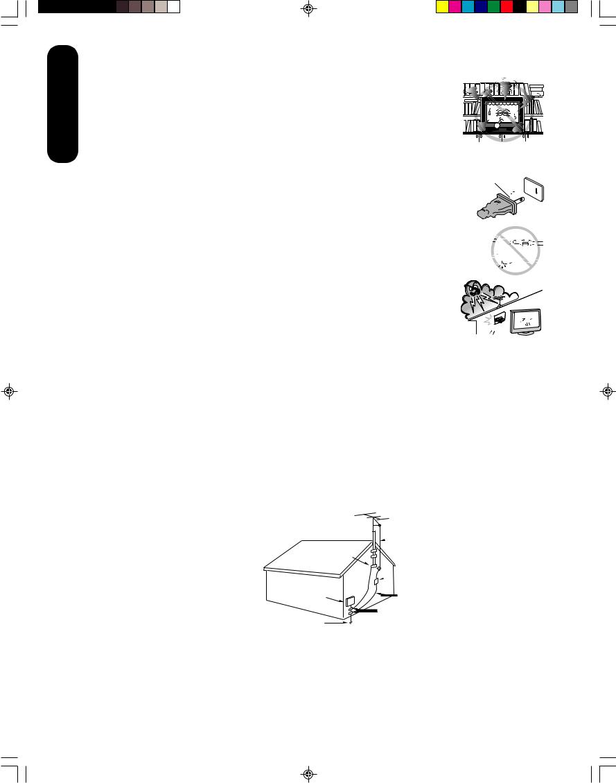
17.OUTDOOR ANTENNA GROUNDING
If an outside antenna or cable system is connected to the unit, be sure the antenna or cable system is grounded to provide some protection against voltage surges and built-up static charges, Section 810 of the National Electrical Code (NEC), ANSI/NFPA 70, provides information with respect to proper grounding of the mast and supporting structure, grounding of the lead-in wire to an antenna discharge unit, size of grounding conductors, location of antenna discharge unit, connection to grounding electrodes, and requirements for the grounding electrode.
EXAMPLE OF ANTENNA GROUNDING AS PER THE NATIONAL ELECTRICAL CODE
NEC-NATIONAL ELECTRICAL CODE
S2898A
 ANTENNA LEAD IN WIRE
GROUND
CLAMP
ANTENNA DISCHARGE UNIT
 (NEC SECTION 810-20)
ELECTRIC SERVICE
EQUIPMENT GROUNDING CONDUCTORS
 (NEC SECTION 810-21)
POWER SERVICE GROUNDING |
GROUND CLAMPS |
ELECTRODE SYSTEM (NEC ART 250, PART H) |
|
4
J3U70101C(E)P02-10 |
4 |
15/06/2005, 4:10 PM |
18.SERVICING
Do not attempt to service this unit yourself, as opening or removing covers may expose you to dangerous voltage or other hazards. Refer all servicing to qualified service personnel.
For example:
a.When the power-supply cord or plug is damaged.
b.If liquid has been spilled, or objects have fallen into the unit.
c.If the unit has been exposed to rain or water.
d.If the unit does not operate normally by following the operating instructions. Adjust only those 

 controls that are covered by the operating instructions, as an improper adjustment of other
controls may result in damage and will often require extensive work by a qualified technician to restore the unit to its normal operation.
e.If the unit has been dropped or the cabinet has been damaged.
f.When the unit exhibits a distinct change in performance, this indicates a need for service.
19.REPLACEMENT PARTS
When replacement parts are required, be sure the service technician uses replacement parts specified by the manufacturer or those that have the same characteristics as the original part.
Unauthorized substitutions may result in fire, electric shock or other hazards.
20.SAFETY CHECK
Upon completion of any service or repairs to this unit, ask the service technician to perform safety checks to determine that the unit is in proper operating condition.
21.HEAT
The product should be situated away from heat sources such as radiators, heat registers, stoves, or other products (including amplifiers) that produce heat.
22.CONNECTING
When you connect the product to other equipment, turn off the power and unplug all of the equipment from the wall outlet. Failure to do so may cause a product damage. Read the owner's manual of the other equipment carefully and follow the instructions when making any connections.
23.HEADPHONES
When you use headphones, keep the volume at a moderate level. Using headphones continuously at a high volume may cause hearing damage.
24.LCD
Do not press on or jolt the LCD panel. Doing so may cause the LCD panel glass to break and injury may occur. Should the LCD panel be broken and liquid leaks out, do not inhale or swallow it. Doing so may cause poisoning. If you have got it into your mouth, wash it out and consult your doctor. If your hands or clothes have touched it, wipe them with alcohol and a cleaning cloth and then wash them well.
Introduction
your Connecting
TV
up Setting TV your
ON DISPOSAL
This product contains mercury. Disposal of mercury may be regulated due to environmental considerations. For disposal or recycling information, please contact your local authorities or the Electronic Industrial Alliance: www.eiae.org.
5
the Using
Features TV’s
Appendix
J3U70101C(E)P02-10 |
5 |
15/06/2005, 4:10 PM |
Introduction
Important notes about your LCD TV
The following symptoms are technical limitations of LCD Display technology and are not an indication of malfunction; therefore, Toshiba is not responsible for perceived defects resulting from these symptoms.
1)An afterimage (ghost) may appear on the screen if a fixed, non-moving image is displayed for a long period of time. The afterimage is not permanent and will disappear in a short period of time.
2)The LCD panel contained in this TV is manufactured using an extremely high level of precision technology; however, there may be an occasional pixel (dot of light) that does not operate properly (does not light, remains constantly lit, etc.). This is a structural property of LCD technology, is not a sign of malfunction, and is not covered under your warranty. Such pixels are not visible when the picture is viewed from a normal viewing distance.
Note: Interactive video games that involve shooting a “gun” type of joystick at an on-screen target may not work with this TV.
Precautions
Notes on handling
■Do not subject the LCD panel to physical shock, such as dropping it. It may cause unit damage and malfunction.
■Retain the original shipping carton and packing materials. For maximum protection when shipping, repack the unit as it was originally packed at the factory.
■Do not use volatile liquids, such as insecticide, near the unit. Do not leave rubber or plastic products in contact with the unit for prolonged periods of time. Doing so will leave marks on the finish.
■The top and rear panels of the unit may become warm after a long period of use. This is not a malfunction.
■When the unit is not in use, turn off the power.
■If you do not use the unit for a long period, the unit may not function properly in the future. Turn on and use the unit occasionally.
Notes on locating the unit
■When you place this unit near a TV, radio, or VCR, the playback picture may become poor and the sound may be distorted. In this case, place the unit away from the TV, radio, or VCR.
■To avoid damage to this product, never place or store the TV in direct sunlight; hot, humid areas; or areas subject to excessive dust or vibration.
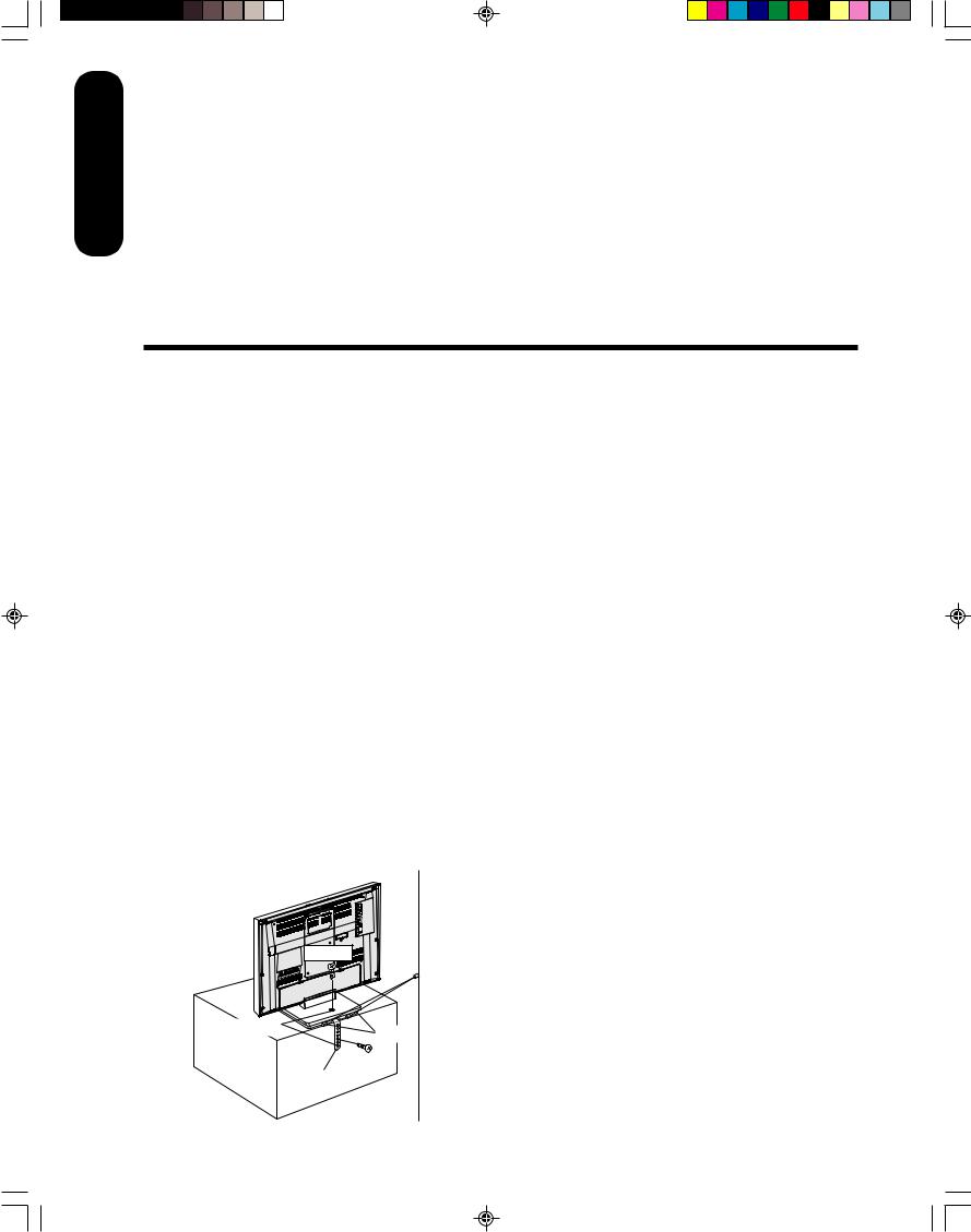
■Always place the TV on the floor or a sturdy, level stable surface that can support the weight of the unit. Use a sturdy tie between the TV's rear hooks and the rear wall, pillar, etc., or screw the TV to the stand using the TV’s rear screw hole or a safety band (see illustration).
Notes on cleaning
Clean only with a soft, dry, lint-free cloth.
Notes on LCD
■The color LCD is manufactured using extremely high precision technology, but even so may include certain pixels that do not operate properly (that do not light, that remain lit constantly, etc.). We do our best to keep the number of these defective pixels to a minimum, but please understand that they cannot be completely eliminated even with the most advanced manufacturing technologies available today.
■The fluorescent tube which illuminates the panel from the inside will deteriorate with use. When the LCD becomes dim, flickers, or does not illuminate, contact your dealer for replacement.
■The brightness of the LCD monitor differs slightly depending on the viewing angles. Adjust the angle to obtain the best viewing. (The recommended angle is 90 degrees to the monitor.)
Screw
Tie
Wall
Screw holes
Hooks
TV Stand |
Screw |
|
|
|
Safety Band |
6
J3U70101C(E)P02-10 |
6 |
15/06/2005, 4:10 PM |
Introduction ........................................................... |
2 |
FCC compliance information ...................................... |
3 |
IMPORTANT SAFEGUARDS ..................................... |
3 |
Precautions ................................................................ |
6 |
Exploring your new TV................................................ |
8 |
Selecting a location for the TV .................................... |
9 |
Connecting your TV .............................................. |
9 |
Connecting a VCR ...................................................... |
9 |
Connecting a cable converter box or antenna .......... |
10 |
Connecting a DVD player/satellite receiver and a |
|
VCR .......................................................................... |
11 |
Connecting a DVD player with ColorStream® |
|
(component video) and a VCR ................................. |
12 |
Connecting a DTV receiver/set-top box with |
|
ColorStream® (component video) and a VCR .......... |
13 |
Connecting a camcorder .......................................... |
14 |
Connecting an HDMI™ or a DVI device to the |
|
HDMI input ............................................................... |
15 |
Connecting a PC (Personal Computer) .................... |
16 |
Power source....................................................... |
16 |
Power connection ..................................................... |
16 |
Setting up your TV .............................................. |
17 |
Using the remote control .......................................... |
17 |
Preparing the remote control for use .................. |
17 |
Installing the remote control batteries ................. |
17 |
Using the remote control to operate your other |
|
devices ................................................................ |
17 |
Programming the remote control to operate your |
|
other devices ...................................................... |
18 |
Cable TV converter/satellite receiver, VCR and |
|
DVD player code tables ...................................... |
19 |
Learning about the remote control ...................... |
21 |
Starting setup ........................................................... |
22 |
Changing the on-screen display language ......... |
22 |
Adding channels to the TV’s memory ................. |
23 |
Programming channels automatically ................. |
23 |
Adding and erasing channels manually .............. |
23 |
Changing channels ............................................. |
23 |
Using the TV’s features ...................................... |
24 |
Adjusting the channel settings .................................. |
24 |
Switching between two channels ............................. |
24 |
Programming your favorite channels ........................ |
24 |
Using the LOCKS menu ........................................... |
25 |
Selecting a password .......................................... |
25 |
Using the V-Chip (parental control) feature ......... |
26 |
Locking channels ................................................ |
27 |
Locking the video inputs ..................................... |
27 |
Setting the GameTimerTM .................................... |
28 |
Using the panel lock feature ............................... |
28 |
Labeling channels .................................................... |
29 |
Selecting the video input source .............................. |
30 |
Labeling the video input sources .............................. |
30 |
Setting the clock ....................................................... |
30 |
Setting the ON timer ................................................. |
31 |
Viewing the wide-screen picture formats (480i and |
|
480p signals only) .................................................... |
32 |
Selecting the cinema mode ...................................... |
33 |
Using the ASPECT feature ....................................... |
33 |
Setting the sleep timer .............................................. |
34 |
Using the closed caption feature .............................. |
34 |
Adjusting the picture ................................................. |
35 |
Selecting the picture mode ................................. |
35 |
Adjusting the picture quality ................................ |
35 |
Using the CableClear® feature ............................ |
36 |
Selecting the color temperature .......................... |
36 |
Resetting your picture adjustments .................... |
36 |
Adjusting the sound .................................................. |
37 |
Muting the sound ................................................ |
37 |
Selecting stereo/SAP broadcasts ....................... |
37 |
Adjusting the sound quality ................................. |
37 |
Resetting your audio adjustments ...................... |
38 |
Using the StableSound® feature ......................... |
38 |
Using the WOW™ surround sound feature ........ |
38 |
Selecting the HDMI audio input source .............. |
39 |
Adjusting the back lighting feature ........................... |
39 |
Displaying on-screen information ............................. |
39 |
Auto power off .......................................................... |
39 |
Understanding the Power Return feature ................. |
39 |
Picture/Audio adjustments in the PC mode .............. |
40 |
Resetting your picture/audio adjustment |
|
in the PC mode ......................................................... |
40 |
Appendix .............................................................. |
41 |
Troubleshooting ........................................................ |
41 |
Specifications ........................................................... |
42 |
Limited United States Warranty ................................ |
43 |
Limited Canada Warranty ......................................... |
44 |
7
Introduction
your Connecting
TV
up Setting TV your
the Using
Features TV’s
Appendix
J3U70101C(E)P02-10 |
7 |
15/06/2005, 4:10 PM |
Introduction
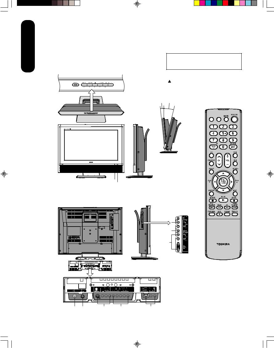
Exploring your new TV
You can operate your TV by using the buttons on the top panel or the remote control. The side and back panels provide the inputs to connect other equipment to your TV.
Top panel
|
|
|
|
|
|
|
|
|
|
|
|
4 |
- |
3 |
/ |
||||||||||
|
||||||||||||
+/ |
|
|
|
|||||||||
POWERMENU VOLUMECHANNEL SELECT |
||||||||||||
|
|
|
|
|
|
|
|
|
|
|
INPUT |
|
|
|
|
|
|
|
|
|
|
|
|
|
|
|
|
|
|
|
|
|
|
|
|
|
|
|
|
|
|
|
|
|
|
|
|
|
|
|
|
The STARTING SETUP feature appears the first time you turn on the TV. See page 22 for details.
The volume and channel buttons on the top panel can be used as / and
and  /
/ buttons while the TV menu is displayed on screen.
Approx 5° Approx 10°
Remote control
Top
INPUT DISPLAY
Right side
Front
|
|
You can adjust |
|
|
the angle of the |
|
|
TV screen 5° |
|
|
forward or 10° |
|
|
backward from |
|
Power indicator |
vertical. Hold the |
|
base of the TV |
|
|
Remote sensor |
|
|
while adjusting |
|
|
|
|
|
|
the angle. |
|
|
Left side |
Back |
|
Side panel |
HEADPHONE 
VIDEO-2 IN 
PC IN
CT-885
Back panel
DC IN RF IN VIDEO-1 IN ColorStream HDMI IN
HD IN
8
J3U70101C(E)P02-10 |
8 |
15/06/2005, 4:10 PM |
Selecting a location for the TV
•Place the TV on the floor or on a sturdy platform in a location where light does not directly hit the screen.
•Place the TV far enough from the walls to allow proper ventilation. Inadequate ventilation may cause overheating, which may damage the TV.
Connecting your TV
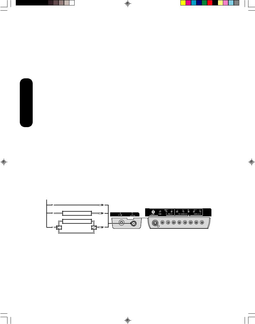
If you haven’t connected electronic equipment before, or you have been frustrated in the past, you may wish to read this section. (Cables are not supplied.)
•A coaxial cable is the standard cable that comes in from your antenna or cable converter box. Coaxial cables use “F” connectors.
•Standard A/V (audio/video) cables are usually color coded according to use: yellow for video and red and white for audio. The red audio cable is for the stereo right channel, and the white audio cable is for the stereo left (or mono) channel. If you look at the rear panel of the TV, you will see that the terminals are color coded in the same manner as the cables.
•S-video cables provide better picture performance than standard video cables. S-video cables can only be used with S-video compatible components.
•Component video cables provide better picture performance than S-video cables. Component video cables can only be used with component video compatible components.
•HDMI (High Definition Multimedia Interface) cable is for use with video equipment that has HDMI output (see page 15).
S-Video
ANTENNA Cable
Coaxial Cable
AUDIO
Cables
Component video
Cables
VIDEO
Cable
HDMI
Cable
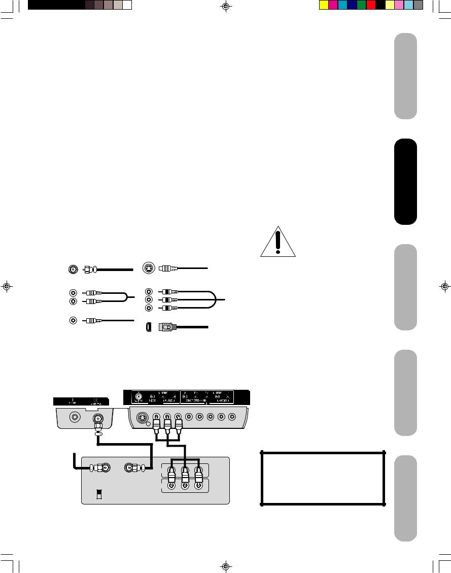
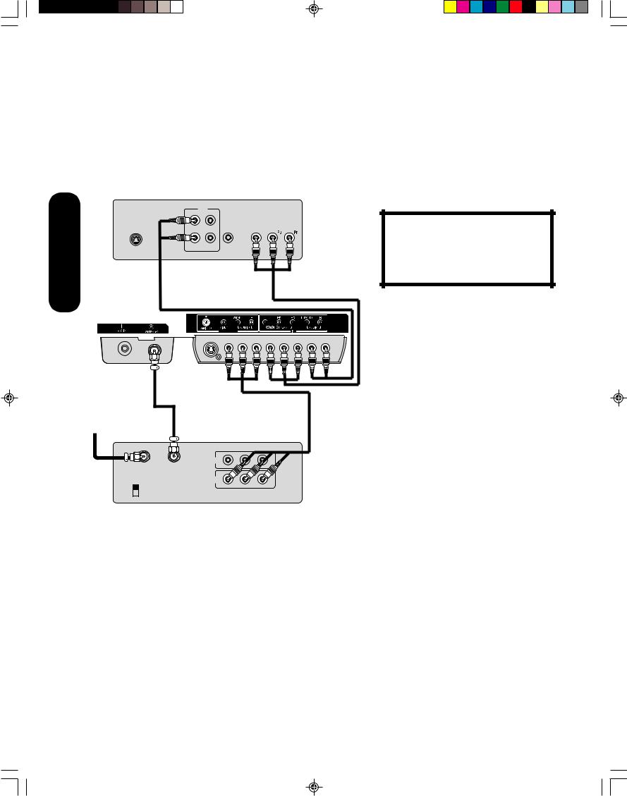
Connecting a VCR
This connection allows you to watch local channels and video programs, play or record on the VCR while watching TV, and record from one channel while watching another channel.
TV back panel
VIDEO-1 IN
Cable Lead-in from cable box or antenna
|
|
Stereo VCR |
|
|
IN |
|
|
IN from ANT |
OUT to TV |
|
|
|
OUT |
|
|
CH 3 |
L |
R |
|
CH 4 |
|||
VIDEO |
AUDIO |
||
|
9
Note:
To prevent equipment damage, do not plug in any power cords until you have finished connecting all equipment.
You will need:
•two coaxial cables
•one set of standard A/V cables
Note:
If using a mono VCR, connect L/Mono to VCR Audio OUT using only one audio cable. For better picture quality, if your VCR has S-video, you can use an S-video cable instead of the standard video cable. Do not connect a standard video cable and an S-video cable to VIDEO-1 simultaneously.
The unauthorized recording, use, distribution or revision of television programs, videotapes, DVDs, and other materials is prohibited under the Copyright Laws of the United States and other countries, and may subject you to civil and criminal liability.
Introduction
your Connecting
TV
up Setting TV your
the Using
Features TV’s
Appendix
J3U70101C(E)P02-10 |
9 |
15/06/2005, 4:10 PM |
Connecting your TV
Connecting a cable converter box or antenna
This television has an extended tuning range and can tune most cable channels without using a cable company supplied converter box. Some cable companies offer "premium pay channels" in which the signal is scrambled. Descrambling these signals for normal viewing requires the use of a descrambler device, which is generally provided by the cable company.
Option 1: For Subscribers to Basic Cable TV Service
For basic cable service not requiring a Converter/Descrambler box, connect the incoming 75 ohm Coaxial Cable directly to the Antenna Jack on the back of the television.
Option 2: For Subscribers to Scrambled Cable TV Service
If you subscribe to a cable service that requires the use of a Converter/ Descrambler box, connect the incoming cable to the Converter/ Descrambler box and connect the output of the box to the Antenna Jack on the back of the television. Follow the connections shown below. Set the television to the output of the Converter/Descrambler box (usually channel 3 or 4) and use the Converter/Descrambler box to select channels.
Option 3: For Subscribers to Unscrambled Basic Cable with Scrambled Premium Channels
If you subscribe to a cable service in which basic cable channels are unscrambled and premium channels require the use of a Converter/ Descrambler box, you may wish to use a two-set signal splitter (sometimes called a "two-set coupler") and an A/B Switch box from the cable installer or an electronics supply store. Follow the connections shown below. With the switch in the "B" position, you can directly tune any nonscrambled channels on your TV. With the switch in the "A" position, tune your TV to the output of the Converter/Descrambler box (usually channel 3 or 4) and use the box to tune scrambled channels.
From Cable |
|
Option 1: |
|
Option 2: |
|
|
Cable Box |
Option 3: |
Cable Box |
|
|
Splitter |
A / B Switch A B |
Note:
When you use a converter box with your TV, there may be features that you cannot program using the remote control, such as labeling channels, blocking channels, and programming your favorite channels.
TV back panel
VIDEO-1 IN
10
J3U70101C(E)P02-10 |
10 |
15/06/2005, 4:10 PM |
Connecting a DVD player/satellite receiver and a VCR
This connection allows you to watch DVD/satellite, VCR, or TV programs. You can record from the satellite receiver and TV, as well as record one TV channel while watching another channel.
From satellite
DVD player / Satellite Receiver
VIDEO AUDIO
L R
Satellite IN OUT to TV |
OUT |
S-VIDEO
Stereo VCR |
IN
IN from ANT OUT to TV
|
OUT |
|
|
CH 3 |
L |
R |
|
CH 4 |
|||
VIDEO |
AUDIO |
||
|
TV back panel
VIDEO-1 IN
You will need:
•three coaxial cables
•two sets of standard A/V cables
•one S-video cable
Note:
You can use a standard video cable instead of the S-video cable, but the picture quality will decrease. If you use an S-video cable between the TV and DVD player/satellite receiver, make the audio connections but remove the standard video cable. Do not connect both an S-video and a standard video cable to VIDEO1 at the same time or the picture performance will be unacceptable.
The unauthorized recording, use, distribution or revision of television programs, videotapes, DVDs, and other materials is prohibited under the Copyright Laws of the United States and other countries, and may subject you to civil and criminal liability.
Introduction
your Connecting
TV
up Setting TV your
the Using
Features TV’s
Appendix
11
J3U70101C(E)P11-16 |
11 |
15/06/2005, 4:10 PM |
Connecting your TV
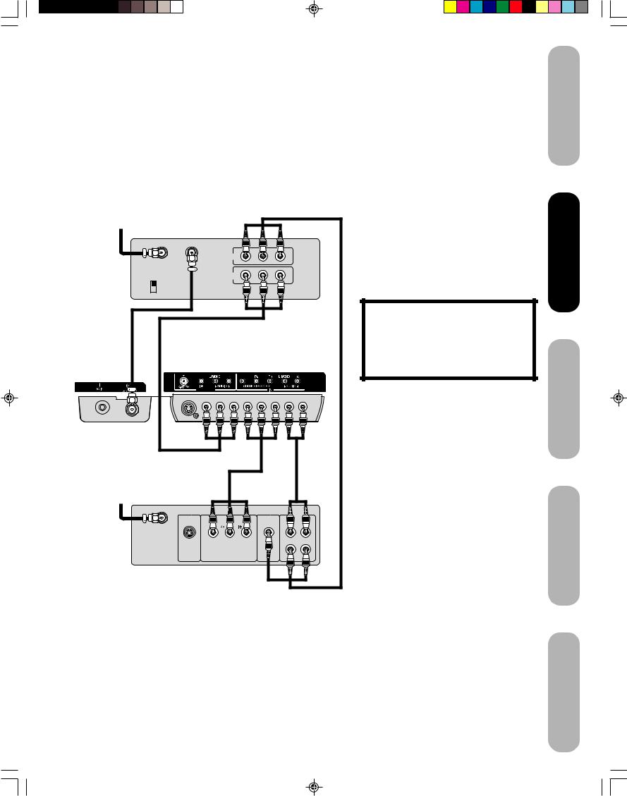
Connecting a DVD player with ColorStream® (component video) and a VCR
This connection allows you to watch DVD, VCR, or TV programs and record TV programs. You can record from one source while watching a program from another source. Your TV is capable of using ColorStream (component video). Connecting your TV to a component video compatible DVD player, such as a Toshiba DVD player with ColorStream®, can greatly enhance picture quality and performance.
DVD player with Component video
OUT
L
COMPONENT VIDEO
R Y
AUDIO |
VIDEO |
S-VIDEO |
OUT |
TV back panel
VIDEO-1 IN
From antenna
Stereo VCR
|
IN |
|
|
IN from ANT |
OUT to TV |
|
|
|
OUT |
|
|
CH 3 |
L |
R |
|
CH 4 |
|||
VIDEO |
AUDIO |
||
|
You will need:
•two coaxial cables
•one set of standard A/V cables
•one set of component video cables
•one pair of standard audio cables
Note:
The ColorStream HD jacks can be used with Progressive (480p, 720p) and Interlaced (480i, 1080i) scan systems. A 1080i signal will provide the best picture performance.
The unauthorized recording, use, distribution or revision of television programs, videotapes, DVDs, and other materials is prohibited under the Copyright Laws of the United States and other countries, and may subject you to civil and criminal liability.
12
J3U70101C(E)P11-16 |
12 |
15/06/2005, 4:10 PM |
Connecting a DTV receiver/set-top box with ColorStream® (component video) and a VCR
This connection allows you to watch DTV (digital TV), VCR, and TV programs, and record DTV and TV programs.
Your TV has ColorStream® (component video) inputs. Connecting your TV to a DTV receiver with component video can greatly enhance picture quality and realism.
From Antenna
Stereo VCR |
|
|
|
|
|
|
IN |
|
|
IN from ANT |
OUT to TV |
|
|
|
|
|
OUT |
|
|
CH 3 |
|
|
L |
R |
CH 4 |
|
|
||
|
VIDEO |
AUDIO |
|
|
|
|
|
||
|
|
|
TV back panel |
|
|
VIDEO-1 IN |
|
|
|
From DTV |
|
|
|
|
Antenna |
|
|
|
|
|
|
|
|
AUDIO |
|
|
|
|
OUT |
|
Y |
|
|
L |
|
S-VIDEO |
COMPONENT VIDEO |
VIDEO |
R |
|
|
|
OUT |
|
DTV Receiver |
|
|
|
|
with Component video |
|
|
|
|
You will need:
•three coaxial cables
•two sets of standard A/V cables
•one set of standard audio cables
•one set of component video cables
Note:
For HDMI connection, see page 15.
The ColorStream HD jacks and HDMI jacks can be used with Progressive (480p, 720p) and Interlaced (480i, 1080i) scan systems. If your DTV receiver does not have component video, use the S-video and standard audio connections instead. Do not connect
both an S-video and a standard video cable to VIDEO1 at the same time or the picture performance will be unacceptable.
The unauthorized recording, use, distribution, or revision of television programs, videotapes, DVDs, and other materials is prohibited under the Copyright Laws of the United States and other countries, and may subject you to civil and criminal liability.
Introduction
your Connecting
TV
up Setting TV your
the Using s’TV
Features
Appendix
13
J3U70101C(E)P11-16 |
13 |
15/06/2005, 4:10 PM |

Connecting your TV
Connecting a camcorder
This connection allows you to watch videos recorded on a camcorder.
VHS Camcorder
S-VIDEO |
VIDEO AUDIO |
|
L |
R
OUT
TV side panel
S-VHS Camcorder
S-VIDEO |
VIDEO |
AUDIO |
|
|
L |
|
|
R |
OUT |
|
|
Rear lower left of TV |
||
VIDEO-1 IN |
|
|
You will need:
• one set of standard AV cables
You will need:
•one S-video cable
•one pair of standard audio cables
Note:
For better picture quality, if your camcorder has S-video, you can use an S-video cable (plus the standard audio cables) instead of a standard video cable.
Do not connect both a standard video cable and an S-video cable at the same time, or the picture performance will be unacceptable.
14
J3U70101C(E)P11-16 |
14 |
15/06/2005, 4:10 PM |
Connecting an HDMI™ or a DVI device to the HDMI input
The HDMI[1] input on your TV receives digital audio and uncompressed digital video from an HDMI device or uncompressed digital video from a DVI[2] device.
This input is designed to accept HDCP[3] program material in digital form from EIA/CEA-861/861B–compliant[4] consumer electronic devices (such as a set-top box or DVD player with HDMI or DVI output).
The HDMI input is designed for best performance with high definition video signals. It will accept and display 480i, 480p, 720p and 1080i signals.
Note: The HDMI jack is not intended for connection to and should not be used with a personal computer. For PC connection, see page 16.
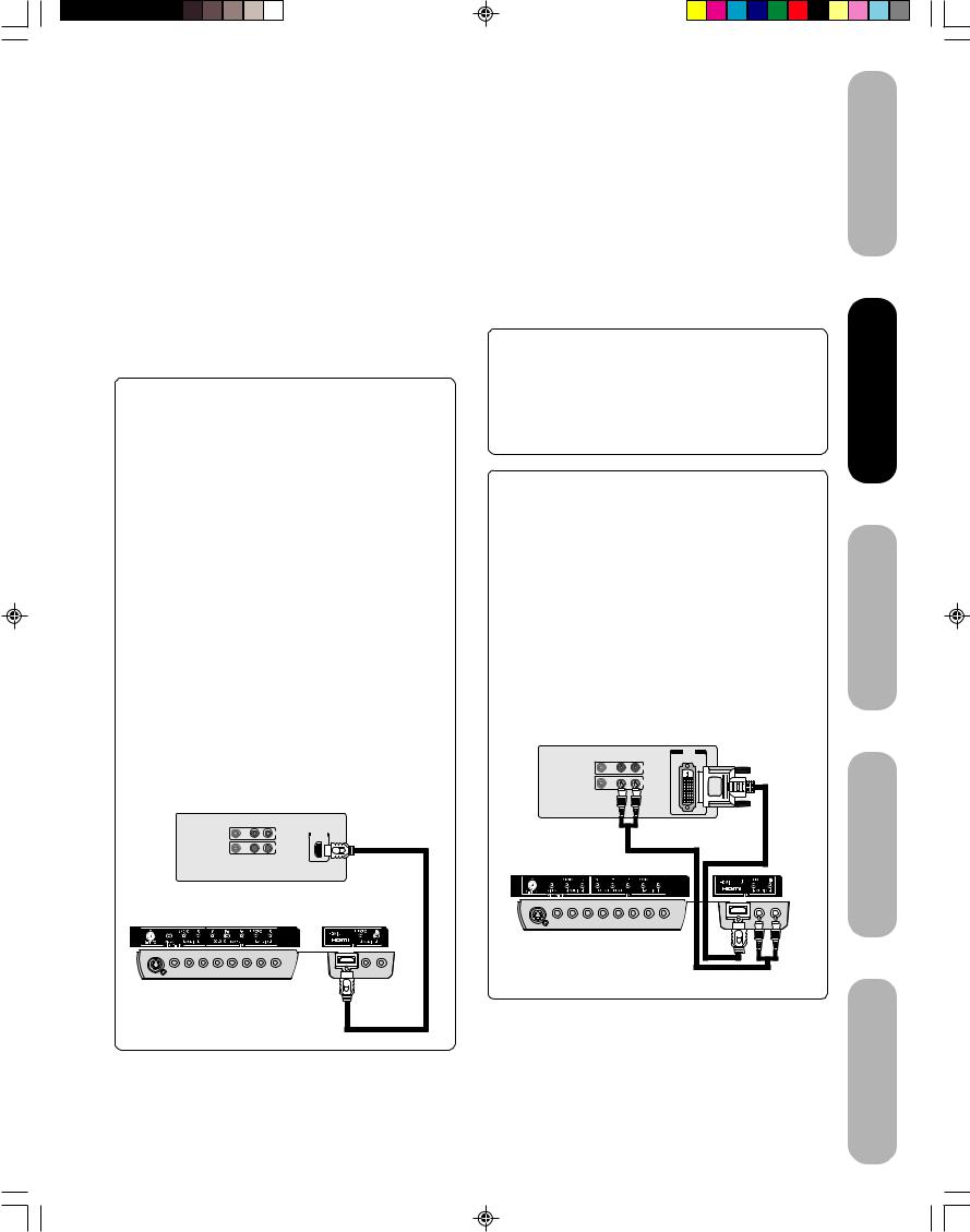
To connect an HDMI device, you will need:
•one HDMI cable (type A connector)
For proper operation, it is recommended that you use as short an HDMI cable as possible. You should not encounter difficulty if you use an HDMI cable that is shorter than 16.4 ft (5m).
HDMI cable transfers both video and audio. Separate analog audio cables are not required (see illustration below).
You must set the HDMI audio input setting to “HDMI” in the AUDIO menu (see page 39).
Some CDVs (Video CDs) may not output digital audio signals. In that case, you may hear sound by connecting analog audio cables. If you do use analog audio cables for this reason, you will need to set the HDMI audio input setting to “DVI” to hear the analog audio (see page 39). Note: If you connect an HDMI device and analog audio cables and play media with digital audio output, to hear digital audio you must set the HDMI audio input setting to “HDMI” (page 39).
HDMI device
VIDEO AUDIO
L R
HDMI
IN
OUT

 OUT
OUT
TV back panel
[1]HDMI = High-Definition Multimedia Interface.
[2]DVI = Digital Video Interface.
[3]HDCP = High-bandwidth Digital Content Protection.
[4]EIA/CEA-861/861B compliance covers the transmission of uncompressed digital video with highbandwidth digital content protection, which is being standardized for reception of high-definition video signals.
Because this is an evolving technology, it is possible that some devices may not operate properly with the TV.
To ensure that the HDMI or DVI device is reset properly, it is recommended that you follow these procedures:
•When turning on your electronic components, turn on the TV first, and then the HDMI or DVI device.
•When turning off your electronic components, turn off the HDMI or DVI device first, and then the TV.
To connect a DVI device, you will need:
•one HDMI–to–DVI adapter cable (HDMI type A connector)
For proper operation, the length of an HDMI-to-DVI adapter cable should not exceed 9.8 ft (3m). The recommended length is 6.6 ft (2m).
•one pair of standard analog audio cables
An HDMI-to-DVI adapter cable transfers only video. Separate analog audio cables are required (see illustration below).
You must set the HDMI audio input setting to “DVI” in the AUDIO menu (see page 39).
DVI device |
|
|
|
|
VIDEO |
AUDIO |
DVI |
||
OUT |
||||
|
L |
R |
||
|
|
|
IN |
|
|
|
|
OUT |
|
TV back panel |
|
|
|
|
Introduction
your Connecting
TV
up Setting TV your
the Using s’TV
Features
HDMI, the HDMI logo, and High-Definition Multimedia Interface are trademarks or registered trademarks of HDMI Licensing, LLC.
15
Appendix
J3U70101C(E)P11-16 |
15 |
15/06/2005, 4:10 PM |
 Loading...