


FILE NO. 060-200315
SERVICE MANUAL
Color Television
S3ES Chassis
21SZ2E, 21SZ2ES 21SZ2T, 21SZ2M 21SZ2MJ
Feb., 2004

SPECIFIC INFORMATIONS GENERAL ADJUSTMENTS
TABLE OF CONTENTS |
|
CHAPTER 1 GENERAL ADJUSTMENTS |
|
SAFETY INSTRUCTIONS ........................................................................................................................................ |
3 |
SET-UP ADJUSTMENT ............................................................................................................................................ |
4 |
SERVICE MODE ...................................................................................................................................................... |
6 |
DESIGN MODE ........................................................................................................................................................ |
9 |
ELECTRICAL ADJUSTMENTS .............................................................................................................................. |
10 |
CIRCUIT CHECK .................................................................................................................................................... |
12 |
CHAPTER 2 SPECIFIC INFORMATIONS |
|
SETTING & ADJUSTING DATA .............................................................................................................................. |
13 |
LOCATION OF CONTROLS ................................................................................................................................... |
14 |
PROGRAMMING CHANNEL MEMORY ................................................................................................................. |
15 |
CHASSIS AND CABINET REPLACEMENT PARTS LIST ...................................................................................... |
17 |
PC BOARDS BOTTOM VIEW................................................................................................................................. |
25 |
TERMINAL VIEW OF TRANSISTORS ................................................................................................................... |
29 |
CIRCUIT BLOCK DIAGRAM .................................................................................................................................. |
32 |
SPECIFICATIONS .............................................................................................................................................. |
END |
APPENDIX: |
|
CIRCUIT DIAGRAM |
|
– 2 –

CHAPTER 1 GENERAL ADJUSTMENTS
SAFETY INSTRUCTIONS
WARNING: BEFORE SERVICING THIS CHASSIS, READ THE “X-RAY RADIATION PRECAUTION”, “SAFETY PRECAUTION” AND “PRODUCT SAFETY NOTICE” INSTRUCTIONS BELOW.
X-RAY RADIATION PRECAUTION
1.Excessive high voltage can produce potentially hazardous X-RAY RADIATION. To avoid such hazards, the high voltage must not be above the specified limit. The nominal value of the high voltage of this receiver is (A) kV at zero beam current (minimum brightness) under a (C) V AC power source. The high voltage must not, under any circumstances, exceed (B) kV.
Refer to table-1 for high voltage (A), (B) & AC voltage (C). (See SETTING & ADJUSTING DATA on page 13)
Each time a receiver requires servicing, the high voltage should be checked following the HIGH VOLTAGE CHECK procedure in this manual. It is recommended that the reading of the high voltage be recorded as a part of the service record. It is important to use an accurate and reliable high voltage meter.
2.The only source of X-RAY RADIATION in this TV receiver is the picture tube. For continued X-RAY RADIATION protection, the replacement tube must be exactly the same type tube as specified in the parts list.
3.Some part in this receiver have special safety-related characteristics for X-RAY RADIATION protection. For continued safety, parts replacement should be undertaken only after referring to the PRODUCT SAFETY NOTICE below.
SAFETY PRECAUTION
WARNING : Service should not be attempted by anyone unfamiliar with the necessary precautions on this receiver. The following are the necessary precautions to be observed before servicing this chassis.
1.An isolation transformer should be connected in the power line between the receiver and the AC line before any service is performed on the receiver.
2.Always discharge the picture tube anode to the CRT conductive coating before handling the picture tube. The picture tube is highly evacuated and if broken, glass fragments will be violently expelled. Use shatter proof goggles and keep picture tube away from the unprotected body while handling.
3.When replacing a chassis in the cabinet, always be certain that all the protective devices are put back in place, such as; nonmetallic control knobs, insulating covers, shields, isolation resistor-capacitor network etc.
PRODUCT SAFETY NOTICE
Many electrical and mechanical parts in this chassis have special safety-related characteristics. These characteristics are often passed unnoticed by a visual inspection and the protection afforded by them cannot necessarily be obtained by using replacement components rated for higher voltage, wattage, etc. Replacement parts which have these special safety characteristics are identified in this manual and its supplements; electrical components having such features are identified by the international hazard symbols on the schematic diagram and the parts list.
Before replacing any of these components, read the parts list in this manual carefully. The use of substitute replacement parts which do not have the same safety characteristics as specified in the parts list may create shock, fire, X-ray radiation or other hazards.
SPECIFIC INFORMATIONS GENERAL ADJUSTMENTS
– 3 –

SPECIFIC INFORMATIONS GENERAL ADJUSTMENTS
WARNING: BEFORE SERVICING THIS CHASSIS, READ THE “X-RAY RADIATION PRECAUTION”, “SAFETY PRECAUTION” AND “PRODUCT SAFETY NOTICE” ON PAGE 3 OF THIS MANUAL.
SET-UP ADJUSTMENT
■The following adjustments should be made when a complete realignment is required or a new picture tube is installed. Perform the adjustments in order as follows :
1.Color Purity
2.Convergence
3.White Balance
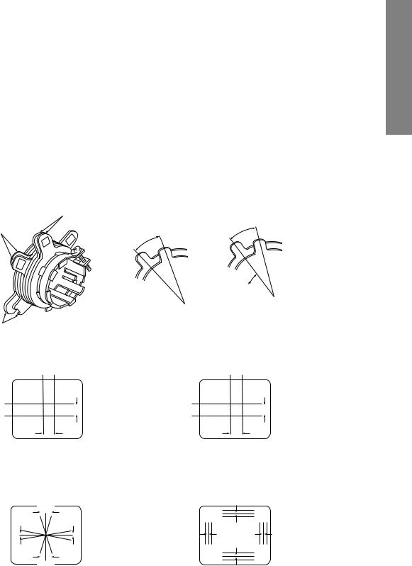
Note: The PURITY/CONVERGENCE MAGNET assembly and rubber wedges need mechanical positioning. Refer to figure 1.
Mounting position of the purity magnet assembly should fit to same position as old one because slightly difference to the position depend on a kind of tube.
* There are no adjustment of purity and convergence in some picture tube (Unified with purity magnet)
COLOR PURITY ADJUSTMENT
NOTE : Before attempting any purity adjustments, the receiver should be operated for at least fifteen minutes.
1.Demagnetize the picture tube and cabinet using a degaussing coil.
2.Set the brightness and contrast to maximum.
3.Use a green raster from among the built-in test signals.
4.Loosen the clamp screw holding the yoke and slide the yoke backward or forward to provide vertical green belt (zone) in the picture screen.
DEFLECTION
YOKE
29.1mm(28", 29") 25mm(25") 19mm(19", 20", 21") 14mm(13", 14")
PURITY/
CONVERGENCE
MAGNET ASS'Y
GLASS CLOTH
TAPES
5.Remove the Rubber Wedges.
6.Rotate and spread the tabs of the purity magnet (See figure 2.) around the neck of the picture tube until the green belt is in the center of the screen. At the same time, enter the raster vertically.
7.Slowly move the yoke forward or backward until a uniform green screen is obtained. Tighten the clamp screw of the yoke temporarily.
8.Check the purity of the red and blue raster.
TEMPORARY
MOUNTING
RUBBER WEDGE
ADHESIVE
DEFLECTION
YOKE
Figure 1.
– 4 –
CONVERGENCE ADJUSTMENTS
NOTE: Before attempting any convergence adjustments, the receiver should be operated for at least fifteen minutes.
■CENTER CONVERGENCE ADJUSTMENT
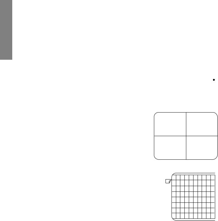
1.Use the cross-dot pattern from among the built-in test signals.
2.Set the brightness and contrast for well defined pattern.
3.Adjust two tabs of the 4-Pole Magnets to change the angle between them (See figure 2.) and superimpose red and blue vertical lines in the center area of the picture screen.
4.Turn the both tabs at the same time keeping the angle constant to superimpose red and blue horizontal lines at the center of the screen.
5.Adjust two tabs of 6-Pole Magnets to superimpose red/ blue line and green one. Adjusting the angle affects the vertical lines and rotating both magnets affects the horizontal lines.
6.Repeat adjustments 3, 4, 5 keeping in mind red, green and blue movement, because 4-Pole Magnets and 6-Pole Magnets have mutual interaction and make dot movement complex.
■CIRCUMFERENCE CONVERGENCE ADJUSTMENT
1.Loosen the clamping screw of deflection yoke slightly to allow the yoke to tilt.
2.Temporarily put a wedge as shown in figure 1. (Do not remove cover paper on adhesive part of the wedge.)
3.Tilt front of the deflection yoke up or down to obtain better convergence in circumference. (See figure 3.) Push the mounted wedge into the space between picture tube and the yoke to fix the yoke temporarily.
4.Put other wedge into bottom space and remove the cover paper to stick.
5.Tilt front of the yoke right or left to obtain better convergence in circumference. (See figure 3.)
6.Keep the yoke position and put another wedge in either upper space. Remove cover paper and stick the wedge on picture tube to fix the yoke.
7.Detach the temporarily mounted wedge and put it in another upper space. Stick it on picture tube to fix the yoke.
8.After fixing three wedges, recheck overall convergence. Tighten the screw firmly to fix the yoke and check the yoke is firm.
9.Stick three adhesive tapes on wedges as shown in figure 1.
6-POLE MAGNETS
4-POLE |
ADJUST THE ANGLE |
FIXED |
|
MAGNETS |
(VERTICAL LINES) |
||
|
|
|
ROTATE TWO TABS |
|
|
|
AT THE SAME TIME |
|
|
|
(HORIZONTAL LINES) |
|
PURITY |
|
|
|
MAGNETS |
|
|
|
CONVERGENCE MAGNET ASSEMBLY |
ADJUSTMENT OF MAGNETS |
||
|
Figure |
2. |
|
BLU |
RED |
RED/BLU GRN |
|
BLU |
|
RED/BLU |
|
RED |
|
GRN |
|
4-POLE MAGNETS MOVEMENT |
6-POLE MAGNETS MOVEMENT |
||
|
Center Convergence by Convergence Magnets |
|
|
BGR |
B |
|
|
|
|
|
|
|
|
G |
RGB |
|
|
R |
|
R |
B |
|
|
G |
G |
|
|
B |
R |
BGR |
|
|
|
R |
|
|
|
|
|
|
|
|
G |
RGB |
|
B |
|
|
|
||
INCLINE THE YOKE UP (OR DOWN) |
INCLINE THE YOKE RIGHT (OR LEFT) |
||
Circumference Convergence by DEF Yoke
Figure 3. Dot Movement Pattern
SPECIFIC INFORMATIONS GENERAL ADJUSTMENTS
– 5 –

SPECIFIC INFORMATIONS GENERAL ADJUSTMENTS
SERVICE MODE
1. ENTERING TO SERVICE MODE |
|
|
|
|
|
|
|
|
|
|
|||
1) Press o button once on |
2) Press o button again to |
3) While pressing the o button, |
|||||||||||
Remote Control. |
|
keep pressing. |
press MENU button on TV set. |
||||||||||
|
|
|
|
|
|
|
|
|
|
|
|
|
|
|
|
|
|
|
|
|
|
|
|
|
|
S |
|
|
|
|
|
|
|
|
|
|
|
|
Item |
|
|
|
|
|
|
|
|
|
|
|
|
|
|
|
|
|
|
|
|
|
|
|
|
|
|
|
Data |
|
|
|
|
|
|
|
|
|
|
|
|
|
|
|
|
|
|
|
|
|
|
|
|
|
|
|
|
|
|
|
|
|
|
|
|
|
|
|
(Service mode display) |
||||
2.DISPLAYING THE ADJUSTMENT MENU
1)Press MENU button on TV.
Service mode |
|
|
|
|
|
|
Adjustment mode |
||||
|
|
|
Press |
|
|
|
|
|
|
Item |
|
|
|
|
|
|
|
|
|
||||
|
|
|
|
|
|
|
|
||||
S |
|
|
|
|
|
|
|
Data |
|||
|
|
|
Press |
|
|
|
|
|
|
||
|
|
|
|
|
|
|
|
|
|
|
|
3.KEY FUNCTION IN THE SERVICE MODE
The following key entry during display of adjustment menu provides special functions.
A single horizontal line ON/OFF: |
- / - - button (on Remote) or a button (on TV) |
||||||||||
Test signal selection : |
a button (on Remote) |
||||||||||
Selection of the adjustment items : |
Channel s/t (on TV or Remote) |
||||||||||
Change of the data value : |
Volume ; +/– (on TV or Remote) |
||||||||||
Adjustment menu mode ON/OFF : |
MENU button (on TV) |
||||||||||
Initialization of the memory (QA02) : |
CALL + Channel button on TV (s) |
||||||||||
Reset the count of operating protect |
|
|
|
|
|
|
|
|
|
|
|
circuit to “00”: |
CALL + Channel button on TV (t) |
||||||||||
“RCUT” selection : |
1 button |
|
|
|
|
|
|
|
|
|
|
“GCUT” selection : |
2 button |
|
|
|
|
|
|
|
|
|
|
“BCUT” selection : |
3 button |
|
|
|
|
|
|
|
|
|
|
“CNTX” (or “SCNT”) selection : |
4 button |
|
|
|
|
|
|
|
|
|
|
“COLC” selection : |
5 button |
|
|
|
|
|
|
|
|
|
Color thickness correction |
|
|
|
|
|
|||||||
“TNTC” selection : |
6 button |
|
|
|
|
|
|
|
|
|
note: Displayed differently as shown below, de- |
Test audio signal ON/OFF (1kHz) : |
8 button |
|
|
|
|
|
|
|
|
|
pending on the setting of the receiving color |
Self diagnostic display ON/OFF : |
9 button |
|
|
|
|
|
|
|
|
|
system. |
|
|
|
|
|
|
|
|
|
|
|
COLP (PAL) |
COLC (NTSC)
COLS (SECAM)
CAUTION : Never try to perform initialization unless you have changed the memory IC.
– 6 –

4.SELECTING THE ADJUSTING ITEMS
1)Every pressing of CHANNEL s button in the service mode changes the adjustment items in the order of table-2. (t button for reverse order)
Refer to table-2 for preset data of adjustment mode. (See SETTING & ADJUSTING DATA on page 13)
5.ADJUSTING THE DATA
1)Pressing of VOLUME ; +/– button will change the value of data in the range from 00H to FFH. The variable range depends on the adjusting item.
6.EXIT FROM SERVICE MODE
1)Pressing POWER button to turn off the TV once.
■INITIALIZATION OF MEMORY DATA OF QA02
After replacing QA02, the following initialization is required.
1.Enter the service mode, then select any register item.
2.Press and hold the CALL button on the Remote, then press the CHANNEL s button on the TV. The initialization of QA02 has been complated.
3.Check the picture carefully. If necessary, adjust any adjustment item above. Perform “Auto search Memory” on the owner’s manual.
CAUTION: Never attempt to initialize the data unless QA02 has been replaced.
7.TEST SIGNAL SELECTION
1)Every pressing of a button on the Remote Control changes the built-in test patterns on screen as described below in SERVICE MODE.
Signal off |
|
NTSC signals (14 patterns) |
|
|||||
|
|
|||||||
|
|
|
PAL signals (14 patterns) |
|
|
Signals |
Picture |
|
|
|
|
|
|
||||
|
|
|
|
|
|
|
||
|
|
|
|
|
|
|||
|
|
|
|
|
||||
• Red raster
• Green raster
• Blue raster
• All Black
• All White
• Black & White
• Black cross-bar
• White cross-bar
• Black cross-bar on green raster
• Black cross-hatch
• White cross-hatch
• Black cross-dot
• White cross-dot
• H signal (white)
• H signal (black)
* The signals marked with  are not usable to display in the Test signal for some model.
SPECIFIC INFORMATIONS GENERAL ADJUSTMENTS
– 7 –

SPECIFIC INFORMATIONS GENERAL ADJUSTMENTS
8.SELF DIAGNOSTIC FUNCTION
1)Press “9” button on Remote Control during display of adjustment menu in the service mode. The diagnosis will begin to check if interface among IC’s are executed properly.
2)During diagnosis, the following displays are shown.
<SELF CHECK>
23******
POWER : 00
BUS LINE : OK
BUS CONT : OK
BLOCK |
: |
UV V1 V2 |
|
|
QV01 |
|
|
|
Indicated color of mode now selected : Green and Red Indicated color of other modes : White
Green : Normal
Red : The microcomputer operates to provide judgement of no video signal. The red color is still indicated though the signal is input, failure may exist in input signal line including QV01.
QV01 : In case of indication green ---Normal
In case of indication red with input signal----
Failure may exist in output line including QV01.
Part number of microcomputer (QA01)
Operation number of protecting circuit ----“00” is normal.
When indication is other than “00”, overcurrent apts to flow, and circuit parts may possibly be damaged.
BUS LINE CHECK ----“OK” is normal.
“SDA1-GND” |
------------- SDA-GND short circuit. |
“SCL1-GND” -------------- |
SCL-GND short circuit. |
“SCL1-SDA1” ------------- |
SCL-SDA short circuit. |
BUS CONT ---- |
“ OK ” is normal. |
When indication shows “Q uuu NG”, the device with the number may possibly be damaged.
BLOCK
UV : TV reception mode
V1 : VIDEO 1 input mode (a1)
V2 : VIDEO 2 input mode (a2)
NOTE: Component which controls character display on screen is QT01 (TELETEXT IC.). If this display function fails to operate due to damage in QT01, self diagnosis procedure is as follows.
(1)In case that power indicator is blinking with interval of 0.5 seconds; it means protecting circuit (Current limiter) is operating, and circuit components may possibly be damaged. Check related components.
(2)In case that power indicator is blinking with interval of 1 second; Protecting circuit does not operate, but a part of Bus line does not operate normally. Check Bus line.
* The items marked with  are not usable to display in the SELF DIAGNOSTIC FUNCTION for some model.
– 8 –

DESIGN MODE
1. ENTERING TO DESIGN MODE |
|
|
|
|
|
|
|
|
|
|
|
|
|
|
|
|||
1) Select the Service mode. 2) |
While pressing o (or CALL) button on |
3) Press MENU button on TV. |
||||||||||||||||
|
|
|
|
Remote and press MENU button on TV. |
|
|
|
|
|
|
|
|
|
|||||
|
|
|
|
|
|
|
|
|
|
|
|
|
|
|
|
|
|
|
|
S |
|
|
|
|
D |
|
|
Press |
|
|
|
|
|
|
|
ITEM |
|
|
|
|
|
|
|
|
|
|
|
|
|
|
|
|
||||
|
|
|
|
|
|
|
||||||||||||
|
|
|
|
|
|
|
||||||||||||
|
|
|
|
|
|
|
|
|
Press |
|
|
|
|
|
|
|
DATA |
|
|
|
|
|
|
|
|
|
|
|
|
|
|
|
|
|
|||
|
|
|
|
|
|
|
|
|
|
|
|
|
|
|
|
|
|
|
|
|
|
|
|
|
|
|
|
|
|
|
|
|
|
|
|
|
|
|
|
|
|
|
|
|
|
|
|
|
|
|
|
|
|
|
|
|
|
|
|
|
|
|
(Design mode) |
|
|
|
|
|
|
|
(Adjustment mode) |
||||
When QA02 is initialized, items “OPT0” and “OPT1” of DESIGN MODE are set to the data of the representative model of this chassis family.
Therefore, because ON-SCREEN specification remains in the state of the representative of model. This model is required to reset the data of items “OPT0” and “OPT1”.
2. SELECTING THE ADJUSTING ITEMS
Every pressing of CHANNEL t button in the design mode changes the adjustment items in the order of table-3. (s button for reverse order)
Refer to table-3 for data of design mode.
(See SETTING & ADJUSTING DATA on page 13)
3. ADJUSTING THE DATA
Pressing of VOLUME s or t button will change the value of data.
SPECIFIC INFORMATIONS GENERAL ADJUSTMENTS
– 9 –
SPECIFIC INFORMATIONS GENERAL ADJUSTMENTS
ELECTRICAL ADJUSTMENTS
ITEM |
|
ADJUSTMENT PROCEDURE |
|
|
|
|
||
|
|
|
|
|
|
|
|
|
FOCUS VR ADJ |
1. |
Enter the service mode, then select any register item. |
|
|
|
|
||
|
2. |
Press the TV/VIDEO button on the Remote until the black cross-bar pattern ap- |
||||||
|
|
pears on the screen. |
|
|
|
|
|
|
|
3. |
Adjust the FOCUS control (on T461) for well defined scanning lines on the picture |
||||||
|
|
screen. |
|
|
|
|
|
|
|
|
|
|
|
|
|
|
|
SUB-BRIGHTNESS |
1. Set CONTRAST to minimum, and |
|
|
|
|
|
|
|
(BRTC) |
|
BRIGHTNESS to center by adjusting |
|
|
|
|
|
|
|
|
user controls. |
|
|
|
|
|
|
Note: Constrict the picture height |
2. |
Set the TV in service mode to get white |
|
|
|
|
|
|
until the vertical retrace line |
|
cross-bar of inside pattern. |
|
|
|
|
|
|
|
|
|
|
|
|
|
||
appears adjusting the item |
3. |
Select BRTC (brightness correction), |
|
|
|
|
|
|
HIT (HEIGHT). |
|
and adjust the ; – /+ button to reduce |
|
|
|
|
|
|
|
|
the value so that white portion of inside |
|
|
|
|
|
|
|
|
|
|
|
|
|
||
|
|
pattern slightly light. |
|
|
|
|
|
|
|
4. |
Adjust ; – /+ button to increase the |
|
|
|
|
|
|
|
|
|
|
|
|
|
||
|
|
|
|
|
|
|
||
|
|
data value of BRTC, and set it just |
|
|
|
|
|
|
|
|
before the difference between the belt of |
|
|
|
|
||
|
|
vertical retrace and the border of black |
Belt of vertical retrace |
|||||
|
|
portion of inside pattern is visible. |
|
|
|
|
|
|
|
|
After that, return vertical height and |
|
|
|
|
|
|
|
|
contrast. |
|
|
|
|
|
|
|
|
|
|
|
|
|
|
|
HORIZONTAL POSITION |
1. |
Set the TV in service mode, and get |
|
|
|
|
|
|
ADJUSTMENT (HPOS) |
|
black or white cross-bar signal with |
|
|
|
|
|
|
|
|
VIDEO button on remote hand unit. |
|
|
|
|
|
|
VERTICAL POSITION |
2. |
Select either HPOS (Horizontal |
|
|
|
|
|
|
|
picture phase) or VPOS (Vertical |
|
|
|
|
|
|
|
ADJUSTMENT (VPOS) |
|
|
|
|
|
|
|
|
|
picture phase) with CHANNEL s, t |
|
|
|
|
|
|
|
|
|
buttons, and adjust horizontal or |
|
|
|
|
|
|
|
|
vertical picture position in the center |
|
|
|
|
|
|
|
|
of screen with VOLUME ; – /+ |
|
|
|
|
|
|
|
|
buttons. |
|
|
|
|
|
|
|
|
|
|
|
|
|
|
|
VERTICAL AMPLITUDE |
1. |
Set the TV in service mode, and get |
|
|
|
|
|
|
ADJUSTMENT (HIT) |
|
black or white cross-hatch signal |
|
|
|
|
|
|
|
|
with VIDEO button on remote hand |
|
|
|
|
|
|
|
|
unit. |
The first |
|
|
|
|
|
|
2. |
Select HIT (Vertical amplitude) with |
|
|
|
|
|
|
|
|
CHANNEL s, t buttons, and adjust |
|
|
|
|
|
|
|
|
vertical amplitude with VOLUME |
|
|
|
|
|
|
|
|
; – /+ buttons so that vertical am- |
|
|
|
|
|
|
|
|
plitude lacks a little. |
|
|
|
|
|
|
|
3. |
Adjust vertical amplitude with VOL- |
|
|
|
|
|
|
|
|
UME ; – /+ buttons so that the first |
|
|
|
|
|
|
|
|
bar on cross-hatch signal touches |
|
|
|
|
|
|
|
|
edge of screen. |
|
|
|
|
|
|
– 10 –
ITEM |
|
|
|
|
ADJUSTMENT PROCEDURE |
|||
|
|
|
|
|
|
|
|
|
WHITE BALANCE |
1. |
Set Contrast to 40, and brightness to +20 by picture control. |
||||||
ADJUSTMENT |
2. |
Set the TV in service mode, and get the inside W/B adjusting signal with VIDEO |
||||||
• CUTOFF ADJUSTMENT |
|
button. |
|
|||||
3. |
Select RCUT, GCUT and BCUT with CHANNEL s, t buttons, to set individual |
|||||||
(RCUT) |
|
values to Initial reference data, and to set GDRV and BDRV to Initial reference |
||||||
(GCUT) |
|
data with VOLUME ; – /+ buttons. |
|
|||||
(BCUT) |
4. |
Press |
-/- - |
button on the remote control and rotate Screen VR to get one slight |
||||
• DRIVE ADJUSTMENT |
|
horizontal line on screen. |
|
|||||
|
Note: Every pressing of |
-/- - |
button provides Horizontal line picture and Normal |
|||||
|
|
|||||||
(GDRV) |
|
picture alternately. |
|
|||||
(BDRV) |
5. |
Press |
-/- - |
button to release horizontal line picture, and select the two other colors |
||||
|
|
which did not light in the above step with CHANNEL s, t buttons. Then tap VOL- |
||||||
|
|
UME ; – /+ buttons so that three colors slightly light in the same level. |
||||||
|
X To correct white balance in light area, |
Light area check |
||||||
|
|
select GDRV and BDRV with CHANNEL |
(to show white) |
|||||
|
|
s, t buttons to adjust. |
|
|||||
|
X To correct white balance in dark area, |
|
||||||
|
|
perform fine adjustment of RCUT, GCUT |
|
|||||
|
|
and BCUT. |
|
|||||
Dark area check (to show black)
NOTE: It is released built-in test pattern by changing the adjustment item for some model.
In this case, select the adjustment item with channel s t buttons first and then select the built-in test pattern with -/- - button.
SPECIFIC INFORMATIONS GENERAL ADJUSTMENTS
– 11 –

SPECIFIC INFORMATIONS GENERAL ADJUSTMENTS
CIRCUIT CHECK
HIGH VOLTAGE CHECK
CAUTION: There is no HIGH VOLTAGE ADJUSTMENT on this chassis. Checking should be done following the steps below.
1.Connect an accurate high voltage meter to the second anode of the picture tube.
2.Turn on the receiver. Set the BRIGHTNESS and CONTRAST controls to minimum (zero beam current).
3.High voltage must be measured below (B) kV.
Refer to table-1 for high voltage (B).
(See SETTING & ADJUSTING DATA on page 13)
4. Vary the BRIGHTNESS control to both extremes to be sure the high voltage does not exceed the limit under any conditions.
– 12 –

CHAPTER 2 SPECIFIC INFORMATIONS
SETTING & ADJUSTING DATA

 SAFETY INSTRUCTIONS

|
|
21" |
HIGH VOLTAGE AT ZERO BEAM: |
(A) |
30.2 kV |
MAX HIGH VOLTAGE: |
(B) |
32.0 kV |
AV VOLTAGE |
(C) |
110~240 V |
|
|
|
Table-1

 SERVICE MODE

ADJUSTING ITEMS AND DATA IN THE SERVICE MODE:
Item |
Adjustment |
Reference data |
Data |
|
|
|
|
RCUT |
R CUT + |
00H |
← |
GCUT |
G CUT + |
00H |
B7H |
BCUT |
B CUT + |
00H |
← |
RDRV |
R DRIVE + |
00H |
← |
GDRV |
G DRIVE + |
00H |
← |
BDRV |
B DRIVE + |
00H |
F8H |
BRTC |
SUB BRIGHT CEN |
40H |
← |
COLC |
SUB COLOR CEN NTSC |
30H |
← |
TNTC |
SUB TINT CEN |
45H |
← |
COLP |
SUB COLOR CEN PAL |
09H |
← |
COLS |
SUB COLOR CEN SECAM |
30H |
← |
SCNT |
SUB CONTRAST |
08H |
← |
HPOS |
50Hz H-POSITION |
0DH |
← |
VPOS |
V-POSITION |
04H |
← |
HIT |
HIT + |
F7H |
FBH |
VLIN |
V LIN + |
07H |
00H |
SRY |
SECAM R-Y |
08H |
← |
SBY |
SECAM-B-Y |
08H |
← |
RAGC |
RF AGC |
2AH |
← |
|
|
|
|
Table-2

 DESIGN MODE

ADJUSTING ITEMS AND DATA IN THE DESIGN MODE:
Item |
|
Name of adjustment |
|
|
Data |
Remarks |
|
|
Preset Data |
21" |
|||||
|
|
|
|
|
|||
|
|
|
|
|
|
|
|
|
|
* There are no adjusting items in the design mode. |
|
|
|
||
|
|
|
|
|
|
|
|
|
|
|
|
|
|
|
|
|
|
|
|
Table-3 |
|
|
|
SPECIFIC INFORMATIONS GENERAL ADJUSTMENTS
– 13 –

SPECIFIC INFORMATIONS GENERAL ADJUSTMENTS
LOCATION OF CONTROLS (Representative: 21SZ2E)
Front
|
|
|
|
|
|
|
|
|
|
|
|
|
|
|
|
|
|
|
|
|
|
|
|
|
|
|
|
|
|
|
|
|
|
|
|
|
|
|
|
|
|
|
|
|
|
|
|
|
|
|
|
|
|
|
|
|
|
|
|
|
|
|
|
|
|
|
|
|
|
|
|
|
|
|
|
|
|
|
|
|
|
|
|
|
|
|
|
|
|
|
|
|
|
|
|
|
|
|
|
|
|
|
|
|
|
|
|
|
|
|
|
|
|
|
|
|
|
|
|
|
|
|
|
|
|
|
|
|
|
|
|
|
|
|
|
|
|
|
|
|
|
|
|
|
|
|
|
|
|
|
|
|
|
|
|
|
|
|
|
|
|
|
|
|
|
|
|
|
|
|
|
|
|
|
|
|
|
|
|
|
|
|
|
|
|
|
|
|
|
|
|
|
VIDEO AUDIO |
|
|
|
|
|
|
MENU |
a |
|
|
; |
+ |
|
|
tcs |
|
|
|
|
|
|
|
|
|
||||||||||||||||||||||
|
|
|
|
|
|
|
|
|
|
|
|
|
|
|
|
|
|
|
|
|
|
|
|
|
|
|
|
|
|
|
|
|
|
|
|
|
|
|
|
|
|
|
|
|
|
|
|
|
|
|
|
|
|
|
|
|
|
|
|
|
|
|
|
|
|
|
|
|
|
|
|
|
|
|
|
|
|
|
|
|
|
|
|
|
|
|
|
|
|
|
|
|
|
|
|
|
|
|
|
|
|
|
|
|
|
|
|
|
|
|
|
|
|
|
|
|
|
|
|
|
|
|
|
|
|
|
|
|
|
|
|
|
|
|
|
|
|
|
|
|
|
|
|
j i h d e f g cb a
Remote
0 |
1 |
|
7 |
|
2 |
5 


 9
9

 3 4
3 4 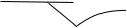


8
6
Names of Parts
|
TV Set |
|
Remote Control |
|
a |
q Main power |
1 |
f |
Power on/ |
|
on/off |
|
|
standby |
b |
Infrared sensor |
2 |
0~9 |
Direct select |
cq Power indicator 3 CHs/t Channel up/
|
d MENU Menu open |
|
|
down, |
|
|
e a |
TV/VIDEO |
|
|
Item select |
|
|
|
|
||
|
|
select |
4 ; –/+ Volume down/ |
||
|
f –;+ Volume down/ |
|
|
up, |
|
|
|
up, |
|
|
Menu select, |
|
|
Menu select, |
|
|
Level adjust |
|
|
Level adjust |
5 |
-/-- |
Digit select |
|
g tcs Channel down/ |
6 MENU Menu open |
|||
|
|
up, |
|||
|
|
|
|
|
|
|
|
Item select |
7 |
o |
Sound mute |
|
h l |
Headphone |
8 |
|
Picture control |
|
|
jack |
|
||
|
|
|
a |
|
|
|
i AUDIO Audio input |
9 |
TV/VIDEO |
||
|
|
|
select |
||
|
|
terminal |
|
|
|
|
|
|
|
|
|
|
j VIDEO Video input |
!º |
CALL |
On-screen on/ |
|
|
|
terminal |
|
|
off |
|
|
|
|
|
|
|
|
||||
Note: The shaded buttons are not |
|||||
|
available for your TV. |
|
|||
– 14 –

PROGRAMMING CHANNEL MEMORY
•For easy Channel selection, the chosen Position should have the same number as Channel stored there. For this operation, you may use the “SEARCH” and “SKIP” functions.
Example : Presetting Channel 12 to Position 12
Channel Preset
Auto search memory (ASM)
All the channels that can be received are preset automatically.
1 |
Select the starting position for ASM. Press (0~9) or CH |
s/t. |
|
|
|
2 |
Set the correct broadcast system for your region. Press |
MENU and ; –/+ to call up the “SET UP” menu D5 . |
|
|
Set “COLOR” to “AUTO” and set “SOUND” according |
|
to the table shown on Page 9 of Owner's Manual using |
|
CHs/t and ; –/+. |
|
|
3 |
Press MENU and ;–/+ to call up the “TUNING” menu |
D6 . Select “ASM”, then press ; + to start the search. |
When the TV screen returns to the start position, the procedure is complete.
Manual Search and Changing the assigned position
Manual Search
1 |
Select Position 12. |
|||
Press CH s/trepeatedly until 12 is displayed. Or, press |
||||
|
-/-- repeatedly to display “--” on the screen then press |
|||
|
the “1” and “2” buttons in this order. |
|||
|
|
|
|
|
2 |
Press MENU and ;–/+ to call up the “TUNING” menu |
|||
D6 |
. Press CH s/t and select “SEARCH”. |
|||
|
Press ; –/+ to search. Pressing “-” searches for chan- |
|||
|
nels at lower frequencies while pressing “+” searches |
|||
|
for channels at higher frequencies. |
|||
|
|
|
|
|
3 |
When Channel 12 is found, press CH s/t to select |
|||
“MEMORY”. Press “+” to complete the presetting. |
||||
Store Position |
||||
|
|
|
|
|
1 |
Select Channel 12. |
|||
Press (0~9) or CH s/t to find the position preset for |
||||
|
Channel 12. |
|||
|
|
|
|
|
2 |
When Channel 12 is selected, press MENU and |
|||
; –/+ to call up the “TUNING” menu |
D6 |
. Press CH |
||
|
s/tand select “POSITION”. Press ;–/+ and set “PO- |
|||
|
SITION” to P012. Pressing “-” and “+” respectively de- |
|||
|
creases and increases the position number. |
|||
|
|
|
|
|
3 |
When Position 12 is found, press CH s/t to select |
|||
“MEMORY”. Press “+” to complete the presetting. |
||||
SPECIFIC INFORMATIONS GENERAL ADJUSTMENTS
– 15 –

SPECIFIC INFORMATIONS GENERAL ADJUSTMENTS
•Under some reception conditions, fine tuning may be necessary to improve the picture quality. In such cases, adjust the manual fine tuning (MFT).
•If the signal frequency is unstable due to environmental conditions, use auto fine tuning.
Skip Function
If you set “SKIP ON” for unnecessary position numbers, these will be skipped when selecting channels using CH s/t. Example : Skipping Channel 13
1 |
Select Position 13 using the same method for select- |
ing Position 12 (previous page). |
|
|
|
2 |
Press MENU and ; –/+ to call up the “SET UP” menu |
D5 . Press CH s/t and select “SKIP”. |
Press ; –/+ to switch the “SKIP” setting from “OFF” to “ON”. This completes the setting for skipping Position 13.
Notes:
•When “SKIP” is ON, the Position number is prefixed by
“*”.
Example: *13. To confirm this, select Position 13 using the -/-- and 0~9 buttons.
•If you want to restore a skipped position number, select it using the -/-- and 0~9 buttons then switch the “SKIP” setting to “OFF” as in step 2 above.
Manual fine tuning (MFT)
1 |
Press MENU and ;–/+ to call up the “TUNING” menu |
D6 . |
|
|
|
2 |
Press CH s/t and select “MFT”. Press ; –/+ to start |
fine tuning. Pressing “-” fine tunes to a lower frequency |
while pressing “+” fine tunes to a higher frequency.
Auto fine tuning (AFT)
1 |
Press MENU and ; –/+ to call up the “TUNING” menu |
D6 . |
|
|
|
2 |
Press CH s/t and select “AFT”. Press ;–/+ to switch |
it to “ON”. This completes the setting. |
Notes:
•When you operate MFT, AFT is switched OFF automatically. If you switch on AFT after fine tuning with MFT, MFT may be cancelled.
•AFT may be set independently for each Position.
– 16 –

CHASSIS AND CABINET REPLACEMENT PARTS LIST
WARNING: BEFORE SERVICING THIS CHASSIS, READ THE “X-RAY RADIATION PRECAUTION”, “SAFETY PRECAUTION” AND “PRODUCT SAFETY NOTICE” ON PAGE 3 OF THIS MANUAL.
CAUTION: The international hazard symbols “  ” in the schematic diagram and the parts list designate components which have special characteristics important for safety and should be replaced only with types identical to those in the original circuit or specified in the parts list. The mounting position of replacements is to be identical with originals. Before replacing any of these components, read carefully the PRODUCT SAFETY NOTICE. Do not degrade the safety of the receiver through improper servicing.
NOTICE:
•The part number must be used when ordering parts, in order to assist in processing, be sure to include the Model number and Description.
•The PC board assembly with * mark is no longer available after the end of the production.
|
|
Model : 21SZ2E, 21SZ2ES, 21SZ2T, 21SZ2M, 21SZ2MJ |
|
|
|
||||
Capacitors ............. |
CD |
: |
Ceramic Disk |
PF |
: |
Plastic Film |
EL |
: |
Electrolytic |
Resistors ............... |
CF |
: |
Carbon Film |
CC |
: |
Carbon Composition |
MF |
: |
Metal Film |
|
OMF : |
Oxide Metal Film |
VR |
: |
Variable Resistor |
FR |
: |
Fusible Resistor |
|
(All CD and PF capacitors are ±5%, 50V and all resistors, ±5%, 1/6W unless otherwise noted.)
Location Parts No. Description
No.
CAPACITORS
C101 |
24797479 |
ELECTROLYTIC, 50V 4.7UF M |
C103 |
24797221 |
ELECTROLYTIC, 50V 220UF M |
C105 |
24109102 |
CERAMIC CHIP, 50V B 1000PF K |
C106 |
24797100 |
ELECTROLYTIC, 50V 10UF M |
C110 |
24797221 |
ELECTROLYTIC, 50V 220UF M |
C200 |
24793101 |
ELECTROLYTIC, 10V 100UF M |
C201 |
24092538 |
CERAMIC CHIP, 10V F 1UF Z |
C202 |
24092538 |
CERAMIC CHIP, 10V F 1UF Z |
C203 |
24092538 |
CERAMIC CHIP, 10V F 1UF Z |
C204 |
24793470 |
ELECTROLYTIC CE04G 10V 47UF M |
C205 |
24092538 |
CERAMIC CHIP, 10V F 1UF Z |
C207 |
24092538 |
CERAMIC CHIP, 10V F 1UF Z |
C210 |
24085949 |
ELEC. NONPOLAR CE04J 25V |
|
|
10UF M 11L NP |
C211 |
24092538 |
CERAMIC CHIP, 10V F 1UF Z |
C220 |
24591104 |
PLASTIC FILM, 50V 0.1UF J |
C221 |
24092538 |
CERAMIC CHIP, 10V F 1UF Z |
C303 |
24214471 |
CERAMIC DISC, 500V B 470PF K |
C306 |
24666332 |
ELECTROLYTIC, 16V 3300UF M 3A |
C308 |
24669101 |
ELECTROLYTIC, 50V 100UF M 3A |
C309 |
24669331 |
ELECTROLYTIC, 50V 330UF M 3A |
C310 |
24669222 |
ELECTROLYTIC, 50V 2200UF M 3A |
C311 |
24434100 |
CERAMIC DISC, 500V SL 10PF D |
C313 |
24082057 |
PLASTIC FILM, 100V 0.22UF J |
C314 |
24693472 |
PLASTIC FILM, 100V 4700PF J |
C315 |
24109102 |
CERAMIC CHIP, 50V B 1000PF K |
C320 |
24591682 |
PLASTIC FILM, 50V 6800PF J |
C322 |
24085980 |
ELECTROLYTIC, NONPOLAR, 16V |
|
|
22UF M 11L |
C323 |
24668101 |
ELECTROLYTIC, 35V 100UF M 3A |
C324 |
24668101 |
ELECTROLYTIC, 35V 100UF M 3A |
C325 |
24669010 |
ELECTROLYTIC, 50V 1UF M 3A |
C326 |
24591183 |
PLASTIC FILM, 50V 0.018UF J |
C341 |
24794101 |
ELECTROLYTIC, 16V 100UF M |
C342 |
24795100 |
ELECTROLYTIC, 25V 10UF M |
C363 |
24693473 |
PLASTIC FILM, 100V 0.047UF J |
C401 |
24108680 |
CERAMIC CHIP, 50V SL 68PF J |
C402 |
24693222 |
PLASTIC FILM, 100V 2200PF J |
C406 |
24109221 |
CERAMIC CHIP, 50V B 220PF K |
C407 |
24092730 |
CERAMIC CHIP, 16V B 0.1UF K |
C408 |
24108330 |
CERAMIC CHIP, 50V SL 33PF J |
Location |
Parts No. |
Description |
No. |
|
|
C409 |
24109103 |
CERAMIC CHIP, 50V B 0.01UF K |
C410 |
24794100 |
ELECTROLYTIC, 16V 10UF M |
C413 |
24214821 |
CERAMIC DISC, 500V B 820PF K |
C415 |
24109103 |
CERAMIC CHIP, 50V B 0.01UF K |
C416 |
24678229 |
ELECTROLYTIC, 200V 2.2UF M 3A |
C417 |
24214391 |
CERAMIC DISC, 500V B 390PF K |
C418 |
24109221 |
CERAMIC CHIP, 50V B 220PF K |
C419 |
24668101 |
ELECTROLYTIC, 35V 100UF M 3A |
C430 |
24092730 |
CERAMIC CHIP, 16V B 0.1UF K |
C431 |
24794101 |
ELECTROLYTIC, 16V 100UF M |
C440 |
24503193 |
PLASTIC FILM, 1500VH 1000PF H |
C442 |
24082995 |
PLASTIC FILM, 250V 0.36 UF J |
C444 |
24503279 |
PLASTIC FILM, 1500VH 9100PF H |
C445 |
24828563 |
PLASTIC FILM, 200V 56000PF J |
C447 |
24679220 |
ELECTROLYTIC, 250V 22UF M 3A |
C448 |
24640908 |
ELECTROLYTIC, 160V 33UF M 3A LI |
C449 |
24667102 |
ELECTROLYTIC, 25V 1000UF M 3A |
C463 |
24212222 |
CERAMIC DISC, 50V B 2200PF K |
C464 |
24640872 |
ELECTROLYTIC, 100V 10UF M 3A |
C467 |
24820433 |
PLASTIC FILM, 630V 0.043UF J |
C470 |
24797101 |
ELECTROLYTIC, 50V 100UF M |
C472 |
24539474 |
PLASTIC FILM, 50V 0.47UF J |
C475 |
24092730 |
CERAMIC CHIP, 16V B 0.1UF K |
C500 |
24092730 |
CERAMIC CHIP, 16V B 0.1UF K |
C501 |
24109103 |
CERAMIC CHIP, 50V B 0.01UF K |
C502 |
24793102 |
ELECTROLYTIC, 10V 1000UF M |
C503 |
24109103 |
CERAMIC CHIP, 50V B 0.01UF K |
C543 |
24794100 |
ELECTROLYTIC, 16V 10UF M |
C547 |
24793101 |
ELECTROLYTIC, 10V 100UF M |
C560 |
24794101 |
ELECTROLYTIC, 16V 100UF M |
C561 |
24109103 |
CERAMIC CHIP, 50V B 0.01UF K |
C624 |
24797478 |
ELECTROLYTIC, 50V 0.47UF M |
C664 |
24797478 |
ELECTROLYTIC, 50V 0.47UF M |
C670 |
24797470 |
ELECTROLYTIC, 50V 47UF M |
C671 |
24797471 |
ELECTROLYTIC, 50V 470UF M |
C672 |
24797229 |
ELECTROLYTIC, 50V 2.2UF M |
C677 |
24539823 |
PLASTIC FILM, 50V 0.082UF J |
C679 |
24539563 |
PLASTIC FILM, 50V 0.056UF J |
C680 |
24669229 |
ELECTROLYTIC, 50V 2.2UF M 3A |
C681 |
24669229 |
ELECTROLYTIC, 50V 2.2UF M 3A |
C682 |
24669229 |
ELECTROLYTIC, 50V 2.2UF M 3A |
C683 |
24795101 |
ELECTROLYTIC, 25V 100UF M |
|
|
|
SPECIFIC INFORMATIONS
– 17 –

SPECIFIC INFORMATIONS
Location |
Parts No. |
Description |
|
Location |
Parts No. |
Description |
No. |
|
|
|
No. |
|
|
C684 |
24503049 |
PLASTIC FILM, 63V 0.47UF J |
|
CA72 |
24105680 |
CERAMIC CHIP, 50V CH 68PF J |
C685 |
24797100 |
ELECTROLYTIC, 50V 10UF M |
|
CA73 |
24105680 |
CERAMIC CHIP, 50V CH 68PF J |
C686 |
24795102 |
ELECTROLYTIC, 25V 1000UF M |
|
CA74 |
24105101 |
CERAMIC CHIP, 50V CH 100PF J |
C687 |
24797100 |
ELECTROLYTIC, 50V 10UF M |
|
CA76 |
24797229 |
ELECTROLYTIC, 50V 2.2UF M |
C688 |
24503049 |
PLASTIC FILM, 63V 0.47UF J |
|
CA77 |
24092538 |
CERAMIC CHIP, 10V F 1UF Z |
C689 |
24667471 |
ELECTROLYTIC, 25V 470UF M 3A |
|
CA82 |
24793470 |
ELECTROLYTIC CE04G 10V 47UF M |
C690 |
24667471 |
ELECTROLYTIC, 25V 470UF M 3A |
|
CB01 |
24794470 |
ELECTROLYTIC, 16V 47UF M |
C739 |
24794100 |
ELECTROLYTIC, 16V 10UF M |
|
CB05 |
24666100 |
ELECTROLYTIC, 10V 10UF M 3A |
* C801 |
24503507 |
PLASTIC FILM, AC275V 0.22UF K |
|
CC01 |
24109103 |
CERAMIC CHIP, 50V B 0.01UF K |
C802 |
24503507 |
PLASTIC FILM, AC275V 0.22UF K |
|
CI01 |
24109103 |
CERAMIC CHIP, 50V B 0.01UF K |
C805 |
24092281 |
CERAMIC DISC, AC250V E 4700PF |
|
CI02 |
24109103 |
CERAMIC CHIP, 50V B 0.01UF K |
C806 |
24092281 |
CERAMIC DISC, AC250V E 4700PF |
|
CI03 |
24109103 |
CERAMIC CHIP, 50V B 0.01UF K |
C808 |
24668101 |
ELECTROLYTIC, 35V 100UF M 3A |
|
CI04 |
24109103 |
CERAMIC CHIP, 50V B 0.01UF K |
C810 |
24086857 |
ELECTROLYTIC, 400V 560UF |
|
|
|
(21SZ2E/21SZ2M/21SZ2MJ) |
C811 |
24092555 |
CERAMIC DISC, AC250V E 1000PF M |
|
CI05 |
24109103 |
CERAMIC CHIP, 50V B 0.01UF K |
* C813 |
24092555 |
CERAMIC DISC, AC250V E 1000PF M |
|
CI06 |
24109103 |
CERAMIC CHIP, 50V B 0.01UF K |
* C814 |
24092555 |
CERAMIC DISC, AC250V E 1000PF M |
|
CI08 |
24797010 |
ELECTROLYTIC, 50V 1UF M |
C815 |
24092551 |
CERAMIC DISC, AC250V B 220PF K |
|
CI09 |
24109103 |
CERAMIC CHIP, 50V B 0.01UF K |
C817 |
24092338 |
CERAMIC DISC, 2KV R 270PF K |
|
CI10 |
24794101 |
ELECTROLYTIC, 16V 100UF M |
C818 |
24092341 |
CERAMIC DISC, 2KV R 470PF K |
|
CI12 |
24092573 |
CERAMIC CHIP, 16V B 0.47UF K |
C821 |
24214561 |
CERAMIC DISC, 500V B 560PF K |
|
CI13 |
24109102 |
CERAMIC CHIP, 50V B 1000PF K |
C822 |
24214102 |
CERAMIC DISC, 500V B 1000PF K |
|
CI14 |
24109103 |
CERAMIC CHIP, 50V B 0.01UF K |
C823 |
24212471 |
CERAMIC DISC, 50V B 470PF K |
|
CI16 |
24105150 |
CERAMIC CHIP, 50V CH 15PF J |
C829 |
24212561 |
CERAMIC DISC, 50V B 560PF K |
|
CI17 |
24797229 |
ELECTROLYTIC, 50V 2.2UF M |
C830 |
24503047 |
PLASTIC FILM, 63V 0.33UF J |
|
CI18 |
24203220 |
ELECTROLYTIC, 16V 22UF M 7L 3A |
C831 |
24503047 |
PLASTIC FILM, 63V 0.33UF J |
|
CI20 |
24105560 |
CERAMIC CHIP, 50V CH 56PF J |
C832 |
24503047 |
PLASTIC FILM, 63V 0.33UF J |
|
CI21 |
24105430 |
CERAMIC CHIP CC73CH 50V 43PF J |
C834 |
24503047 |
PLASTIC FILM, 63V 0.33UF J |
|
CI30 |
24109103 |
CERAMIC CHIP, 50V B 0.01UF K |
C840 |
24666470 |
ELECTORLYTIC, 16V 47UF M 3A |
|
CI31 |
24797479 |
ELECTROLYTIC, 50V 4.7UF M |
C841 |
24503047 |
PLASTIC FILM, 63V 0.33UF J |
|
CI56 |
24105120 |
CERAMIC CHIP, 50V CH 12PF J |
C842 |
24503047 |
PLASTIC FILM, 63V 0.33UF J |
|
CI57 |
24105510 |
CERAMIC CHIP, 50V CH 51PF J |
C862 |
24092339 |
CERAMIC DISC, 2KV 330PF K |
|
CI60 |
24105470 |
CERAMIC CHIP, 50V CH 47PF J |
C883 |
24214561 |
CERAMIC DISC, 500V B 560PF K |
|
|
|
(21SZ2E/21SZ2M/21SZ2MJ) |
C884 |
24086052 |
ELECTRORYTIC, 200V 220UF M 22A |
|
CI61 |
24105470 |
CERAMIC CHIP, 50V CH 47PF J |
C885 |
24214471 |
CERAMIC DISC, 500V B 470PF K |
|
|
|
(21SZ2E/21SZ2M/21SZ2MJ) |
C889 |
24668222 |
ELECTROLYTIC, 35V 2200UF M 3A |
|
CI62 |
24109103 |
CERAMIC CHIP, 50V B 0.01UF K |
C891 |
24666102 |
ELECTROLYTIC, 16V 1000UF M 3A |
|
|
|
(21SZ2E/21SZ2M/21SZ2MJ) |
C893 |
24092337 |
CERAMIC DISC, 2KV 220PF K |
|
CI63 |
24109103 |
CERAMIC CHIP, 50V B 0.01UF K |
C898 |
24503045 |
PLASTIC FILM, 63V 0.22UF J |
|
CI65 |
24109153 |
CERAMIC CHIP, 50V B 0.015UF K |
C899 |
24214471 |
CERAMIC DISC, 500V B 470PF K |
|
CI71 |
24109103 |
CERAMIC CHIP, 50V B 0.01UF K |
C902 |
24092347 |
CERAMIC DISC, 2KV R 1500PF K |
|
CI81 |
24109103 |
CERAMIC CHIP, 50V B 0.01UF K |
C904 |
24436561 |
CERAMIC DISC, 50V SL 560PF J |
|
CI90 |
24105470 |
CERAMIC CHIP, 50V CH 47PF J |
C905 |
24436681 |
CERAMIC DISC, 50V SL 680PF J |
|
CI91 |
24105470 |
CERAMIC CHIP, 50V CH 47PF J |
C907 |
24436821 |
CERAMIC DISC, 50V SL 820PF J |
|
CI92 |
24109103 |
CERAMIC CHIP, 50V B 0.01UF K |
C909 |
24679220 |
ELECTROLYTIC, 250V 22UF M 3A |
|
CI93 |
24109103 |
CERAMIC CHIP, 50V B 0.01UF K |
C910 |
24797100 |
ELECTROLYTIC, 50V 10UF M |
|
CS11 |
24794100 |
ELECTROLYTIC, 16V 10UF M |
C912 |
24794471 |
ELECTROLYTIC, 16V 470UF M |
|
CS12 |
24794220 |
ELECTROLYTIC, 16V 22UF M |
C913 |
24794220 |
ELECTROLYTIC, 16V 22UF M |
|
CS13 |
24794220 |
ELECTROLYTIC, 16V 22UF M |
C915 |
24794220 |
ELECTROLYTIC, 16V 22UF M |
|
CS15 |
24109103 |
CERAMIC CHIP, 50V B 0.01UF K |
C930 |
24214101 |
CERAMIC DISC, 500V B 100PF K |
|
CS29 |
24794220 |
ELECTROLYTIC, 16V 22UF M |
C931 |
24214101 |
CERAMIC DISC, 500V B 100PF K |
|
CV13 |
24085942 |
ELECTROLYTIC, NONPOLAR, 16V 10UF M 5L |
C4300 |
24109103 |
CERAMIC CHIP, 50V B 0.01UF K |
|
CV14 |
24794100 |
ELECTROLYTIC, 16V 10UF M |
C4712 |
24109103 |
CERAMIC CHIP, 50V B 0.01UF K |
|
CV34 |
24762471 |
ELECTROLYTIC, 10V 470UF M |
CA09 |
24109103 |
CERAMIC CHIP, 50V B 0.01UF K |
|
CV36 |
24794221 |
ELECTROIYTIC, 16V 220UF M |
CA14 |
24105680 |
CERAMIC CHIP, 50V CH 68PF J |
|
|
|
|
CA15 |
24105680 |
CERAMIC CHIP, 50V CH 68PF J |
|
RESISTORS |
|
|
CA48 |
24105221 |
CERAMIC CHIP, 50V CH 220PF J |
|
R101 |
24553153 |
OXIDE METAL FILM, 1W 15K OHM J |
CA49 |
24794100 |
ELECTROLYTIC, 16V 10UF M |
|
R121 |
24011472 |
CHIP, METAL FILM, 1/20W 4.7K OHM J |
CA50 |
24105270 |
CERAMIC CHIP, 50V CH 27PF J |
|
R205 |
24011821 |
CHIP, METAL FILM, 1/20W 820 OHM J |
CA51 |
24105270 |
CERAMIC CHIP, 50V CH 27PF J |
|
R206 |
24011472 |
CHIP, METAL FILM, 1/20W 4.7K OHM J |
CA53 |
24105101 |
CERAMIC CHIP, 50V CH 100PF J |
|
R207 |
24011821 |
CHIP, METAL FILM, 1/20W 820 OHM J |
CA54 |
24092730 |
CERAMIC CHIP, 16V B 0.1UF K |
|
R210 |
24011272 |
CHIP, METAL FILM, 1/20W 2.7K OHM J |
CA55 |
24105101 |
CERAMIC CHIP, 50V CH 100PF J |
|
R212 |
24011273 |
CHIP, METAL FILM, 1/20W 27K OHM J |
CA56 |
24105101 |
CERAMIC CHIP, 50V CH 100PF J |
|
R215 |
24011362 |
CHIP, METAL FILM, 1/20W 3.6K OHM J |
CA60 |
24092538 |
CERAMIC CHIP, 10V F 1UF Z |
|
R217 |
24366103 |
CARBON FILM, 1/6W 10K OHM J |
CA61 |
24793101 |
ELECTROLYTIC, 10V 100UF M |
|
R218 |
24367272 |
CARBON FILM, 1/6W 2.7K OHM J |
CA65 |
24092729 |
CERAMIC CHIP CK73B 16V 68000PFK |
|
R219 |
24011682 |
CHIP, METAL FILM, 1/20W 6.8K OHM J |
|
|
|
|
|
|
|
– 18 –

Location |
Parts No. |
Description |
No. |
|
|
R220 |
24011822 |
CHIP, METAL FILM, 1/20W 8.2K OHM J |
R221 |
24011821 |
CHIP, METAL FILM, 1/20W 820 OHM J |
R222 |
24011681 |
CHIP, METAL FILM, 1/20W 680 OHM J |
R227 |
24367113 |
CARBON FILM, 1/2W 11K OHM J |
R231 |
24011622 |
CHIP, METAL FILM, 1/20W 6.2K OHM J |
R232 |
24011123 |
CHIP, METAL FILM, 1/20W 12K OHM J |
R233 |
24367273 |
CARBON FILM, 1/6W 27K OHM G |
R303 |
24321229 |
OXIDE METAL FILM, 1/2W 2.2 OHM J |
R305 |
24322109 |
OXIDE METAL FILM, 1W 1 OHM J |
R314 |
24011562 |
CHIP, METAL FILM, 1/20W 5.6K OHM J |
R319 |
24000445 |
CHIP JUMPER, 1608TYPE |
R320 |
24011103 |
CHIP, METAL FILM, 1/20W 10K OHM J |
R321 |
24000445 |
CHIP JUMPER, 1608TYPE |
R322 |
24011912 |
CHIP, METAL FILM, 1/20W 9.1K OHM J |
R323 |
24011472 |
CHIP, METAL FILM, 1/20W 4.7K OHM J |
R324 |
24011182 |
CHIP, METAL FILM, 1/20W 1.8K OHM J |
R325 |
24011752 |
CHIP, METAL FILM, 1/20W 7.5K OHM J |
R326 |
24367272 |
CARBON FILM, 1/6W 2.7K OHM J |
R327 |
24323159 |
OXIDE METAL FILM, 2W 1.5 OHM J |
R328 |
24367392 |
CARBON FILM, 1/6W 3.9K OHM G |
R329 |
24000633 |
METAL FILM, 1/4W 10K OHM F |
R330 |
24000245 |
METAL FILM, 1/4W 33K OHM F |
R331 |
24000634 |
METAL FILM, 1/4W 11K OHM F |
R336 |
24383181 |
OXIDE METAL FILM, 2W 180 OHM J |
R341 |
24011182 |
CHIP, METAL FILM, 1/20W 1.8K OHM J |
R342 |
24366562 |
CARBON FILM, 1/6W 5.6K OHM J |
R343 |
24310189 |
OXIDE METAL FILM, 1/2W 1.8 OHM J |
R344 |
24366392 |
CARBON FILM, 1/6W 3.9K OHM J |
R349 |
24011473 |
CHIP, METAL FILM, 1/20W 47K OHM J |
R401 |
24011471 |
CHIP, METAL FILM, 1/20W 470 OHM J |
R402 |
24011471 |
CHIP, METAL FILM, 1/20W 470 OHM J |
R403 |
24382123 |
OXIDE METAL FILM, 1W 12K OHM J |
R404 |
24011680 |
CHIP, METAL FILM, 1/20W 68 OHM J |
R405 |
24011222 |
CHIP, METAL FILM, 1/20W 2.2K OHM J |
R406 |
24011682 |
CHIP, METAL FILM, 1/20W 6.8K OHM J |
R407 |
24011223 |
CHIP, METAL FILM, 1/20W 22K OHM J |
R408 |
24011471 |
CHIP, METAL FILM, 1/20W 470 OHM J |
R409 |
24011101 |
CHIP, METAL FILM, 1/20W 100 OHM J |
R410 |
24872102 |
CHIP, METAL FILM, 1/16W 1K OHM J |
R411 |
24011470 |
CHIP, METAL FILM, 1/20W 47 OHM J |
R415 |
24553272 |
OXIDE METAL FILM, 1W 2.7K OHM J |
R416 |
24019330 |
OXIDE METAL FILM, 5W 3.6K OHM J |
R417 |
24011104 |
CHIP, METAL FILM, 1/20W 100K OHM J |
R418 |
24011103 |
CHIP, METAL FILM, 1/20W 10K OHM J |
R420 |
24011101 |
CHIP, METAL FILM, 1/20W 100 OHM J |
R424 |
24011103 |
CHIP, METAL FILM, 1/20W 10K OHM J |
R425 |
24011103 |
CHIP, METAL FILM, 1/20W 10K OHM J |
R431 |
24011103 |
CHIP, METAL FILM, 1/20W 10K OHM J |
R432 |
24366332 |
CARBON FILM, 1/6W 3.3K OHM J |
R433 |
24531680 |
FUSIBLE, 1/2W 68 OHM J |
R434 |
24366101 |
CARBON FILM, 1/6W 100 OHM J |
R441 |
24532102 |
FUSIBLE, 1W 1K OHM J |
R448 |
24338398 |
OXIDE METAL FILM, 1W 0.39 OHM J |
R470 |
24338688 |
OXIDE METAL FILM, 1W 0.68 OHM J |
R471 |
24381820 |
OXIDE METAL FILM, 1/2W 82 OHM J |
R473 |
24000637 |
METAL FILM, 1/4W 15K OHM F |
R474 |
24383910 |
OXIDE METAL FILM, 2W 91 OHM J |
R479 |
24381331 |
OXIDE FILM, 1/2W 330 J |
R501 |
24011562 |
CHIP, METAL FILM, 1/20W 5.6K OHM J |
R502 |
24011152 |
CHIP, METAL FILM, 1/20W 1.5K OHM J |
R512 |
24011121 |
CHIP, METAL FILM, 1/20W 120 OHM J |
R513 |
24011121 |
CHIP, METAL FILM, 1/20W 120 OHM J |
R515 |
24011472 |
CHIP, METAL FILM, 1/20W 4.7K OHM J |
R520 |
24011101 |
CHIP, METAL FILM, 1/20W 100 OHM J |
R521 |
24011101 |
CHIP, METAL FILM, 1/20W 100 OHM J |
R522 |
24011101 |
CHIP, METAL FILM, 1/20W 100 OHM J |
R544 |
24011333 |
CHIP, METAL FILM, 1/20W 33K OHM J |
|
|
|
Location |
Parts No. |
Description |
No. |
|
|
R545 |
24011121 |
CHIP, METAL FILM, 1/20W 120 OHM J |
R623 |
24011103 |
CHIP, METAL FILM, 1/20W 10K OHM J |
R624 |
24011104 |
CHIP, METAL FILM, 1/20W 100K OHM J |
R660 |
24011103 |
CHIP, METAL FILM, 1/20W 10K OHM J |
R661 |
24011103 |
CHIP, METAL FILM, 1/20W 10K OHM J |
R662 |
24011103 |
CHIP, METAL FILM, 1/20W 10K OHM J |
R663 |
24011103 |
CHIP, METAL FILM, 1/20W 10K OHM J |
R664 |
24011152 |
CHIP, METAL FILM, 1/20W 1.5K OHM J |
R668 |
24011273 |
CHIP, METAL FILM, 1/20W 27K OHM J |
R669 |
24011272 |
CHIP, METAL FILM, 1/20W 2.7K OHM J |
R671 |
24011103 |
CHIP, METAL FILM, 1/20W 10K OHM J |
R672 |
24011103 |
CHIP, METAL FILM, 1/20W 10K OHM J |
R673 |
24011104 |
CHIP, METAL FILM, 1/20W 100K OHM J |
R674 |
24011103 |
CHIP, METAL FILM, 1/20W 10K OHM J |
R675 |
24011104 |
CHIP, METAL FILM, 1/20W 100K OHM J |
R690 |
24011103 |
CHIP, METAL FILM, 1/20W 10K OHM J |
R691 |
24011103 |
CHIP, METAL FILM, 1/20W 10K OHM J |
* R801 |
24009954 |
METAL FILN, 1/2W 2.2M OHM J |
R802 |
24383104 |
OXIDE METAL FILM, 2W 100K OHM J |
R805 |
24366681 |
CARBON FILM, 1/6W 680 OHM J |
R807 |
24376684 |
CARBON RES B 1/2W 684J |
* R808 |
24019476 |
THERMISTOR, POSITIVE, AC290V 18 OHM M |
R809 |
24376433 |
CARBON RES B 1/2W 433J |
R810 |
24007737 |
CERAMIC COVERED, 15W 2.2 OHM J |
R811 |
24568271 |
CERAMIC COVERED, 7W 270 OHM J |
R815 |
24366562 |
CARBON FILM, 1/6W 5.6K OHM J |
R820 |
24019463 |
METAL PLATE RK99, 2W R22 J |
R821 |
24310479 |
OXIDE METAL FILM, 1/2W 4.7 OHM J |
R823 |
24376152 |
CARBON FILM, 1/2W 1.5K OHM J |
R827 |
24366102 |
CARBON FILM, 1/6W 1K OHM J |
R829 |
24988027 |
METAL FILM, 1W R47 J |
R840 |
24366471 |
CARBON FILM, 1/6W 470 OHM J |
R842 |
24366332 |
CARBON FILM, 1/6W 3.3K OHM J |
R843 |
24366471 |
CARBON FILM, 1/6W 470 OHM J |
R844 |
24321478 |
OXIDE METAL FILM, 1/2W 0.47 OHM J |
R863 |
24366132 |
CARBON FILM, 1/6W 1.3K OHM J |
R865 |
24366332 |
CARBON FILM, 1/6W 3.3K OHM J |
R868 |
24366472 |
CARBON FILM, 1/6W 4.7K OHM J |
R898 |
24321228 |
OXIDE METAL FILM, 1/2W 0.22 OHM J |
* R899 |
24004718 |
METAL GLAZE, 1/2W 8R2M J |
R901 |
24376102 |
CARBON FILM, 1/2W 1K OHM J |
R902 |
24376102 |
CARBON FILM, 1/2W 1K OHM J |
R903 |
24376102 |
CARBON FILM, 1/2W 1K OHM J |
R904 |
24366472 |
CARBON FILM, 1/6W 4.7K OHM J |
R905 |
24366150 |
CARBON FILM, 1/6W 15 OHM J |
R912 |
24366102 |
CARBON FILM, 1/6W 1K OHM J |
R914 |
24366561 |
CARBON FILM, 1/6W 560 OHM J |
R915 |
24366121 |
CARBON FILM, 1/6W 120 OHM J |
R916 |
24366181 |
CARBON FILM, 1/6W 180 OHM J |
R917 |
24366821 |
CARBON FILM, 1/6W 820 OHM J |
R918 |
24366270 |
CARBON FILM, 1/6W 27 OHM J |
R919 |
24366102 |
CARBON FILM, 1/6W 1K OHM J |
R920 |
24000874 |
FUSE 1W 439J |
R921 |
24366561 |
CARBON FILM, 1/6W 560 OHM J |
R922 |
24366121 |
CARBON FILM, 1/6W 120 OHM J |
R924 |
24366270 |
CARBON FILM, 1/6W 27 OHM J |
R925 |
24366821 |
CARBON FILM, 1/6W 820 OHM J |
R926 |
24366102 |
CARBON FILM, 1/6W 1K OHM J |
R928 |
24366561 |
CARBON FILM, 1/6W 560 OHM J |
R929 |
24366121 |
CARBON FILM, 1/6W 120 OHM J |
R930 |
24366270 |
CARBON FILM, 1/6W 27 OHM J |
R932 |
24366102 |
CARBON FILM, 1/6W 1K OHM J |
R934 |
24366561 |
CARBON FILM, 1/6W 560 OHM J |
R935 |
24366392 |
CARBON FILM, 1/6W 3.9K OHM J |
R936 |
24552820 |
OXIDE METAL FILM, 1/2W 82 OHM J |
R937 |
24366821 |
CARBON FILM, 1/6W 820 OHM J |
R942 |
24366562 |
CARBON FILM, 1/6W 5.6K OHM J |
|
|
|
SPECIFIC INFORMATIONS
– 19 –

SPECIFIC INFORMATIONS
Location |
Parts No. |
Description |
No. |
|
|
R943 |
24366562 |
CARBON FILM, 1/6W 5.6K OHM J |
R944 |
24366562 |
CARBON FILM, 1/6W 5.6K OHM J |
R945 |
24366181 |
CARBON FILM, 1/6W 180 OHM J |
R946 |
24366181 |
CARBON FILM, 1/6W 180 OHM J |
R960 |
24383153 |
OXIDE METAL FILM, 2W 15K OHM J |
R961 |
24383153 |
OXIDE METAL FILM, 2W 15K OHM J |
R962 |
24383153 |
OXIDE METAL FILM, 2W 15K OHM J |
R977 |
24366122 |
CARBON FILM, 1/6W 1.2K OHM J |
R992 |
24366150 |
CARBON FILM, 1/6W 15 OHM J |
R4711 |
24011684 |
CHIP, METAL FILM, 1/20W 680K OHM J |
R4712 |
24011224 |
CHIP, METAL FILM, 1/20W 220K OHM J |
R4715 |
24011102 |
CHIP, METAL FILM, 1/20W 1K OHM J |
R4716 |
24011333 |
CHIP, METAL FILM, 1/20W 33K OHM J |
R4760 |
24000247 |
METAL FILM, 1/4W 39K OHM F |
R4770 |
24011102 |
CHIP, METAL FILM, 1/20W 1K OHM J |
RA03 |
24011101 |
CHIP, METAL FILM, 1/20W 100 OHM J |
RA04 |
24011101 |
CHIP, METAL FILM, 1/20W 100 OHM J |
RA05 |
24011101 |
CHIP, METAL FILM, 1/20W 100 OHM J |
RA11 |
24011472 |
CHIP, METAL FILM, 1/20W 4.7K OHM J |
RA12 |
24011472 |
CHIP, METAL FILM, 1/20W 4.7K OHM J |
RA40 |
24366683 |
CARBON FILM, 1/6W 68K OHM J |
RA41 |
24366223 |
CARBON FILM, 1/6W 22K OHM J |
RA42 |
24366103 |
CARBON FILM, 1/6W 10K OHM J |
RA43 |
24366103 |
CARBON FILM, 1/6W 10K OHM J |
RA44 |
24366223 |
CARBON FILM, 1/6W 22K OHM J |
RA45 |
24366683 |
CARBON FILM, 1/6W 68K OHM J |
RA49 |
24011222 |
CHIP, METAL FILM, 1/20W 2.2K OHM J |
RA50 |
24011680 |
CHIP, METAL FILM, 1/20W 68 OHM J |
RA53 |
24011471 |
CHIP, METAL FILM, 1/20W 470 OHM J |
RA54 |
24011102 |
CHIP, METAL FILM, 1/20W 1K OHM J |
RA55 |
24011102 |
CHIP, METAL FILM, 1/20W 1K OHM J |
RA56 |
24011102 |
CHIP, METAL FILM, 1/20W 1K OHM J |
RA59 |
24011333 |
CHIP, METAL FILM, 1/20W 33K OHM J |
RA64 |
24011333 |
CHIP, METAL FILM, 1/20W 33K OHM J |
RA65 |
24011333 |
CHIP, METAL FILM, 1/20W 33K OHM J |
RA66 |
24011333 |
CHIP, METAL FILM, 1/20W 33K OHM J |
RA67 |
24011102 |
CHIP, METAL FILM, 1/20W 1K OHM J |
RA68 |
24011333 |
CHIP, METAL FILM, 1/20W 33K OHM J |
RA69 |
24011101 |
CHIP, METAL FILM, 1/20W 100 OHM J |
RA70 |
24011101 |
CHIP, METAL FILM, 1/20W 100 OHM J |
RA71 |
24011103 |
CHIP, METAL FILM, 1/20W 10K OHM J |
RA72 |
24011472 |
CHIP, METAL FILM, 1/20W 4.7K OHM J |
RA73 |
24011103 |
CHIP, METAL FILM, 1/20W 10K OHM J |
RA74 |
24011222 |
CHIP, METAL FILM, 1/20W 2.2K OHM J |
RA75 |
24011123 |
CHIP, METAL FILM, 1/20W 12K OHM J |
RA76 |
24011472 |
CHIP, METAL FILM, 1/20W 4.7K OHM J |
RA77 |
24011123 |
CHIP, METAL FILM, 1/20W 12K OHM J |
RA78 |
24011183 |
CHIP, METAL FILM, 1/20W 18K OHM J |
RA79 |
24011333 |
CHIP, METAL FILM, 1/20W 33K OHM J |
RB01 |
24366271 |
CARBON FILM, 1/6W 270 OHM J |
RB05 |
24011102 |
CHIP, METAL FILM, 1/20W 1K OHM J |
RB09 |
24366470 |
CARBON FILM, 1/6W 47 OHM J |
RB48 |
24011332 |
CHIP, METAL FILM, 1/20W 3.3K OHM J |
RB49 |
24011102 |
CHIP, METAL FILM, 1/20W 1K OHM J |
RC11 |
24000445 |
CHIP JUMPER, 1608TYPE |
RC16 |
24000445 |
CHIP JUMPER, 1608TYPE |
RI01 |
24011330 |
CHIP, METAL FILM, 1/20W 33 OHM J |
RI02 |
24011682 |
CHIP, METAL FILM, 1/20W 6.8K OHM J |
RI03 |
24011272 |
CHIP, METAL FILM, 1/20W 2.7K OHM J |
RI04 |
24011330 |
CHIP, METAL FILM, 1/20W 33 OHM J |
RI05 |
24011751 |
CHIP, METAL FILM, 1/20W 750 OHM J |
RI06 |
24011330 |
CHIP, METAL FILM, 1/20W 33 OHM J |
RI07 |
24871390 |
METAL FILM CHIP, 1/8W 39 J |
RI08 |
24011821 |
CHIP, METAL FILM, 1/20W 820 OHM J |
RI09 |
24011102 |
CHIP, METAL FILM, 1/20W 1K OHM J |
RI10 |
24011103 |
CHIP, METAL FILM, 1/20W 10K OHM J |
|
|
(21SZ2E/21SZ2M/21SZ2MJ) |
|
|
|
Location |
Parts No. |
Description |
No. |
|
|
RI11 |
24011302 |
CHIP, METAL FILM, 1/20W 3K OHM J |
|
|
(21SZ2E/21SZ2M/21SZ2MJ) |
RI12 |
24011103 |
CHIP, METAL FILM, 1/20W 10K OHM J |
|
|
(21SZ2E/21SZ2M/21SZ2MJ) |
RI13 |
24011332 |
CHIP, METAL FILM, 1/20W 3.3K OHM J |
|
|
(21SZ2E/21SZ2M/21SZ2MJ) |
RI14 |
24000445 |
CHIP JUMPER, 1608TYPE |
RI15 |
24011103 |
CHIP, METAL FILM, 1/20W 10K OHM J |
|
|
(21SZ2E/21SZ2M/21SZ2MJ) |
RI16 |
24011101 |
CHIP, METAL FILM, 1/20W 100 OHM J |
RI17 |
24011301 |
CHIP, METAL FILM, 1/20W 300 OHM J |
|
|
(21SZ2E/21SZ2M/21SZ2MJ) |
RI18 |
24011331 |
CHIP, METAL FILM, 1/20W 330 OHM J |
RI19 |
24011105 |
CHIP, METAL FILM, 1/20W 1M OHM J |
RI20 |
24011821 |
CHIP, METAL FILM, 1/20W 820 OHM J |
RI21 |
24011271 |
CHIP, METAL FILM, 1/20W 270 OHM J |
RI30 |
24011473 |
CHIP, METAL FILM, 1/20W 47K OHM J |
RI31 |
24011433 |
CHIP, METAL FILM, 1/20W 43K OHM J |
RI32 |
24011133 |
CHIP, METAL FILM, 1/20W 13K OHM J |
RI33 |
24011152 |
CHIP, METAL FILM, 1/20W 1.5K OHM J |
RI40 |
24011104 |
CHIP, METAL FILM, 1/20W 100K OHM J |
|
|
(21SZ2E/21SZ2M/21SZ2MJ) |
RI41 |
24011102 |
CHIP, METAL FILM, 1/20W 1K OHM J |
RI42 |
24011112 |
CHIP, METAL FILM, 1/20W 1.1K OHM J |
RI43 |
24011561 |
CHIP, METAL FILM, 1/20W 560 OHM J |
RI44 |
24011471 |
CHIP, METAL FILM, 1/20W 470 OHM J |
RI45 |
24011561 |
CHIP, METAL FILM, 1/20W 560 OHM J |
RI46 |
24011122 |
CHIP, METAL FILM, 1/20W 1.2K OHM J |
RI47 |
24011101 |
CHIP, METAL FILM, 1/20W 100 OHM J |
RI51 |
24066046 |
VARIABLE. CARBON, 0.1W 20K N |
RI52 |
24011331 |
CHIP, METAL FILM, 1/20W 330 OHM J |
RI61 |
24011102 |
CHIP, METAL FILM, 1/20W 1K OHM J |
|
|
(21SZ2E/21SZ2M/21SZ2MJ) |
RI62 |
24011102 |
CHIP, METAL FILM, 1/20W 1K OHM J |
|
|
(21SZ2E/21SZ2M/21SZ2MJ) |
RI63 |
24011102 |
CHIP, METAL FILM, 1/20W 1K OHM J |
RI65 |
24011222 |
CHIP, METAL FILM, 1/20W 2.2K OHM J |
RI67 |
24011563 |
CHIP, METAL FILM, 1/20W 56K OHM J |
|
|
(21SZ2E/21SZ2M/21SZ2MJ) |
RI68 |
24011563 |
CHIP, METAL FILM, 1/20W 56K OHM J |
RI69 |
24011102 |
CHIP, METAL FILM, 1/20W 1K OHM J |
RI71 |
24011134 |
CHIP, METAL FILM, 1/2OW 130K OHM J |
RI72 |
24011134 |
CHIP, METAL FILM, 1/2OW 130K OHM J |
RI73 |
24011303 |
CHIP, METAL FILM, 1/20W 30K OHM J |
RI74 |
24011223 |
CHIP, METAL FILM, 1/20W 22K OHM J |
RI77 |
24011102 |
CHIP, METAL FILM, 1/20W 1K OHM J |
RI78 |
24011102 |
CHIP, METAL FILM, 1/20W 1K OHM J |
RI79 |
24011333 |
CHIP, METAL FILM, 1/20W 33K OHM J |
RI80 |
24011183 |
CHIP, METAL FILM, 1/20W 18K OHM J |
RI81 |
24011301 |
CHIP, METAL FILM, 1/20W 300 OHM J |
RI82 |
24011101 |
CHIP, METAL FILM, 1/20W 100 OHM J |
RI83 |
24011103 |
CHIP, METAL FILM, 1/20W 10K OHM J |
RI84 |
24011472 |
CHIP, METAL FILM, 1/20W 4.7K OHM J |
RI85 |
24011472 |
CHIP, METAL FILM, 1/20W 4.7K OHM J |
RI87 |
24011472 |
CHIP, METAL FILM, 1/20W 4.7K OHM J |
RI88 |
24011203 |
CHIP, METAL FILM, 1/20W 20K OHM J |
RI91 |
24011102 |
CHIP, METAL FILM, 1/20W 1K OHM J |
RI97 |
24011563 |
CHIP, METAL FILM, 1/20W 56K OHM J |
RI98 |
24011563 |
CHIP, METAL FILM, 1/20W 56K OHM J |
RI99 |
24011102 |
CHIP, METAL FILM, 1/20W 1K OHM J |
RS01 |
24011103 |
CHIP, METAL FILM, 1/20W 10K OHM J |
RS02 |
24011104 |
CHIP, METAL FILM, 1/20W 100K OHM J |
RS11 |
24011102 |
CHIP, METAL FILM, 1/20W 1K OHM J |
RS21 |
24011102 |
CHIP, METAL FILM, 1/20W 1K OHM J |
RS22 |
24011222 |
CHIP, METAL FILM, 1/20W 2.2K OHM J |
RS24 |
24011102 |
CHIP, METAL FILM, 1/20W 1K OHM J |
RS27 |
24011561 |
CHIP, METAL FILM, 1/20W 560 OHM J |
|
|
|
– 20 –
Location |
Parts No. |
Description |
No. |
|
|
RS61 |
24552221 |
OXIDE METAL FILM, 1/2W 220 OHM J |
RS62 |
24552221 |
OXIDE METAL FILM, 1/2W 220 OHM J |
RV02 |
24366223 |
CARBON FILM, 1/6W 22K OHM J |
RV06 |
24011472 |
CHIP, METAL FILM, 1/20W 4.7K OHM J |
RV17 |
24366750 |
CARBON FILM, 1/6W 75 OHM J |
RV18 |
24011102 |
CHIP, METAL FILM, 1/20W 1K OHM J |
RV21 |
24011151 |
CHIP, METAL FILM, 1/20W 150 OHM J |
RV24 |
24552101 |
OXIDE METAL FILM, 1/2W 100 OHM J |
RV25 |
24011750 |
CHIP, METAL FILM, 1/20W 75 OHM J |
RV26 |
24011101 |
CHIP, METAL FILM, 1/20W 100 OHM J |
COILS & TRANSFORMERS
L101 |
23248296 |
COIL, CHOKE, TLN3278GH |
L301 |
23103249 |
CORE, FERRITE BEAD 3.5X4.5, TEM2011AO |
L320 |
23103249 |
CORE, FERRITE BEAD 3.5X4.5, TEM2011AO |
L441 |
23233999 |
COIL, LINEALITY, TLN2215AY |
L461 |
23248177 |
COIL, CHOKE, TLN3337AD |
L462 |
23231345 |
COIL, DEFLECTION YOKE, 21FFG02 |
L462A |
23993696 |
B0ARD, CORRECTION |
L462B |
23949616 |
CONVER CORRECTOR, YV TC-R |
L462C |
23993081 |
METAL SHEET, CONV. CORRECTION, |
|
|
TCRMXH01H |
L462D |
23948535 |
SHEET, MAGNETIC FERRITE |
L462E |
23948536 |
SHEET, MAGNETIC FERRITE |
L501 |
23289924 |
COIL, PEAKING COIL 33MMH, TRF4330AU |
L502 |
23289924 |
COIL, PEAKING COIL 33MMH, TRF4330AU |
L503 |
23289924 |
COIL, PEAKING COIL 33MMH, TRF4330AU |
L505 |
23289843 |
COIL, PEAKING, TRF4330AT |
L506 |
23103249 |
CORE, FERRITE BEAD 3.5X4.5, TEM2011AO |
L507 |
23289924 |
COIL, PEAKING COIL 33MMH, TRF4330AU |
L805 |
23248234 |
COIL, CHOKE, TLN3481AC |
L806 |
23248234 |
COIL, CHOKE, TLN3481AC |
L810 |
23103279 |
FILTER, FERRITR CHOKE 3.5X5X2, |
|
|
TEM2014AO |
L811 |
23103279 |
FILTER, FERRITR CHOKE 3.5X5X2, |
|
|
TEM2014AO |
L883 |
23103249 |
CORE, FERRITE BEAD 3.5X4.5, TEM2011AO |
L885 |
23248288 |
COIL, CHOKE, TLN3299GH |
L886 |
23103249 |
CORE, FERRITE BEAD 3.5X4.5, TEM2011AO |
L888 |
23280016 |
COIL, PEAKING, TRF4100AZ |
L889 |
23280016 |
COIL, PEAKING, TRF4100AZ |
L891 |
23103249 |
CORE, FERRITE BEAD 3.5X4.5, TEM2011AO |
L893 |
23280016 |
COIL, PEAKING, TRF4100AZ |
L900 |
23103249 |
CORE, FERRITE BEAD 3.5X4.5, TEM2011AO |
* L901 |
23200534 |
COIL, DG-0.37, TSB-2301AH |
L902 |
23289221 |
COIL, PEAKING, TRF4221AF |
L903 |
23289221 |
COIL, PEAKING, TRF4221AF |
L904 |
23289221 |
COIL, PEAKING, TRF4221AF |
L905 |
23289390 |
COIL, PEAKING, TRF4390AF |
L906 |
23289390 |
COIL, PEAKING, TRF4390AF |
L907 |
23289390 |
COIL, PEAKING, TRF4390AF |
LA01 |
23103249 |
CORE, FERRITE BEAD 3.5X4.5, TEM2011AO |
LA02 |
23238506 |
COIL, PEAKING, TRF4229AJ |
LA102 |
23238506 |
COIL, PEAKING, TRF4229AJ |
LA72 |
23238506 |
COIL, PEAKING, TRF4229AJ |
LA73 |
23238506 |
COIL, PEAKING, TRF4229AJ |
LI01 |
23238554 |
COIL, PEAKING, TRF4R22AJ |
LI03 |
23238503 |
COIL, PEAKING, TRF4129AJ |
LI04 |
23238706 |
COIL, PEAKING, TRF4470AJ |
LI06 |
23238715 |
COIL, PEAKING, TRF4829AJ |
LI07 |
23238712 |
COIL, PEAKING, TRF4150AJ |
|
|
(21SZ2E/21SZ2M/21SZ2MJ) |
LI10 |
23289270 |
COIL, PEAKING, TRF4270AF |
LI51 |
23232032 |
COIL, VARIABLE, TRF3546D |
LI56 |
23238562 |
COIL, PEAKING, TRF4109AJ |
LI57 |
23238562 |
COIL, PEAKING, TRF4109AJ |
Location |
Parts No. |
Description |
No. |
|
|
LI61 |
23238710 |
COIL, PEAKING, TRF4220AJ |
|
|
(21SZ2E/21SZ2M/21SZ2MJ) |
LI91 |
23238713 |
COIL, PEAKING, TRF4120AJ |
T401 |
23224380 |
TRANSFORMER, HORIZ DRIVE, TLN1098GH |
* T461Z |
23236612 |
TRANSFORMER, HORIZ OUTPUT, SERVICE, |
|
|
TFB4159ZD |
T801 |
23211773 |
COIL, LINE FILTER, TRF 3164AF |
T802 |
23211771 |
COIL, LINE FILTER, TRF3202AF |
* T862 |
23217638 |
TRANSFORMER, TPW3534AM |
SEMICONDUCTORS
Q104 |
70200934 |
IC, IC RESET, PST9129N |
Q192 |
23205140 |
TRANSISTOR, DTC114EUAT106 |
Q205 |
23314204 |
TRANSISTOR, 2SC2412K,Q |
Q208 |
23314204 |
TRANSISTOR, 2SC2412K,Q |
Q210 |
23314204 |
TRANSISTOR, 2SC2412K,Q |
Q211 |
23314204 |
TRANSISTOR, 2SC2412K,Q |
Q301 |
23009352 |
IC, AN5522 |
Q301B |
70391355 |
SCREW, BIND HEAD TAP-TITE B, |
|
|
BITTB 3X8 SZN |
Q320 |
23314204 |
TRANSISTOR, 2SC2412K,Q |
Q321 |
23314204 |
TRANSISTOR, 2SC2412K,Q |
Q340 |
23205045 |
TRANSISTOR, 2SA1037AKQ |
Q402 |
23114755 |
TRANSISTOR, 2SC2482FA-1 |
Q403 |
70114402 |
TRANSISTOR, 2SC3437-Y |
Q404 |
23314969 |
TRANSISTOR, 2SD2499(FA) |
Q404B |
72471082 |
SCREW, 3X10MM |
Q430 |
23114733 |
TRANSISTOR, 2SC2655-Y |
Q431 |
23314204 |
TRANSISTOR, 2SC2412K,Q |
Q471 |
23114759 |
TRANSISTOR, 2SA949-Y |
Q4710 |
23205045 |
TRANSISTOR, 2SA1037AKQ |
Q502 |
23009508 |
IC, RGB AMP MATSUSHITA, AN15931A |
Q610 |
23000867 |
IC, AN5274 |
Q610B |
72471082 |
SCREW, 3X10MM |
Q623 |
23114493 |
TRANSISTOR, RN2404 |
Q670 |
23205005 |
TRANSISTOR, KTA2014Y-RTK |
Q671 |
70114396 |
TRANSISTOR, 2SC3326B |
Q672 |
70114396 |
TRANSISTOR, 2SC3326B |
Q801 |
23009322 |
IC, POW SW.REG.IC VDS=650V, |
|
|
PO= STR-G8656 |
Q801B |
70391355 |
SCREW, BIND HEAD TAP-TITE B, |
|
|
BITTB 3X8 SZN |
* Q826 |
23906937 |
IC, PHOTO COUPLER, ON3171-R |
Q830 |
23009188 |
IC, KIA7805API |
Q830B |
70391355 |
SCREW, BIND HEAD TAP-TITE B, |
|
|
BITTB 3X8 SZN |
Q835 |
23009187 |
IC, REGULATOR +9V 4%, KIA7809API |
Q840 |
23314141 |
TRANSISTOR, 2SC3852 |
Q840B |
70391355 |
SCREW, BIND HEAD TAP-TITE B, |
|
|
BITTB 3X8 SZN |
Q841 |
23114879 |
TRANSISTOR, 2SC2230A-Y(C) |
Q842 |
23314965 |
TRANSISTOR, KTC3198 Y |
Q843 |
23009512 |
IC, REGULATOR, +3.3V 2% TO-220F, |
|
|
NJU7223F33 |
Q901 |
23314780 |
TRANSISTOR, 2SC4544 |
Q902 |
23314965 |
TRANSISTOR, KTC3198 Y |
Q903 |
23314780 |
TRANSISTOR, 2SC4544 |
Q904 |
23314965 |
TRANSISTOR, KTC3198 Y |
Q905 |
23314780 |
TRANSISTOR, 2SC4544 |
Q906 |
23314965 |
TRANSISTOR, KTC3198 Y |
Q907 |
23314962 |
TRANSISTOR, KTA1266 Y |
Q908 |
23114429 |
TRANSISTOR, 2SC2120-Y(TE |
Q4030 |
23314204 |
TRANSISTOR, 2SC2412K,Q |
QA10 |
23906924 |
IC, CAT24WC16P |
QA51 |
23009495 |
IC, PANA MICRO VCD COMB TEXT, |
|
|
MN101E04G (21SZ2E/21SZ2ES) |
SPECIFIC INFORMATIONS
– 21 –
 Loading...