


Notice Originale
Original Instructions
Originalbetriebsanleitung
Utilisateur - User - Benutzer
A LIRE ATTENTIVEMENT AVANT D’UTILISE R LE BOITIER
PLEASE READ CAREFULLY BEFORE USING THE CONTROL UNIT
VOR GEBRAUCHDES ELEKTRONIKGERÄTS SORGFÄLTIGLESEN
Réf: 400 179-04 - FR-GB-DE / DIS
Les Portes de Bretagne P.A. de la Gaultière – 35220 CHATEAUBOU RG France Tél :(33)02-99-00-84-84 · Fax : (33)02-99-62-39-38 Site Internet : www.sulky-burel.com E-Mail : info@sulky-burel.com
Adresse postale
SULKY-BUREL – CS 20005 – 35538 NOYAL SUR VILAIN E CEDEX France

Consignes de sécurité
Safety instructions
Sicherheitsvorschriften
FR
•Respecter les instructions de cette notice.
•Respecter les instructions du manuel d’utilisation du DPX correspondant.
•Ne jamais quitter le poste de conduite lorsque le tracteur est en marche.
•Réaliser les réglages du DPX VISION tracteur à l’arrêt.
•Assurez-vous qu’il n’y ait personne autour de la machine avant d’effectuer l’étalonnage du VISION.
Risque d’accident |
Risque d’endommager |
Faciliter le travail |
Ne pas jeter le boîtier |
|
la machine |
|
|
•Ces symboles sont utilisés dans cette notice chaque fois que des recommandations concernent votre sécurité, celle d’autrui ou le bon fonctionnement de la machine.
•Transmettez impérativement ces recommandations à tout utilisateur de la machine.
GB
•Follow the instructions contained in this manual.
•Follow the DPX User Manual recommendations.
•Never leave the driver’s position whilst the tractor is running.
• |
Carry out VISION DPX adjustments with the tractor ignition switched off. |
• |
Make sure no one is near the machine before calibrating the VISION unit. |
Risk of accident |
Risk of damage |
Operating tip |
Do not discard the unit |
|
to the machine |
|
|
•These symbols are used in these instructions every time recommendations are provided concerning your safety, the safety of others or the correct operation of the machine.
•These recommendations must be given to all users of the machine.
DE
•Die Anweisungen dieser Anleitung einhalten.
•Die Anweisungen des Benutzerhandbuchs des entsprechenden DPX einhalten.
•Den Führerstand niemals bei laufendem Schleppermotor verlassen.
•Einstellungen des DPX VISION bei ausgestelltem Schlepper vornehmen.
•Darauf achten, dass sich beim Kalibrieren des VISION niemand im Maschinenbereich aufhält.
Unfallgefahr |
Gefahr, die Maschine zu |
Arbeitserleichterung |
Elektronikgerät nicht im |
|
beschädigen |
|
Müll entsorgen |
•Diese Symbole werden in dieser Anleitung jedes Mal dann benutzt, wenn Empfehlungen für Ihre und anderer Personen Sicherheit oder den einwandfreien Betrieb der Maschine gegeben werden.
•Es ist unerlässlich, diese Empfehlungen an alle Benutzer der Maschine weiterzugeben.
2

Français |
SOMMAIRE |
|||
|
|
|
|
|
|
|
|
|
|
Pages |
|
PRESENTATION |
|
|
|
|
• A |
Présentation du système Vision |
|
6-7 |
|
|
||
8-9 |
|
• B |
Connexion au tracteur |
|
10-11 |
|
• C |
Mise en place du capteur vitesse |
|
12-13 |
|
• D |
Boîtier de commande Vision |
|
14-19 |
|
• E |
Présentation des fonctions |
|
|
|
|
|
|
Pages |
|
PROGRAMMATION |
|
|
|
• A |
Calibrage de la vitesse d'avancement |
20-23 |
|
||
24-31 |
|
• B |
Réglage du débit |
32-33 |
|
• C |
Choix de l’engrais |
34-35 |
|
• D |
Sélection de la largeur de travail |
36-37 |
|
• E |
Fonctions Tribord |
38-39 |
|
• F |
Fonctions complémentaires |
|
|
|
|
Pages MISE EN ROUTE
40-41 • Français
42-43 • Anglais
44-45 • Allemand
Pages |
|
INFORMATIONS |
|
46-47 |
|
• A |
Enregistrement des données |
|
|||
48-49 |
|
• B |
Modulation automatique |
50-51 |
|
• C |
Diagnostique |
52-53 |
|
• D |
Maintenance |
54-56 |
|
• E |
Pannes/Remèdes |
|
|||
Lire attentivement la notice avant l’utilisation. Comprendre son
boîtier électronique c’est mieux l’utiliser. En français suivre le symbole. FR
1
1
1
2
1
3
1
4
3

|
|
|
|
|
|
|
|
|
|
|
|
|
|
|
|
|
|
|
|
|
|
|
|
|
|
|
|
|
|
|
|
|
|
|
|
|
|
English |
CONTENTS |
|
|
|
|
|
|
|
|
|
|
|
|
|
|
|
|
|
|
|
|
|
|
|
|
|
|
|
|
|
|
Pages |
|
PRESE NTATION |
|
||||||
|
|
|
|
• A |
Presentation of the VISION system |
|
|||
6-7 |
|
|
|||||||
8-9 |
|
• B |
Tractor interface connections |
|
|||||
10-11 |
|
• C |
Fitting the speed sensor |
|
|||||
12-13 |
|
• D |
VISION control unit |
|
|||||
14-19 |
|
• E |
Functions |
|
|||||
|
|
|
|
|
|
|
|
|
|
Pages |
|
PROGRAMMING |
|
|
|
• A |
Drive rate calibration |
20-23 |
|
||
24-31 |
|
• B |
Output flow rate adjustment |
32-33 |
|
• C |
Selecting the fertilizer |
34-35 |
|
• D |
Selecting the working width |
36-37 |
|
• E |
Tribord functions |
38-39 |
|
• F |
Additional functions |
|
|
|
|
Pages |
|
START-UP |
|
|
• French |
40-41 |
|
|
42-43 |
|
• English |
44-45 |
|
• German |
|
||
|
|
|
Pages |
|
INFORMATION |
|
46-47 |
|
• A |
Saving data |
|
|||
48-49 |
|
• B |
Automatic modulation |
50-51 |
|
• C |
Diagnosis |
52-53 |
|
• D |
Maintenance |
54-56 |
|
• E |
Faults/Solutions |
|
|||
Read the operator's manual carefully before use. Understanding your electronic unit
will help you make better use of it. English instructions: follow this symbol. GB
4

Deutsch INHALTSVERZEICHNIS
Seite |
|
BESCHREIBUN G |
|
|
|
• A |
Beschreibung des Systems Vision |
6-7 |
|
||
8-9 |
|
• B |
Schlepperanschluss |
10-11 |
|
• C |
Anbringen des Geschwindigkeitssensors |
12-13 |
|
• D |
Bordcomputer VISION |
14-19 |
|
• E |
Funktionsbeschreibungen |
|
|
|
|
Seite |
|
PROGRAMMIERU NG |
|
|
|
• A |
Kalibrieren der Fahrgeschwindigkeit |
20-23 |
|
||
24-31 |
|
• B |
Streumengeneinstellung |
32-33 |
|
• C |
Wahl des Düngers |
34-35 |
|
• D |
Wahl der Arbeitsbreite |
36-37 |
|
• E |
Tribord-Funktion |
38-39 |
|
• F |
Zusatzfunktionen |
|
|
|
|
Seite INBETRIEBSETZUNG
40-41 • Französisch
42-43 • Englisch
44-45 • Deutsch
Seite |
|
INFORMATIONEN |
|
46-47 |
|
• A |
Speichern der Daten |
|
|||
48-49 |
|
• B |
Automatische Modulation/Veränderung |
50-51 |
|
• C |
Diagnose |
52-53 |
|
• D |
Wartung |
54-56 |
|
• E |
Störungen/ Störungsbeseitigung |
|
|||
Anleitung vor Benutzung sorgfältig durchlesen. Das Elektronikgerät richtig zu verstehen, heißt, es besser (aus)nutzen zu können. Die deutsche Fassung ist DE mit gekennzeichnet.
1
1
1
2
1
3
1
4
5

Présentation / Presentation / Beschreibung
A |
+ |
|
|
|
|
|
|
- |
|
|
|
|
||
|
|
|
||
2
1
3
9
 5
5
6 |
8 |
7 |
|
||
|
4 |
|
6

Présentation / Presentation / Beschreibung
FR
A Présentation du système VISION
a) Introduction
Le Système VISION est un instrument de mesure et de contrôle de l'épandage d'engrais granulés avec pesée continue.
•LES INFORMATIONS DE POIDS DONNÉES PAR LE VISION NE PEUVENT PAS ÊTRE UTILISÉES POUR DES
TRANSACTIONS COMMERCIALES.
Le distributeur VISION ne doit être utilisé que pour les travaux pour lesquels il a été conçu.
En cas de dommage lié à l’utilisation hors du cadre des applications spécifiées par le constructeur, la responsabilité de celui-ci sera entièrement dégagée.
Le distributeur VISION ne doit être utilisé, entretenu et réparé que par des personnes compétentes, familiarisées avec les caractéristiques et le mode d’utilisation de la machine.
b)Présentation
1Boîtier VISION WPB
2Faisceau d’alimentation 12 V. (option)
3Capteur de vitesse d'avancement ou raccordement radar.
4Capteur ouverture / fermeture des trappes.
5Boîte de connexion.
6Vérin électrique de contrôle du débit.
7Châssis attelage relié par 4 lames souples au bâti du distributeur.
8Capteur inox de pesée.
9Antenne GPS spécifique pour mesurer la vitesse.
GB
A Presentation of the VISION system
a) Introduction
The Vision system is a measuring and monitoring instrument for granular fertiliser spreading with continuous weighing.
• THE WEIGHT DATA PRODUCE D BY VISION CANNOT BE USED FOR COMMERCIAL TRANSACTIONS.
The VISION spreader must be used exclusively for those applications it was designed for.
In the event of damage due to operation outside of the scope of applications specified by the Manufacturer, the manufacturer’s liability shall be fully relieved.
The Vision spreader must be used, maintained and repaired only by competent personnel familiar with the specifications and use of the machine.
b) Presentation
1VISION WPB unit.
212-volt supply bundle. (optional)
3Drive rate sensor or radar interface.
4Shutter Open/Close sensor.
5Connection box.
6Flow rate control electric ram.
7Châssis Hitching frame connected to the spreader frame by 4 flexible blades.
8Weighing stainless steel sensor.
8 Specific GPS aerial for measuring speed.
DE
A Beschreibung des Systems VISION
a) Einführung
Das System VISION ist ein Gerät zur Messung und Kontrolle bei der Streuung von Düngergranulat mit kontinuierlichem Abwiegen.
• DIE VOM VISION GELIEFERTEN GEWICHTSINFORMATIONEN
DÜRFEN NICHT FÜR HANDELSGESCHÄFTE BENUTZT
WERDEN.
Der Düngerstreuer VIS ION darf nur für die Arbeiten einge setzt werden, für die er konzipiert ist.
Für den Fall, dass Beschädigungen bei einer Benutzung auf tre ten, die außerhalb des Rahmens der vom Hersteller spezifizier tenAnwendungen liegt, ist letzterer von jeglicher Haftung befreit.
Der Düngerstreuer VISION darf nur von kompetenten Personen, die sich mit seinen Eigenschaften und der Betriebsanleitung ver traut gemacht haben, benutzt, gewartet und repariert werden.
b) Beschreibung
1Der Bordcomputer VISIO N WPB.
2Stromversorgungskabel. (Sonderausrüstung)
3Fahrgeschwindigkeitssensor oder Radarverbindung.
4Sensor Öffnen/ Schließen der Schieber.
5Verteilerkasten.
6Elektro-Zylinder zur Streumengenkontrolle.
7Kupplungsrahmen, der mit 4 Blattfedern an den Rahmen des Streuers verbunden ist.
8Wiegesensor aus Edelstahl.
9GPS-antenn för hastighetsmätning.
1
1
7

Présentation / Presentation / Beschreibung
B
+ -
142 mm
|
|
|
|
|
|
|
|
|
|
237 mm |
|
|
|
|
|
|
|
75 mm |
|
|
|
|
|
|
|
|
|||
|
|
|
|
|
|
|
|
|
|
|
|
|
|
|
|
|
|
|
|
|
|
|
|
|
|
|
|
|
|
|
|
|
|
|
|
|
|
|
|
8

Présentation / Presentation / Beschreibung
FR
B Connexion au tracteur
a) Attelage
Le DPX VISION est équipé d’un attelage 3 points catégorie II.
La position du DPX est horizontale au travail.
-Monter la transmission en vérifiant que sa longueur correspond bien au tracteur.
Le régime de la PDF est de 540 tr/mn.
-Brancher l’hydraulique d’ouverture et de fermeture des trappes.
b)Installation du WPB
Il est impératif de brancher l’alimentation électrique du boîtier directement à la batterie 12 volts du tracteur.
Lorsque la prise est branchée, le boîtier peut être allumé.
Le boîtier VISION possède un accumulateur permettant de garder en mémoire les données programmées.
Le boîtier VISION doit être protégé par des fusibles 7,5 A sur son alimentation.
Faisceau d’alimentation disponible en option.
Le boîtier doit être monté de manière à ce qu’il soit bien visible par le conducteur.
Ne pas poser brusquement l’attelage en pleine charge sur le sol.
Ne pas dépasser la charge maximale : 2 100 kg sur le DPX 70
2 100 kg sur le DPX PRIMA
2 100 kg sur le DPX 28
Bien remettre les bouchons de protection sur les câbles de connexion.
Vérifier que le cardan PDF soit à la bonne longueur et ne touche pas le châssis.
GB
B Tractor interface connections
a) Hitching
The DPX VISION is fitted with a 3-point, category II hitching hook. The DPX is in horizontal position.
-Fit the drive shaft while ensuring the its length matches the tractor.
PDF rate is 540 RPM.
-Connect the shutter control hydraulic system.
b)Installing WPB
The unit power supply must be connected directly to the 12-volt battery of the tractor.
Once the plug has been connected, the unit can be turned on.
The VISION unit features a buffer battery which enables it to keep programmed data and settings in memory.
The VISION unit is protected by 7,5-Amp fuses. Optional power bundle available.
The unit must be sited so as to be clearly visible to the driver.
Do not drop the hitch to the ground when loaded.
Do not exceed the maximum payload: 2 100 kg on DPX 70
2 100 kg on DPX PRIMA
2 100 kg on DPX 28
Make sure to replace all protective plugs and covers on connecting cables.
Make sure the PDF universal joint length is correct and that the shaft is not in contact with the chassis.
DE
B Schlepperanschluss a) Ankupplung
Der DPX VISION ist mit einer Dreipunktkupplung der Klasse 2 ausgerüstet. Der Streuer muss sich in waagrechter Stellung befinden.
-Die Antriebswelle einbauen, wobei überprüft werden muss, dass ihre Länge zum Schlepper passt.
Die Zapfwellen drehzahl liegt bei 540 U/min.
-Die Hydraulik zum Öffnen und Schließen der Schieber anschließen.
b)Installierung des WPB
Es ist notwendig, die Stromversorgung des Bordcomputers direkt an die 12V-Batterie des Schleppers anzuschließen.
Sobald der Stecker angeschlossen ist, kann der Bord computer angeschaltet werden.
Der Bordcomputer VISION verfügt über einen Akkumulator, der die programmierten Daten speichert.
Die Stromversorgung des VISIO N-Elektronikgerät durch 7,5 A-Sicherungen schützen Versorgungskabelbündel als Option lieferbar.
Der Computer muss so installiert sein, dass er gut vom Fahrer gesehen und abgelesen werden kann.
Den voll beladenen Anbau nicht plötzlich auf dem Boden abstellen.
Das Höchstladegewicht nicht überschreiten: 2 100 kg für den DPX 70
2 100 kg für den DPX PRIMA
2 100 kg für den DPX 28
Die Schutzstöpsel müssen wieder richtig auf die Verbindungs kabel aufgesteckt werden.
Überprüfen Sie, dass die Gelenkwelle für den Zapfwellenantrieb die richtige Länge hat und den Rahmen nicht berührt.
1
1
9
Présentation / Presentation / Beschreibung
C
a) |
|
b) |
20mm 5 - 10mm  (min)
(min)
c)
1 |
2 |
d)
10
Présentation / Presentation / Beschreibung
FR
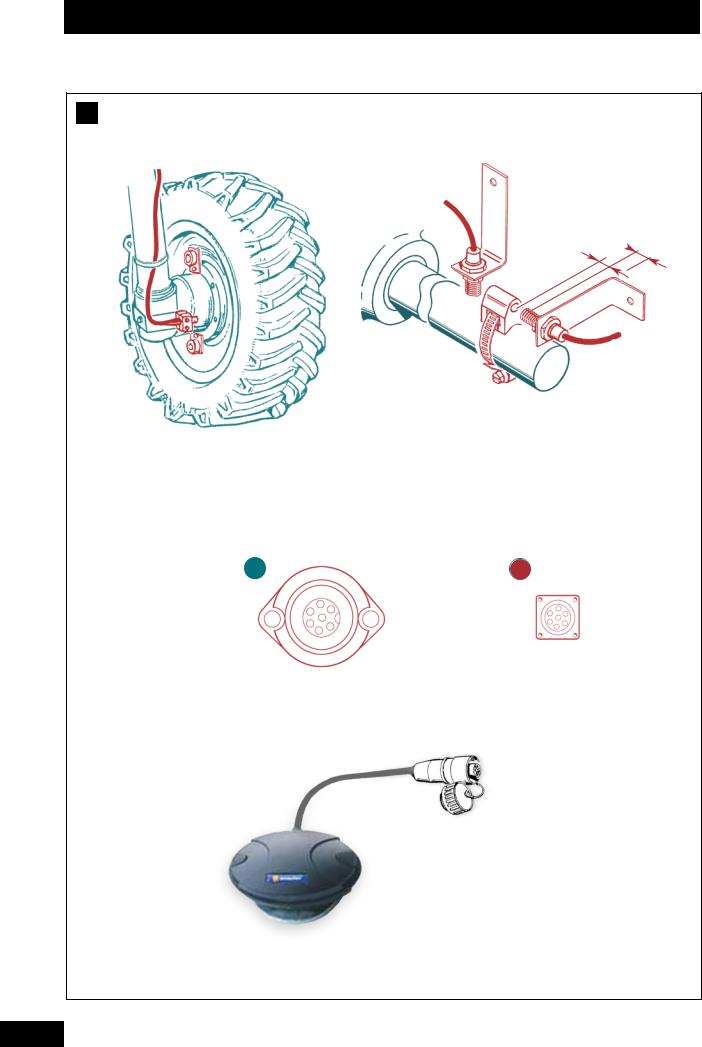
C |
Mise en place du capteur de vitesse |
b) Par l’arbre de transmission du pont avant |
|
|
Pour le montage du capteur, suivre les instructions. |
L’information vitesse peut être réalisée soit :
→Par la roue du tracteur,
→Par l’arbre de transmission du pont avant d’un tracteur 4x4,
→Par information radar pour les tracteurs prééquipés et compatibles.
→Par antenne GPS.
a)Par la roue du tracteur
Pour un montage sur roue de grand diamètre, favoriser l’adaptation avec plusieurs aimants par souci de précision.
-Prévoir un minimum de 8 aimants par roue arrière du tracteur.
REMARQUE :
Si la distance entre 2 aimants est ≤ à 15cm, il faut alterner la polarité des aimants Nord/Sud sur la circonférence.
Ce montage est probablement un des plus précis car l’arbre a une forte démultiplication par rapport à la vitesse d’avancement.
c) Par information radar
L’adaptation est possible seulement s’il y a une prise radar en cabine 1 2 .
Voir information complémentaire avec votre revendeur tracteur.
EXEMPLE :
Fendt, John deere, CASE iH
Massey-fergusson (Datatronic 1).
d)Capteur de vitesse par GPS
- Raccorder le capteur à la prise du boîtier prévue à cet effet.
GB
C |
Fitting the speed sensor |
b) Front axle drive shaft |
|
|
Follow instructions for mounting the sensor. |
The speed data can come from either:
→The tractor’s wheels,
→The front axle drive shaft of a 4x4 tractor,
→Pre-installed radar on compatible tractors.
→By GPS aerial.
a)Tractor wheel
For fitting to large diameter wheels, it is preferable to use several magnets for greater accuracy.
- Use at least 8 magnets per tractor wheel (rear).
NOTE:
If the distance between two magnets is <15cm, it is necessary to alternate North/South magnet polarity around the circumference.
This mounting option is probably the most accurate because of the high reduction ratio of the shaft in relation to the forward speed.
c) Radar information
Adaptation is only possible if there is a radar connection in the cab 1 2 .
For additional information see your tractor dealer.
EXAMPLE:
Fendt, John deere, CASE iH
Massey-fergusson (Datatronic 1).
d)GPS rate sensor
-Connect the sensor to the plug connection provided on the unit.
DE
CAnbringen des Geschwindigkeitssensors
Die Information über die Geschwindigkeit kann auf mehrere Arten ermittelt werden:
→Über das Schlepperrad,
→Über die Antriebswelle des Vorderradantriebs eines Allrad-Schleppers,
→Über Radarinformation für die schon ausgerüsteten und kompatiblen Schlepper.
→Über GPS-Antenne.
a) Über das Schlepperrad
Bei Montage auf ein Rad mit großem Durchmesser sollten aus Gründen der Präzision mehrer Magnete verwendet werden.
-Pro Schlepperhinterrad mindestens 8 Magnete vorsehen.
ANMERKUNG:
Wenn der Abstand zwischen zwei Magneten weniger als oder genau 15 cm beträgt, müssen die Magnete so auf dem Umfang angebracht sein, dass sich die Polarität abwechselt (Nord/Süd).
b) Über die Antriebswelle des Vorderradantriebs
Für den Einbau des Sensors die Anweisungen befolgen.
Diese Installierung ist wahrscheinlich die genaueste, da die Welle eine starke Untersetzung im Verhältnis zur Fahr geschwindigkeit hat.
c) Über Radarinformation
Die Anpassung ist nur möglich, wenn ein Radarsteckverbinder in der Schlepperkabine 1 2 vorhanden ist. Für ergänzende Auskünfte wenden Sie sich an Ihren Schlepperfachhändler.
ZUM BEISPIEL:
Fendt, John deere, CASE iH
Massey-fergusson (Datatronic 1).
d)Geschwindigkeitsmesser über GPS
-Geschwindigkeitsmesser an die dazu am Elektronikgerät vorgesehene Steckverbindung anschließen.
1
1
11

Présentation / Presentation / Beschreibung
D
10 8 9 2
1 |
4 |
3 |
5 |
7 |
6 |
12

Présentation / Presentation / Beschreibung
FR
DBoîtier de commande VISION
•1 • Mise sous tension
•2 • Pavé numérique et alphabétique
•3 • Ecran multifonction
•4 • Touches des fonctions
•5 • Touche menu paramétrage usine
et diagnostique revendeur
• 6 • Touche de “confirmation” ou “entrée” d’un paramétrage
•7 • Touche “retour”
•8 • Touche “menu épandage” : utilisée en cours
d’épandage
• 9 • Touche “menu information” : utilisée en consultation
• 10 • Touche “menu réglage” : utilisée en début d’épandage
Le boîtier fonctionne sous la forme d’un menu défilant.
Prendre le temps de lire les informations.
GB
DVISION control unit
•1 • Power on switch
•2 • Alpha-numeric pad
•3 • Multifunction screen
•4 • Function keys
•5 • Factory settings and diagnostic key
•6 • Settings confirmation or ENTER key
•7 • Return key
•8 • “Spreading menu” key: to be used during
spreading operations
•9 • “Info menu ” key: used for diagnosis or monitoring
•10 • “Settings menu” key: for use when starting
spreading
The unit operates with scroll-down menus.
Take time to read all the information.
DE
DBordcomputer VISION
•1 • Unterspannungsetzen
•2 • Zahlentastenfeld
•3 • Multifunktioneller Bildschirm
•4 • Funktionstasten
•5 • Taste des Menüs Werksparametrierung und
Diagnose des Verkäufers
• 6 • „Bestätigungs“-Taste oder „Eingabe“ einer Parametrierung
•7 • „Zurück“-Taste
•8 • Taste „Streu-Menü“: wird beim Streuen
benutzt
• 9 • Taste „Informations-Menü“: wird bei Anfragen benutzt
• 10 • Taste „Einstellungs-Menü“: wird zu Beginn des Streuens benutzt
Das Gerät funktioniert mit ablaufenden Menüs.
Nehmen Sie sich die Zeit, die angezeigten Informationen zu lesen.
1
1
13

Présentation / Presentation / Beschreibung
E
10 |
15 |
14 |
13 |
1 |
|
|
|
2 |
|
|
|
3 |
|
|
12 |
4 |
|
|
11 |
|
|
10 |
|
|
|
|
5 6 7 8 9
14

Présentation / Presentation / Beschreibung
FR
EPrésentation des fonctions
a)Menu épandage
Le menu épandage est utilisé en cours de travail. Vous disposez des principales informations de contrôle.
• |
1 • |
Heure |
• |
2 • |
Vitesse d’avancement. Elle peut être |
|
|
légèrement différente du compteur tracteur. |
•3 • Quantité d’épandage.
•4 • Indicateur de positionnement des vérins
électriques de contrôle des débits.
•5 • Touche modulation + 10%
•6 • Touche modulation - 10%
• |
7 • |
Retour à la dose hectare de référence après une |
|
|
modulation. |
• |
8 • |
Touche commande TRIBOR D et de sélection |
|
|
modulation “droite” ou “gauche” |
•9 • Touche test de débit
•10 • Indicateur d’ouverture/fermeture des trappes
hydrauliques
• |
11 • |
Poids dans la trémie (Réel) |
• |
12 • |
Dose hectare souhaitée. |
•13 • Alarme
•14 • Information mode de correction :
dynamique ou statique
• 15 • Nom de l’engrais
GB
EFunctions
a)Spreading menu
The spreading menu is used during spreading operations. It provides the main control data:
• |
1 • |
Time |
• |
2 • |
Working speed. It may be slightly different |
|
|
from that on the tractor speedometer. |
•3 • Spreading amount.
•4 • Position indicator of the flow-rate control
electrical rams.
•5 • +10% modulation key
•6 • -10% modulation key
• |
7 • |
Restoration of the reference dose/hectare |
|
|
following modulation. |
• |
8 • |
Tribord control key and “right” or “left” |
|
|
modulation select key |
• |
9 • |
Output flow rate test key |
• |
10 • |
Hydraulic shutter close/open indicator |
• |
11 • |
Weight in the hopper (effective) |
• |
12 • |
Dose per hectare targetted |
• |
13 • |
Alarm |
• |
14 • |
Correction mode info: Static or Dynamic |
• |
15 • |
Name of fertiliser |
DE
EFunktionsbeschreibungen
a)Streu-Menü
Das Streu-Menü wird während der Arbeit benutzt. Sie verfügen über die wesentlichsten Informationen zur Kontrolle.
•1 • Uhrzeit
•2 • Fahrgeschwindigkeit. Diese kann geringfügig
von der des Geschwindigkeitsmessers des Schleppers abweichen.
•3 • Streumenge.
•4 • Stellungsanzeiger der Elektro-Zylinder zur
Streumengenkontrolle.
•5 • Modulationstaste + 10%
•6 • Modulationstaste - 10%
• |
7 • |
Zurück zur Referenzstreumenge/ha nach einer |
|
|
Modulation. |
• |
8 • |
Steuertaste für Tribord und für die Auswahl |
|
|
zwischen "rechts" und "links". |
• |
9 • |
Taste Streumengentest |
• 10 • |
Anzeige Öffnung/ Schließung der |
|
|
|
Hydraulikschieber |
• |
11 • |
Gewichtskontrolle des Düngers im Behälter |
|
|
(Reell) |
• 12 • |
Gewünschte Streumenge/ ha |
|
•13 • Alarm
•14 • Information über den Korrektur-Modus:
dynamisch oder statisch
• 15 • Düngerbezeichnung
1
1
15

Présentation / Presentation / Beschreibung
E
1

2

3

4 5 6 7 8
16

Présentation / Presentation / Beschreibung
FR
E
b)Menu informations
Le menu information est utilisé en consultation pour connaître les performances du chantier d’épandage.
•1 • Nombre de tonnes épandues. (Théorique)
•2 • Surface en hectare épandue. (Réelle)
•3 • Indicateur du nombre d’hectares ou nombre
de mètres restant à épandre.
• 4 • Touche de sélection en information partielle pour la parcelle ou totale pour le chantier d’épandage.
• 6 • Touche de sélectionde la fonction enregistrement
des données et mode DGPS.
•7 • Touche d’information des alarmes actives.
•8 • Touche de remise à zéro des compteurs hectare
et tonnage.
• 5 • Touche de sélection du nombre d’hectares ou du nombre de mètres restantà épandre avec la quantité restant en trémie.
GB
E
b)Info menu
The info menu is used to monitor spreading data and performance.
•1 • Number of tonnes spread. (theoretical)
•2 • Area spread (in hectares). (effective)
•3 • Area remaining to be spread (in hectares or in
square metres).
• 4 • Selection key for partial (plot) or overall (site) spreading data.
• 5 • Selection key for the number of hectares or metres remaining to be spread and the amount left in the hopper.
• 6 • Selection key for data saving or GPS functions.
•7 • Active alarm info key.
•8 • Area and tonnage counter reset key.
DE
E
b)Informations-Menü
Das Informations-Menü wird benutzt, um die geleistete Streu arbeit in Erfahrung zu bringen.
•1 • Anzahl der gestreuten Tonnen. (Theoretisch)
•2 • Bestreute Fläche in Hektar. (Reell)
•3 • Anzeige der noch zu bestreuenden Fläche in
Hektar oder Meter.
• 4 • Wahltaste: Teilinformation über die Parzelle oder Gesamt information über den Streueinsatz.
• 5 • Wahltaste: mit der im Düngerbehälter verbleibenden Rest menge noch zu bestreuende Fläche in Hektar oder Meter.
• 6 • Wahltaste: Datenspeicherung oder DGPSModus.
•7 • Informationstaste: aktivierte Alarmfunktionen.
•8 • Taste zur Nullstellung von Hektarund
Mengenzähler.
1
1
17

Présentation / Presentation / Beschreibung
E
1 

2 3 4 5 6
18
 Loading...