


293 Wright Street, Delavan, WI 53115
OWNER’S MANUAL
Shallow Well Jet Pumps
NOTICE D’UTILISATION
Pompes à éjecteur pour puits peu profonds
MANUAL DEL PROPIETARIO
Bombas tipo “Jet” para pozos poco profundos
SN Series / Série SN / Serie SN
HN Series / Série HN / Serie HN
Installation/Operation/Parts |
Installation/Fonctionnement/Pièces |
Instalación/Operación/Piezas |
For further operating, installation, |
Pour plus de renseignements |
or maintenance assistance: |
concernant l’utilisation, |
|
l’installation ou l’entretien, |
Para mayor información sobre el functionamiento, instalación o mantenimiento de la bomba:
Call 1-262-728-9181 |
composer le 1 (262) 728-9181 |
llame al 1-262-728-9181 |
||
English . . . . . . . . . . . . . . . |
Pages 2-14 Français . . . . . . . . . . . . . |
Pages 15-27 |
Español . . . . . . . . . . . . . |
Paginas 28-40 |
© 2008 |
S376 (Rev. 5/5/09) |

Safety |
2 |
READ AND FOLLOW
SAFETY INSTRUCTIONS!
This is the safety alert symbol. When you see this
 symbol on your pump or in this manual, look for one of the following signal words and be alert to the potential for personal injury:


 warns about hazards that will cause serious personal injury, death or major property damage if ignored.


 warns about hazards that can cause serious personal injury, death or major property damage if ignored.


 warns about hazards that will or can cause minor personal injury or property damage if ignored.
The label NOTICE indicates special instructions which are important but not related to hazards.
Carefully read and follow all safety instructions in this manual and on pump.
Keep safety labels in good condition.
Replace missing or damaged safety labels.
 WARNING
Hazardous voltage. Can shock, burn, or cause death.
Ground pump before connecting to power supply. Disconnect power before working on pump, motor or tank.
Wire motor for correct voltage. See “Electrical”
section of this manual and motor nameplate.
Ground motor before connecting to power
supply.
Meet National Electrical  Code, Canadian Electrical Code, and local codes for
all wiring.
Follow wiring instructions in this manual
when connecting motor to power lines.
ELECTRICAL SAFETY


 Capacitor voltage may be hazardous. To discharge motor capacitor, hold insulated handle screwdriver BY THE HANDLE and short capacitor terminals together.
Do not touch metal screwdriver blade or capacitor terminals. If in doubt, consult a qualified electrician.
GENERAL SAFETY


 Do not touch an operating motor. Modern motors are designed to operate at high temperatures. To avoid burns when servicing pump, allow it to cool for 20 minutes after shut-down before handling.
Do not allow pump or any system component to freeze. To do so will void warranty.
Pump water only with this pump.
Periodically inspect pump and system components.
Wear safety glasses at all times when working on pumps.
Keep work area clean, uncluttered and properly lighted; store properly all unused tools and equipment.
Keep visitors at a safe distance from the work areas.


 Pump body may explode if used as a booster pump unless relief valve capable of passing full pump flow at 75 psi is installed.
WARNING
Hazardous pressure! Install pressure relief valve in discharge pipe.
Release all pressure on system before working on any component.

Table of Contents |
3 |
|
Page |
General Safety ..................................................................................................... |
2 |
Warranty .............................................................................................................. |
3 |
Installation (Well Pumps) ................................................................................. |
4, 5 |
Connecting Discharge Piping............................................................................... |
6 |
Pressure Booster System....................................................................................... |
7 |
Electrical .......................................................................................................... |
8, 9 |
Preparing To Start The Pump.............................................................................. |
10 |
Repair Parts .................................................................................................. |
11-13 |
Troubleshooting.................................................................................................. |
14 |
LIMITED WARRANTY
STA-RITE warrants to the original consumer purchaser (“Purchaser” or “You”) of the products listed below, that they will be free from defects in material and workmanship for the Warranty Period shown below.
Product |
Warranty Period |
Water Systems Products — jet pumps, |
whichever occurs first: |
small centrifugal pumps, submersible pumps |
12 months from date of original installation, or |
and related accessories |
18 months from date of manufacture |
Pro-SourceTM Composite Tanks |
5 years from date of original installation |
Pro-SourceTM Steel Pressure Tanks |
5 years from date of original installation |
Pro-SourceTM Epoxy-Lined Tanks |
3 years from date of original installation |
Sump/Sewage/Effluent Products |
12 months from date of original installation, or |
|
18 months from date of manufacture |
Our warranty will not apply to any product that, in our sole judgement, has been subject to negligence, misapplication, improper installation, or improper maintenance. Without limiting the foregoing, operating a three phase motor with single phase power through a phase converter will void the warranty. Note also that three phase motors must be protected by three-leg, ambient compensated, extra-quick trip overload relays of the recommended size or the warranty is void.
Your only remedy, and STA-RITE’s only duty, is that STA-RITE repair or replace defective products (at STA-RITE’s choice). You must pay all labor and shipping charges associated with this warranty and must request warranty service through the installing dealer as soon as a problem is discovered. No request for service will be accepted if received after the Warranty Period has expired. This warranty is not transferable.
STA-RITE SHALL NOT BE LIABLE FOR ANY CONSEQUENTIAL, INCIDENTAL, OR CONTINGENT DAMAGES WHATSOEVER.
THE FOREGOING WARRANTIES ARE EXCLUSIVE AND IN LIEU OF ALL OTHER EXPRESS AND IMPLIED WARRANTIES, INCLUDING BUT NOT LIMITED TO THE IMPLIED WARRANTIES OF MERCHANTABILITY AND FITNESS FOR A PARTICULAR PURPOSE. THE FOREGOING WARRANTIES SHALL NOT EXTEND BEYOND THE DURATION EXPRESSLY PROVIDED HEREIN.
Some states do not allow the exclusion or limitation of incidental or consequential damages or limitations on the duration of an implied warranty, so the above limitations or exclusions may not apply to You. This warranty gives You specific legal rights and You may also have other rights which vary from state to state.
This warranty supersedes and replaces all previous warranty publications.
STA-RITE INDUSTRIES
293 Wright St., Delavan, WI 53115
Installation |
4 |
REPLACING AN OLD PUMP


 Hazardous voltage. Disconnect power to pump before working on pump or motor.
1.Drain and remove the old pump. Check the old pipe for scale, lime, rust, etc., and replace it if necessary.
2.Install the pump in the system. Make sure that all pipe joints in the suction pipe are air-tight as well as water tight. If the suction pipe can suck air, the pump will not be able to pull water from the well.
3.Adjust the pump mounting height so that the plumbing connections do not put a strain on the pump body. Support the pipe so that the pump body does not take the weight of piping or fittings.
You have just completed the well plumbing for your new shallow well jet pump. Please go to Page 6 for discharge pipe and tank connections.
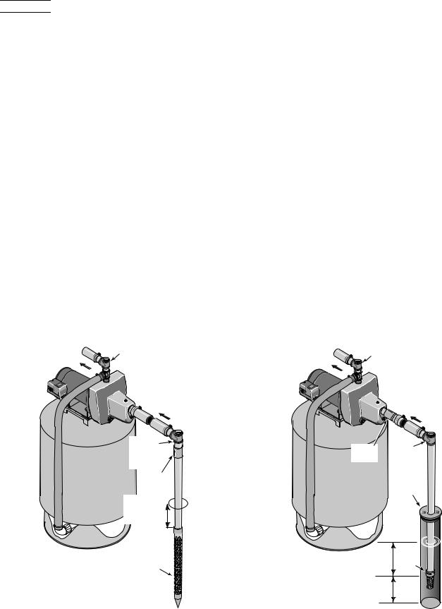
WELL POINT (DRIVEN POINT) INSTALLATION (FIGURE 1)
1.Drive the well, using “drive couplings” and a “drive cap”. “Drive fittings” are threaded all the way through and allow the pipe ends to butt against each other so that the driving force of the maul is carried by the pipe and not by the threads. The ordinary fittings found in hardware stores are not threaded all the way through the fitting and can collapse under impact. “Drive fittings” are also smoother than standard plumbing fittings, making ground penetration easier.
To Household |
Pump Priming |
Water System |
Tee and Plug |
|
Suction Pipe |
|
From Well |
Priming |
Tee and |
Plug |
Check |
Valve |
Drive point 
 below water
level
Drive 


Coupling
2346 0396 |
Drive |
|
|
|
Point |
Not
to
Scale
2.Mount the pump as close to the well as possible
3.Use the fewest possible fittings (especially elbows) when connecting the pipe from the well point to the pump suction port. The suction pipe should be at least as large as the suction port on the pump (include a check valve if your pump is not equipped with one – see Figure 1). Support the pipe so that there are no dips or sags in the pipe, so it doesn’t strain the pump body, and so that it slopes slightly upward from the well to the pump (high spots can cause air pockets which can air lock the pump). Seal the suction pipe joints with teflon tape or a teflon based pipe joint compound. Joints must be airand water-tight. If the suction pipe can suck air, the pump cannot pull water from the well. If one well point does not supply enough water, consider connecting two or three well points to one suction pipe.
You have just completed the suction piping for your new shallow well jet pump. Please go to Page 6 for discharge pipe and tank connections.
CASED WELL INSTALLATION, 2" OR LARGER CASING (FIGURE 2)
1.Mount the pump as close to the well as possible.
2.Assemble the foot valve, strainer, and well pipe (see Figure 2). Make sure that the foot valve works freely.
3.Lower the pipe into the well until the strainer is five feet above the bottom of the well. It should also be at least 10 feet below the well’s water level while the pump is running in order to prevent the pump from sucking air. Install a sanitary well seal.
To Household |
Pump Priming |
||
Water System |
Tee and Plug |
||
|
|
Suction Pipe |
|
|
|
From Well |
|
Check |
|
Priming |
|
Valve |
|
Tee and |
|
|
|
Plug |
|
|
|
Sanitary |
|
|
|
Well Seal |
|
|
|
Well |
|
|
|
Casing |
|
2347 0396 |
10' |
Foot |
|
Not |
|||
Min. |
Valve |
||
to |
|
|
|
Scale 5–10' |
|
||
Figure 1: Driven Point Installation |
Figure 2: Cased Well Installation |

Installation |
5 |
4.Install a priming tee, priming plug, and suction pipe to the pump (see Figure 2). Connect the pipe from the well to the pump suction port, using the fewest possible fittings – especially elbows – as fittings increase friction in the pipe (however, include a foot valve – see Figure 2). The suction pipe should be at least as large as the suction port on the pump. Use teflon tape or a teflon-based pipe joint compound on threaded pipe joints. Support the pipe so that there are no dips or sags in the pipe, so it doesn’t strain the pump body, and so that it slopes slightly upward from the well to the pump (high spots can cause air pockets which can air lock the pump). Seal the suction pipe joints with teflon tape or a teflon based pipe joint compound. Joints must be airand watertight. If the suction pipe can suck air, the pump cannot pull water from the well.
You have just completed the suction piping for your new shallow well jet pump. Please go to Page 6 for discharge pipe and tank connections.
INSTALLATION FOR SURFACE WATER (FIGURE 3)
1.The pump should be installed as close to the water as possible, with the fewest possible fittings (especially elbows) in the suction pipe. The suction pipe should be at least as large as the suction port on the pump.
To Household |
Pump Priming |
Water System |
Tee and Plug |
|
Suction Pipe |
|
From Well |
2.Assemble a foot valve and suction pipe (see Figure 3). Make sure that the foot valve works freely. Use teflon tape or a teflon-based pipe joint compound on threaded pipe joints. Protect the foot valve assembly from fish, trash, etc, by installing a screen around it (see Figure 3).
3.Lower the pipe into the water until the strainer is five feet above the bottom. It should also be at least 10 feet below the water level in order to prevent the pump from sucking air.
4.Install a priming tee, priming plug, and suction pipe to the pump (see Figure 3). Support the pipe so that there are no dips or sags in the pipe, so it doesn’t strain the pump body, and so that it slopes slightly upward from the well to the pump (high spots can cause air pockets which can air lock the pump). Seal the suction pipe joints with teflon tape or a teflon based pipe joint compound. Joints must be airand water-tight. If the suction pipe can suck air, the pump cannot pull water from the well.
You have just completed the plumbing for your new shallow well jet pump. Please go to Page 6 for discharge pipe and tank connections.
Not
to
Scale
Check
Valve Priming
Tee and
Plug
2348 0396
10' |
Foot |
Min. |
Valve |
|
|
5–10'
Screen 
Figure 3: Surface Water Installation

Discharge Pipe and Pressure Tank Connections |
6 |
PRE-CHARGE TANK CONNECTION (FIGURE 4)
1.Install two tees in the pump discharge port (see Figure 4). The pipe size must be at least as large as the discharge port.
2.Run a pipe or reinforced hose from one arm of the first tee to the port on the pre-charged tank.
3.Connect the other end of the discharge tee to your plumbing system.
4.Check the pre-charge of air in the tank with an ordinary tire gauge. The pre-charge should be 2 PSI less than the cut-in setting of the pump’s pressure switch. The pre-charge is measured when there is no water pressure in the tank. Your new pump has a 30/50 PSI switch, so adjust the tank pre-charge pressure to
28 PSI.
Congratulations! You have just completed the tank connection for your jet pump.
Please go to Page 8 for electrical hookup.
To Household |
Pump Priming |
Water System |
Tee and Plug |
|
From Well |
Pressure |
|
Switch |
|
|
Check |
|
Valve |
2349 0396
Figure 4: Pre-charged Tank Connections
STANDARD TANK CONNECTION (FIGURE 5)
1.Install one tee in the pump discharge port (see Figure 5).
2.Run a pipe from the pump discharge port to the inlet port of your tank. The pipe size must be at least as large as the discharge port.
3.Remove the 1/8" NPT pipe plug from the pump Air Volume Control (AVC) port (see Figure 5). Run tubing from the pump’s AVC port (see Figure 5) to the port on the AVC mounted on the tank. See instructions provided with tank and AVC for details. AVC port location will vary, depending on your pump model (see exploded view, Page 11).
Congratulations! You have just completed the tank connection for your jet pump.
Please go to Page 8 for electrical hookup.
To Household
Water System
|
Air Volume |
|
|
Control |
|
Pump |
Air Volume |
|
Priming Tee |
||
Control Tube |
||
and Plug |
||
|
2350 0396
From
Well
Pressure
Switch Check
Valve
Figure 5: Standard Tank Connections
Sealing Pipe Joints
Use only Teflon tape or Teflon based joint compounds for making all threaded connections to the pump itself. Do not use pipe joint compounds on plastic pumps: they can react with the plastic in pump components. Make sure that all pipe joints in the suction pipe are air tight as well as water tight. If the suction pipe can suck air, the pump will not be able to pull water from the well.

Typical Pressure Booster System |
7 |
|
Pressure |
Gate Valve |
|
Water Out |
Gauge |
and Union |
|
for Service |
|||
|
|||
to Household |
Access |
||
Low Pressure |
|
||
Cutoff Switch Tee |
Check |
||
Pressure |
Relief |
Valves |
|
Switch |
Valve |
|
|
City Water
Flow In
Union and Gate Valve for Service Access
2882 0198
Figure 6: Model SNCP42
Gate Valve and Union for Service Access
Pressure
Switch
Pressure
Low Gauge 
Pressure
Cutoff 
Switch
Tee
Water Out to
Household Relief
Valve
Figure 7: Model SNCP15
Gate Valve and Union for Service Access
City Water
Flow In
|
Check |
2887 0198 |
Valves |
User Supplied Components:
Low Pressure Cutoff |
Pressure Gauge (1) |
Switch (1) |
Unions (3) |
|
|
Check Valves (2) |
Elbow (1) |
|
|
Gate Valves (2) |
Tees (2) |
|
|
Relief Valve (1) |
Piping |
|
INSTALLATION


 Hazardous pressure. Install a relief valve as shown capable of passing entire pump flow at 75 PSI. Pump body may explode if internal pressure exceeds 75 PSI.


 Never run pump against closed discharge. To do so can boil water inside pump, causing hazardous pressure in unit, risk of explosion and possibly scalding persons handling pump.
NOTICE: The incoming flow rate must equal or exceed the minimum pump flow requirement of 6 Gallons per Minute or the pump will fail. As a rule, the pump will not increase the flow rate in the system.
A low pressure safety cutoff switch is recommended to shut off power to the pump in case of low discharge pressure caused by plugged nozzle, interruption to the incoming water supply, etc.
For pressure switch adjustment instructions, refer to the label inside the cover of the pressure switch.
The system can be located indoors or outdoors. Make sure that the site is level, solid, well drained, and protected from the weather and from freezing.
1.Turn off city water to house.
2.Install pipe as shown (Figures 6 and 7). Be sure to include unions and stop valves so that pressure booster unit can be removed for service without interrupting household water supply. A spring loaded check valve ahead of the booster system and a low pressure cutoff switch after it are recommended (You may wish to replace the standard pressure switch with a pressure switch that includes a low pressure cutoff).
3.Use teflon tape on all piping joints to prevent leaks.
Please go to Pages 8 and 9 for electrical hookup.
Table I: Pressure Switch Setting for Booster System
If Minimum |
Use |
Set |
|
Incoming System |
Pressure Switch |
Tank |
|
Pressure Is: |
Rated At: |
Precharge at: |
|
Below 20 PSI |
20/40; set cut-in |
18 PSI |
|
to 20 PSI |
|||
|
|
||
20-30 PSI |
30/50; set cut-in |
28 PSI |
|
to 30 PSI |
|||
|
|
||
30-40 PSI |
40/60; set cut-in |
38 PSI |
|
to 40 PSI |
|||
|
|
||
|
|
|

Electrical |
8 |
 Disconnect power before working on pump, motor, pressure switch, or wiring.
MOTOR SWITCH SETTINGS
Dual-voltage motors (motors that can operate at either 115 or 230 volts), are set at the factory to 230 volts. Do not change motor voltage setting if line voltage is 230 volts, or if you have a single voltage motor.
NOTE: Never wire a 115 volt motor to a 230 volt line.
NOTE: Wire TEFC motors according to wiring diagram in junction box on motor. Be sure motor is connected for correct line voltage.
NOTE: Wire 3-Phase motors according to wiring diagram on motor. Be sure motor is connected for correct line voltage.
Remove Motor End Cover
If you have a dual-voltage motor, and will connect it to 115 volts, follow the procedure below.
You will need to remove the motor end cover to change the voltage setting.
End Cover Screws
Motor 
End Cover
Figure 8: Removing End Cover
Your motor terminal board (located under the motor end cover) should look like the one below.
Dial Type Voltage Selector
To change to 115 volts:
1.Make sure power is off.
2.Turn the dial counter-clockwise until 115 shows in the dial window.
Power Supply Connections
Voltage
Change
Dial
Pressure Switch
Ground Wire Connection
Figure 9:Voltage Adjustment Dial
3.Attach the power lead wires to the power lead terminals. Make sure the wires are secure.
4.Attach the ground wire to the green ground screw.
5.Reinstall the Motor end cover.
Go to Wiring Connections below.


 Hazardous voltage. Can shock, burn, or kill. Connect ground wire before connecting power supply wires. Use the wire size (including the ground wire) specified in the wiring chart. If possible, connect the pump to a separate branch circuit with no other appliances on it.


 Explosion hazard. Do not ground to a gas supply line.

Electrical |
9 |
WIRING CONNECTIONS


 Fire hazard. Incorrect voltage can cause a fire or seriously damage the motor and voids the warranty. The supply voltage must be within ±10% of the motor nameplate voltage.
NOTICE: Dual-voltage motors are factory wired for 230 volts. If necessary, reconnect the motor for 115 volts, as shown. Do not alter the wiring in single voltage motors.
Install, ground, wire, and maintain your pump in compliance with the United States National Electrical Code (NEC) or the Canadian Electrical Code (CEC), as applicable, and with all local codes and ordinances that apply. Consult your local building inspector for code information.
2.There must be a solid metal connection between the pressure switch and the motor for motor grounding protection. If the pressure switch is not connected to the motor, connect the green ground screw in the switch to the green ground screw under the motor end cover. Use a solid copper wire at least as large as the power supply wires.
3.Connect the ground wire to a grounded lead in a service panel, to a metal underground water pipe, to a metal well casing at least ten feet (3M) long, or to a ground electrode provided by the power company or the hydro authority.
4.Connect the power supply wires to the pressure switch as shown in Figure 9.
Connection Procedure:
1.Connect the ground wire first as shown in Figure 9. The ground wire must be a solid copper wire at least as large as the power supply wires.
WIRING CHART – RECOMMENDED WIRE AND FUSE SIZES
|
|
|
|
DISTANCE IN FEET(METERS) FROM MOTOR TO SUPPLY |
|
||||||
|
|
|
|
|
|
|
|
|
|
|
|
|
|
|
|
0 - 100 |
101 |
- 200 |
201 |
- 300 |
301 - 400 |
401 |
- 500 |
|
|
Max. Load |
Branch Fuse |
(0 - 30) |
(31 |
- 61) |
(62 |
- 91) |
(92 - 122) |
(123 |
- 152) |
|
|
|
|
|
|
|
|
|
|
||
Motor HP |
Volts |
Amp |
Rating Amp |
|
|
AWG WIRE SIZE (mm2) |
|
|
|||
1/2 |
115/230 |
8.8/4.4 |
15/15 |
14/14 (2/2) |
12/14 (3/2) |
10/14 (5.5/2) |
8/14 (8.4/2) |
8/12 (8.4/3) |
|||
3/4 |
115/230 |
12.2/6.1 |
20/15 |
12/14 (3/2) |
10/14 (5.5/2) |
8/14 (8.4/2) |
6/12 (14/3) |
6/12 (14/3) |
|||
1 |
115/230 |
14.8/7.4 |
20/15 |
12/14 (3/2) |
8/14 (8.4/2) |
6/14 (14/2) |
6/12 (14/3) |
4/10 (21/5.5) |
|||
1-1/2 |
115/230 |
19.9/10.0 |
25/15 |
10/14 (5.5/2) |
8/14 (8.4/2) |
6/12 (14/3) |
4/10 (21/5.5) |
4/10 (21/5.5) |
|||

Preparing to Start the Pump |
10 |
PREPARING TO START THE PUMP


 Never run pump dry. Running pump without water may cause pump to overheat, damaging seal and possibly causing burns to persons handling pump. Fill pump with water before starting.


 Never run pump against closed discharge. To do so can boil water inside pump, causing hazardous pressure in unit, risk of explosion and possibly scalding persons handling pump.
1.Remove the priming plug from the priming tee and fill the pump. Fill all piping between the pump and the well and make sure that all piping in the well is full. If you have also installed a priming tee in the suction piping, remove the plug from the tee and fill the suction piping.
2.Replace all fill plugs.
3.Power on! Start the pump. If you don’t have water after 2 or 3 minutes, stop the pump and remove the fill plugs. Refill the pump and piping. You may have to repeat this several times in order to get all the trapped air out of the piping. A pump lifting water 25’ may take as long as 15 minutes to prime.
4.After the pump has built up pressure in the system and shut off, check the pressure switch operation by opening a faucet or two and running enough water out to bleed off pressure until the pump starts. The pump should start when pressure drops to 30 PSI and stop when pressure reaches 50 PSI. Run the pump through one or two complete cycles to verify correct operation. This will also help clean the system of dirt and scale dislodged during installation.
NOZZLE CLEAN OUT (LOW PRESSURE)
Use an icepick or brad awl to clean out the nozzle – 3/16" maximum diameter (see Figure 11). Be sure you DO NOT enlarge the hole in the nozzle. Use teflon tape on plug when reassembling to seal it.
1465 0497
Figure 11: Use Icepick or Brad Awl to Clean Out Nozzle
Congratulations on a successful installation.
If you were unsuccessful, please refer to the Troubleshooting section (Page 14).
Fill pump and piping through priming tee.
2351 0396
Figure 10: Prime the Pump
Repair Parts |
11 |
|
|
|
1 |
|
|
|
2 |
|
|
20 |
3 |
|
19 |
4 |
|
|
|
||
18 |
|
5 |
|
|
|
||
|
|
|
6
7
8
9
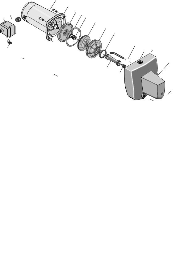
Exploded View
SN Series - 1/2 HP
17 |
|
|
|
|
10 |
12 |
|
16 |
|
|
|
|
|
|
|
15 |
|
|
|
|
|
|
|
|
|
|
|
|
|
|
12 (AVC Port) |
|
|
|
|
11B |
|
|
|
|
|
13 |
|
11A |
|
|
|
|
|
|
|
|
|
|
|
|
|
|
|
|
|
|
12 |
|
|
|
|
|
|
|
12 |
|
|
REPAIR PARTS LIST: SN Series, 1/2 HP |
|
|
|||
|
|
|
|
Model and Horsepower |
|||
Key |
|
Part |
No. |
SNC-L |
SNC-HF25L |
|
SNC-5L |
No. |
|
Description |
Used |
1/2 HP |
1/2 HP |
|
1/2 HP |
1 |
Motor |
1 |
J218-582APKG |
J218-582APKG |
J218-582APKG |
||
#§2 |
Water Slinger |
1 |
17351-0009 |
17351-0009 |
|
17351-0009 |
|
3 |
Seal Plate |
1 |
N3-1043P |
N3-1043P |
|
N3-1043P |
|
#§4 |
Seal Plate Gasket |
1 |
N20-35 |
N20-35 |
|
N20-35 |
|
#§5 |
Shaft Seal |
1 |
U109-6A |
U109-6A |
|
U109-6A |
|
#6 |
Impeller |
1 |
J105-40P |
J105-40P |
|
J105-40P |
|
#7 |
Diffuser |
1 |
L1-25P |
L1-25P |
|
L1-25P |
|
#§8 |
Diffuser Gasket |
1 |
N20-34 |
N20-34 |
|
N20-34 |
|
9 |
Quick Connect - 1/4" NPT |
1 |
U11-217P |
U11-217P |
|
— |
|
10 |
Pump Body - Assembly |
1 |
N176-43 |
N176-43A |
|
N176-43 |
|
11A |
|
Nozzle |
(1) |
N34P-17(#43) |
N34P-17(#43) |
|
N34P-17(#43) |
11B |
|
Venturi |
(1) |
N32P-66 |
N32P-67 |
|
N32P-66 |
12 |
Pipe Plug - 1/4" NPT Hex Hd. |
(4) |
U78-941ZPV(3) |
U78-941ZPV(3) |
U78-941ZPV |
||
13 |
Base |
1 |
J4-9 |
J4-9 |
|
J4-9 |
|
14 |
Hex Capscrew - 3/8" - 16 x 1-1/4" Lg. |
4 |
U30-75ZP |
U30-75ZP |
|
U30-75ZP |
|
14 |
Hex Capscrew - 3/8" - 16 x 1-1/2" Lg. |
2 |
— |
— |
|
— |
|
15 |
Rubber Pad |
1 |
C35-5 |
C35-5 |
|
C35-5 |
|
16 |
Tube 1/4" I.D. |
1 |
U37-676P |
U37-676P |
|
— |
|
17 |
Quick Connect Elbow - 1/4" NPT |
1 |
U11-218P |
U11-218P |
|
— |
|
18 |
Pressure Switch |
1 |
U217-1225 |
U217-1226 |
|
— |
|
19 |
Locknut - 1/2" |
1 |
U36-112ZP |
U36-112ZP |
|
— |
|
20 |
Connector |
1 |
L43-5C |
L43-5C |
|
— |
|
§ Included in Seal and Gasket Kit. |
|
|
|
|
|
||
# Included in Overhaul Kit. |
|
|
|
|
|
||
NOTE: Quantity is one unless otherwise noted ( ). |
|
|
|
|
|||
|
|
SERVICE KITS |
|
|
|
||
|
§ |
Seal and Gasket Kit |
|
PP1550 |
PP1550 |
|
PP1550 |
|
# |
Overhaul Kit |
|
PP1560 |
PP1560 |
|
PP1560 |
Repair Parts |
12 |
|
|
|
1 |
|
|
|
2 |
|
|
20 |
3 |
|
19 |
4 |
|
18 |
|
5 |
|
|
|
||
|
|
|
6
7
8
Exploded View SN Series - 3/4 thru 1-1/2 HP
|
9 |
|
17 |
10 |
12 |
|
16 |
|
|
15 |
|
12 (AVC Port)
11B
|
|
13 |
|
11A |
|
|
|
|
|
|
|
|
|
|
|
|
|
|
|
12 |
|
|
|
|
|
|
12 |
|
|
REPAIR PARTS LIST: SN Series, 3/4 thru 1-1/2 HP |
|
|||
|
|
|
|
Model and Horsepower |
||
Key |
|
Part |
No. |
SND-L |
SNE-L |
SNF-L |
No. |
|
Description |
Used |
3/4 HP |
1 HP |
1-1/2 HP |
1 |
Motor |
1 |
J218-590PKG |
J218-596PKG |
J218-601PKG |
|
#§2 |
Water Slinger |
1 |
17351-0009 |
17351-0009 |
17351-0009 |
|
3 |
Seal Plate |
1 |
N3-1043P |
L3-10 |
L3-10 |
|
#§4 |
Seal Plate Gasket |
1 |
N20-35 |
C20-21 |
C20-21 |
|
#§5 |
Shaft Seal |
1 |
U109-6A |
U109-6A |
U109-6A |
|
#6 |
Impeller |
1 |
J105-42P |
J105-8PAN |
J105-22PA |
|
#7 |
Diffuser |
1 |
L1-25P |
L1-23P |
L1-23P |
|
#§8 |
Diffuser Gasket |
1 |
N20-34 |
– |
– |
|
• |
Diffuser Screw |
3 |
– |
U30-489SS |
U30-489SS |
|
• |
Diffuser Star Washer |
3 |
– |
U43-21SS |
U43-21SS |
|
9 |
Quick Connect - 1/4" NPT |
1 |
U11-217P |
U11-217P |
U11-217P |
|
10 |
Pump Body - Assembly |
1 |
N176-43B |
N176-44 |
N176-44A |
|
11A |
|
Nozzle |
(1) |
N34P-21(#47) |
J34P-44(#54) |
J34P-44(#54) |
11B |
|
Venturi |
(1) |
N32P-75 |
N32P-64 |
N32P-65 |
12 |
Pipe Plug - 1/4" NPT Hex Hd. |
(4) |
U78-941ZPV(3) |
U78-941ZPV |
U78-941ZPV |
|
13 |
Base |
1 |
J4-9 |
J4-9C |
J4-9C |
|
14 |
Hex Capscrew - 3/8" - 16 x 1-1/4" Lg. |
4 |
U30-75ZP |
U30-75ZP(2) |
U30-75ZP(2) |
|
14 |
Hex Capscrew - 3/8" - 16 x 1-1/2" Lg. |
2 |
— |
U30-76ZP |
U30-76ZP |
|
15 |
Rubber Pad |
1 |
C35-5 |
C35-5 |
C35-5 |
|
16 |
Tube 1/4" I.D. |
1 |
U37-676P |
U37-672P |
U37-672P |
|
17 |
Quick Connect Elbow - 1/4" NPT |
1 |
U11-218P |
U11-218P |
U11-218P |
|
18 |
Pressure Switch |
1 |
U217-1225 |
U217-1225 |
U217-1225 |
|
19 |
Locknut - 1/2" |
1 |
U36-112ZP |
U36-112ZP |
U36-112ZP |
|
20 |
Connector |
1 |
L43-5C |
L43-5C |
L43-5C |
|
§ Included in Seal and Gasket Kit. |
|
|
|
|
||
# Included in Overhaul Kit. |
|
|
|
|
||
NOTE: Quantity is one unless otherwise noted ( ). |
|
|
|
|||
• Not illustrated. |
|
|
|
|
||
|
|
SERVICE KITS |
|
|
||
|
§ |
Seal and Gasket Kit |
|
PP1550 |
PP1553 |
PP1564 |
|
# |
Overhaul Kit |
|
PP1561 |
PP1563 |
PP1514 |
 Loading...