


IntelliFlo® VF
Variable Flow Pump
(Compatible with IntelliTouch® control system and IntelliComm® communication center)
Listed
Installation
and
User's Guide
IMPORTANT SAFETY INSTRUCTIONS
READ AND FOLLOW ALL INSTRUCTIONS
SAVE THESE INSTRUCTIONS
Technical Support
Sanford, North Carolina (8 A.M. to 5 P.M. ET)
Moorpark, California (8 A.M. to 5 P.M. PT)
Phone: (800) 831-7133
Fax: (800) 284-4151
Web sites: www.pentairpool.com and www.staritepool.com
Protected by U.S. Patents Pending
© 2009 Pentair Water Pool and Spa, Inc. All rights reserved
This document is subject to change without notice.
1620 Hawkins Ave., Sanford, NC 27330 • (919) 566-8000
10951 West Los Angeles Ave., Moorpark, CA 93021 • (805) 553-5000
Trademarks and disclaimers: IntelliFlo®, IntelliTouch®, EasyTouch®, SunTouch®, IntelliComm® and Pentair Water Pool and Spa® are trademarks and/or registered trademarks of Pentair Water Pool and Spa, Inc. and/or its affiliated companies in the United States and/or other counties.Teflon® is a registered trademark of E.I. Du Pont De Nemours and Company Corporation. Unless noted, names and brands of others that may be used in this document are not used to indicate an affiliation or endorsement between the proprietors of these names and brands and Pentair Water Pool and Spa, Inc. Those names and brands may be the trademarks or registered trademarks of those parties or others.
P/N 350075 Rev D - 7-14-09

i
Contents |
|
Important Safety Precautions ........................................................................................... |
iii |
Section 1: Introduction ...................................................................................................... |
1 |
IntelliFlo Overview................................................................................................................. |
1 |
IntelliFlo Features...................................................................................................... |
2 |
IntelliFlo Motor Assembly .......................................................................................... |
2 |
IntelliFlo Motor Features ............................................................................................ |
3 |
IntelliFlo Drive Assembly and Control Panel ............................................................. |
4 |
Operator Control Panel Features ............................................................................. |
4 |
Section 2: Operator Control Panel................................................................................... |
5 |
IntelliFlo Operator Control Panel ........................................................................................... |
5 |
Controls and LEDs ................................................................................................... |
5 |
Navigating the Menu Structure .............................................................................................. |
7 |
Section 3: Operating IntelliFlo .......................................................................................... |
9 |
Metering the System............................................................................................................. |
9 |
Manual Mode ........................................................................................................................ |
9 |
IntelliFlo Control Panel Menu ............................................................................................... |
11 |
Menu Structure .................................................................................................................... |
12 |
Pool Data Mode ....................................................................................................... |
13 |
Priming Mode ........................................................................................................... |
14 |
Priming Menu ........................................................................................................ |
14 |
Filter Mode ............................................................................................................... |
16 |
Filter Menu ............................................................................................................ |
16 |
Programming Cycles Per Day .............................................................................. |
17 |
Filter Cycle Settings.............................................................................................. |
18 |
Clean Filter Pressure Example ............................................................................. |
19 |
Alert Status ............................................................................................................ |
19 |
Using Filter mode with Features mode ................................................................. |
20 |
Filter Mode and Flow Control ................................................................................ |
21 |
Flow Control and Filter Mode ................................................................................ |
21 |
Time and Contrast Menu ......................................................................................... |
22 |
Setting System Time ............................................................................................ |
22 |
Setting the LCD Backlight Contrast ...................................................................... |
22 |
Features Mode ......................................................................................................... |
23 |
Features 1 & 2 ...................................................................................................... |
23 |
Features 3 -9 ........................................................................................................ |
23 |
M. O. Flo ............................................................................................................... |
23 |
Feature Settings ................................................................................................... |
24 |
How to set up the Feature 1 or 2 (Flow and Duration) mode ................................ |
25 |
Features 1 – 2 (Flow and Duration) ...................................................................... |
26 |
To run Feature 1 or 2 (Flow and Duration) ............................................................ |
26 |
Features 3 – 9 (Flow, Start/Stop Time) ................................................................. |
26 |
Enabling Features 3 – 9 ........................................................................................ |
26 |
Mo Flo (Modulation Output flow) ........................................................................... |
28 |
IntelliFlo VF Installation and User’s Guide
ii
Contents (Continued) |
|
External Control with IntelliComm Communication Center....................................... |
29 |
Setting up External Control using IntelliComm.......................................................... |
30 |
Controlling IntelliFlo with IntelliTouch ......................................................................... |
31 |
Connecting IntelliFlo to IntelliTouch ........................................................................... |
33 |
Backwash Mode ....................................................................................................... |
33 |
Backwash menu .................................................................................................... |
33 |
Running Backwash mode...................................................................................... |
34 |
Backwash menu screens ...................................................................................... |
34 |
Vacuum Mode ........................................................................................................... |
35 |
Vacuum menu ....................................................................................................... |
35 |
Section 4: Maintenance ..................................................................................................... |
37 |
Pump Strainer Basket Service ............................................................................................. |
37 |
Motor Service ....................................................................................................................... |
38 |
Winterizing ........................................................................................................................... |
39 |
Manual Priming and Initial Start-up After Service .................................................................. |
39 |
Section 5: Installation and Removal................................................................................. |
41 |
Installing the IntelliFlo ............................................................................................................ |
41 |
Location .................................................................................................................... |
41 |
Piping ........................................................................................................................ |
41 |
Check Valves ............................................................................................................ |
41 |
Wiring the IntelliFlo ............................................................................................................... |
42 |
Pump Disassembly .............................................................................................................. |
43 |
Pump Reassembly/Seal Replacement .................................................................... |
44 |
Shaft Seal Replacement ........................................................................................... |
44 |
Drive Assembly Removal and Installation ............................................................................. |
45 |
Illustrated Parts List .............................................................................................................. |
46 |
Replacement Parts .............................................................................................................. |
46 |
IntelliFlo Pump Dimensions .................................................................................................. |
47 |
IntelliFlo Flow and Power vs Flow Pump Curve ................................................................... |
47 |
IntelliFlo Electrical Specifications .......................................................................................... |
47 |
Section 5: Troubleshooting .............................................................................................. |
49 |
Alerts and Warnings ............................................................................................................. |
49 |
Suction Blockage.................................................................................................................. |
49 |
General IntelliFlo Troubleshooting Problems ........................................................................ |
50 |
General Warnings ................................................................................................................. |
52 |
Electrical Cost Overview ...................................................................................................... |
52 |
How to make your pool more energy efficient....................................................................... |
53 |
Using your IntelliFlo pump..................................................................................................... |
53 |
Automatic pool sweeps (booster pump style) ...................................................................... |
53 |
Filter during off-peak times ................................................................................................... |
53 |
Setting filtering time .............................................................................................................. |
53 |
Preventive maintenance ....................................................................................................... |
54 |
Energy Efficient IntelliFlo pump ............................................................................................ |
54 |
IntelliFlo VF Installation and User’s Guide
iii
IMPORTANT SAFETY PRECAUTIONS
SERIOUS BODILY INJURY OR DEATH CAN RESULT IF THIS PUMP AND SAND FILTER IS NOT INSTALLED AND USED CORRECTLY.
INSTALLERS, POOL OPERATORS AND POOL OWNERS MUST READ THESE WARNINGS AND ALL INSTRUCTIONS BEFORE USING THIS PUMP AND SAND FILTER.
This pump ss intended for use in swimming pool applications.
Most states and local codes regulate the construction, installation, and operation of public pools and spas, and the construction of residential pools and spas. It is important to comply with these codes, many of which directly regulate the installation and use of this product. Consult your local building and health codes for more information.
IMPORTANT NOTICE - Attention Installer:This Installation and User’s Guide (“Guide”) contains important information about the installation, operation and safe use of this pump.This Guide should be given to the owner and/or operator of this equipment.
Before installing this product, read and follow all warning notices and instructions in this Guide. Failure to follow warnings and instructions can result in severe injury, death, or property damage. Call (800) 831-7133 for additional free copies of these instructions. Please refer to www.pentair.com for more information related to these products.
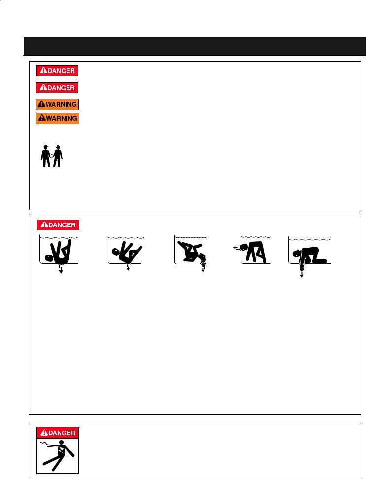
SUCTION ENTRAPMENT HAZARD
Pool and spa pumps move large volumes of water, which can pose extreme danger if a person’s hair comes in close proximity to a drain that is not the proper size for the pump or pumps.
Hair Entanglement – When the hair tangles or knots in the drain cover, trapping the swimmer underwater. This hazard is present when the flow rating of the cover is too small for the pump or pumps.
Limb Entrapment – When a limb is sucked or inserted into an opening resulting in a mechanical bind or swelling. This hazard is present when a drain cover is missing, broken, loose, cracked or not properly secured.
Body Entrapment – When a portion of the body is held against the drain cover trapping the swimmer underwater. This hazard is present when the drain cover is missing, broken or the cover flow rating is not high enough for the pump or pumps.
Evisceration/Disembowelment – When a person sits on an open pool
(particularly a child wading pool) or spa outlet and suction is applied directly to the intestines, causing severe intestinal damage. This hazard is present when the drain cover is missing, loose, cracked, or not properly secured.
Mechanical Entrapment – When jewelry, swimsuit, hair decorations, finger, toe or knuckle is caught in an opening of an outlet or drain cover. This hazard is present when the drain cover is missing, broken, loose, cracked, or not properly secured.
RISK OF ELECTRICAL SHOCK OR ELECTROCUTION:
PUMPS REQUIRE HIGH VOLTAGE WHICH CAN SHOCK, BURN, OR CAUSE DEATH. BEFORE WORKING ON PUMP!
Always disconnect power to the pool pump at the circuit breaker from the pump before servicing the pump. Failure to do so could result in death or serious injury to service person, pool users or others due to electric shock.
IntelliFlo VF Installation and User’s Guide

iv
IMPORTANT SAFETY PRECAUTIONS (continued)
Water temperature in excess of 100° F (37.7° C) may be hazardous to your health. Prolonged immersion in hot water may induce hyperthermia. Hyperthermia occurs when the internal temperature of the body reaches a level several degrees above normal body temperature of 98.6° F (37° C.). Effects of hyperthermia include: (1) Unawareness of impending danger. (2) Failure to perceive heat. (3) Failure to recognize the need to leave the spa. (4) Physical inability to exit the spa. (5) Fetal damage in pregnant women. (6) Unconsciousness resulting in danger of drowning. The use of alcohol, drugs, or medication can greatly increase the risk of fatal hyperthermia in hot tubs and spas.
When setting up pool water turnovers or flow rates the operator must consider local codes governing turnover as well as disinfectant feed ratios.
DO NOT increase pump size; this may increase the flow rate through the system and exceed the maximum flow rate stated on the drain cover.
Do not permit children to operate this product.
If this pump is intended for use other than single-family dwellings, a clearly labeled emergency switch shall be provided as part of the installation. The switch shall be readily accessible to the occupants and shall be installed at least 5 feet (1.52 m) away, adjacent to, and within sight of, the unit.
When setting up pool water turnovers or flow rates the operator must consider local codes governing turnover as well as disinfectant feed ratios.
Before servicing the system, switch the main power OFF and remove the communication cable from the pump.
Install the pump a minimum of five (5) feet from the inside wall of the pool and spa. Canadian installations require a minimum of three (3) meters from pool water.
A No. 8 AWG (No. 6 AWG in Canada) or larger conductor must be wired to the motor bonding lug.
This pump is for use with permanently installed pools and may also be used with hot tubs and spas if so marked. Do not use with storable pools. A permanently installed pool is constructed in or on the ground or in a building such that it cannot be readily disassembled for storage. A storable pool is constructed so that it may be readily disassembled for storage and reassembled to its original integrity and has a maximum dimension of 18 feet (5.49m) and a maximum wall height of 42 inches (1.07m).
For hot tubs and spa pumps, do not install within an outer enclosure or beneath the skirt of a hot tub or spa unless so marked.
The IntelliPro pump is capable of generating systems pressures up to 50 psi. Installers must ensure that all system components are rated to withstand at least 50 psi. Over pressurizing the system can result in catastrophic component failure or property damage.
Never exceed the maximum stated pump flow rating.
Only use a pumping system rated for the corresponding flow. FAILURE TO DO SO CAN RESULT IN HAIR OR BODY ENTRAPMENT WHICH CAN CAUSE SERIOUS PERSONAL INJURY OR DEATH. If in doubt about the rating of your system, consult a qualified pool service professional.
Pumps are not a substitute for properly installed and secured pool drain covers. An ANSI/ ASME A112.19.8 approved anti-entrapment drain cover must be used for each drain. Pools and spas should utilize a minimum of two drains per pump. Regularly inspect all covers for cracks, damage and advanced weathering. If a cover becomes loose, cracked, damaged, broken or is missing, close the pool or spa immediately, shut off the pump, post a notice and keep the pool or spa closed until an appropriate VGB 2008 certified cover is properly installed. Covers deteriorate over time due to exposure to sunlight and pool chemicals. This cover must be replaced within seven (7) years from installation (or earlier if the cover becomes damaged in any way).
IntelliFlo VF Installation and User’s Guide

v
IMPORTANT SAFETY PRECAUTIONS (continued)
Entrapment Avoidance Notice:
The suction outlet connected to a swimming pool or spa pump can pull a high vacuum if it is blocked. Therefore, if only one suction outlet smaller than 18" x 23" is used, anyone blocking the suction outlet with their body can be trapped and held against the suction outlet. Disembowelment or drowning can result. Therefore, if small suction outlets are used with this pump, to prevent this entrapment and possible death, install at least two suction outlets in the body of water. Separate these suction outlets as described in the International Residential Code (IRC), the International Business Code (IBC), the Consumer Products Safety Council (CPSC) Guidelines for Entrapment Hazards: Making Pools and Spas Safer or ANSI/IAF-7 Standard for Suction Entrapment Avoidance in Swimming Pools, Wading Pools, Spas, Hot Tubs and Catch Basins. If suction outlets are not used, additional entrapment avoidance measures as described in the CPSC Guidelines or ANSI/IAF-7 should be employed.
The covers used on suction outlets should be approved and listed as conforming to the currently published edition of ANSI/ASME A112.19.8 Standard covering Suction Fittings for Use in Swimming Pools, Wading Pools, Spas and Hot Tubs. These covers should be inspected regularly and replaced if cracked, broken or older than the design lifetime indicated on them by the manufacturer. The maximum possible flow rate of this pump should be less than or equal to the maximum approved flow rate indicated on the suction outlet cover by the manufacturer. THE USE OF UNAPPROVED COVERS OR ALLOWING USE OF THE POOL OR SPA WHEN COVERS ARE CRACKED OR BROKEN CAN RESULT IN HAIR ENTANGLEMENT WHICH CAN RESULT IN DEATH.
The Virginia Graeme Baker Pool and Spa Safety Act imposes certain new requirements on owners and operators of swimming pools and spas.
Pools or spas constructed on or after December 20, 2008, shall utilize:
(A)No submerged suction outlets, a gravity drainage system with ASME/ANSI cover(s), one or more unblockable outlets; or
(B)A multiple main drain system without isolation capability with suction outlet covers that meet ASME/ ANSI A112.19.8 Suction Fittings for Use in Swimming Pools, Wading Pools, Spas, and Hot Tubs and either:
(i)A safety vacuum release system (SVRS) meeting ASME/ANSI A112.19.17 Manufactured Safety Vacuum Release Systems (SVRS) for Residential and Commercial Swimming Pool, Spa, Hot Tub, and Wading Pool Suction Systems and/or ASTM F2387 Standard Specification for Manufactured Safety Vacuum Release Systems (SVRS) for Swimming Pools, Spas and Hot Tubs or
(ii)A properly designed and tested suction-limiting vent system or
(iii)An automatic pump shut-off system.
Pools and spas construction prior to December 20, 2008, with a single submerged suction outlet shall use a suction outlet cover that meets ASME/ANSI A112.19.8 and either:
(A)A multiple main drain system without isolation capability, or
(B)A safety vacuum release system (SVRS) meeting ASME/ANSI A112.19.17 and/or ASTM F2387, or
(C)A properly designed and tested suction-limiting vent system, or
(D)An automatic pump shut-off system, or
(E)Disabled submerged outlets, or
(F)Suction outlets shall be reconfigured into return inlets.
For information about the Virginia Graeme Baker Pool and Spa Safety Act, contact the Consumer Product Safety Commission at (301) 504-7908 or visit www.cpsc.gov.
NOTE: Always turn off all power to the pool pump before installing the cover or working on any suction outlet.
IntelliFlo VF Installation and User’s Guide

vi
IMPORTANT SAFETY PRECAUTIONS (continued)
General Installation Information
•All work must be performed by a qualified pool professional, and must conform to all national, state, and local codes.
•Install to provide drainage of compartment for electrical components.
General Installation Information
Pumps improperly sized or installed or used in applications other than for which the pump was intended can result in severe personal injury or death. These risks may include but not be limited to electric shock, fire, flooding, suction entrapment or severe injury or property damage caused by a structural failure of the pump or other system component.
The pump can produce high levels of suction within the suction side of the plumbing system. These high levels of suction can pose a risk if a person comes within the close proximity of the suction openings. A person can be seriously injured by this high level of vacuum or may become trapped and drown. It is absolutely critical that the suction plumbing be installed in accordance with the latest national and local codes for swimming pools.
•These instructions contain information for a variety of pump models and therefore some instructions may not apply to a specific model. All models are intended for use in swimming pool applications. The pump will function correctly only if it is properly sized to the specific application and properly installed.
General Warnings
•Never open the inside of the drive motor enclosure. There is a capacitor bank that holds a 230 VAC charge even when there is no power to the unit.
•The IntelliPro VS-3050 pump is not submersible
•The IntelliPro VS-3050 pump is capable of 174 GPM or 104 feet of head; use caution when installing and programming to limit pumps performance potential with old or questionable equipment
•Code requirements for the electrical connection differ from state to state. Install equipment in accordance with the National Electrical Code and all applicable local codes and ordinances.
•Always Press the Stop button and disconnect the communication cable before performing maintenance, and always power the unit off by disconnecting the main circuit to the pump
Two Speed Pump Controls Notice (Title 20 Compliance)
Please read the following important Safety Instructions. When using two-speed pumps manufactured on or after January 1, 2008, the pump's default circulation speed MUST be set to the LOWEST SPEED, with a high speed override capability being for a temporary period not to exceed one normal cycle, or two hours, whichever is less.
IntelliFlo VF Installation and User’s Guide

1
Section 1
Introduction
IntelliFlo® VF Overview
The IntelliFlo VF variable-flow pump control system offers pool and spa filter automation and advanced features that include energy conservation and programmable scheduled water features for your pool, spa, cleaner, waterfall, and other applications.
The IntelliFlo pump can adapt to any application up to 130 gallons per minute, you simply program IntelliFlo to suit the application. IntelliFlo then dials in the perfect operating conditions for that specific flow rate.
IntelliFlo can reduce energy cost by as much as 90% based on a pool size up to 15,000 gallons, one turn per day with a 24 hour cycle.
IntelliFlo constantly monitors water flow and electrical current to ensure that the filtration system is operating at peak efficiency. This can result in maximum energy efficiency savings never before possible – up to 90% over conventional single speed and two speed pumps. The system protects against loss of prime or impedance of flow, under and over voltage situations, and thermal overload or freezing.
With IntelliFlo there’s no need for pump curves and hydraulic calculations to determine the right pump for the job. Just set the program for your pool size and desired turnover, and IntelliFlo does the rest.
Motor fan cover
Motor assembly
Drive assembly and electronics enclosure
Communication port for connection to EasyTouch, IntelliTouch or SunTouch control system or IntelliComm communication center via two-wire RS-485 cable
IntelliFlo VF (variable flow pump)
IntelliFlo VF Installation and User’s Guide
2
IntelliFlo Features
•Sizes itself to any pool
•Reduces energy cost by as much as 90%
•Protects against loss of prime or flow blockage
•Prevents thermal overload
•Detects and prevents damage from under and over voltage conditions
•Protects against freezing
•Can communicate with an IntelliTouch or IntelliComm system via a two-wire connection
•Easy to read operator control panel LCD display
•Operator control panel buttons for pump modes
•Built-in strainer pot and volute
•Ultra energy-efficient TEFC Square Flange Motor
•Compatibility with most cleaning systems, filters, and jet action spas
•16-button LCD control panel
•Drive assembly features permanent magnet synchronous motor
•Heavy-duty, durable construction designed for long life
•Internal 24-hour clock for setting controlled on/off times for filtering and up to ten water features
•UL listed
IntelliFlo Motor Assembly
The IntelliFlo’s three-phase, six-pole, permanent magnet motor operates at 3450 RPM (at 92% efficiency) and 400 RPM (at 90%). The motor assembly is continually cooled by an external fan. Dual seals on the motor shaft and at the fan assembly seal the entire motor from any moisture entering the motor assembly. For added protection, a slinger located in front of the main shaft seal assists in slinging water away from the shaft opening in the flange.
IntelliFlo VF Installation and User’s Guide
3
Operator control panel cover
Drive assembly and electronics enclosure
Motor fan cover
 Motor assembly
Communication Port for RS-485 (IntelliTouch and IntelliComm)
Motor stand
IntelliFlo VF Motor Assembly
IntelliFlo VF Motor Features
•Permanent Magnet Synchronous Motor (PMSM)
•High efficiency (3450 RPM 92% and 400 RPM 90%)
•Superior speed control
•Operates at lower temperatures due to high efficiency
•Same technology as deployed in hybrid electric vehicles
•Designed to withstand outdoor environment
•Totally Enclosed Fan Cooled
•Three-phase motor
•56 Square Flange
•Six-Pole
•Low noise
IntelliFlo VF Installation and User’s Guide

4
IntelliFlo Drive Assembly and Control Panel
The IntelliFlo drive assembly consists of an operator control panel and the system electronics that drive the 230 VAC single phase (260 VAC~170 VAC) motor. The drive microprocessor controls the motor by changing the frequency of the current it receives together with changing the voltage to control the rotational speed.
Operator Control Panel, buttons and LED (see page 5)
AC power connection compartment  (see page 32)
Motor stand 
IntelliFlo Drive Assembly
Operator Control Panel Features
•Backwash and Rinse — Informs the user when and how to backwash filter media
•Vacuum — Can be preset using duration and flow parameters to save energy
•Filter — Allows pump to run at peak efficiency, saving users up to 90% in energy cost, based on a pool size up to 15,000 gallons, one turn per day with a 24 hour cycle
•Feature — Ten feature modes can be programmed to control filtration duration, start and stop time, and frequency for cleaners, water features, spas, and waterfalls
•Manual — Allows the user to override all programming and run the pump using RPM or flow (GPM) control parameters. All personnel safety devices and alarms do not operate in speed mode.
IntelliFlo VF Installation and User’s Guide

5
Section 2
Operator Control Panel
This section describes the operator control panel controls and LEDs.
IntelliFlo VF Operator Control Panel
|
|
IntelliFlo® |
|
||
15 |
|
|
|
|
|
|
Filter |
Vacuum |
Back |
Manual |
|
|
mode |
mode |
Wash |
mode |
|
1 |
|
|
|
|
4 |
2 |
Select |
|
Escape |
3 |
|
|
|
|
|||
|
|
|
|
||
5 |
|
|
|
|
6 |
|
On |
Enter |
|
Menu |
7 |
|
|
|
|
|
|
14 |
Warn. |
|
|
|
|
|
Alarm |
|
|
|
8 |
|
|
|
|
|
|
|
|
|
|
|
9 |
|
Feature |
Feature |
Start |
Reset |
|
|
1 |
2 |
Stop |
|
|
|
|
|
|||
10 |
|
|
|
|
13 |
11 |
|
|
|
|
12 |
Controls and LEDs
1Filter button/LED: Starts Filter mode. The LED is on when Filter mode is active.
2Vacuum button/LED: Starts Vacuum mode. The LED is on when Vacuum mode is active.
3Backwash button/LED: Starts Backwash mode. The LED is on when Backwash mode is active.
4Manual button/LED: Starts Manual mode. The LED is on when Manual mode is active.
5Select button: Display available menu items or enters edit mode for changing a value on line two of the display.
6Escape button: Go to the next level up in the menu structure or stop editing the current setting.
7Menu button: Access the menu items if the pump is stopped.
8Enter button: Save current menu item setting. Also, press this button to acknowledge alarms and warning alerts.
IntelliFlo VF Installation and User’s Guide

6
Controls and LEDs (Continued)
9Arrow buttons:
•Up arrow: Move one level up in the menu tree or increase a digit when editing a setting.
•Down arrow: Move one level down in the menu tree or decrease a digit when editing a setting.
•Left arrow: Move cursor left one digit when editing a setting.
•Right arrow: Move cursor right one digit when editing a setting.
10Feature 1 button: Starts Feature 1 mode. The LED is lit when mode is active.
11Feature 2 button: Starts Feature 2 mode. The LED is lit when mode is active.
12Start/Stop button: Start or Stop the pump. When the LED is lit it indicates that the pump is currently running or in a mode to start automatically.
13Reset button: Reset alarm or alert.
LEDs
On: This green LED is on when IntelliFlo is powered on.
14Warning: This LED is on if a warning condition is present.
Alarm: This LED is on if an alarm condition has occurred.
15Control Panel LCD Display
LCD Display Lines:
•Line 1 - Mode and time. To set A.M. and P.M. time, refer to “Time and Contrast Menu” on page 22.
•Line 2 - Data
•Line 3 - Name of data in line 2
•Line 4 - Run status
IntelliFlo VF Installation and User’s Guide

7
Navigating the Menu Structure
Before navigating the control panel menu structure, first familiarize yourself with the menu buttons. To change a parameter setting, use the Left and Right arrow buttons to select the digit, then the Up and Down arrow buttons to edit the digit. The following example shows how to set the GPM and priming time in the “Priming” menu (see page 14).
To set the “Priming” mode settings:
1. Ensure that the green power LED is on and the pump is stopped. If the pump is running, press the Start/Stop button.
2. Press the
Menu
Menu button. “Pool Data” is displayed.
3. Press the  Down arrow to select “Priming”.
4. Press the
Select
Select button to access “Max Priming Flow” setting.
5. Set the GPM: Press the
(GPM) value.
Select
Select button to set the gallons per minute
6. To change the GPM value, press the |
Left and Right arrows to select |
which digit to modify. |
|
Press the  Up and Down arrows to change the selected digit. For setting values, see “Priming menu options” below.
7. When you are done, press the Enter Enter button to save the changes. To cancel any changes.
Press the
Escape
Escape button to exit edit mode without saving.
8. Set the priming time: Use the  Up and Down arrows to select “Max Priming Time” and “System Priming Time.”
Press the
Select
Select to edit the setting.
9. Repeat steps 5, 6, and 7 to edit the setting.
8
Blank Page
IntelliFlo VF Installation and User’s Guide

9
Section 3
Operating IntelliFlo
This section describes how to use the IntelliFlo pump control panel.
Metering the System
The first step to operating and programming IntelliFlo is to know what is being used in the pool system.After the devices are selected you can then set valves for the appropriate features and use the “Manual” mode to measure flow rates for the types or series of devices that require flow. When an appropriate flow rate or rates are found for a device or series of devices, you should note that flow rate for programming later.
Note: If the pool system uses a filter, always monitor pressure at the filter when changing the speed (RPM) or flow (GPM) from IntelliFlo.
Manual Mode
Operating IntelliFlo in manual mode is typically used for service and testing purposes only.
To operate IntelliFlo in manual mode:
1.Ensure that the green power LED is on.
2.Press the Manual button.
3.Use the Up and Down arrow buttons to view the current power, actual speed and flow:
•Power Menu (Watts): Displays current power to the motor shaft in continuous watts
•Actual Speed (RPM): Displays RPM speed when flow and RPM control is used
•Actual Flow (GPM): Displays actual flow when using flow control
•Set Speed (RPM): Set IntelliFlo to run at a continuous speed
•Set Flow (GPM): Set IntelliFlo in flow control to allow the pump to change speed to manage the flow rate based on system changes
IntelliFlo®
MANUAL 12:15
15.W
POWER
STOPPED
Back
Filter Vacuum Manual
Wash
Select |
|
|
Escape |
|
On |
Enter |
|
Menu |
|
Warn. |
|
|
|
|
Alarm |
|
|
|
|
Feature |
Feature |
Start |
Reset |
|
1 |
2 |
Stop |
||
|
IntelliFlo®
MANUAL 12:15
10.RPM
ACTUAL SPEED
STOPPED
Filter |
Vacuum |
Back |
Manual |
|
Wash |
||||
|
|
|
||
Select |
|
|
Escape |
|
On |
Enter |
|
Menu |
|
Warn. |
|
|
|
|
Alarm |
|
|
|
|
Feature |
Feature |
Start |
Reset |
|
1 |
2 |
Stop |
||
|
IntelliFlo®
MANUAL 12:15
13.GPM
FLOW
STOPPED
Back
Filter Vacuum Manual
Wash
Select |
|
|
Escape |
|
On |
Enter |
|
Menu |
|
Warn. |
|
|
|
|
Alarm |
|
|
|
|
Feature |
Feature |
Start |
Reset |
|
1 |
2 |
Stop |
||
|
IntelliFlo®
MANUAL 12:15
10.RPM
Set SPEED
STOPPED
Filter |
Vacuum |
Back |
Manual |
|
Wash |
||||
|
|
|
||
Select |
|
|
Escape |
|
On |
Enter |
|
Menu |
|
Warn. |
|
|
|
|
Alarm |
|
|
|
|
Feature |
Feature |
Start |
Reset |
|
1 |
2 |
Stop |
||
|
IntelliFlo®
MANUAL 12:15
580.GPM
Set FLOW
STOPPED
Filter |
Vacuum |
Back |
Manual |
|
Wash |
||||
|
|
|
||
Select |
|
|
Escape |
|
On |
Enter |
|
Menu |
|
Warn. |
|
|
|
|
Alarm |
|
|
|
|
Feature |
Feature |
Start |
Reset |
|
1 |
2 |
Stop |
||
|
Manual
Note: No sensors except the flow control will work while in “Manual” mode. Suction Blockage will not work in this mode.
IntelliFlo VF Installation and User’s Guide

10
Manual Mode (Continued)
To change the Set Flow and Set Speed features:
1.Ensure that the green power LED is on.
2.Press the Manual button (LED is on).
3.Set Flow: Use the Up and Down arrow buttons to select Set Flow, then press the Select button to edit the setting.
4.To change the setting, press the Left and Right arrows to select which digit to modify, then use the Up and Down arrows to change the selected digit. The preset flow values can be set to 15 to 130 GPM (default 50 GPM).
5.When you are done, press the Enter button to save the changes. To cancel any changes, press the Escape button to exit edit mode without saving.
6.Set Speed: Use the Up and Down arrows to select Set Speed, then press the Select button to edit the setting. The preset speed can be set to 400 to 3450 RPM maximum (default 1000 RPM).
Select
IntelliFlo®
MANUAL 12:15
0010.RPM
Set SPEED
STOPPED
Filter |
Vacuum |
Back |
|
Manual |
|
Wash |
|||||
|
|
|
|||
elect |
|
|
E |
|
|
|
s |
||
|
|
|
c |
|
|
|
|
a |
|
S |
|
|
pe |
|
On |
Enter |
|
uMen |
|
Warn. |
|
|
|
|
Alarm |
|
|
|
|
Feature |
Feature |
Start |
Reset |
|
1 |
2 |
Stop |
||
|
Cursor hi-lights in black
IntelliFlo®
MANUAL 12:15
 010.RPM
Set SPEED
STOPPED
Back
Filter Vacuum Manual
Wash
elect |
|
|
E |
|
|
|
s |
||
|
|
|
c |
|
|
|
|
a |
|
S |
|
|
pe |
|
On |
Enter |
|
uMen |
|
Warn. |
|
|
|
|
Alarm |
|
|
|
|
Feature |
Feature |
Start |
Reset |
|
1 |
2 |
Stop |
||
|
Left/Right arrow buttons to change digit
IntelliFlo®
MANUAL 12:15
1010.RPM
Set SPEED
STOPPED
Back
Filter Vacuum Manual
Wash
elect |
|
|
E |
|
|
|
s |
||
|
|
|
c |
|
|
|
|
a |
|
S |
|
|
pe |
|
On |
Enter |
|
uMen |
|
Warn. |
|
|
|
|
Alarm |
|
|
|
|
Feature |
Feature |
Start |
Reset |
|
1 |
2 |
Stop |
||
|
Press the Enter
button to save.
Press Start/Stop
Enter
Start
Stop
7.To change the setting, press the Left and Right arrows to select which digit to modify, then use the Up and Down arrows to change the selected digit.
8.When you are done, press the Enter button to save the changes. To cancel any changes, press the Escape button to exit edit mode without saving.
IntelliFlo VF Installation and User’s Guide
11
Manual Mode (Continued)
9.Press the Start/Stop button (LED is on) to run IntelliFlo in “Manual” mode (LED is on). The pump will start and control the flow or speed using the last settings made. After the button is pressed, the display shows “Running.” To stop IntelliFlo, press the Start/Stop button (LED is off). The display will show “Stopped.”
Note: While IntelliFlo is running in Manual mode, you can view the current power consumption and what actual speed is being used.
10.Change Flow and Speed settings while the IntelliFlo is running: The Set Flow and Set Speed settings can be changed on the fly while the pump is running. To change the flow and speed settings, perform steps 3 through 8.
•When “Set Flow” is used IntelliFlo will prime then ramp to the current flow rate
•It takes the IntelliFlo about 60 seconds to two minutes to find a flow rate after it is primed. This is best seen inActual Speed status display
•While changing the Set Flow setting, IntelliFlo will reprime after a value is changed
•While changing the Set Speed setting, IntelliFlo will immediately ramp to the current speed
11.To stop the pump, press the Start/Stop button.
IntelliFlo Control Panel Menu
Use the control panel menu to setup and configure IntelliFlo.
To access the menu features:
•Ensure that the pump is stopped. Press the Menu button. Use the Up or Down arrow button to scroll through the menu items. Use the Select button to select a menu item. Press the Enter button to save a setting. Press the Escape button to move up a level from a selected menu item.
Menu Structure
The IntelliFlo menu structure is shown on the following page.
IntelliFlo Control Panel with IntelliComm or IntelliTouch
•The IntelliFlo control panel remains active when the IntelliFlo is connected to an IntelliComm. For more information see page 29.
•The IntelliFlo control panel is disabled when the Intelliflo is communicating with an IntelliTouch. "DISPLAY NOT ACTIVE!" will be displayed. For more information see page 31.
IntelliFlo VF Installation and User’s Guide

12
Main Menu
MAIN SCREEN Press MENU button to access menu items
POOL DATA
(page 13)
PRIMING (page 14)
FILTER
(page 16)
TIME / CONTR
(page 22)
FEATURES
(page 23)
|
|
|
Address |
|
|
|
|
(1 - 16) [Note: 1-8 when connected to IntelliTouch] |
||||||||
|
|
|
|
|
||||||||||||
|
|
|
|
|
|
|
|
|
(68° - 104° F) |
|||||||
|
|
|
Water |
Temp |
|
|
|
|||||||||
|
|
|
|
|
|
|
|
|
(1 - 1000 Kgal) |
|||||||
|
|
|
Pool Volume |
|
|
|
|
|||||||||
|
|
|
|
|
|
|
|
|
|
(30 - 160 gpm) |
||||||
|
|
|
Max Priming Flow |
|
|
|
|
|
||||||||
|
|
|
|
|
|
|
|
|
|
|
|
(1 - 15 min.) |
||||
|
|
|
Max Priming Time |
|
|
|
|
|
|
|
||||||
|
|
|
|
|
|
|
|
|
|
|
|
(0 - 5 min.) |
||||
|
|
|
Sys Priming Time |
|
|
|
|
|
|
|
||||||
|
|
|
|
|
|
|
|
|
|
|
|
|
(1 - 50 min.) |
|||
|
|
|
Clean Filter Pressure |
|
|
|
|
|
|
|
|
|||||
|
|
|
|
|
|
|
|
|
|
|
|
|
(1 - 8 counts) |
|||
|
|
|
Turnovers |
per Day |
|
|
|
|
|
|
|
|
||||
|
|
|
|
|
|
|
|
|
|
|
|
|
(1 - 4 counts) |
|||
|
|
|
Cycles per Day |
|
|
|
|
|
|
|||||||
|
|
|
|
|
|
|
|
|
|
|
|
|
(hr:mm - AM/PM) |
|||
|
|
|
Start Cycle 1 |
|
|
|
|
|
|
|
||||||
|
|
|
|
|
|
|
|
|
|
|
|
|
(hr:mm - AM/PM) |
|||
|
|
|
Stop Cycle 1 |
|
|
|
|
|
|
|
|
|||||
|
|
|
|
|
|
|
|
|
|
|
|
|
(hr:mm - AM/PM) |
|||
|
|
|
Start |
Cycle 2 |
|
|
|
|
|
|
|
|
||||
|
|
|
|
|
|
|
|
|
|
|
|
|
(hr:mm - AM/PM) |
|||
|
|
|
Stop Cycle 2 |
|
|
|
|
|
|
|
|
|||||
|
|
|
|
|
|
|
|
|
|
|
|
|
(hr:mm - AM/PM) |
|||
|
|
|
Start |
Cycle 3 |
|
|
|
|
|
|
|
|
||||
|
|
|
|
|
|
|
|
|
|
|
|
|
|
(hr:mm - AM/PM) |
||
|
|
|
Stop Cycle 3 |
|
|
|
|
|
|
|
|
|
||||
|
|
|
|
|
|
|
|
|
|
|
|
|
|
(hr:mm - AM/PM) |
||
|
|
|
Start |
Cycle 4 |
|
|
|
|
|
|
|
|
|
|||
|
|
|
|
|
|
|
|
|
|
|
|
|||||
|
|
|
|
|
|
|
|
|
|
|
|
|
|
(hr:mm - AM/PM) |
||
|
|
|
Stop Cycle 4 |
|
|
|
|
|
|
|
|
|
||||
|
|
|
|
|
|
|
|
|
|
|
|
|||||
|
|
|
|
|
|
|
|
|
|
|
|
|
|
|
|
(hr:min - AM/PM) |
|
|
|
Clock |
|
|
|
|
|
|
|
|
|
|
|
||
|
|
|
|
|
|
|
|
|
|
|
|
|
|
(0 - 9) |
||
|
|
|
Contrast Level |
|
|
|
|
|
|
|
|
|
||||
|
|
|
|
|
|
|
|
|
|
|
|
|
|
|
|
Set Flow (15 - 130 gpm) |
|
|
|
Features 1 |
|||||||||||||
|
|
|
|
|
|
|
|
|
|
|
|
|
||||
|
|
|
|
|
|
|
|
|
|
|
|
|
|
|
|
Set Duration (0:01 - 10:00) |
|
|
|
|
|
|
|
|
|
|
|
|
|
|
|
||
Features 2
Features 3
Features 4
Features 5
Features 6
Features 7

 Set Flow (15 - 130 gpm) Set Duration (0:01 - 10:00)

 Disable/Enable
Set Flow (15 - 130 gpm)
Set Start Time (hr:mm AM/PM)
Set Stop Time (hr:mm AM/PM)
 Disable/Enable
Set Flow (15 - 130 gpm)
Set Start Time (hr:mm AM/PM)
Set Stop Time (hr:mm AM/PM)
 Disable/Enable
Set Flow (15 - 130 gpm)
Set Start Time (hr:mm AM/PM)
Set Stop Time (hr:mm AM/PM)
 Disable/Enable
Set Flow (15 - 130 gpm)
Set Start Time (hr:mm AM/PM)
Set Stop Time (hr:mm AM/PM)
 Disable/Enable
Set Flow (15 - 130 gpm)
Set Start Time (hr:mm AM/PM)
Set Stop Time (hr:mm AM/PM)
Features 8
Features 9
M.O Flow
 Disable/Enable
Set Flow (15 - 130 gpm)
Set Start Time (hr:mm AM/PM)
Set Stop Time (hr:mm AM/PM)
 Disable/Enable
Set Flow (15 - 130 gpm)
Set Start Time (hr:mm AM/PM)
Set Stop Time (hr:mm AM/PM)
 Disable/Enable
Set Flow (15 - 130 gpm)
Set Run Time (0:01 - 00:59)
Set Interval Time (0:02 - 4:15)
EXT. CONTROL
(page 29)
BACKWASH
(page 33)
VACUUM
(page 35)
|
Program 1 |
|
|
|
|
Disable/Enable |
|
|
|
|
|
|
|||
|
|
|
|
|
|
|
Set Flow (15 130 gpm) / Time Delay Stop (hr:mn) (0:00 - 0:10) |
|
|
|
|
||||
|
|
|
|
|
|
|
Disable/Enable (15 - 130 gpm) |
|
Program 2 |
|
|
|
|
||
|
|
|
|
|
|
|
Set Flow (15 130 gpm) / Time Delay Stop (hr:mn) (0:00 - 0:10) |
|
|
|
|
|
|
|
Disable/Enable |
|
Program 3 |
|
|
|
|
||
|
|
|
|
|
|
|
Set Flow (15 130 gpm) / Time Delay Stop (hr:mn) (0:00 - 0:10) |
|
|
|
|
|
|
|
Disable/Enable |
|
Program 4 |
|
|
|
|
||
|
|
|
|
|
|
|
Set Flow (15 130 gpm) / Time Delay Stop (hr:mn) (0:00 - 0:10) |
|
|
|
|
|
|
|
|
|
|
|
|
|
|
|
(15 - 130 gpm) |
|
Backwash Flow |
|
|
|
|
||
|
|
|
|
|
(0:01 - 1:00) |
||
|
Backwash Duration |
|
|
||||
|
|
|
|
(0:01 - 1:00) |
|||
|
Rinse Time |
|
|||||
|
|
|
|
|
|
|
(15 - 130 gpm) |
|
Vacuum Flow |
|
|
|
|
||
|
|
|
|
(0:01 - 10:00) |
|||
|
Vacuum Duration |
|
|||||
IntelliFlo VF Installation and User’s Guide
 Loading...