


CVA-24T
Rev. F 3-26-04 1 P/N 520050
LX-100EZ EASYTOUCH POOL/SPA CONTROL SYSTEM
INSTALLATION AND OWNERS MANUAL
IMPORTANT SAFETY INSTRUCTIONS
READ AND FOLLOW ALL INSTRUCTIONS
SAVE THESE INSTRUCTIONS
Pentair Pool Products
1620 Hawkins Ave., Sanford, NC 27330 • (919) 774-4151
10951 West Los Angeles Ave., Moorpark, CA 93021 • (805) 523-2400
Important Notice
Attention Installer.
This manual contains important information about the installation, operation and safe use of this
product. This information should be given to the owner/operator of this equipment.

P/N 520050 2 Rev. F 3-26-04
INSTALLATION MANUAL
IMPORTANT SAFETY INSTRUCTIONS ...............................................................................5
SYSTEM INCLUDES............................................................................................................................... 5
EQUIPMENT LOCATION..................................................................................................................... 5
RECOMMENDED HYDRAULIC SCHEMATIC ................................................................... 6
PLUMBING REQUIREMENTS............................................................................................... 7
LX-100 RF POWER/LOAD CENTER .................................................................................... 8
HIGH VOLTAGE WIRING...................................................................................................... 8
GENERAL.................................................................................................................................................. 8
SYSTEM POWER ..................................................................................................................................... 8
EQUIPMENT POWER ............................................................................................................................ 8
LOW VOLTAGE CABLES ...................................................................................................... 9
LOW VOLTAGE WIRING ....................................................................................................... 9
RECEIVER CIRCUIT BOARD ............................................................................................... 10
CUSTOMIZING THE COMMUNICATION LINK .................................................................11
VALVE ACTUATORS ............................................................................................................. 12
RECEIVER ANTENNA ........................................................................................................... 12
HEATER CONNECTIONS ...................................................................................................... 1 3
DUAL THERMOSTAT GAS HEATER ............................................................................................... 13
SINGLE THERMOSTAT GAS HEATER ............................................................................................ 13
ELECTRIC HEATER OR HEAT PUMP ............................................................................................ 13
SYSTEM OPTIONS ............................................................................................................... 1 4
AUTOMATIC COUNTDOWN CYCLE ............................................................................................. 14
SPA-SIDE REMOTE CONTROL ........................................................................................................ 15
POOL CLEANER ................................................................................................................................... 16
AUXILIARY VALVE ............................................................................................................................. 16
WATER TEMPERATURE SENSOR .................................................................................................... 17
CP-100 INDOOR CONTROLLER....................................................................................................... 18
SYSTEM START-UP ........................................................................................................ 19-20

Rev. F 3-26-04 3 P/N 520050
OWNER’S MANUAL
IMPORTANT SAFETY INSTRUCTIONS ............................................................................ 2 1
INTRODUCTION .................................................................................................................... 22
SAFETY FEATURES .............................................................................................................. 22
HEATER PROTECTION ....................................................................................................................... 22
POOL CLEANER PROTECTION ....................................................................................................... 22
HAND-HELD REMOTE ......................................................................................................... 22
LX-100 RF POWER/LOAD CENTER ................................................................................. 2 3
FILTER PUMP and POOL CLEANER Time Clocks ....................................................................... 23
SPA Service Switch ................................................................................................................................. 24
FILTER Service Switch .......................................................................................................................... 24
AUX1, AUX2 and AUX3 Service Switches........................................................................................ 24
HEATER Switch ....................................................................................................................................... 24
PUMP DELAY Status Light .................................................................................................................. 24
POWER ON Status Light ....................................................................................................................... 24
MOTORIZED VALVES .......................................................................................................... 25
SYSTEM OPTIONS ............................................................................................................... 2 6
SPA-SIDE REMOTE CONTROL ........................................................................................................ 26
INDOOR CONTROLLER .................................................................................................................... 27
MAINTENANCE ..................................................................................................................... 2 8
CLEANING THE SPA............................................................................................................................ 28
WINTERIZING THE SYSTEM ............................................................................................................ 28
TRANSMITTER BATTERY REPLACEMENT ................................................................................ 28
TROUBLE-SHOOTING .......................................................................................................... 2 9
GENERAL................................................................................................................................................. 29
NOTHING OPERATES .......................................................................................................................... 29
FILTER PUMP DOES NOT OPERATE ............................................................................................. 29
FILTER PUMP DOES NOT TURN OFF ........................................................................................... 29
POOL CLEANER DOES NOT OPERATE ........................................................................................ 29
HEATER DOES NOT OPERATE ........................................................................................................ 29
SPA WATER LEVEL DROPS .............................................................................................................. 29
RF TROUBLE-SHOOTING TABLE ................................................................................................... 30
WARRANTY ............................................................................................................................ 31

P/N 520050 4 Rev. F 3-26-04
This page is blank.
Rev. F 3-26-04 5 P/N 520050
INSTALLATION MANUAL
LX-100EZ EASYTOUCH POOL-SPA CONTROL SYSTEM
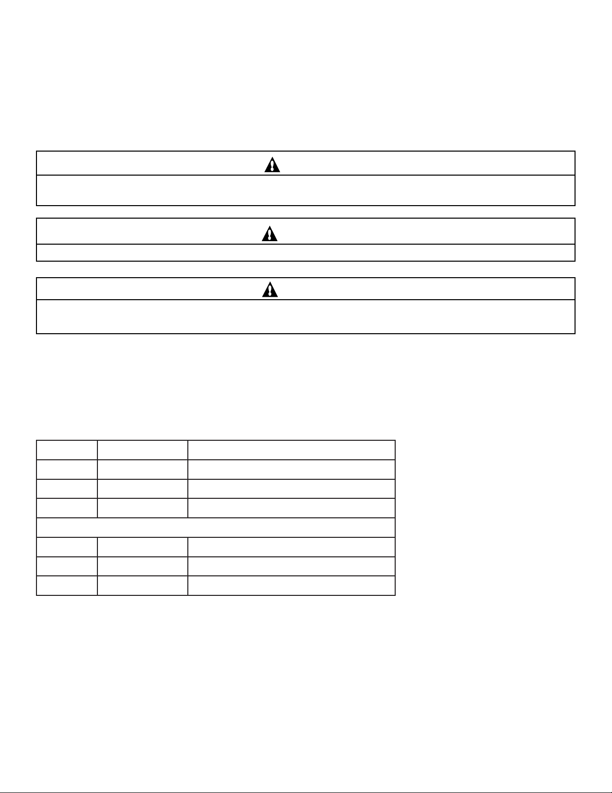
IMPORTANT SAFETY INSTRUCTIONS
READ AND FOLLOW ALL INSTRUCTIONS
CAUTION
All wiring must be performed by a qualified electrician. Basic safety precautions and local codes should always be
followed when installing and using this electrical equipment.
WARNING
To reduce the risk of injury, do not permit children to use this product unless they are closely supervised at all times.
CAUTION
The Hand-held Remote is not waterproof. If it accidentally gets submerged, disassemble by removing screw. Remove
battery and let unit dry out. Reassemble.
SAVE THESE INSTRUCTIONS.
SYSTEM INCLUDES:
EQUIPMENT LOCATION
With the exception of the optional Spa-side Remote Control (which is ETL listed for installation right at the
tile-line of the spa), all equipment must be located five feet or more from the water’s edge.
1. LX-100 RF Power/Load Center at the equipment site.
2. Valve Actuators at valves to be motorized.
N/PrebmuNledoMnoitpircseD
540025TZE001-XL)gnir-odnaannetnahtiw(retneCrewoPFR
540362T42-AVC).ytq2(srotautcAevlaV
810025———).ytq1(etomeRdleh-dnaH
RO
150025LTZE001-XL)gnir-odnaannetnahtiw(retneCdaoLFR
540362T42-AVC).ytq2(srotautcAevlaV
810025———).ytq1(etomeRdleh-dnaH
P/N 520050 6 Rev. F 3-26-04
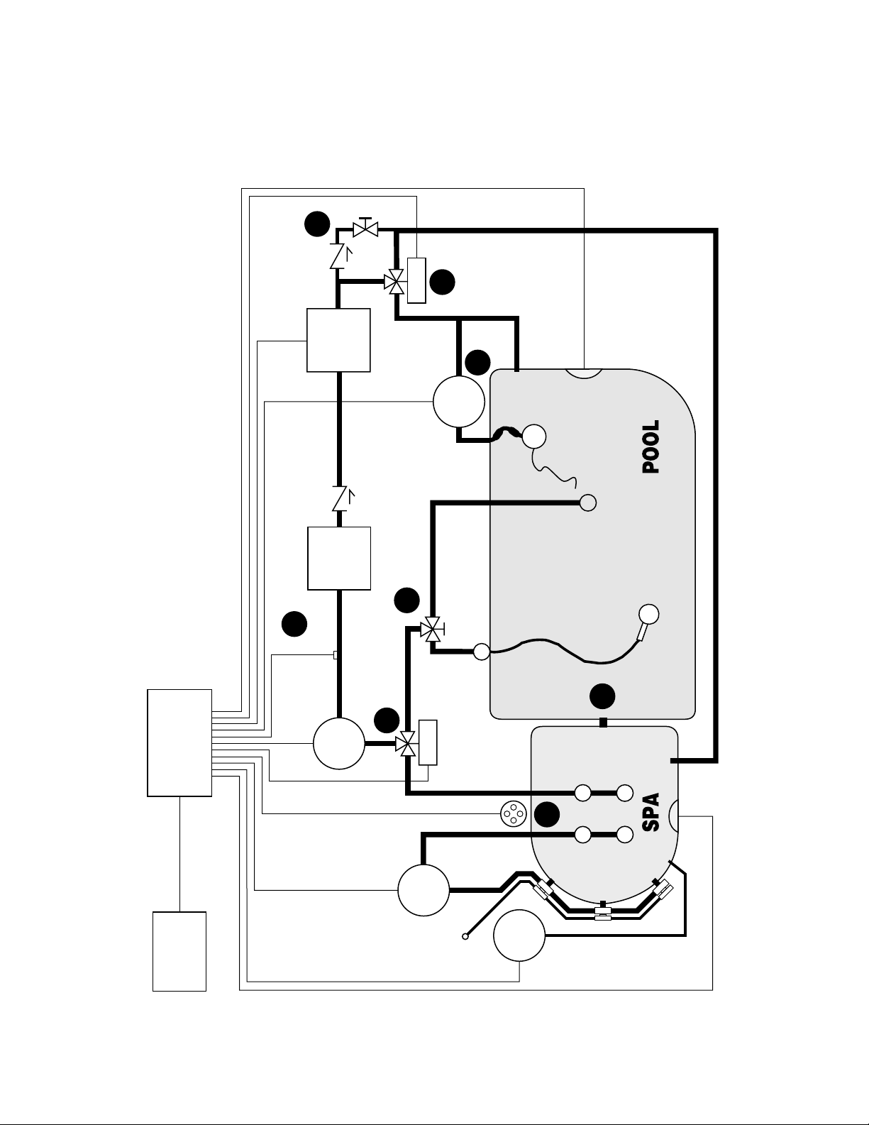
RECOMMENDED HYDRAULIC SCHEMATIC
Refer for “PLUMBING REQUIREMENTS” on page 7.
CP-100
CONTROLLER
(OPTIONAL)
LX-100
RF POWER/LOAD
CENTER
CVA-24
HEATER
WATER
SENSOR
SKIMMER
FILTER
PUMP
FILTER
CVA-24
MAIN
DRAIN
SPA
JET
PUMP
BLOWER
POOL
LIGHT
SPA-SIDE
REMOTE
JET AIR
INTAKE
SPA
LIGHT
5
1
4
6
SUCTION
CLEANER
3
2
9
POOL
CLEANER
PUMP
8

Rev. F 3-26-04 7 P/N 520050
PLUMBING REQUIREMENTS
Plumb system in accordance with “RECOMMENDED HYDRAULIC SCHEMATIC” on page 6, local codes
and the following guidelines.
Bring all lines back to the equipment pad.
1. Spa should be at or above the level of the pool.
If spa is attached to pool, provide a dam between the two bodies of water to allow spa overflow into
pool. If spa is not attached to pool, an overflow, sufficient in size to carry full pump-flow, must be
installed at water level in the spa.
2. Plumb a three-port Intake Valve on the suction-side of the filter pump, so that center port of valve is
connected to the pump inlet.
Connect spa suction to one side of Intake Valve, and pool suction to the other side.
3. Plumb a three-port Return Valve on the return-side of the heater, so that return water will enter valve
through the center port.
Connect spa return to one side of Return Valve, and pool return to the other side.
4. A ½” spa make-up line (incorporating a ½” manual gate or ball valve and, for elevated spas, a ½” check
valve) may be provided to bypass the pool return line. This will enable some of the chemically-balanced
water from the pool to cycle through the spa. The manual valve will allow the amount of bypass to be
adjusted.
5. If the spa is to be constructed in concrete, special provision should be made at this time for the installation
of the optional Spa-side Remote Control.
Select a convenient location in the deck or above water level in the spa wall (where the Spa-side Remote
will not be submerged by the spa water), and install a 6” to 12” length of 1-½” PVC pipe to provide a
receptacle for the Spa-side Remote. The pipe should be level and protrude beyond the finished surface of
the spa. It will be cut back at a later date.
Reduce pipe size down to ½” or ¾” conduit, and run to proposed LX-100 RF Power/Load Center
location at equipment pad. Use sweep elbows for turns.
The Spa-side Remote will not be installed until spa construction is complete.
6. For systems which incorporate a skimmer, it is possible to balance the amount of suction between the
skimmer and main drain for maintenance purposes.
This is easily accomplished by installing a manual three-port mixing valve at the suction line.
Plumb one port to the skimmer and the other to the main drain.
7. If a “non-booster pump” pressure-side pool cleaner is being used, plumb a manual three-port valve
between the filter pump and filter, with the third port plumbed to the pool cleaner line, and install a
motorized two-port Pool Cleaner Valve at this line. The motorized valve will automatically open
whenever the Control System activates the pool cleaner.
8. If a booster pump pool cleaner is being used, plumb the booster pump so that its suction-side is
connected to the pool return, after the heater and as close to the ground as practical.
9. If optional water sensor is used with Cp-100 indoor controller, locate between filter pump and filter.

P/N 520050 8 Rev. F 3-26-04
LX-100 RF POWER/LOAD CENTER
Select a convenient location to mount the LX-100 RF Power/Load Center. Ensure that the location is greater than
5 feet from the water’s edge and no further than 15 feet from any motorized valves (otherwise Valve Actuator cables
will need to be extended). The top of the LX-100 RF Power/Load Center should be a minimum 5 feet above the
ground and a minimum 8 feet from any air blower to optimize RF signal reception.
Mount the LX-100 RF Power/Load Center on a flat surface using appropriate screws through the external mounting
points located on the side of the enclosure. Do not drill and mount from inside the enclosure.
Loosen LOCK SCREW of hinged faceplate in left-side of LX-100 RF Power/Load Center, and swing open to expose
the low-voltage compartment. All low-voltage connections are made to the circuit board, in accordance with wiring
diagram located inside door.
The high-voltage wiring compartment is located behind service panel in right-side of LX-100 RF Power/Load Center.
HIGH VOLTAGE WIRING
GENERAL
If using a LX-100EZT System, install an electrical sub-panel with separate breakers for each load at the equipment site.
Circuit breakers should be readily accessible to the spa user, but installed at least 5 feet from the water’s edge.
If using a LX-100EZTL System, the LX-100 RF Power/Load Center has provisions for breakers.
Make sure that the motor(s) on the equipment have built-in thermal protection.
At the LX-100 RF Power/Load Center, remove the service panel (at right) to expose the high-voltage compartment,
and knock-out the appropriate holes at bottom of enclosure to facilitate conduit mounting. Screw terminals are
provided for high-voltage connections.
SYSTEM POWER
Provide a separate circuit breaker to power the system. Either 115 or 230 VAC can be used (115V is preferable).
System draws less than 1-Amp. The breaker will open all ungrounded supply conductors to comply with section
422-20 of the National Electrical Code, ANSI/NFPA 70-1987.
Run appropriate wires from circuit breaker to high-voltage compartment of LX-100 RF Power/Load Center, and
connect to top terminal block in accordance with wiring label, which is marked SYSTEM POWER.
Install two jumper wires for 115V, or one jumper for 230V, according to wiring label.
EQUIPMENT POWER
Provide independent circuit breakers for R1 (FLTR), R2 (AUX1), R3 (AUX2) and R4 (AUX3).
Run appropriate wires from breakers to high-voltage compartment of LX-100 RF Power/Load Center, and connect to
LINE1 and LINE2 screw terminals at each terminal block.
Connect pumps and other high-voltage equipment to LOAD1 and LOAD2 terminals.
Each individual terminal block can be wired for either 115V or 230VAC.
Note:
For 115V equipment, only half of the terminal block will be used (i.e.: LINE1 and LOAD1).
Rev. F 3-26-04 9 P/N 520050
LOW VOLTAGE CABLES
Install cable between the low voltage compartment of the LX-100 RF Power/Load Center and the various pieces of
equipment. Provide plastic or metallic conduit where cables run underground, through concrete, etc.
Note
Never install low voltage and high voltage wires in the same conduit. It is advisable to maintain a
minimum distance of 12” between parallel runs of low voltage and AC current-carrying wires.
Valve Actuators are provided with 15 feet of 3-conductor cable.
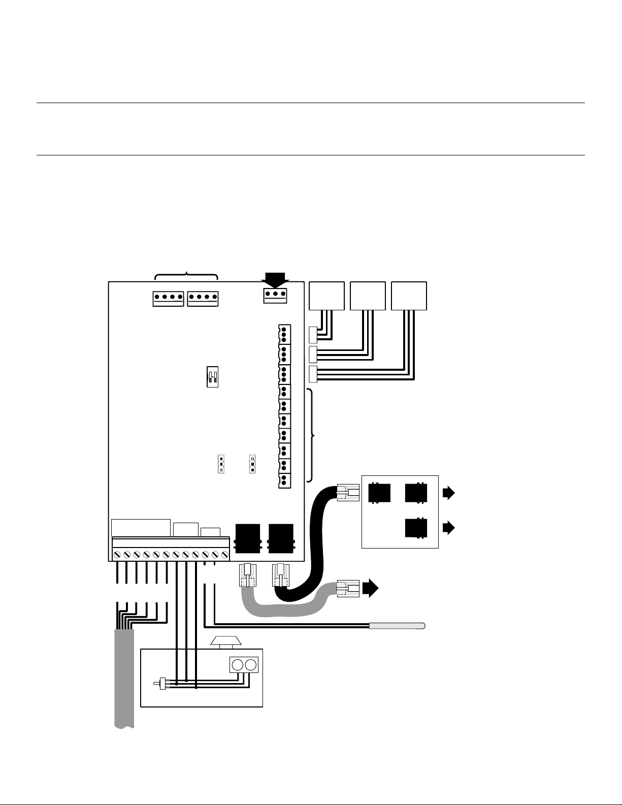
LOW VOLTAGE WIRING
to SPA-SIDE REMOTE (Optional)
INTAKE
VALVE
ACTUATOR ACTUATOR
VALVE
RETURN AUXILIARY
VALVE
ACTUATOR
DUAL THERMOSTAT
GAS HEATER
THERMOSTATS
HIGH
LOW
TRANSFORMER
CONNECTIONS
RELAY CONNECTIONS
DO NOT SHORT THESE PINS
FLTR
SPA
EHTR
AUX3
VLV
AUX1
AUX2
CLNR
AUX
VLV
VLV
RET
24
LX-100/LX-100EZ
WIRING
YES
DELAY
18 0
INT
WTRFL
12
ON
AUX1
NO
MOTOR SWITCH
FLTR TIMER
MOTOR SWITCH
CLNR TIMER
TIMER
CONNECTIONS
SILVER
12
RED
GRN
OFF
LX-100 or LX-100EZ POWER CENTER
BLK
RED
YEL
GRN
BLU
+15
GND
AUX1
SPA
AUX3
AUX2
C
S
P
GAS HTR
SLMP
ORG
REMOTE SWITCHES
YRG
CLNR
AUX VLV
CONTROLLED BY
AUX 3
JP16 JP17
GRN RED
TEMP
SENSOR
WATER TEMPERATURE SENSOR (Optional)
LX-100
EZ-WIRELESS
Cp100
BLU
BLU
to CP-100 or RF RECEIVER BOARD
POWER ISOLATION PCB
BLU
(1)
to RF RECEIVER
BOARD
to CP-100
BLU
P/N 520050 10 Rev. F 3-26-04
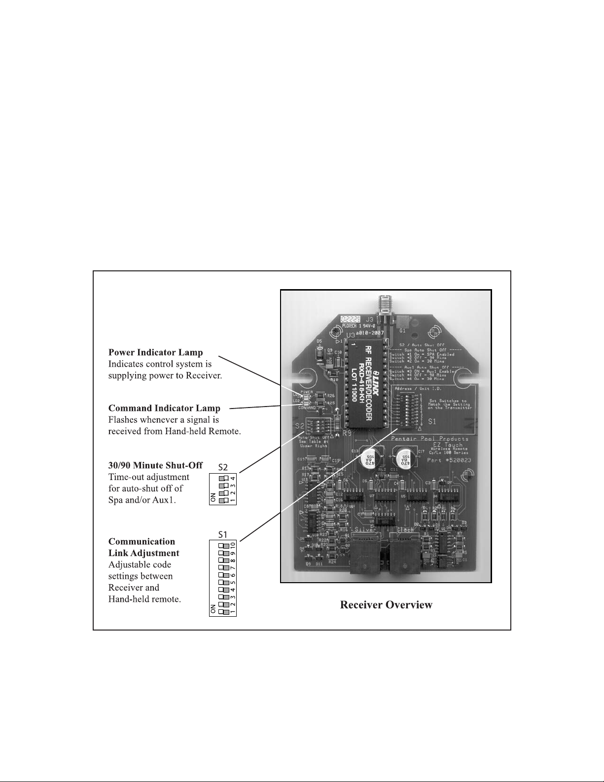
RECEIVER CIRCUIT BOARD
Mounted to the back of the LX-100 RF Power/Load Center is the Receiver Circuit Board.
On the circuit board, you will discover the following:
1. A 4-position configuration switch (designated S2), which can be used to configure an automatic
countdown cycle for the Spa and/or the Aux1 circuit. (Aux1 is designated as button “A” on Hand-held
Remote). See page 13 for details.
2. A 10-position configuration switch (designated S1), which can be used to customize the communication
link between the Receiver and Hand-held Remote.
3. 2-qty. status lights (designated POWER and COMMAND), which are used for trouble-shooting:
POWER: Indicates that the Control System is supplying power to the Receiver unit.
COMMAND: Flashes whenever a button is pushed on the Hand-held Remote.
 Loading...