


POSI-FLO® II FILTERS
O W N E R ’ S M A N U A L
INSTALLATION, OPERATION & PARTS
MODELS
PTM50 PTM70 PTM100 PTM135
Furnish this manual to the end user of this filter; its use will reduce service calls and chance of injury and will lengthen filter life.
Pentair Water Pool and Spa, Inc.
1620 Hawkins Ave., Sanford, NC 27330 • (800) 831-7133 • (919) 566-8000
10951 West Los Angeles Ave., Moorpark, CA 93021 • (800) 831-7133 • (805) 553-5000
Visit us on the Internet @ www.pentairpool.com or www.staritepool.com
© 2009 Pentair Water Pool and Spa, Inc. |
S294 (Rev. A 4/16/09) |

STA-RITE POSI-FLO® II FILTERS:
To avoid unneeded service calls, prevent possible injuries, and get the most out of your filter, READ THIS MANUAL CAREFULLY!
The Sta-Rite Posi-Flo® II Series Filter: |
|
•Is designed to filter water for swimming pools, spas and hot tubs. |
|
•Is an excellent performer; durable, reliable. |
|
Table of Contents |
|
Safety Instructions ....................................................................................... |
3 |
General Information.................................................................................... |
4 |
Installation - General................................................................................... |
5 |
Installation - Assembling Filter.................................................................. |
6-7 |
Startup ........................................................................................................ |
7 |
Filter Disassembly/Assembly .................................................................... |
8-9 |
Filter Cleaning Procedure .......................................................................... |
10 |
Special Cleaning Instructions................................................................ |
10-11 |
Pool Maintenance ................................................................................ |
11-12 |
Winterizing............................................................................................... |
12 |
Troubleshooting Guide.............................................................................. |
13 |
Repair Parts List......................................................................................... |
14 |
Before installing, open filter to make sure internal air bleed tube and air bleed filter (Key Nos. 13 and 14, Page 14) are in place. Clean air bleed periodically.
2
Component Checklist
(See Page 14)
The carton should contain the following:
Filter Assembly
Pressure Gauge
Air Release Valve Assembly
Pressure Gauge Screen
If not, please contact Customer Service at 1-800-831-7133.
READ AND FOLLOW SAFETY INSTRUCTIONS!
This is the safety alert symbol. When you see this symbol on your system
 or in this manual, look for one of the following signal words and be alert to the potential for personal injury.


 warns about hazards that will cause death, serious personal injury, or major property damage if ignored.


 warns about hazards that can cause death, serious personal injury, or major property damage if ignored.


 warns about hazards that will or can cause minor personal injury or property damage if ignored.
NOTICE indicates special instructions not related to hazards.
Carefully read and follow all safety instructions in this manual and on equipment. Keep safety labels in good condition; replace if missing or damaged.


 Incorrectly installed or tested equipment may fail, causing
severe injury or property damage. Have a trained pool professional perform all pressure tests. Read and follow instructions in owner's manual when installing and operating equipment.
1.Do not connect system to a high pressure or city water system.
2.Use equipment only in a pool or spa installation.
3.Trapped air in system can cause explosion. BE SURE all air is out of system before operating or testing equipment.
Before pressure testing, make the following safety checks:
•Check all clamps, bolts, lids, and system accessories before testing.
•Release all air in system before testing.
•Tighten Sta-Rite trap lids to 30 ft. lbs. (4.1 kg-cm) torque for testing.
•Water pressure for test must be less than 25 PSI (172 kPa).
•Water Temperature for test must be less than 100o F. (38o C).
•Limit test to 24 hours. After test, visually check system to be sure it is ready for operation. Remove trap lid and retighten hand tight only.
NOTICE: These parameters apply to Sta-Rite equipment only. For non-Sta-Rite equipment, consult manufacturer.
If filter clamp is adjusted under pressure, tank will blow off of base, causing severe injury or major property damage.
BEFORE WORKING
ON FILTER:
1.Stop pump.
2.Open air release valve.
3.Release all pressure from system.
3

GENERAL INFORMATION


 Hazardous pressure. If filter is improperly disassembled or - assembled, it will explode under pressure. To avoid danger of severe injury or major property damage, always follow service instructions in this manual (Pages 8 to 10) when working on filter.


 Risk of explosion. Never operate this filter system at more than 50 pounds per square inch (50 PSI/345kPa) pressure!
Clean a new pool as well as possible before filling pool and operating filter. Excess dirt and large particles of foreign matter in the system can cause serious damage to the filter and pump.
With a cartridge filter system in place and operating correctly, clean water is returned to the pool faster than the pool water is being contaminated. A typical pool installation will require approximately one week to obtain and maintain the sparkle that your filter is capable of giving you.
Keep pool water pH at recommended level (7.2 to 7.6).
Be sure both clamps are in place and knobs are securely tightened before starting filter.
Maintain pressure gauge in good working order. Replace gauge if it fails or is damaged.
Make sure internal air bleed tube and air bleed filter (Key Nos. 13 and 14, Page 14) are in place before operating filter. Clean air bleed periodically.
Cleaning interval is based on pressure differential, not on length of time filter is operated. Different areas and water conditions will have different normal cleaning intervals.
NOTICE: Some pool disinfectants may clog filter media. To maximize media life and filter cycle time, closely follow disinfectant manufacturer’s instructions when cleaning pool or filter.
On a new pool installation, we recommend:
1.Turn to Page 8 for instructions and disassemble the filter after the initial cleanup.
2.Remove and hose down the element assembly to remove contaminants.
Pressure Drop (PSI)
24
20
16
12
8
4
0
55.0 |
|
|
45.0 |
|
|
35.0 |
(Feet) |
|
25.0 |
Drop |
|
Pressure |
||
15.0 |
||
|
5.0
0
20 |
40 |
60 |
80 |
100 |
120 |
140 |
Flow Rate (G.P.M.)
577 0993
Pressure drop curve for all PTM filters. Find flow on chart and go up until line intersects curve to find pressure drop for your filter.
4
Before installing, open filter to make sure internal air bleed tube and air bleed filter (Key Nos. 13 and 14, Page 14) are in place. Clean air bleed periodically.
 WARNING
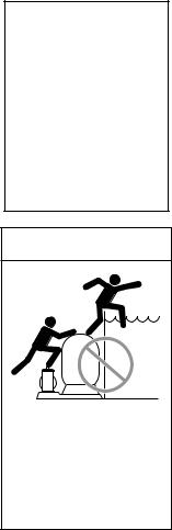
Risk of drowning and falls. Place equipment at least 4 feet from pool so that children cannot
climb over it into pool.
sss
Do not allow children to stand or play on filter or pump.
INSTALLATION - GENERAL
Installation of filter should only be done by qualified, licensed personnel.
Filter mount must
Provide space and lighting for easy access for routine maintenance.
Provide adequate ventilation and drainage for pump.
Be protected from weather and reasonably level.
Be less than three feet above pool water level.
Be as close to pool as possible to reduce line loss from pipe friction.
Piping
All piping must conform to local and state plumbing and sanitary codes.
Never use pipe joint sealing compound on pipe and fittings that are plastic or may come into contact with plastic. To seal threaded connections on PVC pipe and fittings, use only Teflon® tape, Plasto-Joint Stik® or Silastic 732® RTV; pipe joint compound may cause stress cracking of plastic components. Use pipe joint compounds only on metal-to-metal joints.
Support pipe independently to prevent strains on filter or pump.
Use 1-1/2” or 2” pipe to reduce pressure losses.
NOTICE: Filter locations remote from pool are possible but may require larger pipe to produce adequate flow through filter.
Check local codes if considering a remote installation.
Fittings restrict flow; for best efficiency use fewest possible fittings.
Keep piping tight and free of leaks: pump suction line leaks may cause trapped air in filter tank or loss of prime at pump; pump discharge line leaks may show up as dampness or jets of water.
Valves
A check valve installed between pool and filter outlet will prevent contaminants from draining back into pool.
NOTICE: A check valve between filter and pool will also prevent possible backflow which could dislocate element from its seat.
A check valve installed between filter and heater will prevent hot water from heater from backing up into the filter and deforming filter elements.
NOTICE: Damaging filter elements through excessive heat voids the warranty.
Electrical
BE SURE filter grounding and bonding meets local and National Electrical Code standards. All wiring, grounding and bonding of associated equipment must meet local and National Electrical Code standards.
5
 Loading...