

MAX-E-GLAS II
TM
and DURA-GLAS II
TM
CENTRIFUGAL PUMPS
WITH INTEGRAL TRAP
O W N E R’ S M A N U A L
INSTALLATION, OPERATION & PARTS
Series P4E, P4EA, P4R, and P4RA
See Page 2 for Model Numbers
Sta-Rite Pool/Spa Group
293 Wright Street, Delavan, WI 53115
North America: 800-752-0183, FAX 800-582-2217
International: 262-728-5551, FAX: 262-728-4461, TELEX: ITT 4970245
www.sta-ritepool.com
Union City, TN • Delavan, WI • Mississauga, Ont. • Murrieta, CA
© 2002, Sta-Rite Industries, Inc. Printed in U.S.A. S454 (Rev. 12/5/02)
This manual should be furnished to
the end user of this pump; its use will
reduce service calls and chance of
injury and will lengthen pump life.

2
‘P4R’ and ‘P4E’ SERIES II PUMP
WITH TRAP
To avoid unneeded service calls, prevent possible injuries, and get the most
out of your pump, READ THIS MANUAL CAREFULLY!
The Sta-Rite ‘P4R’ and ‘P4E’ Series II Self-priming Centrifugal pumps:
• Are designed for use with swimming pools or as centrifugal pumps.
• Are excellent performers; durable, reliable.
Table of Contents
Safety Instructions ........................................................................................3
Installation.................................................................................................4-6
Electrical....................................................................................................6-8
Operation ................................................................................................9-10
Storage/Winterizing ....................................................................................10
Pump Service.........................................................................................11-12
Troubleshooting Guide ...............................................................................13
Repair Parts List .....................................................................................14-18
Warranty.....................................................................................................19
Max-E-Glas II™
HP
3/4 P4E6D-186L P4E62D-186L P4E6D-186LV
1 P4E6E-187L P4EA6E-186L P4E62E-187L P4E6E-187LV
1-1/2 P4E6F-188L P4EA6F-187L P4E62F-188L P4E6F-188LV
1-3/4 P4EAA6F-198L
2 P4E6G-189L P4EA6G-188L P4E62G-189L P4E6G36-189 P4E6SSG36-189
2 P4E6G-189LV P4EA6G-188LV
2-1/2 P4EAA6G-189L
3 P4E6H-190LV
3 P4E6H-190L P4E62H-190L P4E6H36-190 P4E6SSH36-190
Dura-Glas II™
HP
3/4 P4R62D3-186 P4R6D3-186
1 P4R62E3-187 P4R6E-187L P4RA6E-186L P4R6E3-187
1-1/2 P4R62F3-188 P4R6F-188L P4RA6F-187L P4RA6YF-187L P4R6F3-188
1-3/4 P4RAA6F-198L
2 P4R62G3-189 P4R6G-189L P4RA6G-188L P4R6G3-189
2-1/2 P4RAA6G-189L P4RA6YG-188L
3 P4R6H3-190
3
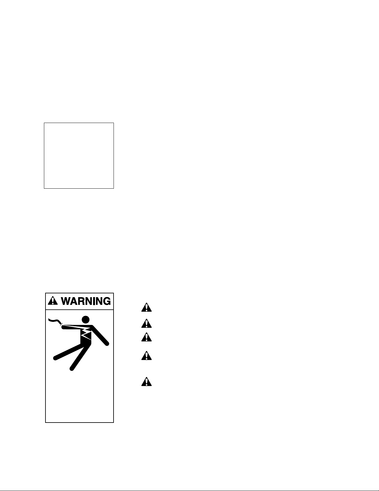
READ AND FOLLOW SAFETY
INSTRUCTIONS!
This is the safety alert symbol. When you see this symbol on your system
or in this manual, look for one of the following signal words and be alert
to the potential for personal injury.
warns about hazards that will cause death, serious personal
injury, or major property damage if ignored.
warns about hazards that can cause death, serious personal
injury, or major property damage if ignored.
warns about hazards that will or can cause minor personal injury
or property damage if ignored.
NOTICE indicates special instructions not related to hazards.
Carefully read and follow all safety instructions in this manual and on equipment. Keep safety labels in good condition; replace if missing or damaged.
Incorrectly installed or tested equipment may fail, causing
severe injury or property damage.
Read and follow instructions in owner's manual when installing
and operating equipment. Have a trained pool professional per-
form all pressure tests.
1. Do not connect system to a high pressure or city water system.
2. Use equipment only in a pool or spa installation.
3. Install pump with at least 2 hydraulically balanced main drains equipped
with correctly installed, screw-fastened, anti-entrapment certified covers.
See Page 5.
4. Trapped air in system can cause explosion. BE SURE all air is out of system
before operating or testing equipment.
Before pressure testing, make the following safety checks:
• Check all clamps, bolts, lids, and system accessories before testing.
• Release all air in system before testing.
• Tighten Sta-Rite trap lids to 30 ft. lbs. (4.1 kg-m) torque for testing.
• Water pressure for test must be less than 25 PSI (7.5 kg/cm
2
).
• Water Temperature for test must be less than 100oF. (38oC).
• Limit test to 24 hours. After test, visually check system to be sure it is ready
for operation. Remove trap lid and retighten hand tight only.
NOTICE: These parameters apply to Sta-Rite equipment only. For
non-Sta-Rite equipment, consult manufacturer.
INSTALLATION
Only qualified, licensed personnel should install pump and wiring.
Pump mount must:
Be located away from corrosive or flammable chemicals.
IMPORTANT
SAFETY
INSTRUCTIONS
Always follow basic safety precautions with this equipment, including the following.
To reduce the risk of
injury, do not permit children to
use this product unless they are
closely supervised at all times.
This pump is for use
with permanently installed pools
and may also be used with hot
tubs and spas if so marked. Do
not use with storable pools. A
permanently installed pool is constructed in or on the ground or in
a building such that it cannot be
readily disassembled for storage.
A storable pool is constructed so
that it may be readily disassembled for storage and reassembled
to its original integrity.
SAVE THESE
INSTRUCTIONS
4
Have enough ventilation to maintain air temperature at less than the maximum
ambient temperature rating (Max. Amb.) listed on the motor model plate. If this
pump is installed in an enclosure/pump house, the enclosure must have adequate ventilation and air circulation to keep the temperature in the enclosure at
or below the motor’s rated ambient temperature whenever the pump is running.
Be solid - Level - Rigid - Vibration free - Non-combustible. (To reduce
vibration and pipe stress, bolt pump to mount.)
Allow pump suction inlet height to be as close to water level as possible.
Allow use of short, direct suction pipe (To reduce friction losses).
Allow for gate valves in suction and discharge piping.
Have adequate floor drainage to prevent flooding.
Be protected from excess moisture.
Allow adequate access for servicing pump and piping.
Fire and burn hazard. Modern motors run at high temperatures.
To reduce the risk of fire, do not allow leaves, debris, or foreign matter to collect around the pump motor. To avoid burns when handling the motor, let it
cool for 20 minutes before trying to work on it.
NOTICE: Use Teflon tape or Plasto-Joint Stik
1
for making all threaded connections to the pump. Do not use pipe dope; pipe dope will cause stress cracking
in the pump.
NOTICE: Pump suction and discharge connections have molded in thread
stops. DO NOT try to screw pipe in beyond these stops.
Teflon Taping Instructions:
Use only new or clean PVC pipe fittings.
Wrap male pipe threads with one to two layers of Teflon tape. Cover entire
threaded portion of pipe.
Do not overtighten or tighten past thread stop in pump port!
If leaks occur, remove pipe, clean off old tape, rewrap with one to two addi-
tional layers of tape and remake the connection.
NOTICE: Support all piping connected with pump!
1
Lake Chemical Co., Chicago, Illinois
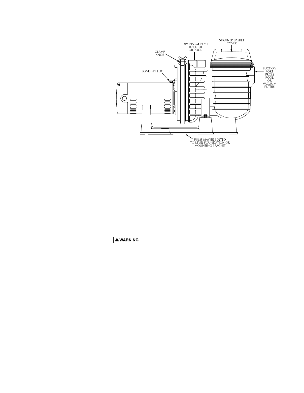
Figure 1
5
Piping:
Use at least 2" IPS PVC (51mm) pipe. Increase size if a long run is needed.
To avoid strains on the pump, support both suction and discharge pipes inde-
pendently. Place these supports near the pump.
To avoid a strain left by a gap at the last connection, start all piping at the
pump and run pipe away from the pump.
Never use a suction pipe smaller than pump suction connection.
To avoid airlocking, slope suction pipe slightly upward toward the pump.
NOTICE: To prevent flooding when removing pump for service, all flooded
suction systems must have gate valves in suction and discharge pipes.
Fittings:
Fittings restrict flow; for best efficiency use fewest possible fittings.
Avoid fittings which could cause an air trap.
Pool fittings must conform to International Association of Plumbing and
Mechanical Officials (IAPMO) standards.
Use only non-entrapping suction fitting or double suction.
POOL PUMP SUCTION
REQUIREMENTS
Pump suction is hazardous and can trap and drown or disembowel bathers. Do not use or operate swimming pools, spas, or hot tubs if a
suction outlet cover is missing, broken, or loose. Follow the guidelines below
for a pump installation which minimizes risk to users of pools, spas, and hot
tubs.
Entrapment Protection
The pump suction system must provide protection against the hazard of
suction entrapment or hair entrapment/entanglement.
Suction Outlet Covers
All suction outlet covers must be maintained. They must be replaced if
cracked, broken, or missing.
See below for outlet cover certification requirements.
All suction outlets must have correctly installed, screw-fastened covers in
place.
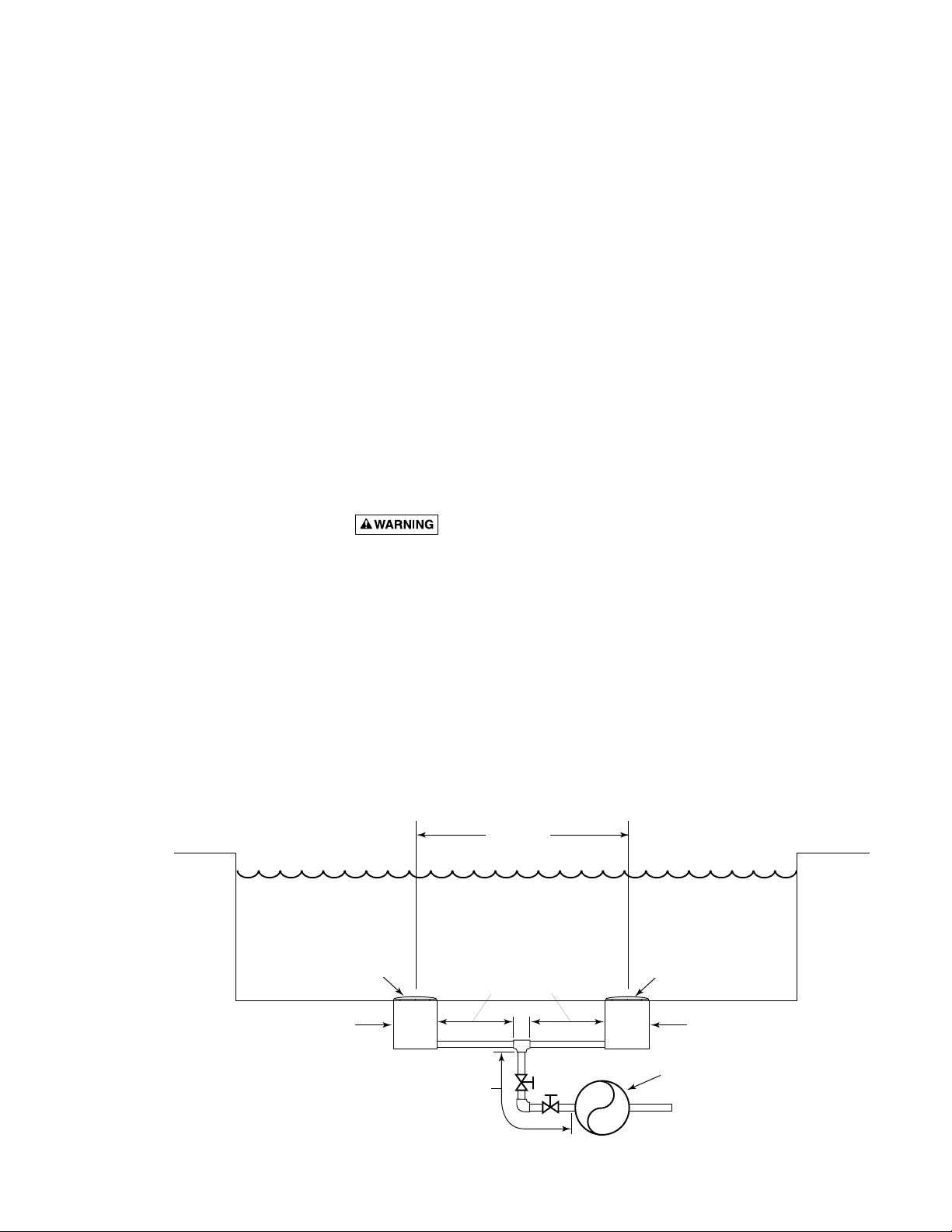
Figure 2 – Recommended pump suction layout.
IAPMO Certified
Anti-entrapment
Cover or Suction Fitting,
screw-fastened to
Main Drain Sump
Suction Outlet
(Main Drain)
Valves OK between
pump and Tee
At Least
3 Feet
No valves between
Tee and Main Drains
IAPMO Certified
Anti-entrapment
Cover or Suction Fitting,
screw-fastened to
Main Drain Sump
Suction Outlet
(Main Drain)
Pump
2762 0197
Hazardous voltage.
Can shock, burn,
or cause death.
Ground pump before
connecting to
power supply.
6
Testing and Certification
Suction outlet covers must have been tested by a nationally recognized testing
laboratory and found to comply with the latest ASME/ANSI Specification for
Suction Fittings For Use in Swimming Pools, Spas, Hot Tubs, and Whirlpool
Bathtub Applications.
Outlets Per Pump
Provide at least two hydraulically balanced main drains, with covers (see Page
5), for each swimming pool pump suction line. The centers of the main drains
(suction fittings) must be at least three feet apart.
The system must be built so that it cannot operate with the pump drawing
water from only one main drain (that is, there must be at least two main drains
connected to the pump whenever it is running). (See Figure 2). However, if
two main drains run into a single suction line, the single suction line may be
equipped with a valve which will shutoff both main drains from the pump
(see Figure 2).
More than one pump can be connected to a single suction line as long as the
requirements above are met.
Water Velocity
The maximum water velocity through any suction outlet must be 1.5 feet per
second unless the outlet complies with the latest ASME/SNSI Specification for
Suction Fittings For Use in Swimming Pools, Spas, Hot Tubs, and Whirlpool
Bathtub Applications. In any case, do not exceed the suction fittings maxi-
mum designed flow rate.
If 100% of the pump’s flow comes from the main drain system, the maximum
water velocity in the pump suction hydraulic system must be six feet per second or less even if one main drain (suction fitting) is completely blocked. The
flow through the remaining main drain(s) must comply with the latest
ASME/ANSI Specification for Suction Fittings For Use in Swimming Pools,
Spas, Hot Tubs, and Whirlpool Bathtub Applications.
ELECTRICAL
Ground motor before connecting to electrical power supply. Failure to
ground motor can cause severe or fatal electrical shock hazard.
Do not ground to a gas supply line.
To avoid dangerous or fatal electrical shock, turn OFF power to motor
before working on electrical connections.
Ground Fault Circuit Interrupter (GFCI) tripping indicates an electrical
problem. If GFCI trips and will not reset, have a qualified electrician
inspect and repair electrical system.
Exactly match supply voltage to nameplate voltage. Incorrect voltage
can cause fire or seriously damage motor and voids warranty.
If in doubt consult a licensed electrician.
Voltage
Voltage at motor must be not more than 10% above or below motor nameplate rated voltage or motor may overheat, causing overload tripping and reduced component life. If voltage is less than 90% or more than 110% of rated
voltage when motor is running at full load, consult power company.
NOTICE: 3 phase
models require magnetic motor starters
and external overload
protection.
If in doubt about the
procedure, consult a
licensed electrician.

7
Grounding/Bonding
Install, ground, bond and wire motor according to local or National Electrical
Code requirements.
Permanently ground motor. Use green ground terminal provided under motor
canopy or access plate (See Figure 3); use size and type wire required by
code. Connect motor ground terminal to electrical service ground.
Bond motor to pool structure. Use a solid copper conductor, size No. 8 AWG
(8.4 sq.mm) or larger. Run wire from external bonding lug (see Figure 3) to
reinforcing rod or mesh.
Connect a No. 8 AWG (8.4 sq.mm) solid copper bonding wire to the pressure
wire connector provided on the motor housing and to all metal parts of the
swimming pool, spa, or hot tub and to all electrical equipment, metal piping
or conduit within 5 feet (1.5 m) of the inside walls of swimming pool, spa, or
hot tub.
Wiring
Pump must be permanently connected to circuit. See Figures 4A, 4B, and 4C
for wiring connection diagrams. Match wire and circuit breaker sizes to correct Fusing and Wiring Data Chart (Page 8). If other lights or appliances are
also on the same circuit, be sure to add their amp loads to pump amp load. (If
unsure how to do this or if this is confusing, consult a licensed electrician.)
Use the load circuit breaker as the master on-off switch.
Install a Ground Fault Circuit Interrupter (GFCI) in circuit; it will sense a shortcircuit to ground and disconnect power before it becomes dangerous to pool
users. For size of GFCI required and test procedures for GFCI, see manufacturer’s instructions.
In case of power outage, check GFCI for tripping (which will prevent normal
water circulation). Reset if necessary.
NOTICE: If you do not use conduit when wiring motor, be sure to seal wire
opening on end of motor to prevent dirt, bugs, etc., from entering motor.
BONDING
Figure 3: Typical ground screw and
bonding lug locations.
Figure 4A: Single-phase, single speed
wiring connection diagram.
For 3-phase connection, refer
to motor nameplate.
Figure 4B: Wiring connections for
plug-in type terminal board
(Single speed, single phase
motors)
Figure 4C: Single-phase, 2-speed wiring hookup diagram
(Models P4RA6YF-187L and P4RA6YG-188L).
LUG
GREEN
GROUND
SCREW
510 0993
Blue
L2
B
230
Volt
Lines
A
L1
White
469 0194A
230 Volt to 115 Volt Conversion. Move plug to change voltage.
230 V
230V
115V
230V
115V
230 Volt to 115 Volt Conversion. Move plug to change voltage.
Pull plug
1.
straight
out from
terminal
board.
230
1.
Volts
115
Volts
A
A
L2
L2
L1
L1
A
L1
115 V
230V
115V
Power Supply
Wires
2.
Plug in again
with arrow
on plug
pointing to
'115 Volts'.
2.
Ground
Screw
A
A
230V
115V
L2
L2
L1
L1
Ground
Screw
230
Volts
A
115
Volts
L1
3962 0401 A
Ground (Green)
Back of
motor
with
Terminal
L2
B
A
Common
Low Spd
Board
L1
High Spd
Power Supply for
Optional Timer.
If using timer, Connect
Timer Motor to Low Speed Only
Minimum switch and timer amp rating must equal Branch Fuse
Rating given in "Recommended Fusing and Wiring Data" table.
Remote
SPDT
Switch
230
Volt
Lines
Circuit
Protector
1168 0794

8
TABLE II - RECOMMENDED FUSING AND WIRING DATA – P4R, P4RA MODELS
Serv. to Motor - Dist. in Ft. (M)
Motor Branch Fuse Max Load Voltage/ 0-100' 101-200' 201-300'
HP Rating Amps* Amps Hz/Phase (0-30 M) (30-60 M) (60-90 M)
P4R Models:
13019.2 115/60/1 10(5.5) 8(8.4) 6(14)
115 9.6 230/60/1 14(2) 14(2) 12(3)
1-1/2 15 12.0 230/60/1 14(2) 14(2) 12(3)
215 11.2 230/60/1 14(2) 14(2) 12(3)
P4RA Models:
1 20/15 15.3/7.6 115/230/60/1 12/14(3/2) 8/14(8.4/2) 6/14(14/2)
1-1/2 30 19.2 115/60/1 10(5.5) 8(8.4) 6(14)
1-1/2 15 9.6 230/60/1 14(2) 14(2) 12(3)
1-3/4 15 12.0 230/60/1 14(2) 14(2) 12(3)
215 12.0 230/60/1 14(2) 14(2) 12(3)
2-1/2 15 11.2 230/60/1 14(2) 14(2) 12(3)
P4RA 2-Speed Models:
1-1/2 - 1/4 15 9.2/2.5 230/60/1 14(2) 14(2) 12(3)
2 - 1/3 15 10.2/3.7 230/60/1 14(2) 14(2) 12(3)
P4R62 Models:
3/4 15 3.8 200/60/3 14(2) 14(2) 14(2)
115 5.6 200/60/3 14(2) 14(2) 14(2)
1-1/2 15 6.6 200/60/3 14(2) 14(2) 14(2)
215 9.8 200/60/3 14(2) 14(2) 14(2)
P4R6 3-Phase Models:
3/4 15/15 3.6/1.8 230/460/60/3 14(2) 14(2) 14(2)
1 15/15 4.7/2.35 230/460/60/3 14(2) 14(2) 14(2)
1-1/2 15/15 5.8/2.9 230/460/60/3 14(2) 14(2) 14(2)
2 15/15 7.0/3.5 230/460/60/3 14(2) 14(2) 14(2)
2-1/2 15/15 9.7/4.9 230/460/60/3 14(2) 14(2) 12(3)/14(2)
3 15/15 11.5/5.8 230/460/60/3 14(2) 14(2) 12(3)/14(2)
* Time delay fuses are recommended instead of standard fuses in any motor circuit.
Wire
Size
AWG
(mm2)
}
Wire
Size
AWG
(mm2)
}
Wire
Size
AWG
(mm2)
}
Wire Size
AWG (mm2)
}
Wire
Size
AWG
(mm2)
}
TABLE I - RECOMMENDED FUSING AND WIRING DATA – P4E, P4EA MODELS
Serv. to Motor - Dist. in Ft. (M)
Motor Branch Fuse Max Load Voltage/ 0-100' 101-200' 201-300'
HP Rating Amps* Amps Hz/Phase (0-30 M) (30-60 M) (60-90 M)
P4E Models:
3/4 20 13.8 115/60/1 12(3) 10(5.5) 8(8.4)
125 16.0 115/60/1 12(3) 8(8.4) 6(14)
115 8.0 230/60/1 14(2) 14(2) 14(2)
1-1/2 15 10.4 230/60/1 14(2) 12(3) 12(3)
215 11.2 230/60/1 14(2) 12(3) 12(3)
215 1.5 575/60/3 14(2) 14(2) 14(2)
315 3.4 575/60/3 14(2) 14(2) 14(2)
325 15.8 230/60/1 12(3) 12(3) 10(5.5)
P4EA Models:
12013.8 115/60/1 12(3) 10(5.5) 8(8.4)
1-1/2 25 16.0 115/60/1 12(3) 8(8.4) 6(14)
115 6.9 230/60/1 14(2) 14(2) 14(2)
1-1/2 15 8.0 230/60/1 14(2) 14(2) 12(3)
1-3/4 15 10.4 230/60/1 14(2) 12(3) 12(3)
215 10.4 230/60/1 14(2) 12(3) 12(3)
2-1/2 15 11.2 230/60/1 14(2) 12(3) 12(3)
P4E62 Models:
3/4 20 13.4 100/60/1 14(2) 12(3) 8(8.4)
3/4 15 6.7 200/60/1 14(2) 14(2) 14(2)
115 7.4 200/60/1 14(2) 14(2) 12(3)
1-1/2 15 10.5 200/60/1 14(2) 12(3) 12(3)
220 14.2 200/60/1 12(3) 12(3) 10(5.5)
325 17.6 200/60/1 10(5.5) 10(5.5) 10(5.5)
* Time delay fuses are recommended instead of standard fuses in any motor circuit.
Wire
Size
AWG
(mm2)
}
Wire
Size
AWG
(mm2)
}
Wire
Size
AWG
(mm2)
}

9
OPERATION
NEVER run pump dry. Running pump dry may damage seals, causing
leakage and flooding. Fill pump with water before starting motor.
Before removing trap cover:
1. STOP PUMP before proceeding.
2. CLOSE GATE VALVES in suction and discharge pipes.
3. RELEASE ALL PRESSURE from pump and piping system.
4. NEVER tighten or loosen clamp while pump is operating!
If pump is being pressure tested, be sure pressure has been released before removing trap cover.
Do not block pump suction. To do so with body may cause severe or
fatal injury. Small children using pool must ALWAYS have close adult
supervision.
Fire and burn hazard. Modern motors run at high temperatures.
To reduce the risk of fire, do not allow leaves, debris, or foreign matter to collect around the pump motor. To avoid burns when handling the motor, let it
cool for 20 minutes before trying to work on it. An automatic internal cutoff
switch protects the motor from heat damage during operation.
NOTICE: Maximum ambient temperature for motor operation must not
exceed maximum ambient temperature rating on motor model plate.
Priming Pump
Release all pressure from filter, pump, and piping system; see the filter owner’s
manual.
In a flooded suction system (water source higher than pump), pump will prime
itself when suction and discharge valves are opened.
If pump is not in a flooded suction system, unscrew and remove trap cover;
fill trap and pump with water.
Do not lubricate the trap cover O-Ring. The original equipment O-Ring contains a permanent internal lubricant.
NOTICE: If you replace the O-Ring with a non-internally lubricated O-Ring,
you may need to apply a silicone based lubricant.
Clean and inspect O-Ring; reinstall on trap cover.
Replace trap cover on trap; turn clockwise to tighten cover.
NOTICE: Tighten trap cover by hand only (no wrenches)! Use a wrench only
if necessary to remove lid!
Pump should prime now. Priming time will depend on vertical length of suction lift and horizontal length of suction piping.
If pump does not prime, make sure that all valves are open, suction pipe end
is under water, and that there are no leaks in suction pipe.
See Troubleshooting Guide, Page 13.
Routine Maintenance
The only routine maintenance needed is inspection/cleaning of trap basket.
Debris or trash that collects in basket will choke off water flow through the
pump. Follow instructions below to clean trap:
1. Stop pump, close valves in suction and discharge, and release all pressure
from system before proceeding.
2. Unscrew trap lid (turn counterclockwise). If necessary, use a lever such as a
board or long screwdriver between lugs on trap cover.
Hazardous suction.
Can trap hair or
body parts, causing
severe injury
or death.
Do not block
suction.

10
3. Remove strainer basket and clean. Be sure all holes in basket are clear,
flush basket with water and replace in trap with large opening at pipe connection port (between ribs provided). If basket is replaced backwards cover
will not fit on trap body.
4. Clean and inspect lid O-Ring; reinstall on trap cover.
5. Clean O-Ring groove on trap body and replace lid. To help keep lid from
sticking, tighten hand tight only (no wrenches!).
6. Prime pump (see priming instructions).
Draining Pump
1. Pump down water level below all inlets to the pool.
To avoid dangerous or fatal electrical shock hazard, turn OFF power to
motor before draining pump.
2. Remove trap cover and use low pressure air to blow accumulated water
from the piping system. Lugs have been provided on the trap lid to use a
lever or pry bar for loosening.
3. Cap inlet piping after draining to keep water out of the pipes.
4. To prevent pump from freezing, remove trap cover and drain the tank body
through the drain plugs (Key No. 19, Pages 14 - 18). Clean pump and trap
basket thoroughly; replace trap cover.
NOTICE: Tighten trap cover by hand only (no wrenches)! Use a lever or
wrench only if necessary to remove cover! If pump is not anchored, use
caution not to break attached piping!
5. Be sure motor is kept dry and covered.
Storage/Winterizing:
Explosion hazard. Purging the system with compressed air can
cause components to explode, with risk of severe injury or death to anyone
nearby. Use only a low pressure (below 5 PSI), high volume blower when air
purging the pump, filter, or piping.
NOTICE: Allowing pump to freeze will damage pump and void warranty!
NOTICE: Do not use anti-freeze solutions (except propylene glycol) in your
pool/spa system. Propylene glycol is non-toxic and will not damage plastic
system components; other anti-freezes are highly toxic and may damage plastic components in the system.
Drain all water from pump and piping when expecting freezing temperatures
or when storing pump for a long time (see instructions below).
Keep motor dry and covered during storage.
To avoid condensation/corrosion problems, do not cover pump with plastic.
For outdoor/unprotected installations:
1. Gravity drain system as far as possible.
2. Protect areas which retain water with non-toxic propylene glycol antifreeze
(“RV antifreeze”).
3. Enclose entire system in a weatherproof enclosure.
4. To avoid condensation/corrosion damage, allow ventilation; do not wrap
system in plastic.
5. Use a 40% propylene glycol/60% water solution to protect pump to -50°F
(-46°C).
Hazardous voltage.
Can shock, burn,
or cause death.
Disconnect power
before working
on pump or motor.

11
Startup For Winterized Equipment
1. Remove any temporary weather protection placed around system.
2. Follow filter manufacturer’s instructions for reactivation of the filter.
3. Inspect all electrical wiring for damage or deterioration over the shutdown
period. Have a qualified serviceman repair wiring as needed.
4. Inspect and tighten all watertight connections.
5. Open all valves in suction and return piping.
6. Remove any winterizing plugs in piping system.
7. Drain all antifreeze from system.
8. Close all drain valves and replace all drain plugs in piping system.
9. Prime pump according to instructions on Page 9.
PUMP SERVICE
Pump should only be serviced by qualified personnel.
For best results, use only genuine Sta-Rite factory parts.
Be sure to prime pump (Page 9) before starting.
Before removing clamp or trap cover:
1. STOP PUMP before proceeding.
2. CLOSE GATE VALVES in suction and discharge pipes.
3. RELEASE ALL PRESSURE from pump and piping system.
4. NEVER tighten or loosen clamp while pump is operating!
To avoid dangerous or fatal electrical shock hazard, turn OFF power to
motor before working on pump or motor.
Aside from lubricating trap cover “O” Ring, no lubrication or regular maintenance is needed beyond reasonable care and periodic cleaning of strainer
basket.
If shaft seal is worn or damaged, repair as follows:
Pump Disassembly/Removing Old Seal
Disconnect power to pump motor.
Be sure gate valves on suction and return piping are closed before start-
ing work.
Release all pressure by opening all vents before starting work.
1. Drain pump by removing drain plugs on bottom of pump body and trap
body.
2. Be sure there is no pressure in trap body; remove cover (unscrew by turn-
ing counterclockwise).
3. Remove clamp holding pump halves together. Motor and seal plate assembly can now be pulled away from pump body.
4. Remove five screws and washers holding diffuser to seal plate. Remove
diffuser.
5. Remove motor canopy. Being careful not to touch capacitor terminals,
loosen capacitor clamp and move capacitor to one side.
6. Hold shaft with 7/16" open-end wrench on motor shaft flats.
Hazardous voltage.
Can shock, burn,
or cause death.
Disconnect power
before working
on pump or motor.

12
7. Unscrew impeller from shaft (turn counterclockwise when facing it).
NOTICE: On models with impeller screw: Remove impeller screw
(left hand thread - turn clockwise) and gasket before removing impeller.
Inspect gasket for damage, cracks, etc. Replace if damaged.
8. Pull rotating member of seal off of impeller sleeve; clean sleeve.
9. Remove four screws holding seal plate to motor.
10. Place seal plate face down on flat surface and tap out ceramic seat.
11. Clean seal cavity in seal plate and clean motor shaft.
Pump Reassembly/Installing New Seal
1. Ceramic seat must be clean and free of dirt, grease, dust, etc. Wet outer
edge of rubber cup on ceramic seat with small amount of liquid detergent; press ceramic seat into seal plate insert firmly and squarely with finger pressure (Figure 5).
2. If ceramic seat will not locate properly, remove it, place face up on bench
and reclean cavity. Ceramic seat should now locate.
3. If seat still will not locate properly, place a cardboard washer over the
polished face and use a piece of 3/4" (19mm) standard pipe for pressing
purposes. NOTICE: Be sure not to scratch or mar polished surface or seal
will leak.
4. Remount seal plate on motor. Tighten bolts to 60-80 inch-lbs.
(69-92 kg/cm) torque.
5. Apply a small amount of liquid detergent to inside diameter of rotating
half of seal.
6. Slide rotating seal member, polished face last, over impeller sleeve until
rubber drive ring hits shoulder.
NOTICE: Be sure not to nick or scratch polished seal face; seal will leak if
face is damaged.
7. Screw impeller onto shaft (clockwise); this will automatically locate seal in
seal plate.
NOTICE: On models with impeller screw: Install impeller gasket and lock
screw (left-hand thread - turn counterclockwise). Torque lock screw to
50-55 inch-lbs. (57.6-63 kg/cm).
8. Mount diffuser on seal plate; tighten screws to 10-14 inch-lbs. (11.2-16.1
kg/cm) torque.
9. Assemble motor and seal plate to volute; be sure clamp is properly
seated.
NOTICE: Clamp knob can be located in any position around volute; if it
is moved after assembly, tighten knob while tapping around clamp to assist sealing. Do not move clamp while pump is full of water.
Hazardous pressure. Release all pressure from pump and
piping system before working on pump or attempting to adjust or remove clamp. Clamp may blow off of pump if adjusted under pressure.
10. Prime pump according to instructions on Page 9.
477 0194NF
Figure 5: Press seal into heat sink in
seal plate

13
TROUBLESHOOTING GUIDE
Read and understand safety and operating instructions in this manual
before doing any work on pump!
Only qualified personnel should electrically test pump motor!
FAILURE TO PUMP; REDUCED CAPACITY OR DISCHARGE PRESSURE
Suction leaks/lost prime:
1. Pump must be primed; make sure that pump volute and trap are full of
water. See priming instructions, Page 9.
2. Make sure there are no leaks in suction piping.
3. Make sure suction pipe inlet is well below the water level to prevent
pump from sucking air.
4. Suction lift of 10 to 20 feet (3-6 M) will reduce performance. Suction lift of
more than 20 feet (6 M) will prevent pumping and cause pump to lose
prime. In either case, move pump closer (vertically) to water source.
Make sure suction pipe is large enough.
Clogged pipe/trap/impeller, worn impeller:
5. Make sure suction trap is not clogged; if it is, clean trap and strainer.
6. Make sure impeller is not clogged (follow steps 1 through 7 under
“Removing Old Seal”, Page 11; check impeller for clogging; follow steps
7 through 10 under “Installing New Seal”, Page 12, for reassembly).
7. Impeller and diffuser may be worn. If so, order replacement parts from
Repair Parts List, Pages 14-18.
8. Pump may be trying to push too high a column of water. If so, a “higher
head” pump is needed.
Electrical:
9. Pump may be running too slowly; check voltage at motor terminals and at
meter while pump is running. If low, see wiring instructions or consult
power company. Check for loose connections.
10. Pump may be too hot.
A. Check line voltage; if less than 90% or more than 110% of rated volt-
age consult a licensed electrician.
B. Increase ventilation.
C. Reduce ambient temperature.
D. Tighten any loose connections.
MECHANICAL TROUBLES AND NOISE
1. If suction and discharge piping are not adequately supported, pump assembly will be strained. See “Installation”, Page 4.
2. Do not mount pump on a wooden platform! Securely mount on concrete
platform for quietest performance.
Hazardous voltage.
Can shock, burn,
or cause death.
Disconnect power
before working
on pump or motor.

14
1
1860 0795
5
6
11
12
13
16
17
18
19
15
14
10
10A
7
8
9
3
4
2
2A
20
22
23
24
21
P4E, P4EA and P4E62 SERIES
MAX-E-GLAS II POOL PUMP
3/4 through 3 HP Models

15
P4E, P4EA and P4E62 SERIES
MAX-E-GLAS II POOL PUMP
3/4 through 3 HP Models
Motor No. Impeller Diffuser
Model No. HP (Key No. 1) (Key No. 10) (Key No. 11)
115/230 Volt
P4E6D-186L 3/4 AE100DHL C105-238P C1-271P1
P4E6E-187L 1 AE100EHL C105-238PB C1-271P1
P4EA6E-186L 1 AE100ELL C105-238P C1-271P1
P4EA6F-187L 1-1/2 AE100FLL C105-238PB C1-271P1
230 Volt
P4E6F-188L* 1-1/2 AE100FHL C105-238PDBA C1-271P
P4EAA6F-198L* 1-3/4 AE100F5LL C105-238PDCA C1-271P
P4E6G-189L* 2 AE100GHL C105-238PEBA C1-271P
P4EA6G-188L* 2 AE100GLL C105-238PDBA C1-271P
P4EAA6G-189L* 2-1/2 AE100G5LL C105-238PEBA C1-271P
P4E6H-190L* 3 AE100HLL C105-238PLA C1-271P
100/200 Volt
P4E62D-186L 3/4 AE100DH2 C105-238P C1-271P1
200 Volt
P4E62E-187L 1 AE100EH2 C105-238PB C1-271P1
P4E62F-188L* 1-1/2 AE100FH2 C105-238PDBA C1-271P
P4E62G-189L* 2 AE100GH2 C105-238PEBA C1-271P
P4E62H-190L* 3 AE100GHL2 C105-238PLA C1-271P
575 Volt
P4E6G36-189* 2 62003-2087 C105-238PEBA C1-271P
P4E6SSG36-189* 2 62003-2087 C105-238PEBA C1-271PSS
P4E6H36-190* 3 62001-1021 C105-238PLA C1-271P
P4E6SSH36-190* 3 62001-1021 C105-238PLA C1-271PSS
Models with “LV” suffix are identical to corresponding models with “L”
suffix except for the shaft seal, which is Viton equipped.
Parts are common to all models listed except as noted;
Key Nos. 1, Motor; 10, Impeller; and 11, Diffuser are listed below.
Key Part Part
No. Description Qty. No.
1 Motor 1 Chart at Right
2 #10-32x1/2” Screw 1 U30-692SS
2A Lock Washer 1 U43-22SS
3 Bonding Lug 1 U17-568
4 Water Slinger 1 17351-0009
5 Seal Plate Kit
(Incl. Key Nos. 6, 7)# 1 C203-194P
6 O-Ring 1 U9-228A
7 Shaft Seal† 1 37400-0027S
8 Clamp Knob 1 C19-37A
9 Clamp 1 WC36-22
10 Impeller 1 Chart at Right
10A Impeller Screw Assembly 1 17301-0151
11 Diffuser 1 Chart at Right
12 Diffuser O-Ring 1 U9-374
13 #8 Lock Washer 5 U43-21SS
14 Screw (w/C1-271P Diffuser) 5 U30-922SS
14 Screw (w/C1-271P1 Diffuser) 5 U30-542SS
15 Tank Body 1 C176-59P
16 Trap Cover 1 C3-185P
17 Trap O-Ring 1 U9-375
18 Basket 1 C8-58P
19 1/4” NPT Drain Plug 2 U178-920P
20 Base Screw 2 U30-918SS
21 Base Washer 2 U43-41SS
22 Base w/Motor Pad** 1 C104-78P
23 Motor Pad 1 C35-43
24 3/8-16x1” Hex Hd. Screw 4 U30-74SS
• Voltage Sticker - 230 Volts
(Single voltage models only) U27-68
• Voltage Sticker - 115/230 Volts
(Dual voltage models only) U27-153
• Tag, “CAUTION, WARNING
(bonding)” 61002-0002
• Decal, “Do not overtighten...” U27-644
• Nameplate (P4E Series) 32155-4035
• Nameplate (P4EA Series) 32155-4071
REPAIR PARTS LIST
*Uses Impeller Screw No. 37337-6080. See Repair Parts List.
• Not illustrated.
** Models P4E6H and P4E62H use Base No. C104-79P and
Motor Pad No. C35-44.
# Models P4E6SSG36-189 and P4E6SSH36-190 use
Part No. C203-194SS.
† Models with “LV” suffix use Part No. 37400-0028S.

16
1860 0795 NL
Key Part Part
No. Description Qty. No.
1 Motor 1 Chart at Right
2 Water Slinger 1 17351-0009
3 Seal Plate (includes Key Nos. 4 and 5) 1 C203-194P
4 “O” Ring 1 U9-228A
5 Shaft Seal 1 37400-0027S
6 Clamp Knob 1 C19-37A
7 Clamp 1 WC36-22
8 Impeller 1 Chart at Right
8A Impeller Screw Assembly 1 17301-0151
9 Diffuser* 1 C1-271P1
10 Diffuser “O” Ring 1 U9-374
11 #8 Lock Washer 5 U43-21SS
12 Screw** 5 U30-922SS
13 Tank Body 1 C176-59P
14 Trap Cover 1 C3-185P
15 Trap “O” Ring 1 U9-375
16 Basket 1 C8-58P
17 1/4” NPT Drain Plug 2 U178-920P
18 Base Screw 2 U30-918SS
19 Base Washer 2 U43-41SS
20 Base w/Motor Pad 1 C104-78P
21 Motor Pad 1 C35-43
22 3/8-16 x 1” Hex Head Screw 4 U30-74SS
• Decal “Suitable for outdoor use . . .” U27-635
• Voltage Sticker - 230 Volts U27-68
• Voltage Sticker - 115/230 Volts U27-153
• Tag, “CAUTION” 61002-0002
• Tag, “CAUTION, WARNING (Bonding) C63-12
• Nameplate*** U33-174
P4R and P4RA SERIES
DURA-GLAS II POOL PUMP
1 through 2-1/2 H.P. Models
• Not illustrated.
* Models P4R6E, P4RA6E, P4RA6F and P4RA6YF use Part No. C1-271P1.
** Model P4R6E, P4RA6E, P4RA6F and P4RA6YF use Part No. U30-542SS.
*** Model P4R6E use Part No. 32155-4071.
REPAIR PARTS LIST
Motor No. Impeller No.
Model No. HP (Key No. 1) (Key No. 10)
115/230 Volt
P4RA6E-186L 1 A100ELL C105-238P
P4R6E-187L 1 A100EHL C105-238PB
P4RA6F-187L 1-1/2 A100FLL C105-238PB
230 Volt
P4R6F-188L 1-1/2 A100FHL C105-238PDBA*
P4RAA6F-198L 1-3/4 A100F5LL C105-238PDCA**
P4R6G-189L 2 AE100GHL C105-238PEBA*
P4RA6G-188L 2 A100GHL C105-238PDBA*
P4RAA6G-189L 2-1/2 AE100G5LL C105-238PEBA*
230 Volt
2-Speed
P4RA6YF-187L 1-1/2 A100FLL-Y C105-238PB
P4RA6YG-188L 2 AE100GLL-Y C105-238PDBA
Parts are common to all models listed except as noted;
Key Nos. 1, Motor; and 10, Impeller are listed below.
*Uses #17301-0151 impeller screw assembly.
** Uses #37337-6080 impeller screw.
22
1
2
3
4
6
7
5
8
8A
21
11
12
18
19
14
15
9
10
13
16
17
20

17
1860 0795
Key Part Part
No. Description Qty. No.
1 Motor 1 Chart at Right
2 #10-32 x 1/2” Screw 1 U30-692SS
2A Lock Washer 1 U43-22SS
3Bonding Lug(#) 1 U17-568
4 Water Slinger 1 17351-0009
5 Seal Plate (includes Key Nos. 6 and 7) 1 C203-194P
6 “O” Ring 1 U9-228A
7 Shaft Seal 1 37400-0027S
8 Clamp 1 C19-37A
9 Clamp Knob 1 WC36-22
10 Impeller 1 Chart at Right
10A Impeller Screw Assembly* 1 17301-0151
11 Diffuser** 1 C1-271P
12 Diffuser “O” Ring 1 U9-374
13 #8 Lock Washer 5 U43-21SS
14 Screw† 5 U30-922SS
15 Tank Body 1 C176-59P
16 Trap Cover 1 C3-185P
17 Trap “O” Ring 1 U9-375
18 Basket 1 C8-58P
19 1/4” NPT Drain Plug 2 U178-920P
20 Base Screw 2 U30-918SS
21 Base Washer 2 U43-41SS
22 Base w/Motor Pad*** 1 C104-78P
23 Motor Pad*** 1 C35-43
24 3/8-16 x 1” Hex Head Screw 4 U30-74SS
• Decal “Suitable for outdoor use . . .” U27-635
• Tag, “CAUTION” 61002-0002
• Tag, “CAUTION, WARNING (Bonding) C63-12
•Nameplate U33-174
P4R SERIES
DURA-GLAS II POOL PUMP
208-230/460V 3 Phase Models
• Not illustrated.
* Model P4R6E3 uses Part No. 17301-0152.
** Models P4R6D3 and P4R6E3 use Part No. C1-271P1.
# Model P4R6H3-190 has no bonding lug assembly, Key Numbers, 2, 2A and 3.
REPAIR PARTS LIST
Motor No. Impeller No.
Model No. HP (Key No. 1) (Key No. 10)
208-230/460-3Ø
P4R6D3-186 3/4 AP100DH C105-238PA
P4R6E3-187 1 AP100EH C105-238PBA
P4R6F3-188 1-1/2 AP100FH C105-238PDBA
P4R6G3-189 2 AP100GH C105-238PEBA
230/460-3Ø
P4R6H3-190 3 AP100HL C105-238PLA
Parts are common to all models listed except as noted;
Key Nos. 1, Motor; and 10, Impeller are listed below.
*** Model P4R6H3 uses Base No. C104-79P and
Pad No. C35-44.
† Models P4R6D3 and P4R6E3 use Part No. U30-542SS.
Models
P4R6D3-186
P4R6E3-187
P4R6F3-188
P4R6G3-189
P4R6H3-190
2A
1
24
3
2
4
5
6
7
8
9
10
16
17
10A
23
13
22
11
12
14
20
21
15
18
19

18
1860 0795
Key Part Part
No. Description Qty. No.
1 Motor 1 Chart at Right
2 #10-32 x 1/2” Screw 1 U30-856ZP
2A Lock Washer 1 U43-22SS
3 Bonding Lug 1 U17-568
4 Water Slinger 1 17351-0009
5 Seal Plate (includes Key Nos. 6 and 7) 1 C203-194P
6 “O” Ring 1 U9-228A
7 Shaft Seal 1 37400-0027S
8 Clamp Knob 1 C19-37A
9 Clamp 1 WC36-22
10 Impeller 1 Chart at Right
10A Impeller Screw Assembly* 1 17301-0151
11 Diffuser** 1 C1-271P
12 “O” Ring Diffuser 1 U9-374
13 #8 Lock Washer 5 U43-21SS
14 Screw*** 5 U30-922SS
15 Tank Body 1 C176-59P
16 Trap Cover 1 C3-185P
17 Trap “O” Ring 1 U9-375
18 Basket 1 C8-58P
19 1/4” NPT Drain Plug 2 U178-920P
20 Base Screw 2 U30-918SS
21 Base Washer 2 U43-41SS
22 Base w/Motor Pad 1 C104-78P
23 Motor Pad 1 C35-43
24 3/8-16 x 1” Hex Head Screw 4 U30-74SS
• Decal “Suitable for outdoor use . . .” U27-635
• Tag, “CAUTION” 61002-0002
• Tag, “CAUTION, WARNING (Bonding) C63-12
•Nameplate U33-174
P4R SERIES
DURA-GLAS II POOL PUMP
200/400V 3 Phase Models
• Not illustrated.
* Model P4R62E3-151 uses Part No. 17301-0152.
** Models P4R62D3, P4R62E3 use Part No. C1-271P1.
*** Models P4R62D3-150 and P4R62E3-151 use Part No. U30-542SS.
REPAIR PARTS LIST
Motor No. Impeller No.
Model No. HP (Key No. 1) (Key No. 10)
200/400V-3Ø
P4R62D3-186L 3/4 AP100DH2 C105-238PA
P4R62E3-187 1 AP100EH2 C105-238PBA
P4R62F3-188 1-1/2 AP100FH2 C105-238PDBA
P4R62G3-189 2 AP100GH2 C105-238PEBA
Parts are common to all models listed except as noted;
Key Nos. 1, Motor; and 10, Impeller are listed below.
Models
P4R62D3-186
P4R62E3-187
P4R62F3-188
P4R62G3-189
2A
1
24
3
2
4
5
6
7
8
9
10
16
17
10A
23
13
22
11
12
14
20
21
15
18
19

▲ Retain Warranty Certificate (upper portion) in a safe and convenient location for your records.
DETACH HERE: Fill out bottom portion completely and mail within 10 days of purchase/installation to:
▼ Sta-Rite, Attn: Warranty Dept., 293 Wright St., Delavan, WI 53115
Pumps, filters, skimmers, underwater lights (except bulbs),
accessories and fittings manufactured by Sta-Rite are warranted to be free of defects in material and workmanship for
one (1) year from date of installation.
Product specific warranties:
Year from date
of installation
HRPB, DEPB, System 3, System 2 and Posi-Clear
Tanks . . . . . . . . . . . . . . . . . . . . . . . . . . . . . . . . . .10 years
Internal filter components and valves . . . . . . . . . 1 year
Max-E-Therm – Pool/Spa Heaters . . . . . . . . . . . . . 2 years
Heater Enclosure only (Upper RH & LH;
lower enclosure; and control board enclosure)… 10 years
Automatic Pool Cleaners including Hose . . . . . . . 2 years
Cristal-Flo filters – Tanks . . . . . . . . . . . .10 years pro-rated*
Valve and internal components. . . . . . . . . . . . . . . 1 year
Posi-Flo II – Tanks . . . . . . . . . . . . . . . . . . . . . . . . .10 years
Elements . . . . . . . . . . . . . . . . . . . . . . . . . . . . . . . . 1 year
PRC Cartridge –
Filter Tanks . . . . . . . . . .5 years pro-rated (1st 2 years full)
Elements . . . . . . . . . . . . . . . . . . . . . . . . . . . . . . . . 1 year
System 2 Above Ground Systems – Tanks . . . . . . .10 years
Pumps / Platform and Internals . . . . . . . . . . . . . . . 1 year
Pumps . . . . . . . . . . . . . . . . . . . . . . . . . . . . . . . . . . . . . 1 year
When equipped with A.O. Smith
2-compartment motors (Does not include
pumps sold as part of a systems package) . . . . . . 2 years
Traps / In-Line Strainers . . . . . . . . . . . . . . . . . . . . . 1 year
Vertical Commercial Filter – Tanks . . . . . . . . . . . .10 years
Internals . . . . . . . . . . . . . . . . . . . . . . . . . . . . . . . . . 1 year
Horizontal Commercial Filter
Tanks . . . . . . . . . . . . . . . . . . . . . . . . . . . . . . . . . . .5 years
(Years 6-9, Prorated declining 20%/year, Yr. 10 - 10%)
Internals . . . . . . . . . . . . . . . . . . . . . . . . . . . . . . . . . 1 year
* Full warranty coverage is in effect for one year after installation. The pro-rated warranty covers the tank only during
the 2nd through 10th year after installation. The amount covered decreases by 10% each year. (ie., 2nd year 90% covered,
3rd year 80% covered, etc.).
The foregoing warranties relate to the original consumer purchaser (“Purchaser”) only. Sta-Rite shall have the option to repair or replace the defective product, at its sole discre-
tion. Purchasers must pay all labor and shipping charges necessary to replace the product covered by this warranty.
Requests for warranty service must be made through the installing dealer. This warranty shall not apply to any product
that has been subject to negligence, misapplication, improper
installation or maintenance, or other circumstances which are
not in Sta-Rite’s direct control.
This warranty sets forth Sta-Rite’s sole obligation and
Purchaser’s exclusive remedy for defective products.
STA-RITE SHALL NOT BE LIABLE FOR ANY CONSEQUENTIAL,
INCIDENTAL OR CONTINGENT DAMAGES WHATSOEVER.
THE FOREGOING WARRANTIES ARE EXCLUSIVE AND IN
LIEU OF ALL OTHER EXPRESS WARRANTIES. IMPLIED WARRANTIES, INCLUDING BUT NOT LIMITED TO THE IMPLIED
WARRANTIES OF MERCHANTABILITY AND FITNESS FOR A
PARTICULAR PURPOSE, SHALL NOT EXTEND BEYOND THE
DURATION OF THE APPLICABLE EXPRESS WARRANTIES
PROVIDED HEREIN.
Some states do not allow the exclusion or limitation of incidental or consequential damages or limitations on how long
an implied warranty lasts, so the above limitations or exclusion may not apply to you. This warranty gives you specific
legal rights and you may also have other rights which vary
from state to state.
Supersedes all previous publications.
Sta-Rite Industries, Inc.,
293 Wright St., Delavan, WI 53115
Warranty Registration Card
Name
Address
City State Zip
Purchase Date
Product Purchased
■■ New installation ■■ Replacement
Type of Pool ■■ Inground ■■ Vinyl ■■ Fiberglass ■■ Gunite
Size of Pool
Years pool has been in service ■■ less than 1 ■■ 1-3 ■■ 3-5 ■■ 5-10
Purchased from:
Company name
Address
City State Zip
Please send me more information on these
other products from Sta-Rite.
■■ Pumps ■■ Filters ■■ Automatic Pool Cleaners
■■ Maintenance Equipment ■■ Test Strips
■■ Heaters
S4877PS (Rev. 2/4/03)
STA-RITE LIMITED WARRANTY

 Loading...