


293 Wright Street, Delavan, WI 53115
Phone: 1-888-782-7483 Fax: 1-800-426-9446 Web Site: pumps.com
OWNER’S MANUAL
Shallow Well Jet Pumps/
Tank Systems
MANUAL DEL USUARIO
Sistemas de bombas tip “jet”/ tanques para pozos poco profundos
“PN” Series |
Installation/Operation/Parts
For further operating, installation, or maintenance assistance:
Call 1-888-782-7483
English . . . . . . . . . . . Pages 2-11
“FN” / “FSN” Series |
Instalación/Operación/Piezas
Para mayor información sobre el funcionamiento, instalación o mantenimiento de la bomba:
Llame al 1-888-782-7483 Español . . . . . . . Paginas 12-20
© 2011 |
S919 (1/20/11) |

Safety |
2 |
|
|
Important Safety Instructions
SAVE THESE INSTRUCTIONS - This manual contains important instructions that should be followed during installation, operation, and maintenance of the product. Save this manual for future reference.
 This is the safety alert symbol. When you see this symbol on your pump or in this manual, look for one of the following signal words and be alert to the potential for personal injury!
 indicates a hazard which, if not avoided, will result in death or serious injury.


 indicates a hazard which, if not avoided, could result in death or serious injury.
 indicates a hazard which, if not avoided, could result in minor or moderate injury.
NOTICE addresses practices not related to personal injury.
Carefully read and follow all safety instructions in this manual and on pump..
Keep safety labels in good condition. Replace missing or damaged safety labels.
 WARNING
Hazardous voltage. Can shock, burn, or cause death.
Ground pump before connecting to power supply. Disconnect power before working on pump, motor or tank.
Wire motor for correct voltage.. See “Electrical” section of this manual and motor nameplate..
Ground motor before connecting to power supply..
Meet National Electrical Code, Canadian Electrical Code, and local codes for all wiring..
Follow wiring instructions in this manual when connecting motor to power lines..
Electrical Safety


 Capacitor voltage may be hazardous..
To discharge motor capacitor, hold insulated handle screwdriver BY THE HANDLE and short capacitor terminals together. Do not touch metal screwdriver blade or capacitor terminals. If in doubt, consult a qualified electrician.
General Safety
 Do not touch an operating motor. Modern motors are designed to operate at high temperatures. To avoid burns when servicing pump, allow it to cool for 20 minutes after shut-down before handling.
Do not allow pump or any system component to freeze. To do so will void warranty.
Pump water only with this pump.
Periodically inspect pump and system components. Wear safety glasses at all times when working on pumps.
Keep work area clean, uncluttered and properly lighted; store properly all unused tools and equipment.
Keep visitors at a safe distance from the work areas.


 Pump body may explode if used as a booster pump unless relief valve capable of passing full pump flow at 75 psi is installed.
 WARNING
Hazardous pressure! Install pressure relief valve in discharge pipe.
Release all pressure on system before working on any component.
For parts or assistance, call Sta-Rite® Customer Service at 1-888-782-7483

Warranty |
3 |
|
|
Retain Original Receipt For Your Records
Limited Warranty
STA-RITE warrants to the original consumer purchaser (“Purchaser” or “You”) of the products listed below, that they will be free from defects in material and workmanship for the Warranty Period shown below.
Product |
Warranty Period |
|
|
Water Systems Products — jet pumps, small centrifugal pumps, |
whichever occurs first: |
submersible pumps and related accessories |
12 months from date of original installation, |
|
or 18 months from date of manufacture |
|
|
Pro-Source™ Composite Tanks |
5 years from date of original installation |
|
|
Pro-Source™ Steel Pressure Tanks |
5 years from date of original installation |
|
|
Pro-Source™ Epoxy-Lined Tanks |
3 years from date of original installation |
|
|
Sump/Sewage/Effluent Products |
12 months from date of original installation, or |
|
18 months from date of manufacture |
Our warranty will not apply to any product that, in our sole judgement, has been subject to negligence, misapplication, improper installation, or improper maintenance. Without limiting the foregoing, operating a three phase motor with single phase power through a phase converter will void the warranty. Note also that three phase motors must be protected by three-leg, ambient compensated, extra-quick trip overload relays of the recommended size or the warranty is void.
Your only remedy, and STA-RITE’s only duty, is that STA-RITE repair or replace defective products (at STA-RITE’s choice). You must pay all labor and shipping charges associated with this warranty and must request warranty service through the installing dealer as soon as a problem is discovered. No request for service will be accepted if received after the Warranty Period has expired. This warranty is not transferable.
STA-RITE SHALL NOT BE LIABLE FOR ANY CONSEQUENTIAL, INCIDENTAL, OR CONTINGENT DAMAGES WHATSOEVER.
THE FOREGOING WARRANTIES ARE EXCLUSIVE AND IN LIEU OF ALL OTHER EXPRESS AND IMPLIED WARRANTIES, INCLUDING BUT NOT LIMITED TO THE IMPLIED WARRANTIES OF MERCHANTABILITY AND FITNESS FOR A PARTICULAR PURPOSE. THE FOREGOING WARRANTIES SHALL NOT EXTEND BEYOND THE DURATION EXPRESSLY PROVIDED HEREIN.
Some states do not allow the exclusion or limitation of incidental or consequential damages or limitations on the duration of an implied warranty, so the above limitations or exclusions may not apply to You. This warranty gives You specific legal rights and You may also have other rights which vary from state to state.
This warranty supersedes and replaces all previous warranty publications.
STA-RITE INDUSTRIES
293 Wright Street • Delavan, WI U.S.A. 53115 Phone: 1-888-782-7483 • Fax: 1-800-426-9446 • Web Site: pumps.com
Installation |
4 |
|
|
To Household |
Pump Priming |
Water System |
Tee and Plug |
Priming |
Tee and |
Plug |
Check
Valve
Drive point below water level
Drive 


1861 0795 Coupling
Drive
Typical pump Point shown herein.
Not to Scale.
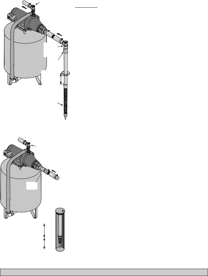
Figure 1: Driven Point Installation
To Household
 Water System
Pump Priming |
Tee with Plug |
or Gauge |
Suction Pipe
From Well
Check Priming
Valve |
Tee and |
Plug
Sanitary
Well Seal
1862 0795
10' Foot
Min. Valve
5–10'
Figure 2: Cased Well Installation
Replacing An Old Pump


 Hazardous voltage.. Disconnect power to pump before working on pump or motor.
1.Drain and remove the old pump. Check the old pipe for scale, lime, rust, etc., and replace it if necessary.
2.Install the pump in the system. Make sure that all pipe joints in the suction pipe are air-tight as well as water tight. If the suction pipe can suck air, the pump will not be able to pull water from the well.
3.Adjust the pump mounting height so that the plumbing connections do not put a strain on the pump body. Support the pipe so that the pump body does not take the weight of piping or fittings.
You have just completed the well plumbing for your new shallow well jet pump. Please go to Page 6 for discharge pipe and tank connections.
Well Point (Driven Point) Installation (Figure 1)
1.Drive the well, using “drive couplings” and a “drive cap”. “Drive fittings” are threaded all the way through and allow the pipe ends to butt against each other so that the driving force of the maul is carried by the pipe and not by the threads. The ordinary fittings found in hardware stores are not threaded all the way through the fitting and can collapse under impact. “Drive fittings” are also smoother than standard plumbing fittings, making ground penetration easier.
2.Mount the pump as close to the well as possible.
3.Use the fewest possible fittings (especially elbows) when connecting the pipe from the well point to the pump suction port. The suction pipe should be at least as large as the suction port on the pump (include
a check valve if your pump is not equipped with one – see Figure 1). Support the pipe so that there are no dips or sags in the pipe, so it doesn’t strain the pump body, and so that it slopes slightly upward
from the well to the pump (high spots can cause air pockets which can air lock the pump). Seal the suction pipe joints with 1Teflon™ tape or a Teflon™ based pipe joint compound. Joints must be airand watertight. If the suction pipe can suck air, the pump cannot pull water from the well. If one well point does not supply enough water, consider connecting two or three well points to one suction pipe.
You have just completed the suction piping for your new shallow well jet pump. Please go to Page 6 for discharge pipe and tank connections.
1 E. I. DuPont de Demours and Company Corporation, Delaware
Cased Well Installation, 2” or Larger Casing (Figure 2)
1.Mount the pump as close to the well as possible.
2.Assemble the foot valve, strainer, and well pipe (see Figure 2). Make sure that the foot valve works freely.
3.Lower the pipe into the well until the strainer is five feet above the bottom of the well. It should also be at least 10 feet below the well’s water level while the pump is running in order to prevent the pump from sucking air. Install a sanitary well seal.
For parts or assistance, call Sta-Rite® Customer Service at 1-888-782-7483

Installation |
5 |
|
|
To Household |
Pump Priming |
Water System |
Tee with Plug |
|
or Gauge |
Suction Pipe
From Water
Source
Priming
Tee and
Plug
1863 0205
10' |
Foot |
Min. |
Valve |
5–10' |
|
|
Screen |
Figure 3: Surface Water Installation
4.Install a priming tee, priming plug, and suction pipe to the pump (see Figure 2). Connect the pipe from the well to the pump suction port, using the fewest possible fittings – especially elbows – as fittings increase friction in the pipe (however, include a foot valve – see Figure 2). The suction pipe should be at least as large as the suction port on the pump. Support the pipe so that there are no dips or sags in the pipe, so it doesn’t strain the pump body, and so that it slopes slightly upward from the well to the pump (high spots can cause air
pockets which can air lock the pump). Seal the suction pipe joints with Teflon™ tape or a Teflon™ based pipe joint compound. Joints must be airand water-tight. If the suction pipe can suck air, the pump cannot pull water from the well.
You have just completed the suction piping for your new shallow well jet pump. Please go to Page 6 for discharge pipe and tank connections.
Installation for Surface Water (Figure 3)


 Possible contamination.. Do not use surface water for drinking. The installation shown could be used for sprinkler applications.
1.The pump should be installed as close to the water as possible, with the fewest possible fittings (especially elbows) in the suction pipe. The suction pipe should be at least as large as the suction port on the pump.
2.Assemble a foot valve and suction pipe (see Figure 3). Make sure that the foot valve works freely. Use Teflon™ tape or a Teflon™-based pipe joint compound on threaded pipe joints. Protect the foot valve assembly from fish, trash, etc, by installing a screen around it (see Figure 3).
3.Lower the pipe into the water until the strainer is five feet above the bottom. It should also be at least 10 feet below the water level in order to prevent the pump from sucking air.
4.Install a priming tee, priming plug, and suction pipe to the pump (see Figure 3). Support the pipe so that there are no dips or sags in the pipe, so it doesn’t strain the pump body, and so that it slopes slightly upward from the well to the pump (high spots can cause air pockets which can air lock the pump). Seal the suction pipe joints with Teflon™ tape or
a Teflon™ based pipe joint compound. Joints must be airand watertight. If the suction pipe can suck air, the pump cannot pull water from the well.
You have just completed the plumbing for your new shallow well jet pump. Please go to Page 6 for discharge pipe and tank connections.
For parts or assistance, call Sta-Rite® Customer Service at 1-888-782-7483
Discharge Pipe and Pressure Tank Connections |
6 |
|
|
|
To Household |
|
|
Water System |
|
|
Pump Priming |
|
|
Tee with Plug |
|
|
or Gauge |
|
Pressure |
From Well |
|
Switch |
||
|
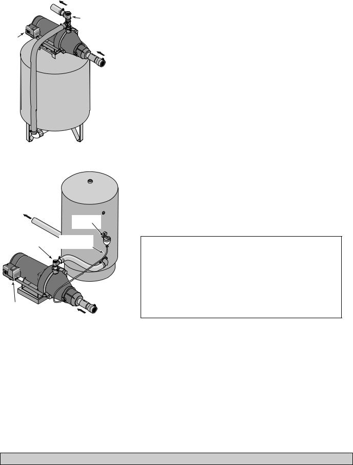
Figure 4: Pre-charged Tank Connections
To Household
Water System
|
Air Volume |
|
|
Control |
|
Pump Priming Tee |
Air Volume |
|
with Plug or Gauge |
||
Control Tube |
||
|
Pressure
Switch From
Well
Figure 5: Standard Tank Connections
Pre-Charge Tank Connection (Figure 4)
1.Install two tees in the pump discharge port (see Figure 4). The pipe size must be at least as large as the discharge port.
2.Run a pipe or reinforced hose from one arm of the first tee to the port on the pre-charged tank.
3.Connect the other end of the discharge tee to your plumbing system. Cap the tee with a threaded plug or a pressure gauge.
4.Check the pre-charge of air in the tank with an ordinary tire gauge. The pre-charge should be 2 PSI less than the cut-in setting of the pump’s pressure switch. The pre-charge is measured when there is no water pressure in the tank. Your new pump has a 30/50 PSI switch, so adjust the tank pre-charge pressure to 28 PSI.*
Congratulations! You have just completed the tank connection for your jet pump. Please go to Page 7 for electrical hookup.
* Model PNCSS does not include a pressure switch.
Standard Tank Connection (Figure 5)
1.Install one tee in the pump discharge port (see Figure 5).
2.Run a pipe from the pump discharge port to the inlet port of your tank. The pipe size must be at least as large as the discharge port.
3.Install a tee in the suction pipe near the pump. Install a reducer bushing down to 1/8” NPT in the tee. Run tubing from the tee to the port on the AVC mounted on the tank. Seal all joints with Teflon™ tape. See instructions provided with the tank and the AVC for details.
Congratulations! You have just completed the tank connection for your jet pump. Please go to Page 7 for electrical hookup.
Sealing Pipe Joints
Use only 1Teflon™ tape or Teflon™ based joint compounds for making all threaded connections to the pump itself. Do not use pipe joint compounds on plastic pumps: they can react with the plastic in pump components. Make sure that all pipe joints in the suction pipe are air tight as well as water tight. If the suction pipe can suck air, the pump will not be able to pull water from the well.
1 E. I. DuPont de Demours and Company Corporation, Delaware
For parts or assistance, call Sta-Rite® Customer Service at 1-888-782-7483

Electrical |
7 |
|
|
 Disconnect power before working on pump, motor, pressure switch, or wiring..
Motor Switch Settings
NOTICE: 1/2 HP and 1/3 HP motors are dual voltage and are factory set to 115 V. 3/4 HP motors are also dual voltage, but are factory set to 230 V. Motor terminal board (located under the motor end cover) should look like that shown below. Use the instructions to set your motor to match your power source.


 Never connect a motor set to 115 V to a 230 V power source.
Plug Type Voltage Selector
Voltage is set to 230 V.. To change to 115 V:
Power Connections
Voltage Change Plug
Ground Wire Connection |
Pressure Switch |
|
Figure 6:Voltage set to 230 V, Plug Type
1.Make sure power is off.
2.Pull the voltage change plug off of the tabs.
3.Move the voltage change plug to the 115 V position. The plug will now cover 2 metal tabs and the arrow on the plug will line up with the 115 V arrow on the label (see Figure 7).
Figure 7:Voltage set to 115 V, Plug Type
4.Attach the incoming power leads to the two outer screws on the pressure switch as shown in Figure 6.
5.Attach the ground wire to one of the grounding connections, shown in Figure 6.
6.If there are other wires, they should be capped.
7.Reinstall the motor end and pressure switch covers.
Dial Type Voltage Selector
Voltage is set to 230 V.. To change to 115 V:
Power Supply Connections
Voltage
Change
Dial
Pressure Switch
Ground Wire Connection
Figure 8:Voltage set to 230 V, Dial Type
1.Make sure power is off.
2.Turn the dial counter-clockwise until 115 shows in the dial window as shown in Figure 9.
Figure 9:Voltage set to 115 V, Dial Type
3.Attach the incoming power leads to the two outer screws on the pressure switch as shown in Figure 8.
4.Attach the ground wire to the grounding connections as shown in Figure 8.
5.If there are other wires, they should be capped.
6.Reinstall the motor end and pressure switch covers.
For parts or assistance, call Sta-Rite® Customer Service at 1-888-782-7483

Electrical |
8 |
|
|
 Hazardous voltage.. Can shock, burn, or kill. Connect ground wire before connecting power supply wires. Use the wire size (including the ground wire) specified in the wiring chart. If possible, connect the pump to a separate branch circuit with no other appliances on it.


 Explosion hazard.. Do not ground to a gas supply line.
Wiring Connections
 Fire hazard.. Incorrect voltage can cause a fire or seriously damage the motor and voids the warranty. The supply voltage must be within ±10% of the motor nameplate voltage.
NOTICE: Dual-voltage motors may be set for 115 V or 230 V. If necessary, reset the motor to the desired voltage, as shown. Do not alter the wiring in single voltage motors.
Install, ground, wire, and maintain your pump in compliance with the National Electrical Code (NEC) or the Canadian Electrical Code (CEC), as applicable, and with all local codes and ordinances that apply. Consult your local building inspector for code information.
Connection Procedure:
1.Connect the ground wire first as shown in Figure 6. The ground wire must be a solid copper wire at least as large as the power supply wires.
2.There must be a solid metal connection between the pressure switch and the motor for motor grounding protection. If the pressure switch is not connected to the motor, connect the green ground screw in the switch to the green ground screw under the motor end cover. Use a solid copper wire at least as large as the power supply wires.
3.Connect the ground wire to a grounded lead in a service panel, to a metal underground water pipe, to a metal well casing at least ten feet (3 m) long, or to a ground electrode provided by the power company or the hydro authority.
4.Connect the power supply wires to the pressure switch as shown in Figure 6.
You have just completed the wiring for your pump.
Please go to Page 9 for startup preparations.
Wiring Chart – Recommended Wire and Fuse Sizes
|
|
|
|
|
DISTANCE IN FEET FROM MOTOR TO SUPPLY |
|
|||
|
|
|
|
|
|
|
|
|
|
|
|
Max.. Load |
Branch Fuse |
0 - 50 |
51 - 100 |
101 - 200 |
201 - 300 |
301 - 400 |
401 - 500 |
|
|
|
|
|
|
|
|
||
Motor HP |
Volts |
Amp |
Rating Amp |
|
|
AWG WIRE SIZE (mm2) |
|
|
|
1/3 |
115/230 |
9.9/4.95 |
15/15 |
14 (2) |
14 (2) |
10 (5.5) |
10 (5.5) |
8 (7) |
6 (14) |
|
|
|
|
|
|
|
|
|
|
1/2 |
115/230 |
9.9/4.95 |
15/15 |
14 (2) |
14 (2) |
10 (5.5) |
10 (5.5) |
8 (7) |
6 (14) |
|
|
|
|
|
|
|
|
|
|
3/4 |
115/230 |
12.2/6.1 |
20/15 |
14/14 (2/2) |
14/14 (2/2) |
10/14 (5/2) |
8/14 (7/2) |
8/14 (7/2) |
6/12 (9/3) |
|
|
|
|
|
|
|
|
|
|
For parts or assistance, call Sta-Rite® Customer Service at 1-888-782-7483
 Loading...