


System 2TM
Modular Media Filters
O W N E R ’ S M A N U A L
RELEASE
RELEASE
OUTLET
OUTLET 
INSTALLATION, OPERATION & PARTS
|
|
MODELS |
|
|
PLM100 |
PLM125 |
PLM150 |
PLM175 |
PLM200 |
|
|
PLM300 |
|
|
This manual should be furnished to the end user of this filter; its use will reduce service calls and chance of injury and will lengthen filter life.
Pentair Water Pool and Spa, Inc.
© 2010 Pentair Water Pool and Spa, Inc. All rights reserved. This document is subject to change without notice. 1620 Hawkins Ave., Sanford, NC 27330 • (919) 566-8000
10951 West Los Angeles Ave., Moorpark, CA 93021 • (805) 553-5000
Customer Support: (800) 831-7133
System 2™, Posi-Lok™, Sta-Rite® and Pentair Water Pool and Spa® are trademarks and/or registered trademarks of Pentair Water Pool and Spa, Inc. and/or its affiliated companies in the United States and/or other countries. Unless noted, names and brands of others that may be used in this document are not used to indicate an affiliation or endorsement between the proprietors of these names and brands and Pentair Water Pool and Spa, Inc. Those names and brands may be the trademarks or registered trademarks of those parties or others. Printed in U.S.A.
03-17-10 |
S338 (Rev. A) |
E N G L I S H
F R A N
Ç
A
I
S
E S P A
Ñ
O
L
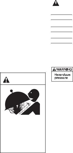
Table of Contents |
|
Safety Instructions........................................................................................... |
2 |
General Information......................................................................................... |
3 |
Specifications .................................................................................................. |
4 |
Installation ....................................................................................................... |
5 |
Initial Startup.................................................................................................... |
6 |
Filter Disassembly / Assembly...................................................................... |
6-7 |
Module Cleaning Procedure ......................................................................... |
7-8 |
Special Cleaning Instruction ......................................................................... |
8 |
System Inspection/Winterizing......................................................................... |
9 |
Troubleshooting Guide .................................................................................. |
10 |
Repair Parts List ............................................................................................ |
11 |
WARNING |
Hazardous Pressure! |
Can cause tank |
explosion. |
Do not connect filter to |
compressed air under any |
circumstances. |
READ AND FOLLOW SAFETY INSTRUCTIONS!
This is the safety alert symbol. When you see this symbol on your filter or in
 this manual, look for one of the following signal words and be alert to the potential for personal injury.

 warns about hazards that will cause death, serious personal injury, or major property damage if ignored.


 warns about hazards that can cause death, serious personal injury, or major property damage if ignored.


 warns about hazards that will or can cause minor personal injury or property damage if ignored.
NOTICE indicates special instructions not related to hazards.
Carefully read and follow all safety instructions in this manual and on equipment. Keep safety labels in good condition; replace if missing or damaged.
Incorrectly installed or tested equipment may fail, causing severe injury or property damage. Read and follow instructions in owner's manual when installing and operating equipment. Have a trained pool professional perform all pressure tests.
1.Do not connect system to a city water system or other external source of pressurized water.
2.Use equipment only in a pool or spa installation.
3.Trapped air in system can cause explosion. BE SURE all air is out of system before operating or testing equipment.
Before pressure testing, make the following safety checks:
•Check all clamps, bolts, lids, lock rings and system accessories before testing.
•Release all air in system before testing.
•Tighten Sta-Rite pump trap lids to 30 ft. lbs. (4.1 kg-cm) torque for testing.
•Water pressure for test must be less than 25 PSI (172 kPa).
•Water Temperature for test must be less than 100o F. (38o C).
•Limit test to 24 hours. After test, visually check system to be sure it is ready for operation. Remove pump trap lid and retighten hand tight only.
NOTICE: These parameters apply to Sta-Rite equipment only. For non-Sta-Rite equipment, consult equipment manufacturer.
2
When to Clean the Filter
The filter module should normally be cleaned when the pressure gauge reading increases 10 PSI over the start-up pressure (record the start-up pressure under “Owner’s Information”, below, right).
In some pools, accessories such as fountains or pool cleaners may be noticeably affected by the normal decrease in flow as the filter becomes dirty. If so, clean the filter more frequently (that is, at a pressure increase of less than 10 PSI) in order to maintain the required flow.
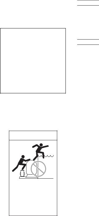
 WARNING
Risk of drowning and falls. Place equipment at least 4 feet from pool so that children cannot
climb over it into pool.
sss
Do not allow children to stand or play on filter or pump.
GENERAL INFORMATION
•Clean a new pool as well as possible before filling pool and operating filter. Excess dirt and large particles of foreign matter in the system can cause serious damage to the filter and pump.
•With a permanent media filter in place and operating correctly, clean water is returned to the pool faster than pool water is being contaminated. A typical pool installation will require approximately one week to obtain and maintain the sparkle that your filter is capable of giving you.
•Maximum pressure is 50 PSI (345 kPa). DO NOT connect the filter to a city water system or to an individual water well system.


 Hazardous pressure. Open air release valve to vent all air from system before operating system. NEVER operate filter with air trapped inside.
•The Sta-Rite modular media filter is designed to filter water for swimming pools and spas. On a new installation, we recommend:
1. Disassemble the filter after the initial cleanup.


 Hazardous pressure. To prevent severe injury or major property damage, exactly follow "Filter Disassembly/Assembly Procedure" on Pages 6 and 7.
2. Remove and hose down the element assembly to remove contaminants.
•Maintain pool water pH between 7.2 and 7.6.
•Make sure that internal air bleed tube and filter are clean and installed properly at top of module before operating filter.
•Make sure that Posi-Lok™ Ring is securely locked in place before operating filter.
•Maintain pressure gauge in good working order. Replace a damaged gauge immediately.
•Cleaning interval is based on pressure rise, not on length of time filter is operated. Different water conditions will have different normal cleaning intervals.
•Check local codes for restrictions on waste water disposal requirements.
NOTICE: Some pool disinfectants may clog filter module. To maximize module life and filter cycle time, closely follow disinfectant manufacturer’s instructions when cleaning pool or filter. Failure to follow these instructions may affect warranty coverage of the module.
Owner’s Information
Serial Number ______________________________________________
Dealer ____________________________________________________
Dealer’s Telephone # _________________________________________
Purchase Date ______________________________________________
Pressure Gauge Reading at Startup _____________________________
Installation Date _____________________________________________
3

SPECIFICATIONS
Dim B
Minimum
Service
Height
Air Release Valve
(Pressure Gauge
Behind)
Upper
Tank
Shell
Posi-Lok™
Ring 
Dim A
Safety |
|
|
|
Latch |
|
|
|
Lower |
|
18.58" Dia. |
|
Tank |
|
||
|
(472 mm) |
||
Shell |
|
||
Outlet |
Inlet |
||
2" NPT |
|||
2" NPT |
or Drain |
||
Inlet or |
|||
|
2" NPT |
||
Drain |
|
||
|
|
||
Drain |
|
|
|
Plug |
|
|
4310 0203
15" Dia. |
|
|
|
2.25" |
|||
(381 mm) |
|||
|
(57 mm) |
||
|
|
||
FIGURE 1A – Dimensions in inches (mm)
Filter |
Inlet |
|
|
Outlet |
|
IINLET |
Pump |
To Pool |
|
From
Pool |
4085 1001 |
FIGURE 1B – Piping Connections
20 (138)
(kPa) |
18 |
(124) |
|
||
Inch |
16 |
(110) |
14 (97) |
||
inDropPressure SquareperPounds |
12 (88) |
|
|
||
10 (69)
8 (55)
6 (41)
4 (28)
2 (14)
10 |
20 |
40 |
60 |
80 |
100 |
120 |
140 |
160 |
(38) |
(76) |
(151) |
(227) |
(303) |
(378) |
(454) |
(529) |
(606) |
|
Flow in Gallons Per Minute (LPM) |
|
150 |
|||||
|
|
|
|
|
|
|
(568) |
|
FIGURE 2 – Pressure Drop Curve
Table 1 - Filter Specifications
|
|
|
Model No. |
|
|
|
|
PLM100 |
PLM125 |
PLM150 |
PLM175 |
PLM200 |
PLM300 |
Filter Area sq. ft. (m2) |
100(9.3) |
125(11.6) |
150(14) |
175(16.3) |
200(18.6) |
300(27.9) |
Max. Rated Flow GPM (LPM) |
|
|
|
|
|
|
Commercial |
37(140) |
47(178) |
56(212) |
66(249) |
75(284) |
113(428) |
Max. Operating Pressure PSI (kPa) |
50(345) |
50(345) |
50(345) |
50(345) |
50(345) |
50(345) |
Max. Continuous Water |
|
|
|
|
|
|
Temperature F(C) |
104°(40°) |
104°(40°) |
104°(40°) |
104°(40°) |
104°(40°) |
104°(40°) |
Dimension A – Height (mm) |
27-3/4(705) |
27-3/4(705) |
27-3/4(705) |
27-3/4(705) |
27-3/4(705) |
37-5/8(956) |
Dimension B – Minimum Service |
|
|
|
|
|
|
Height (mm) |
38-1/2(978) |
38-1/2(978) |
38-1/2(978) |
38-1/2(978) |
38-1/2(978) |
57(1,448) |
|
|
|
|
|
|
|
4
NOTICE
Make sure that the filter and all piping can be drained for winterizing. See “Winterizing”, Page 9.
INSTALLATION
Installation of filter should only be done by qualified, licensed personnel.
Filter mount must:
•Provide weather and freezing protection.
•Provide space and lighting for easy access for routine maintenance. (See Figure 1 for space requirements.)
•Provide ventilation and drainage for pump.
•Be on a reasonably level surface and provide adequate drainage.
Piping (See Figure 1B for correct connections):
•Piping must conform to local/state plumbing and sanitary codes.
•Use teflon tape, Plasto-Joint Stik®1 (provided), or Silastic 732® on all male connections of plastic pipe and fittings. DO NOT use pipe compounds on plastic pipe; it will cause the pipe to crack. Do not use sealant on unions – assemble them dry and hand tight.
•Support pipe independently to prevent strains on filter.
•Fittings restrict flow; for best efficiency use fewest possible fittings. NOTICE: Run outlet (return) piping to the filter port marked ‘outlet’ (see Figure 1A). Run inlet and drain piping to the other two 2” NPT ports which are not marked. These two ports (inlet and drain) are interchangeable to allow for the most convenient piping run. After you have piped the inlet and drain, apply the ‘inlet’ decal to the port to which you have run the inlet piping.
•For ease of maintenance, use Sta-Rite union couplings to connect the piping to the filter inlet and outlet ports.
•Keep piping tight and free of leaks: pump suction line leaks may cause trapped air in filter tank or loss of prime at pump; pump discharge line leaks may show up as dampness or jets of water.
•NOTICE: Overtightening can crack filter ports.
Valves:
•Install valves on both sides of the filter to isolate filter for easy servicing.
NOTICE: Install heater downstream of filter. If heater does not incorporate a check valve, install one at the heater inlet to prevent hot water from backing up into the filter. Filter modules damaged by excessive heat will void the warranty.
•A check valve installed ahead of filter inlet will prevent contaminants from draining back into pool.
Electrical:
•BE SURE filter grounding and bonding meets local and National Electrical Code standards. All wiring, grounding and bonding of associated equipment must meet local and National Electrical Code Standards.
Plasto-Joint Stik® is a registered trademark of La-Co Industries, Inc. and Silastic 732® is a registered trademark of Dow Corning Corp.
5
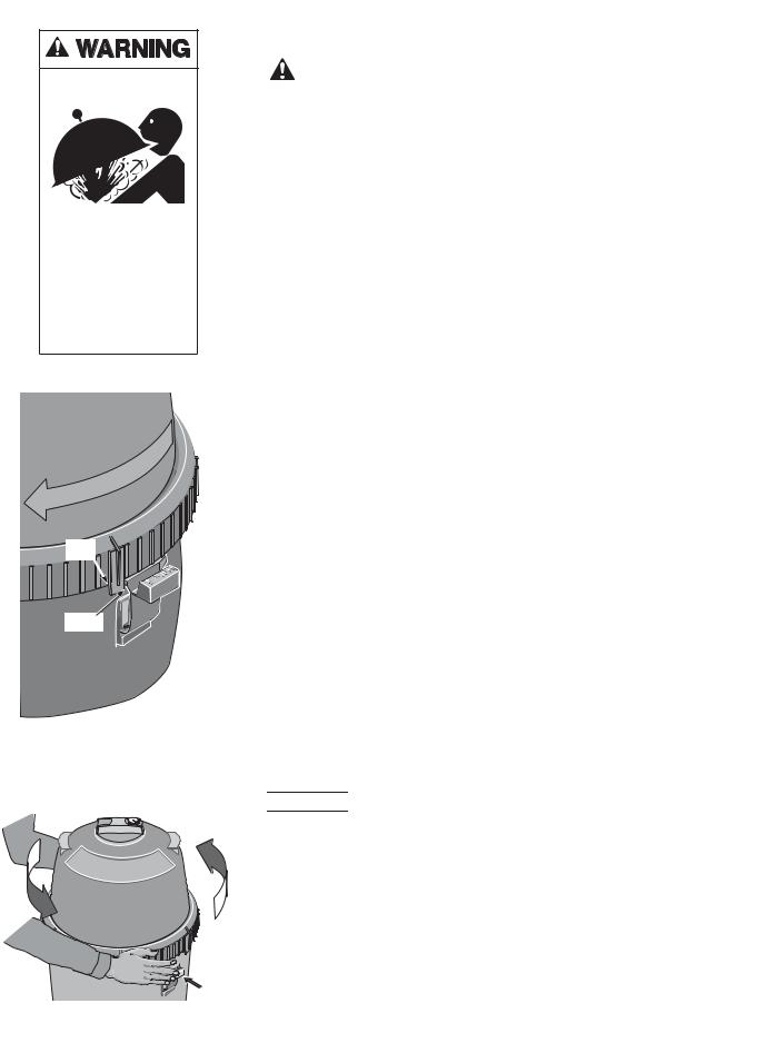
Hazardous pressure. Can cause severe injury or major property damage from tank blow up.
Release all pressure and read instructions before working on filter.
Tab
Latch
1195
Figure 3 – Rotate Posi-Lok™ Ring until tab locks behind the safety latch.
Figure 4 –DepressDepressSafetysafetyLatchlatch to unscrewto Posiunscrew-Lok™PosiRing-Lok™.
INITIAL START-UP
 Be sure pump is OFF before starting procedure.
Do not operate these filters at more than 50 PSI (345 kPa) under any
 circumstances!
1. Securely lock Posi-Lok™ ring in place by rotating ring CLOCKWISE until  it “clicks” past the safety latch (see Figure 3). Stop turning as soon as the ring clicks past the latch. The ring may feel slightly loose, but it will tighten up when pump is on and filter is under pressure.
2.Fill trap on pump with water.
3.Open air release valve on top of filter.
4.Open isolation valves.
5.Start pump to purge air from system.
6.When steady stream of water comes from air release valve, close the valve.
NOTICE: Leaking around the Posi-Lok™ ring may indicate that the ring is not fully locked. In this case, proceed as follows:
A.Stop the pump, close the isolation valves, and open the air release valve to release any pressure within the filter.
B.Remove the drain plug and drain all water from the filter.
C.Push down on the top of the filter to fully seat the upper tank shell.
D.Rotate the Posi-Lok™ clockwise until it locks behind the safety latch (see Figure 3).
E.If the ring was already locked, remove it and the upper tank shell.
Inspect and clean the O-ring and all sealing surfaces. Relubricate the
O-ring.
NOTICE: Lubricate O-ring only with the silicone grease provided or equivalent, as other lubricants may cause the ring to swell. DO NOT lubricate Posi-Lok™ ring or threads on lower tank shell as this may collect grit and make removal difficult.
After filter is operating, record filter pressure gauge reading in owner's manual for future use.
NOTICE: When installed on a new pool, after approximately 48 hours of operation disassemble filter and clean out plaster dust , construction debris, etc. (see “Module Cleaning Procedure", Pages 7 and 8).
FILTER DISASSEMBLY/ ASSEMBLY PROCEDURE
 Hazardous pressure. Before disassembling filter:
1.STOP PUMP.
2.CLOSE isolation valves.
3.OPEN air release valve and drain fitting.
4.WAIT until all pressure is released and water drained from filter tank and system before loosening Posi-Lok™ Ring.
Disassembly:
1.Stop the pump.
2.Close isolation valves to prevent flooding.
3.Open air release valve on top of filter tank to release all pressure from inside of tank.
6

Figure 5 – Insert ring tab in slot in
2152 1195
filter body.
Figure 6 – Roll ring to one side to loosen upper tank half.
Small
Catch
Figure 7 – Safety Latch
When to Clean the Filter
The filter module should normally be cleaned when the pressure gauge reading increases 10 PSI over the start-up pressure (record the start-up pressure under “Owner’s Information”, Page 3).
In some pools, accessories such as fountains or pool cleaners may be noticeably affected by the normal decrease in flow as the filter becomes dirty. If so, clean the filter more frequently (that is, at a pressure increase of less than 10 PSI) in order to maintain the required flow.
NOTICE: Make sure that waste water disposal complies with local codes and ordinances.
4.Remove drain plug and drain all water from tank.
5.Remove Posi-Lok™ ring as follows:
a.Press safety latch (below the ring) toward the tank to release it (see Figure 4).
b.Hold latch in the release position and rotate ring COUNTERCLOCKWISE to remove. If ring is difficult to turn, tap gently with a rubber mallet to overcome initial resistance.
NOTICE: DO NOT use screwdriver or bladed instrument that may damage shell surfaces to pry tank shells apart.
6.Separate upper and lower tank shell halves using tabs on bottom of PosiLok™ ring. Insert tab into slot located at tank joint and twist ring to pry shell halves apart. See Figures 5 and 6.
7.Remove O-ring from upper tank shell. Inspect for cuts, cracking, deformation or signs of wear; replace if necessary.
NOTICE: To avoid strain or damage, allow filter module to drain before lifting it out of the tank.
SAFETY LATCH (See Figure 7)
The purpose of the safety latch is to hold the Posi-Lok™ ring in the locked position. If the latch is damaged, replace it as follows:
1.Press down on the small catch behind the safety latch and press or tap the latch out of the “Tee” slot in the tank (see Figure 7).
2.Snap the new latch into position.
NOTICE: DO NOT operate the filter if the safety latch is damaged or will not hold the Posi-Lok™ ring in the locked position.
Assembly:
1.Inspect and clean the tank, ring threads and O-ring groove. Replace damaged parts as necessary.
2.Install the filter by placing the port in the bottom of the filter cartridge over the tank outlet port. Push down firmly to seal.
3.Ensure that the air bleed assembly on top of the module is clean and properly mounted.
NOTICE: Lubricate O-ring only with the silicone grease provided or equivalent, as other lubricants may cause the ring to swell. DO NOT lubricate Posi-Lok™ ring or threads on lower tank shell as this may collect grit and make removal difficult.
4.Install the O-ring in the upper tank shell O-ring groove. Be sure that the O-ring is clean and not twisted.
5.Push the upper tank shell into the lower tank shell to compress the O-ring.
6.Place the Posi-Lok™ ring squarely over the tank shell threads and rotate COUNTERCLOCKWISE until the ring falls into the slots; then rotate CLOCKWISE until securely latched.
7.Follow instructions in the “Initial Startup” section of this manual.
MODULE CLEANING PROCEDURE
Follow all steps in the “Disassembly” section of this manual.
The filter module should be removed and cleaned when pressure rises more than 10 psi (69 kPa) above startup pressure. See also “When to Clean the Filter,” at left.
7

Recommended Specialty Filter
Cleaners
Filter Cleanse™, Strip-Kwik®,
KleenIt™, Softswim®**, Filter
Kleen™, Baqua Clean™
** MUST be used when using any PHMB based sanitizer.
Filter Cleanse™ is a trademark of Advantis Technologies, Inc., Strip-Kwik®, KleenIt™, and Softswim® are trademarks and/or registered trademarks of Bio-Lab, Inc., Filter Kleen™ is a trademark of Haviland Consumer Products, Inc. and Baqua Clean™ is a trademark of Zeneca Limited Corp.


 Risk of chemical burns. Do not attempt to acid clean the filter or module. If the filter requires acid cleaning, have a trained pool professional do the job.
NOTICE: When sanitizing your pool using PHMB (polyhexamethylene biquanide based) cleaners, use only PHMB cleaners to clean the module. When using PHMB sanitizers, the filter module MUST be cleaned more thoroughly and frequently than for a pool using chlorine. Follow manufacturer’s instructions carefully. Use of any other type of cleansers with PHMB pool sanitizers will void the filter’s warranty.
NOTICE: Avoid washing filter debris into the outlet port. Remove drain plug and flush foreign material from inside of tank before removing filter module.
1.With a hose equipped with a soft flow nozzle, wash as much dirt as possible off of the filter module while it is still inside the tank. Allow tank to drain completely.
2.Make sure that the inside of the tank is clean. Lift out the module and hose it down thoroughly. Spray the entire module surface. Allow module to drain.
3.Inspect the module. If necessary, repeat the washing operation. If the module is damaged, replace it.
NOTICE: If this cleaning method does not remove all deposits, see “Special Cleaning Instructions” section in this manual.
4.Inspect and clean air bleed filter at top of module.
5.Follow all steps in the “Assembly” and “Initial Startup” sections of this manual.
Special Cleaning Instructions:
Use this procedure to clean scale or oils which are not removed by hosing down module. Be sure to dispose of spent chemicals according to all applicable codes and waste disposal ordinances. Use a soft stream nozzle to minimize flying water and spray.


 Risk of fire or explosion. Isolate filter from system before chemical cleaning; rinse filter and elements completely before returning to service. If filter cannot be isolated, remove media and clean at another location.
Follow chemical manufacturer’s instructions for use. Do not mix chemicals except as directed by manufacturer. Do not allow cleaning chemicals to mix with or to come in contact with chlorine, bromines, other chemicals, or chemical feed devices.
1.Sponge or spray the module according to chemical manufacturer’s directions.
2.If soaking is required, remove the module from the filter tank and submerge it in a separate tank. Follow cleaner manufacturer’s instructions carefully.
3.After completing chemical manufacturer’s instructions, drain and rinse the module completely. Dispose of cleaners in accordance with local codes and disposal ordinances.
4.Rinse the inside of the filter tank. Drain it completely.
5.Follow instructions in the “Assembly” and “Initial Startup” sections of this manual.
8

NOTICE
The filter outlet piping will not empty through the filter drain. Make sure that the outlet piping has a separate drain for winterizing.
SYSTEM INSPECTION
General:
Wash the outside of the filter with a mild detergent and water. Rinse off with a hose.
NOTICE: DO NOT use solvents to clean the filter; solvents may damage plastic components in the system.
NOTICE: Open the air bleed valve and bleed all air from the filter each time the pump is stopped and restarted.
Weekly Inspection:
1.Remove debris from the pool skimmer basket.
2.Stop the pump; open the air release valve to release all pressure.
3.Remove the trap cover and basket; remove debris.
4.Check the pump for leaks. If found, see the pump owner's manual.
5.Replace the trap basket and the cover. Tighten the cover securely hand tight. DO NOT use a lid wrench to tighten it.
6.Start the pump. When the filter air release valve runs a solid stream of water, close the valve.
7.When the system has returned to normal operation, check the filter pressure. If the filter pressure is 10 PSI (69kPa) or more higher than the initial startup pressure, the filter needs cleaning. See “Module Cleaning Procedure”, Pages 7 and 8.
WINTERIZING


 Explosion hazard. Purging the system with compressed air can cause components to explode, with risk of severe injury or death to anyone nearby. Use only a low pressure (below 5 PSI), high volume blower when air purging the pump, filter, or piping.
NOTICE: Protect the filter from freezing. Allowing the filter to freeze will damage it and will void the warranty.
1.Clean the filter according to instructions (Pages 7 and 8) before winterizing.
2.Stop the pump.
3.Open the air release valve; open all the system valves.
4.Remove the drain plugs from the trap, pump, and filter.
5.Drain the system piping.
A.Gravity drain system as far as possible.
B.Protect areas which retain water with non-toxic propylene glycol antifreeze (“RV antifreeze”).
6.Loosen the union nuts (if used) to drain all water from the filter interior.
Leave these nuts loose until the system is restarted.
7.Disassemble the filter (follow instructions under “Filter Disassembly”,
Pages 6 and 7). Remove the filter module and store it in a warm, dry area.
8.If the filter is equipped with an optional internal spring check valve (in the tank outlet), manually open the check valve to allow any water trapped in the tank to drain.
9.Cover the filter with plastic or tarpaulin to prevent water entrance and freezing.
9
TROUBLESHOOTING GUIDE
1. Short Cycle Time:
NOTICE: CycleTime will vary with each installation and between different areas of the country. The following causes and remedies are for cycle times shorter than normal for your area.
A.Chlorine residual too low; maintain proper residual (consult pool professional for recommendation).
B.Flow rate too high; restrict flow to rated capacity of filter (see instruction plate on filter or specifications on Page 4).
C.Filter is too small; install an additional filter.
D.Filter module is dirty or plugged; thoroughly clean the filter (see No. 4, “Plugged Module Cloth”, and “Module Cleaning Procedure", Pages 7 and 8).
E.Water is chemically out of balance; consult pool professional.
F.Algae in the pool. Apply heavy dose of chlorine or algicide as recommended by the pool manufacturer.
2.Low Flow/High Pressure:
A.Elements plugged; clean filter thoroughly (see Pages 7 and 8).
B.Pipe blocked downstream from filter; remove obstruction.
C.Piping too small; use larger pipe (consult dealer for sizing).
D.Filter area too small; install an auxiliary filter (consult dealer for recommendation).
E.Outlet port check valve obstructed (if applicable); remove obstruction to allow valve to open.
3.Low Flow/Low Pressure:
A.Pump too small; consult dealer for recommendations.
B.Plugged pump or plugged hair and lint trap; clean thoroughly.
4.Plugged Module Cloth:
A.Insufficient cleaning; follow cleaning instructions closely and clean thoroughly (see Pages 7 and 8).
B.Water is chemically out of balance; consult pool professional.
C.Excessive air in filter. Vent air from tank and check for pump suction pipe leaks. Clean air bleed filter in module assembly with a hose and soft flow nozzle.
D.Filter is too small. Install an additional filter.
E.Pool water contains iron. See “Special Cleaning Instructions”, Page 8.
F.Heavy or improper application of powdered chlorine tablets using a binder. See “Special Cleaning Instructions”, Page 8.
G.Algae in the pool. Apply heavy dose of chlorine or algicide as recommended by the pool manufacturer.
H.Use of incorrect chemicals with PHMB sanitizers. Replace filter module.
5.Pool Water Not Clean:
A.Chlorine residual too low; maintain adequate chlorine residual (consult pool service technician for recommendation).
B.Filter module cloth torn, plugged, or punctured; replace module.
C.Inadequate turnover rate; consult dealer to verify that equipment is properly sized for your pool.
D.Pump is too large and is overpumping. Reduce the flow rate.
E.The filter is installed backwards. Reinstall it correctly.
F.Pool water contains iron. See “Special Cleaning Instructions”, Page 8.
G.Heavy or improper application of powdered chlorine tablets using a binder. See “Special Cleaning Instructions”, Page 8.
H.Algae in the pool. Apply heavy dose of chlorine or algicide as recommended by the pool manufacturer.
6.Pool Accessories Stop Working:
A.Clean filter and observe performance of accessories.
B.If accessories perform better after filter has been cleaned, use a shorter cleaning cycle for the filter (that is, clean the filter after a pressure rise of less than 10 PSI).
10
1 

2A
3A
4
5
RELEASE
6
7 


8

 11
11
2B
3B |
10 |
|
 12
12

 10
10

 13
13
OUTLET
9
Base rotated 90 to show check valve installed.
4309 0203
REPAIR PARTS
Key |
|
|
Part |
No. |
Description |
Qty. |
Number |
|
|
|
|
1 |
Posi-Lok™ ring* |
1 |
27001-0054 |
2A |
Air release valve assembly |
1 |
25010-0200 |
2B |
Air release valve |
|
|
|
assembly (PLM300) |
1 |
24206-0103S |
3A |
Tank shell upper half* |
1 |
27001-0020S |
3B |
Tank shell upper |
|
|
|
half (PLM300)* |
1 |
27001-0030S |
4 |
Tank O-ring |
1 |
27001-0061S |
5 |
Tank shell lower half |
1 |
27001-0009S |
6 |
Safety latch for ring |
1 |
27001-0051 |
7 |
1-1/2” NPT plug w/O-ring*** |
1 |
27001-0022S |
8 |
Adapter fitting*** |
1 |
24900-0510 |
9 |
2” x 1-1/2” Pipe reducer** |
2 |
U78-820P |
10 |
Pressure gauge*** |
1 |
15060-0000T |
11 |
Air bleed assembly |
1 |
24800-0121 |
12 |
Filter module (PLM100) |
1 |
27002-0100S |
12 |
Filter module (PLM125) |
1 |
27002-0125S |
12 |
Filter module (PLM150) |
1 |
27002-0150S |
12 |
Filter module (PLM175) |
1 |
27002-0175S |
12 |
Filter module (PLM200) |
1 |
27002-0200S |
12 |
Filter module (PLM300) |
1 |
27002-0300S |
13 |
Spring check valve** |
1 |
27001-0130S |
• |
Accessory package |
1 |
27001-0140 |
• |
Decal, logo |
1 |
27001-0041 |
• |
Decal, warning |
1 |
27001-0042 |
• |
Decal, operating instr. |
1 |
27002-0043 |
• |
Decal, nameplate (PLM100) |
1 |
27002-0042 |
• |
Decal, nameplate (PLM125) |
1 |
27002-0048 |
• |
Decal, nameplate (PLM150) |
1 |
27002-0045 |
• |
Decal, nameplate (PLM175) |
1 |
27002-0049 |
• |
Decal, nameplate (PLM200) |
1 |
27002-0050 |
• |
Decal, nameplate (PLM300) |
1 |
32155-4164 |
• |
Decal, inlet*** |
1 |
32165-4010 |
• |
Owner’s manual |
1 |
S338 |
• |
Teflon tape*** |
1 |
U97-58 |
• |
O-ring grease*** |
1 |
34725-0013 |
|
|
|
|
•Not illustrated.
* Includes all decals and labels.
**Optional equipment.
***Shipped in accessory package.
11
 Loading...