


OWNER’S MANUAL
INSTALLATION AND OPERATING INSTRUCTIONS
REPAIR PARTS LIST
60 CYCLE “J” and “JB” SERIES
CENTRIFUGAL PUMP
S
|
IT |
|
R |
E |
|
- |
|
|
A |
|
|
T |
|
|
 671 0294
MODELS
HP |
|
MEDIUM HEAD MODELS |
|
|
HIGH HEAD MODELS |
|
||||
1/3 |
JBMB-56S |
|
– |
JMB-56L |
|
– |
JBHB-61S |
– |
JHB-61HL |
– |
1/2 |
JBMC-56S |
|
JBMC3-56S |
JMC-56L |
|
JMC3-56 |
JBHC-61S |
JBHC3-61S |
JHC-61HL |
JHC3-61H |
3/4 |
JBMD-57S |
|
JBMD3-57S |
JMD-57L |
|
JMD3-57 |
JBHD-62S |
JBHD3-62S |
JHD-62HL |
JHD3-62H |
1 |
JBME-58S |
|
JBME3-58S |
JME-58L |
|
JME3-58 |
JBHE-63S |
JBHE3-63S |
JHE-63HL |
JHE3-63H |
1-1/2 |
JBMF-40S |
|
JBMF3-40S |
JMF-40L |
|
JMF3-40 |
JBHF-51S |
JBHF3-51S |
JHF-51HL |
JHF3-51H |
2 |
JBMG-41S |
|
JBMG3-41S |
JMG-41L |
|
JMG3-41 |
JBHG-52S |
JBHG3-52S |
JHG-52HL |
JHG3-52H |
2-1/2 |
JBMMG-59S |
|
JBMMG3-59S |
– |
|
– |
JBHHG-53S |
JBHHG3-53S |
JHHG-53HL |
JHHG3-53H |
293 WRIGHT STREET, DELAVAN, WISCONSIN 53115
©2005 |
S873 (Rev. 4/28/09) |

Tee and
Priming Plug
|
|
|
S |
Priming |
|
|
|
Plug |
|
|
|
Street Elbow |
Discharge |
|
|
to service |
|
|
|
|
Union |
|
|
|
|
|
|
|
|
Gate |
|
|
|
Valve |
Solid, level |
Vent |
Support discharge |
base |
|
|
|||
Plug |
pipe as required |
|
|
|
S |
|
|
|
T |
|
|
|
A |
|
|
|
- |
|
|
R |
R |
|
|
|
|
|
|
o |
|
|
|
t |
|
|
|
a |
|
|
|
t |
|
|
|
i |
|
|
|
o |
|
|
|
n |
|
|
|
|
Short length of |
|
|
straight pipe |
|
|
after reducer |
|
IT |
|
|
-R |
E |
|
A |
|
|
T |
|
|
|
|
Important: |
|
|
All connections must |
|
|
be air tight |
Eccentric |
Support suction pipe |
|
Reducer |
as required |
|
Straight run, short as 
 possible but at least 6 times pipe diameter ("D") sloping away from pump
Pipe diameter  "D"
"D"
As close as possible
Rotated Volute
Recommended pump suction |
4 x "D" |
and discharge connections |
minimum |
|
Foot |
Figure 1 |
Valve |
|
On the discharge avoid:

 Quick closing valves. Small I.D. pipe. Numerous fittings. Misalignment.
Sharp turns in piping run.
S
Concentric Reducer causes high spots along the suction line resulting in air pockets.
-RITE
TA
Concentric
Reducer
Long suction run
|
|
|
|
IT |
|
|
|
|
R |
E |
|
|
|
- |
|
|
|
S |
T |
A |
|
|
|
|
|
|
|
||
|
|
|
|
|
|
Elbow immediately in front of pump suction.
Use of excess fittings means potential air leaks
Valve
Unsupported
Pipe
High
lift
Pipe diameter "D"  insufficient size
Not recommended pump suction 
 and discharge connections Pipe submerged
less than 4 x "D" will cause vortexing
Figure 2 |
684 0294 |
2

PIPING - GENERAL
Support both suction and discharge piping independently at a point near the pump to avoid putting a strain on the pump housing. Start all piping AT THE PUMP.
Increase pipe diameter at both the suction and discharge by one (1) standard pipe size (minimum) to obtain desired performance and flow rate. Refer to Table I when sizing pipe for your pumping system.
NOTE: Do not use pipe with smaller diameter on the suction side of pump.
TABLE I
Pipe Tapping |
Recommended |
||
Size On Pump |
Pipe Size |
||
Suction |
Discharge |
Suction |
Discharge |
|
|
|
|
1-1/4 |
1 |
1-1/2 |
1-1/4 |
1-1/2 |
1-1/4 |
2 |
1-1/2 |
2 |
1-1/2 |
3 |
2 |
|
|
|
|
SUCTION PIPE
Increase pipe size from pump tapping as shown in Table I.
Figure 1 (Page 2) depicts a recommended run of pipe and fittings for the suction side of a centrifugal pump. Please refer to this illustration when choosing pipe and fittings for your suction connection.
IMPORTANT: All connections must be air tight!
Figure 2 (Page 2) depicts conditions that are NOT DESIRABLE on the suction side of a centrifugal pump and may cause problems in flow rate and priming. Please look this illustration over carefully before choosing pipe and fittings for your suction connection.
DISCHARGE PIPING
Increase pipe size from pump tapping as show in Table I.
Figure 1 (Page 2) depicts a recommended run of pipe and fittings for the discharge. Install tee with priming plug as close to pump as possible. Figure 2 (Page 2) notes conditions that should be avoided. Please read over carefully before making discharge connection.
PRIMING THE PUMP
A pump is primed when all air in the suction line and pump volute has been evacuated and replaced with water.
To Prime:
1.Close valve in discharge line.
2.Remove priming plug from tee and fill pump and suction line with water until water is flowing back out of tee.
3.Replace priming plug.
4.Start pump and slowly open valve until desired water flow is achieved.
NOTE: If water is not being pumped, turn off pump, close valve, and repeat steps 1 thru 4.
If pump volute is rotated as shown in Figure 1 (Page 2), loosen vent plug when priming to evacuate air trapped inside volute and tighten when volute is completely filled with water.


 Risk of explosion and scalding. Never run pump against closed discharge. To do so can boil water inside pump, causing hazardous pressure buildup and possible explosion.


 Risk of flooding. Do not run the pump dry. This will damage mechanical seal and void warranty. It may cause burns to person handling pump.


 Motor normally operates at high temperature and will be too hot to touch. It is protected from heat damage during operation by an automatic internal cutoff switch. Before handling pump or motor, stop motor and allow it to cool for 20 minutes.
TABLE II - RECOMMENDED FUSING AND WIRING DATA - 60 CYCLE MOTORS
|
|
BRANCH |
|
DIAMETER IN FEET FROM MOTOR TO METER |
|
|||
|
|
0’ |
51’ |
101’ |
201’ |
301’ |
401’ |
|
MOTOR |
MAX. LOAD |
FUSE* |
TO |
TO |
TO |
TO |
TO |
TO |
HP |
AMPERES |
RATING |
50’ |
100’ |
200’ |
300’ |
400’ |
500’ |
|
|
AMPS |
|
|
WIRE SIZE |
|
|
|
|
|
|
SINGLE PHASE - 115/230 VOLT |
|
|
|
||
1/3 |
9.4/4.7 |
15/15 |
14/14 |
14/14 |
10/14 |
10/14 |
6/14 |
6/12 |
1/2 |
9.4/4.7 |
15/15 |
14/14 |
14/14 |
10/14 |
10/14 |
6/14 |
6/12 |
3/4 |
12.2/6.1 |
20/15 |
12/14 |
12/14 |
10/14 |
8/14 |
6/12 |
6/12 |
1 |
14.8/7.4 |
20/15 |
12/14 |
12/14 |
8/14 |
6/14 |
6/12 |
4/10 |
1-1/2 |
19.2/9.6 |
25/15 |
10/14 |
10/14 |
8/14 |
6/12 |
4/10 |
4/10 |
2 |
24.0/12.0 |
30/15 |
12/14 |
10/14 |
6/14 |
6/12 |
4/10 |
4/10 |
|
|
|
THREE PHASE - 230/460 VOLT |
|
|
|
||
1/2 |
2.3/1.15 |
15/15 |
14/14 |
14/14 |
14/14 |
14/14 |
14/14 |
14/14 |
3/4 |
3.1/1.55 |
15/15 |
14/14 |
14/14 |
14/14 |
14/14 |
14/14 |
14/14 |
1 |
3.6/1.8 |
15/15 |
14/14 |
14/14 |
14/14 |
14/14 |
14/14 |
14/14 |
1-1/2 |
4.7/2.35 |
15/15 |
14/14 |
14/14 |
14/14 |
14/14 |
14/14 |
14/14 |
2 |
6.8/3.4 |
15/15 |
14/14 |
14/14 |
14/14 |
14/14 |
12/14 |
12/14 |
2-1/2 |
8.5/4.25 |
15/15 |
14/14 |
14/14 |
14/14 |
14/14 |
12/14 |
10/14 |
*A Fusetron is recommended instead of a fuse in any motor circuit.
3

ELECTRICAL
Connection diagram for dual voltage, single-phase motors. Your dual-voltage motor’s terminal board (under the motor end cover) will match one of the diagrams below. Follow that diagram if necessary to convert motor to 115 Volt power.
Connect power supply wires to L1 and L2. For 3-phase motors, or if motor does not match these pictures, follow the connection diagram on the motor nameplate.
THE MOTOR IS SET FOR 230 VOLTS WHEN SHIPPED.
To change the motor to use 115 volts:
1.Turn off power
2.Remove the back motor cover.
3.Use a screwdriver or 1/2” wrench and turn the voltage selector dial counterclockwise until 115 shows in the dial opening.
4.Reinstall the motor cover.


 Hazardous voltage. Can shock, burn, or cause death. Disconnect power to motor before working on pump or motor. Ground motor before connecting to power supply.
Figure 3: Changing the Voltage Setting
Figure 4: Motor Set for 115 Volt Operation
WIRING
Ground motor before connecting to electrical power
 supply. Failure to ground motor can cause severe or fatal electrical shock hazard.
 Do not ground to a gas supply line.
To avoid dangerous or fatal electrical shock, turn OFF power to motor before working on electrical
connections.
 Supply voltage must be within ±10% of nameplate
  voltage. Incorrect voltage can cause fire or damage motor and voids warranty. If in doubt consult a licensed
electrician.
Use wire size specified in Wiring Chart (Page 3). If possible, connect pump to a separate branch circuit
with no other appliances on it.
Wire motor according to diagram on motor nameplate. If nameplate diagram differs from diagrams
above, follow nameplate diagram.
1.Install, ground, wire and maintain your pump in compliance with the National Electrical Code (NEC) in the U.S., or the Canadian Electrical Code (CEC), as applicable, and with all local codes and ordinances that apply. Consult your local building inspector for code information.
2.Provide a correctly fused disconnect switch for protection while working on motor. For switch requirements, consult your local building inspector for information about codes.
3.Disconnect power before servicing motor or pump. If the disconnect switch is out of sight of pump, lock it open and tag it to prevent unexpected power application.
4.Ground the pump permanently using a wire of the same size as that specified in wiring chart (Page 3). Make ground
connection to green grounding terminal under motor canopy marked GRD. or  .
.
5.Connect ground wire to a grounded lead in the service panel or to a metal underground water pipe or well casing at least 10 feet long. Do not connect to plastic pipe or insulated fittings.
6.Protect current carrying and grounding conductors from cuts, grease, heat, oil, and chemicals.
7.Connect current carrying conductors to terminals L1 and L2 under motor canopy. When replacing motor, check wiring diagram on motor nameplate against Figure ##. If the motor wiring diagram does not match either diagram in Figure 3, follow the diagram on the motor.
IMPORTANT: 115/230 Volt single phase models are shipped from factory with motor wired for 230 volts. If power supply is 115 volts, remove motor canopy and reconnect motor as shown in Figure 3. Do not try to run motor as received on 115 volt current.
8.Motor has automatic internal thermal overload protection. If motor has stopped for unknown reasons, thermal overload may restart it unexpectedly, which could cause injury or property damage. Disconnect power before servicing motor.
9.If this procedure or the wiring diagrams are confusing, consult a licensed electrician.
4
SERVICE
PUMP SERVICE
This centrifugal pump requires little or no service other than reasonable care and periodic cleaning. Occasionally, however, a shaft seal may become damaged and must be replaced. The procedure as outlined below will enable you to replace the seal.
NOTICE: Pumps use mechanical seals with a rubber seat ring or a sealing O-Ring. THESE SEALS ARE COMPLETELY INTERCHANGEABLE.
NOTICE: The highly polished and lapped faces of this seal are easily damaged. Read instructions and handle the seal with care.
Some models are equipped with an impeller screw, which has a left hand thread. Before unscrewing the impeller, remove the impeller screw.
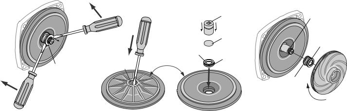
REMOVAL OF OLD SEAL
1.After unscrewing impeller, carefully remove rotating part of seal by prying up on sealing washer, using two screwdrivers (see Figure 5A). Use care not to scratch motor shaft.
2.Remove seal plate from motor and place on flat surface, face down. Use a screwdriver to push ceramic seat out from seal cavity (see Figure 5B).
INSTALLATION OF FLOATING SEAT (Figure 5C)
1.Clean polished surface of floating seat with clean cloth.
2.Turn seal plate over so seal cavity is up, clean cavity thoroughly.
3.Lubricate outside rubber surface of ceramic seat with soapy water and press firmly into seal cavity with finger pressure. If seat will not locate properly in this manner, place cardboard washer over polished face of seat and press into seal cavity using a 3/4” socket or 3/4” piece of standard pipe.
4.DISPOSE OF CARDBOARD WASHER. Be sure polished surface of seat is free of dirt and has not been damaged by insertion. Remove excess soapy water.
INSTALLATION OF ROTATING
PART OF SEAL UNIT (Figure 5D)
1.Reinstall seal plate using extreme caution not to hit ceramic portion of seal on motor shaft.
2.Inspect shaft to make sure that it is clean.
3.Clean face of sealing washer with clean cloth.
4.Lubricate inside diameter and outer face of rubber drive ring with soapy water and slide assembly on motor shaft (sealing face first) until rubber drive ring hits shaft shoulder.
5.Screw impeller on shaft until impeller hub hits shaft shoulder. This will automatically locate seal in place and move the sealing washer face up against seat facing. Reinstall impeller screw (if used).
Mechanical seal Mechanical seal stationary half rotating half
Polished surface
|
rn o |
|
|
u |
v |
||
T |
|
|
e |
|
|
r |
|
3/4" socket |
Shaft |
|
or pipe |
||
shoulder |
||
|
||
Cardboard |
Rubber drive |
|
washer |
||
(supplied w/seal) |
ring |
|
Rubber |
|
|
surface |
|
|
|
Sealing |
|
|
face |
Impeller
Seal Plate
5939 0109
A-Seal removal-rotating half |
B-Seal removal-stationary half |
C-Stationary half installation |
D-Rotating half installation |
FIGURE 5
5
 Loading...