

Snorkel T46JRT User Manual
Serial number 000000 and after
Replaces June 2012
OPERATORS
MANUAL
Part Number 1430001
December 2012


Table of Contents
Declaration of Conformity ...........................................2
Wheel Orientation Information ....................................3
Safety Rules ...............................................................4
Introduction .................................................................5
Component Identication ............................................5
Special Limitations......................................................6
Platform Capacity ....................................................6
Manual Force ..........................................................6
Platform Overload Sensing System ........................6
Beaufort Scale .........................................................6
Controls and Indicators...............................................7
Battery Disconnect Switch ..........................................8
Lower Controls ...........................................................8
Emergency Stop Button ..........................................8
Controls Selector Switch .........................................8
Preheat Button ........................................................8
Start Button .............................................................8
Ground Operation Switch ........................................8
Rotation Switch .......................................................8
Boom Elevation Switch ...........................................8
Boom Extension Switch ..........................................8
Jib Articulation Switch – T46JRT .............................8
Platform Level Switch ..............................................8
Platform Rotation Switch .........................................9
Engine/Emergency Power Switch ...........................9
Hydraulic Oil Warm-Up Switch ................................9
Circuit Breaker Reset Buttons ....................................9
Upper Controls ...........................................................9
Preheat Switch ......................................................10
Start Switch ...........................................................10
Emergency Stop Button ........................................10
Drive/Boom Selector Switch ..................................10
Drive Joystick ........................................................10
Drive Range Switch ...............................................10
Boom Joystick .......................................................10
Boom Extension Switch ........................................ 11
Jib Articulation Switch – T46JRT ........................... 11
Platform Level Switch ............................................ 11
Platform Rotation Switch ....................................... 11
Engine/Emergency Power Switch .........................11
Horn Switch ........................................................... 11
Platform Foot Switch .............................................11
AC Generator Switch ............................................ 11
Hydraulic Oil Warm-Up Switch .............................. 11
Pre-Operation Safety Inspection ..............................12
Table of Contents
System Function Inspection .....................................13
Operation ..................................................................14
Cold Weather Start-Up ..........................................14
Hydraulic System Cold Weather Warm-Up ...........14
Hydraulic System Warm-Up Switch ......................14
Manually Warming The Hydraulic System ............14
Preparing for Operation .........................................15
Lower Controls ......................................................15
Upper Controls ......................................................15
Boom Operation ....................................................15
Driving and Steering ..............................................16
Drive Speeds .........................................................17
Pivoting Front Axle ................................................17
All Motion Alarm ....................................................17
Electrical Power Outlet ..........................................17
AC Generator ........................................................17
Air Line ..................................................................17
Emergency Lowering ............................................18
Lower Controls ...................................................18
Upper Controls ...................................................18
After Use Each Day ...............................................18
Transporting the Machine .........................................19
Preparing for Transportation .................................19
By Crane ...............................................................19
By Truck ................................................................19
Storage .....................................................................19
Maintenance .............................................................20
Hydraulic Fluid ..........................................................20
Check Hydraulic Fluid ...........................................20
Engine ...................................................................20
Oil Level ................................................................20
Battery Maintenance .............................................20
Inspection and Maintenance Schedule.....................21
Daily Preventative Maintenance Checklist ...............22
Preventative Maintenance Report .........................22
Decal Location ..........................................................23
Specications – T40RT.............................................26
Specications – T46JRT ...........................................27
T40RT/T46JRT – 1430001 1
2006/42/EC
EU Vaatimustenmukaisuusvakuutus 2006/42/EC
EC-Konformitätserklärung für Maschinen 2006/42/EC
Declaration De Conformite CE pour les Machines 2006/42/EC
EC Declaration of Conformity of Machinery 2006/42/EC
CE Conformiteitsverklaring voor Machinerie 2006/42/EC
Dichiarazione Di Conformità CE Per Le Macchine 2006/42/EC
Declaracion De Conformidad CE Para Maquinaria 2006/42/EC
EF-Samsvarserklaering For Maskiner 2006/42/EC
EF-Overensstemmelseserklaering for Maskiner 2006/42/EC
EU Deklaration Avseende Överensstammelse För Maskinutrustning
Manufacturer Snorkel,
Hersteller Fabrikant Vigo Centre, Washington,
Fabricant Tillverkare Tyne and Wear, England
Fabricante Produsent Tel: +44 (0) 845 1557 755
Fabbricante Valmistaja Fax: +44 (0) 845 1557 756 Authorized Representative
Autorisierte Vertretung
Representant autorise
Representante autorizado
Mandatario
Erkend vertegenwoordiger
Auktoriserad representant
Autorisert representant
Represenentant
Valtuutettu edustaja
Description Aerial Work Platform
Bezeichnung Arbeitsbühne
Description Plate-forme elevatrice de personnel
Descripcion Platforma aerea de trabajo con motor
Descrizione Piattaforma di sollevamento motorizzata
Beschrijving Mechanisch aangedreven werkplatform
Beskrivning Höj-och sänkbar arbetsplattform
Beskrivelse Selvgående arbetsplattform
Beskrivelse Motordrevet lofteplatform
Kuvaus Konevoimalla toimiva nostolava
Selvgående personarbetslift
T40RT/T46JRT
Model Modello
Modell Verticaal model
Modele Malli
Modelo
2 T40RT/T46JRT – 1430001
Serial number Serienummer
Notified body Powered Access
Notifizierte Stelle Certification Ltd (PAC)
Organisme notifie Applethwaite Lodge, The Common
Organismo notificado Windermere
Aangemelde instantie Cumbria
Myndighet LA23 1JQ
Avendte harmoniserte standarder United Kingdom
Udpeget organ Notified body number 0545
Asiasta on tehty ilmoitus seuraaville tahoille
Ente Notificatore
EC Type Examination Certificate number
EC-Typenprufung Zertifikat-Nr
Examen type CE Numero de Certificat
Inspeccion tipo CE Numero de certificado
Attestato di certificazione CE nr
Onderzoek van het type EC Certificaatnummer
EU typkontroll Certifieringsnummer
EF-typeproving Sertifikatnummer
EF-typegodkendelse Nummer pa typeattest
EU-tyyppitarkastuksen nr.
Signed for Snorkel
Manufacturing Quality Manager Date
Gary Bradbury
Powered Access
Vigo Centre
Washington
Tyne and Wear
Matricola Numero de serie
Sarajanumero Matricola
NE38 9DA
England
WARNING
180°
21 90 mm
23 90 mm
TRA NS POR TATIO N PO S ITI ON
W OR KING/ EL EVATI NG P OS IT ION
SAFETY NOTICE
PLEASE READ BEFORE USE
If this machine has been transported in a container the wheels will have been
flipped to get it into the container. This will make the machine narrower than the
design intent. The machine may be driven with the wheels flipped to load &
unload but only ever when in the stowed position. The machine must not be
used for a job of work until the wheels have been flipped back round to their
correct position.
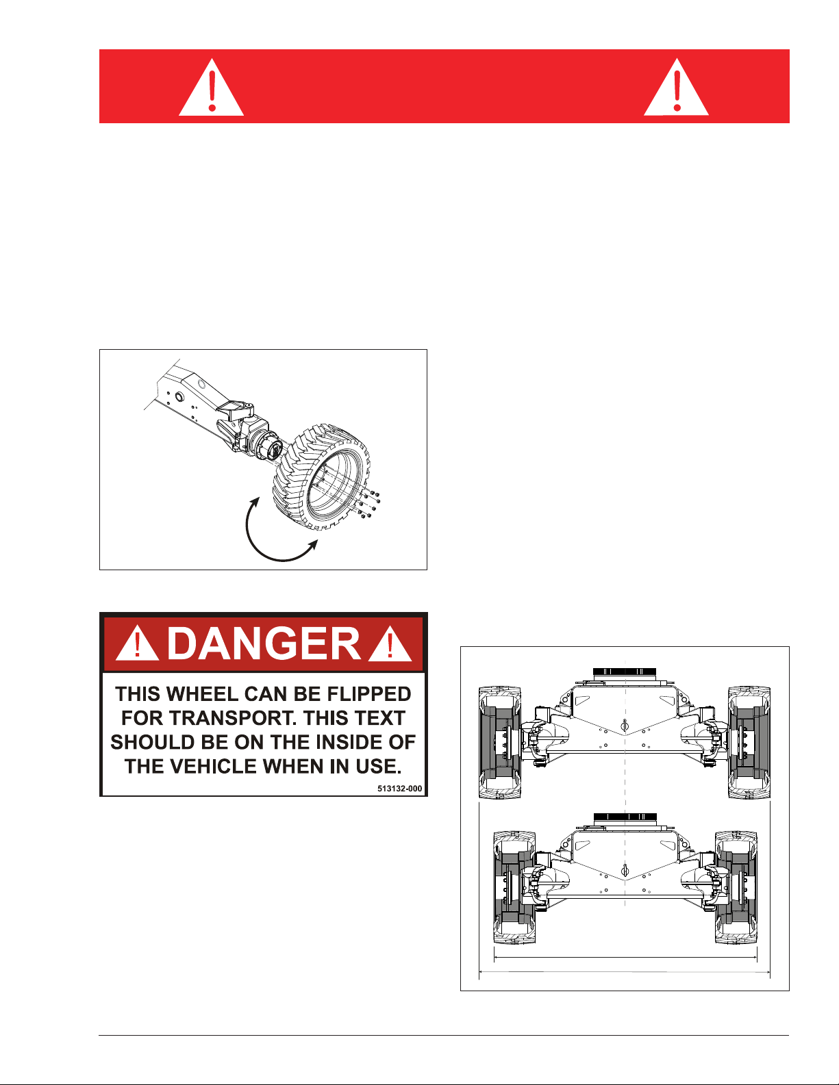
To flip the wheel back to the correct orientation (refer to
Figure 1), use the following instructions.
1. Safely jack the machine.
2. Loosen the 9 retaining lug nuts.
3. Safely remove the wheel from the hub.
4. Flip the wheel 180° so that decal 513132-000 is facing
on the inside of the wheel. Refer to Figure 2.
Figure 1 – Correct Wheel Orientation
Figure 2 – Wheel Position Decal
The distance between the outer edge of the right wheel
to the outer edge of the left wheel should be 2390mm
(94 in) when the wheels are correctly orientated. Refer
to Figure 3.
5. Safely fit the wheel back onto the hub.
6. Hand tighten the 9 retaining lug nuts and lower the
machine from the jack.
7. Dry torque the lug nuts to 150 ft lbs in a non-circular
pattern.
T40RT/T46JRT – 1430001 3
Figure 3 – Wheel Position Distance
Introduction
U
p
R
i
g
h
t
A
B
3
8
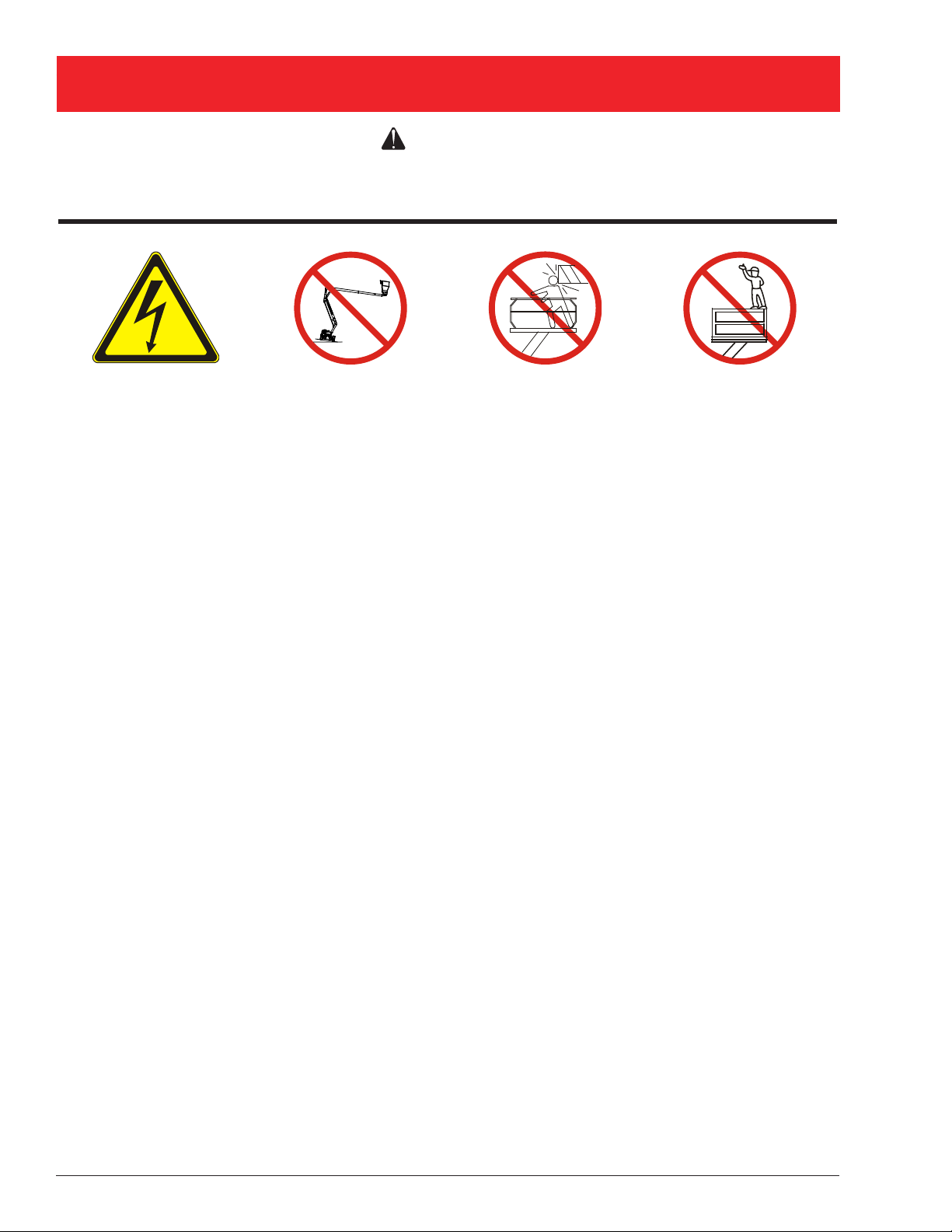
SAFETY RULES
Warning
All personnel shall carefully read, understand and follow all safety rules and operating instructions
before operating or performing maintenance on any Snorkel aerial work platform.
Electrocution Hazard Tip Over Hazard Collision Hazard Fall Hazard
THIS MACHINE IS
NOT INSULATED!
NEVER elevate the platform
or drive the machine while
elevated unless the machine
is on a firm, level surface
NEVER position the platform
without first checking for
overhead obstructions or
other hazards.
NEVER climb, stand, or sit
on platform guardrails or
midrail.
USE OF THE AERIAL WORK PLATFORM: This aerial work platform is intended to lift persons and his tools as well as the
material used for the job. It is designed for repair and assembly jobs and assignments at overhead workplaces (ceilings,
cranes, roof structures, buildings etc.). Uses or alterations to the aerial work platform must be approved by Snorkel.
THIS AERIAL WORK PLATFORM IS NOT INSULATED! Refer to applicable national/governmental/local regulations for safe
approach distances.
Exceeding the specied permissible maximum load is prohibited! See “Platform Capacity” on page 6 for details.
The use and operation of the aerial work platform as a lifting tool or a crane is prohibited!
NEVER exceed the manual force allowed for this machine. See “Manual Force” on page 6 for details.
DISTRIBUTE all platform loads evenly on the platform.
NEVER operate the machine without rst surveying the work area for surface hazards such as holes, drop-offs, bumps, curbs,
or debris; and avoiding them.
OPERATE machine only on surfaces capable of supporting wheel loads.
NEVER operate the machine when wind speeds exceed this machine’s wind rating. See “Beaufort Scale” on page 6 for details.
Do not operate the aerial platform in windy or gusty conditions. Do not add anything to the aerial platform that will increase the
wind loading such as billboards, banners, flags, etc.
IN CASE OF EMERGENCY push EMERGENCY STOP switch to deactivate all powered functions.
IF ALARM SOUNDS while platform is elevated, STOP, carefully lower platform. Move machine to a rm, level surface.
Climbing up the railing of the platform, standing on or stepping from the platform onto buildings, steel or prefab concrete
structures, etc., is prohibited!
Dismantling the entry gate or other railing components is prohibited! Always make certain that the entry gate is closed!
It is prohibited to keep the entry gate in an open position when the platform is raised!
To extend the height or the range by placing of ladders, scaffolds or similar devices on the platform is prohibited!
NEVER perform service on machine while platform is elevated without blocking elevating assembly.
INSPECT the machine thoroughly for cracked welds, loose or missing hardware, hydraulic leaks, loose wire connections, and
damaged cables or hoses before using.
VERIFY that all labels are in place and legible before using.
NEVER use a machine that is damaged, not functioning properly, or has damaged or missing labels.
To bypass any safety equipment is prohibited and presents a danger for the persons on the aerial work platform and in its
working range.
NEVER charge batteries near sparks or open ame. Charging batteries emit explosive hydrogen gas.
Modications to the aerial work platform are prohibited or permissible only at the approval by Snorkel.
AFTER USE, secure the work platform from unauthorized use by turning the keyswitch off and removing key.
The driving of MEWP’s on the public highway is subject to national trafc regulations.
Certain inherent risks remain in the operation of this machine despite utilizing proper design practices and safeguarding.
Harness attachment points are provided in the platform and the manufacturer recommends the usage of a fall restraint
harness, especially where required by national safety regulations.
Care must be taken to ensure that the machines meets the requirements of stability during use, transportation, assembly,
dismantling when out of service, testing, or foreseeable breakdowns.
In the event of an accident or breakdown see “Emergency Lowering” on page 17, do not operate the aerial platform if it is
damaged or not functioning properly. Qualied maintenance personnel must correct the problem before putting the aerial
platform back into service.
4 T40RT/T46JRT – 1430001
Introduction
Introduction
This manual covers the T40RT and T46JRT Aerial Work
Platforms.
This manual must be stored on the machine at all
times.
Read, Understand and follow all safety rules and operating instructions before attempting to operate the
machine.
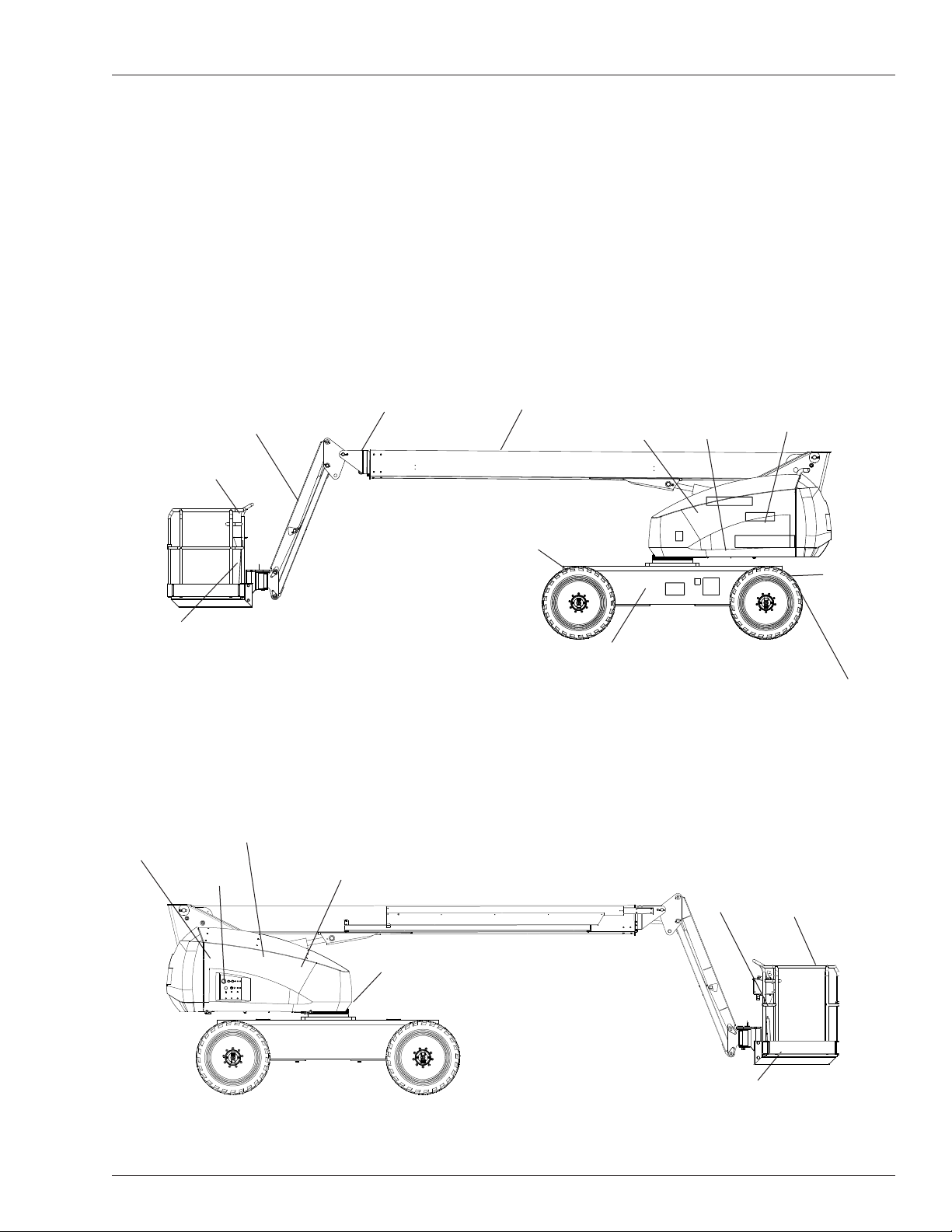
Component Identication
Jib
T46JRT Only
Upper Controls
Tip Boom
Tie-Down/Lifting Lugs
Top Rear of Chassis
When contacting Snorkel for service or parts information,
be sure to include the MODEL and SERIAL NUMBERS
from the equipment nameplate. Should the nameplate
be missing, the SERIAL NUMBER is also stamped at
the rear of the chassis.
Main Boom
Battery
Battery
Disconnect
Engine
Pivoting
Front Axle
Operator’s
Manual
Fuel Tank
Hydraulic Fluid Tank
Lower
Controls
Hydraulic Fluid Filter
Nameplate Location
Right Side
Chassis
Rear Front
Steer Wheels
Tie-Down/Lifting Lugs
Lanyard
Anchors
Top Front of Chassis
Platform
Platform
Steer Wheels
Front
Rear
Foot Switch
Left Side
T40RT/T46JRT – 1430001 5

Special Limitations
Special Limitations
Travel with the platform raised is limited to creep speed
range. Elevating the platform is limited to firm, level
surfaces only.
Danger
The elevating function shall ONLY be used when the
work platform is level and on a firm surface.
The work platform is NOT intended to be driven over
uneven, rough, or soft terrain.
Platform Capacity
Two people and tools may occupy the platform. The maximum platform capacity for the aerial platform is stated in
the “Specifications” on pages 26 and 27.
Danger
DO NOT exceed the maximum platform capacity or
the platform occupancy limits for this machine.
Manual Force
Manual force is the force applied by the occupants to
objects such as walls or other structures outside the
work platform.
The maximum allowable manual force is limited to 200 N
(45 lbs) of force per occupant, with a maximum of 400 N
(90 lbs) for two occupants.
The system will remain in error mode until the excess
load is removed from the platform and the emergency
stop button or start switch is cycled off and back on,
resetting the system. At that time, the machine functions
are operational.
Caution
The emergency power system is for emergency lowering and stowing only. The length of time the pump
can be operated depends on the capacity of the battery. Do not use this system for normal operation.
If the platform overload sensing system is tripped while
operating the machine or if the system is in error mode
and can not be reset, the emergency power system may
still be used for emergency machine operation from either
the lower or upper controls.
Danger
The aerial platform can tip over if it becomes unstable.
Death or serious injury will result from a tip-over accident. Do not exceed the capacity values indicated
on the platform rating placard.
The overload sensing system is not active when the
machine is being driven with the booms in the stowed
position. This allows the machine to be driven without
the system sensing an overload due to rough ground
conditions.
Danger
DO NOT exceed the maximum amount of manual
chine operation, there is a five second delay in machine
functions following:
force for this machine.
To eliminate repeated tripping of the system during ma-
starting the engine.
•
Platform Overload Sensing System
All functions are stopped from the upper and lower controls, when the platform overload limit is exceeded. The
horn will sound intermittently and the platform overload
placing the drive/boom selector switch in the boom
•
position when the main boom is below horizontal and
fully retracted.
light will blink until the excess load is removed from the
platform. At that time, the machine functions are again
removing excess load from the platform.
•
operational.
Beaufort Scale
If the platform becomes significantly overloaded, or if an
upward force on the platform exceeds approximately 2225
Never operate the machine when wind speeds exceed
12.5 m/s (28mph) [Beaufort scale 6]. Refer to Figure 1.
N (500 lb), the system will enter into error mode, stopping
all functions from the upper and lower controls. The horn
will then sound constantly and the overload light will stay
illuminated at the upper and lower controls.
BEAUFORT
RATING
3 3,4~5,4 12,25~19,4 11.5~17.75 7.5~12.0 Papers and thin branches move, ags wave.
4 5,4~8,0 19,4~28,8 17.75~26.25 12.0~18 Dust is raised, paper whirls up, and small branches sway.
5 8,0~10,8 28,8~38,9 26.25~35.5 18~24.25
6 10,8~13,9 38,9~50,0 35.5~45.5 24.5~31
7 13,9~17,2 50,0~61,9 45.5~56.5 31.~38.5 Whole trees sway. It is difcult to walk against the wind.
m/s km/h ft/s mph
WIND SPEED
GROUND CONDITIONS
Shrubs with leaves start swaying. Wave crests are apparent in ponds
or swamps.
Tree branches move. Power lines whistle. It is difcult to open an
umbrella.
Figure 1 – Beaufort Scale
6 T40RT/T46JRT – 1430001
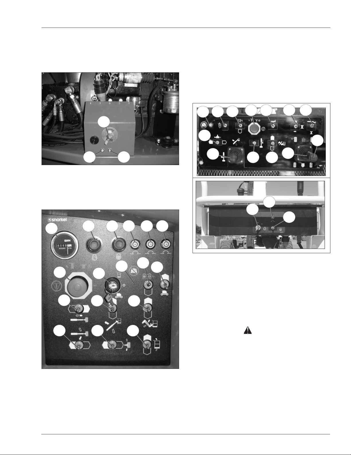
Controls and Indicators
Controls and Indicators
The operator shall know the location of each control and
indicator and have a thorough knowledge of the function
and operation of each before attempting to operate the
machine.
1
2
Figure 2 – Battery Disconnect Switch
1. Battery disconnect switch
2. Glow plugs circuit breaker
3. Throttle circuit breaker
5
6
7
3
8 9
10
11. Controls selector switch
12. Ground operation switch
13. Platform overload light
14. Engine/emergency power switch
15. Boom extension switch
16. Boom elevation switch
17. Jib articulation switch – T46JRT
18. Rotation switch
19. Platform rotation switch
20. Platform level switch
21
13
19
24
20
14
4
15
6
17
27
22 23
26
25
28
13
4
15
18
Figure 3 – Lower Controls and Indicators
4. Emergency stop button
5. Hour meter
6. Start switch
7. Preheat button
8. Main system circuit breaker
9. Relays/sensors circuit breaker
10. Boom functions circuit breaker
16
19
11
17
20
14
12
Figure 4 – Upper Controls and Indicators
21. Horn switch
22. Drive range switch
23. Drive/boom selector switch
24. Boom joystick
25. Drive joystick
26. Steer switch
27. Upper control circuit breaker
28. Preheat switch
Danger
Pinch points may exist between moving components.
Death or serious injury will result from becoming
trapped between components, buildings, structures,
or other obstacles. Make sure all personnel stand
clear while operating the aerial platform.
Controls to position the platform are located on the
•
lower control panel on the turntable and on the upper
control panel in the platform.
Controls to drive the aerial platform are located on the
•
upper control panel only.
T40RT/T46JRT – 1430001 7
 Loading...