


14U454B
Table of contents
 Loading...
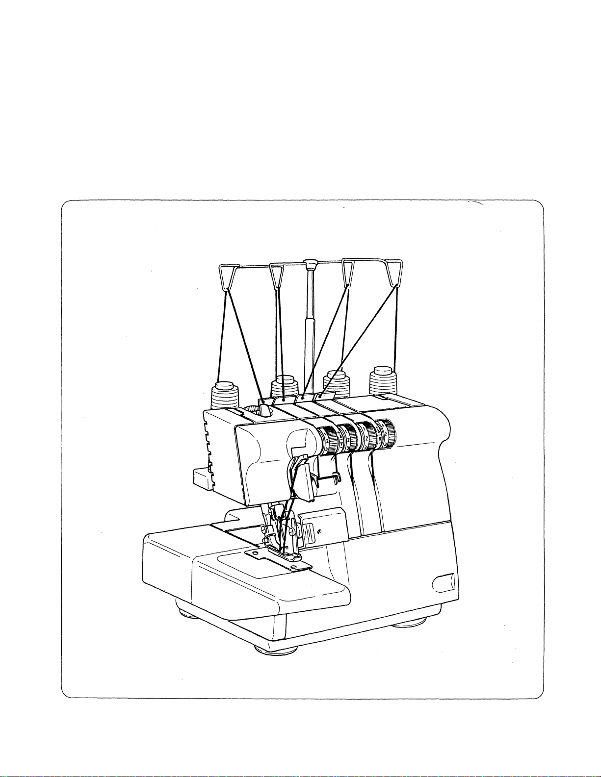
14
3-4THREAD OVERLOOK MACHIIME
U444B/454B
Operator’s
Guide
SINGER

14U 444B/454B
PREFACE
Thank you for your purchase of this sewing machine.
This machine intended for household use will provide you with excellent performance in sewing from light
to heavy material (lawn to denim). Please refer to this booklet for proper use and optimum service. To
get the most out of your sewing machine, read the entire operator’s manual before attempting to operate
the machine. Then familiarize yourself with the machine by following the operator’s manual page by page.
To ensure that you are always provided with the most modern sewing capabilities, the manufacturer
reserves the right to change the appearance, design or accessories of this sewing machine when considered
necessary without notification or obligation.
SINGER CUSTOMER ASSISTANCE IN THE U.S.A.
TOLL-FREE NUMBER: 1-800-877-7762
Copyright ©1993 THE SINGER COMPANY
All Rights Reserved Throughout The World

IMPORTANT SAFETY INSTRUCTIONS
When using this machine, basic safety precautions should always be followed including the following.
Read all instructions before using this machine.
DANGER
The machine should never be left unattended when plugged in. Always unplug the machine from the
electric outlet immediately after using and before cleaning.
Always unplug before relamping. Replace bulb with the same type rated 12 volt, 6 watts. Be sure to
replace the face plate which covers the light bulb before operating the machine.
WARNING
Be sure that the electrical voltage of the socket outlet (wall receptacle) is the same as the rated voltage
of the motor.
Use this machine only for its intended use as described in this Operator’s Guide. Use only attachments
recommended by the manufacturer as contained in the Operator’s Guide.
To disconnect, turn all controls to the off (“0”) position, then remove plug from outlet.
Disconnect the power line plug from the socket outlet or switch the machine off when making any
adjustments in the needle area, such as threading needle and loopers, changing needle, changing throat
plate or changing presser foot, etc.
Always unplug the machine from the electrical outlet when removing covers, lubricating, or when
making any other user servicing adjustments mentioned in the Operator’s Guide.
“ To reduce the risk of electric shock:
— To reduce the risk of burns, fire, electric shock or injury to persons:
Do not attempt to adjust the motor belt. Contact your nearest Service Center should any adjustment
be required.
Do not unplug by pulhng on cord. To unplug, grasp the plug, not the cord.
Handle the foot controller with care and avoid dropping it on the floor. Be sure not to place anything
on top of it.
Always use the proper throat plate. The wrong plate can cause the needle to break.
Do not use bent needles.
When sewing, keep fingers away from all moving parts. Special care is required around the sewing
machine needle.
Do not pull or push fabric while stitching. It may deflect the needle causing it to break.
For double insulated machines, when servicing use only identical replacement parts. See instructions
for Servicing of Double-Insulated Appliances.
Use only the handle to lift and move the machine.
Never operate the machine if it has a damaged cord or plug, if it is not working properly, if it has been
dropped or damaged, or dropped into the water. Return the machine to the nearest authorized dealer
or Service Center for examination, repair, electrical, or mechanical adjustment.
Never operate the machine with any air openings blocked. Keep ventilation openings of the machine
and foot controller free from the accumulation of lint, dust, and loose cloth.

■ Never drop or insert any object into any opening.
■ Do not use outdoors.
■ Do not operate where aerosol ( spray) products are being used or where oxygen is being administered.
■ Do not allow to be used as a toy. Close attention is necessary when the machine is used by or near
children.
■ Do not expose the machine or machine plastic case to sunlight directly. Also, do not keep it in a very
warm or damp place.
■ SERVICING OF DOUBLE-INSULATED PRODUCTS. In a double-insulated product, two systems
of insulation are provided instead of grounding. No grounding means is provided on a double-insulated
product, nor should a means for grounding be added to the product. Servicing of a double-insulated
product requires extreme care and knowledge of the system, and should be done only by qualified
service personnel. Replacement parts for a double- insulated product must be identical to those parts
in the product. A double-insulated product is marked with the words “DOUBLE-INSULATION” or
“DOUBLE-INSULATED.”
SAVE THESE INSTRUCTIONS
Servicing should be performed by an authorized service representative.
This product is intended for household use.
FOR EUROPEAN AND SIMILAR TERRITORIES:
This product is suppressed for radio and television interference with the International Electrotechnical
Commission requirements of the CISPR.
Machines for Great Britain and some other countries having similar wiring standards are shipped from
the factory without a plug for connection to the mains. The wires in this mains lead are colored in accord
ance with the following code.
Blue: neutral (N) Brown: live (L)
As the colors of the wires in the mains lead of this appliance may not correspond with the colored markings
identifying the terminals in your plug, proceed as follows:
The wire which is colored blue must be connected to the terminal which is marked with the letter N or
colored black. The wire which is colored brown must be connected to the terminal which is marked with
letter L or colored red. If a 13 Amp. (BS 1363) plug is used, a 3 Amp. fuse must be fitted, or if any other
type of plug is used, a 5 Amp. fuse must be fitted either in the plug or adaptor or at the distribution board.
Neither cord is to be connected to the earth terminal of a three-pin plug.

CONTENTS
Page
1. Accessories
2. Needle information
3. Principal parts
4. How to open looper cover................................6
5. Principal parts behind looper cover
6. Preparation prior to sewing..............................6
7. Setting up the thread guide holder
8. How to remove and insert needle
• To remove needle (s)
• To insert needle (s)
9. How to remove and replace
cloth plate....................................................9
10. How to remove and replace
cylinder cover..............................................9
11. Threading the machine....................................10
• Threading diagram
• Understanding the color code
• Stitch diagram
• To thread the machine correctly
• Important threading information
12. Chaining off and test sewing
13. Basic stitch types
• 4 thread overlock
• Wide 3 thread overlock stitch
• Narrow 3 thread overlock stitch
14. How to adjust thread tension
• Suggested tension settings for 4 thread
• Correct balance of the 4 thread
• How to balance the 4 thread
• Suggested tension setting for the
• Correct balance of the 3 thread
• How to balance the 3 thread
15. How to change threads/tie on method ... .22
16. How to adjust the stitch length
17. How to disengage movable upper knife ... .23
• To place movable knife in
• To place movable knife in working
.....................................................
..........................................
..................................................
.................
...................
....................
..................................
.....................................
....................................
...................
...........................................
...............
..............
.........................
...........................................
mock safety stitch...................................19
...................
...............
.........................
overlock mock safety stitch
overlock mock safety stitch
overlock mock safety stitch
3 thread overlock stitch
overlockstitch
overlockstitch
nonworking position...............................23
position
.........................................
.........................................
...................................................
....................
....................
....................
..........................
......................
4
10
10
10
10
17
18
19
19
19
19
20
20
20
21
21
21
23
24
Page
18. Seam guide lines
4
5
6
7
8
8
8
19. How to adjust the overedge
seam width ..................................................25
20. How to sew a rolled hem .
• Machine set up
• Suggested tension settings for
standard rolled hem.................................27
• Suggested tension settings for upper
looper thread wrapped rolled hem ... .27
• How to balance the upper looper
thread wrapped rolled hem
• Additional information about
rolled hemming
• To secure the rolled hem thread
chain .......................................................28
21. Stitch variations and sewing
techniques
• How to sew a flatlock decorative
seam
........................................................
• How to sew an overlock blind hem
• How to sew pin tucks
• Turning square corners
• Pin placement ...........................................33
• Securing the thread chain
• Applying elastic
• How to reinforce a seam
• Braiding by chaining off
• Differential feed (with differential
feed machine only)..................................36
22. How to adjust the presser foot pressure ... .38
23. Free arm sewing.............................................38
24. Relationship between cloth, thread
and needle
25. Machine maintenance
• Cleaning the machine ...............................40
• Oiling the machine
• How to replace the stationary knife ... .41
• How to exchange light bulb
26. Troubleshooting chart
27. Optional accessories and attachments
28. Specification
...........................................
...
.........................
..........................................
.....................
......................................
...............................................
..........
..............................
............................
.........................
........................................
..........................
...........................
...............................................
...................................
....................................
.....................
....................................
...........
..................................................
.24
26
26
27
28
29
29
31
31
32
33
34
35
35
39
40
40
42
43
44
45
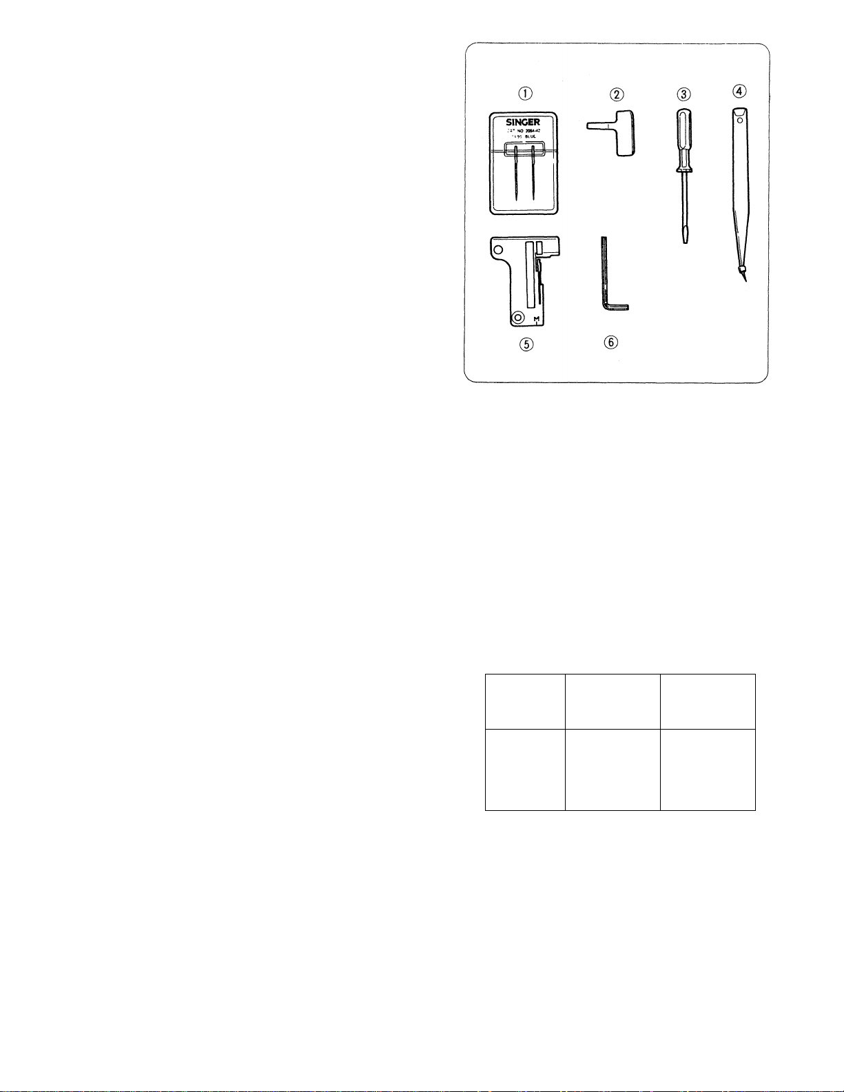
1. ACCESSORIES
Needle set 1
Screwdriver (sheet metal) 1
Screwdriver (small size) 1
Tweezers 1
©
Rolled hemming throat plate 1
Hex-head wrench 1
See page 44 for optional accessories.
2. NEEDLE INFORMATION
* This overlock uses a flat shank industrial needle
that eliminates the possibility of inserting the
needle backwards.
* Do not attempt to use a standard household
sewing machine needle of any size or type in this
overlock.
* Singer needle #2054 size 14 is furnished with the
machine. Regular point needles (#2054-42) for
sewing woven fabrics and ball point needles
(2054-06) are available for sewing knits. Both
types are available in sizes 10, 12, 14 & 16.
* Refer to the chart on page 39 for selecting the
correct needle for your sewing projects.
#2054
Overlook needle
Sizes
available
Household needle
Regular Point
wovens
#2054-42
10
12
14
16
#2045
Ball Point
knits
#2054-06
10
12
14
16
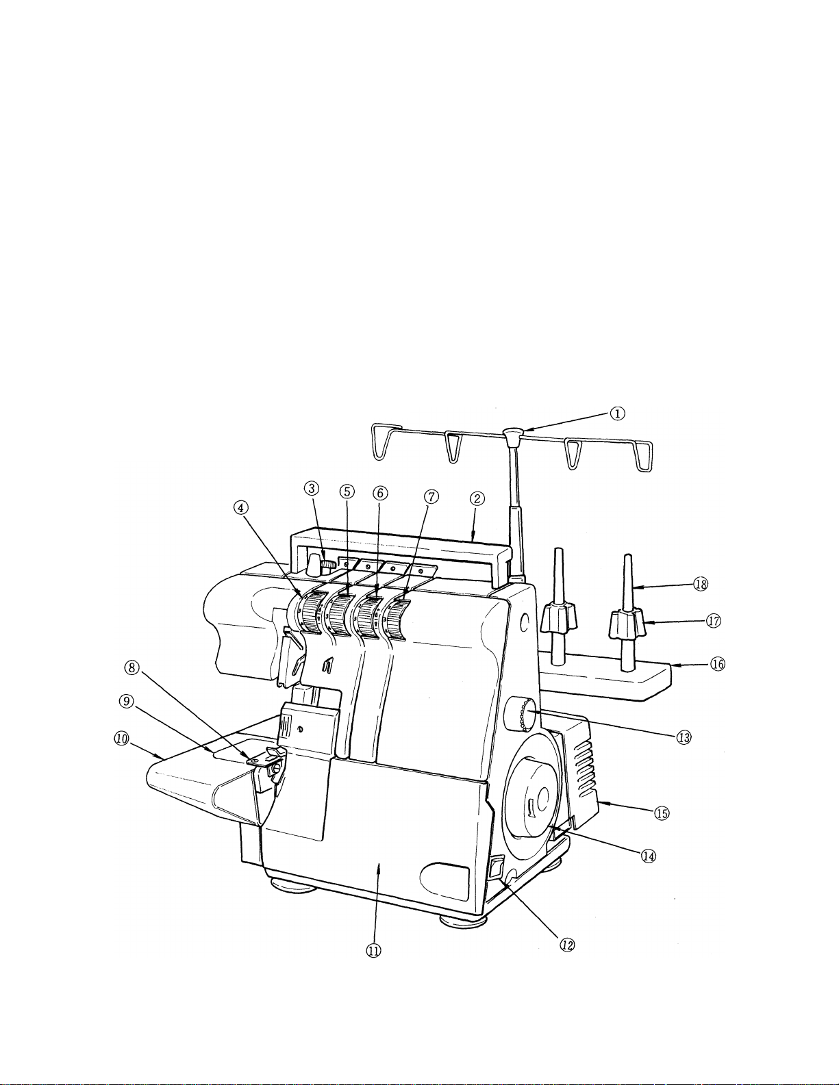
3. PRINCIPAL PARTS
(D Thread guides and holder
(2) Handle
(D Pressure regulating screw
® Left needle thread tension dial (blue)
(D Right needle thread tension dial (green)
® Upper looper thread tension dial (orange)
(7) Lower looper thread tension dial (yellow)
(8) Throat plate
® Cylinder cover
® Cloth plate
© Looper cover
® Power & light switch
® Stitch length dial
® Hand wheel
® Motor cover
® Spool stand
Cone adapter
Spool pin
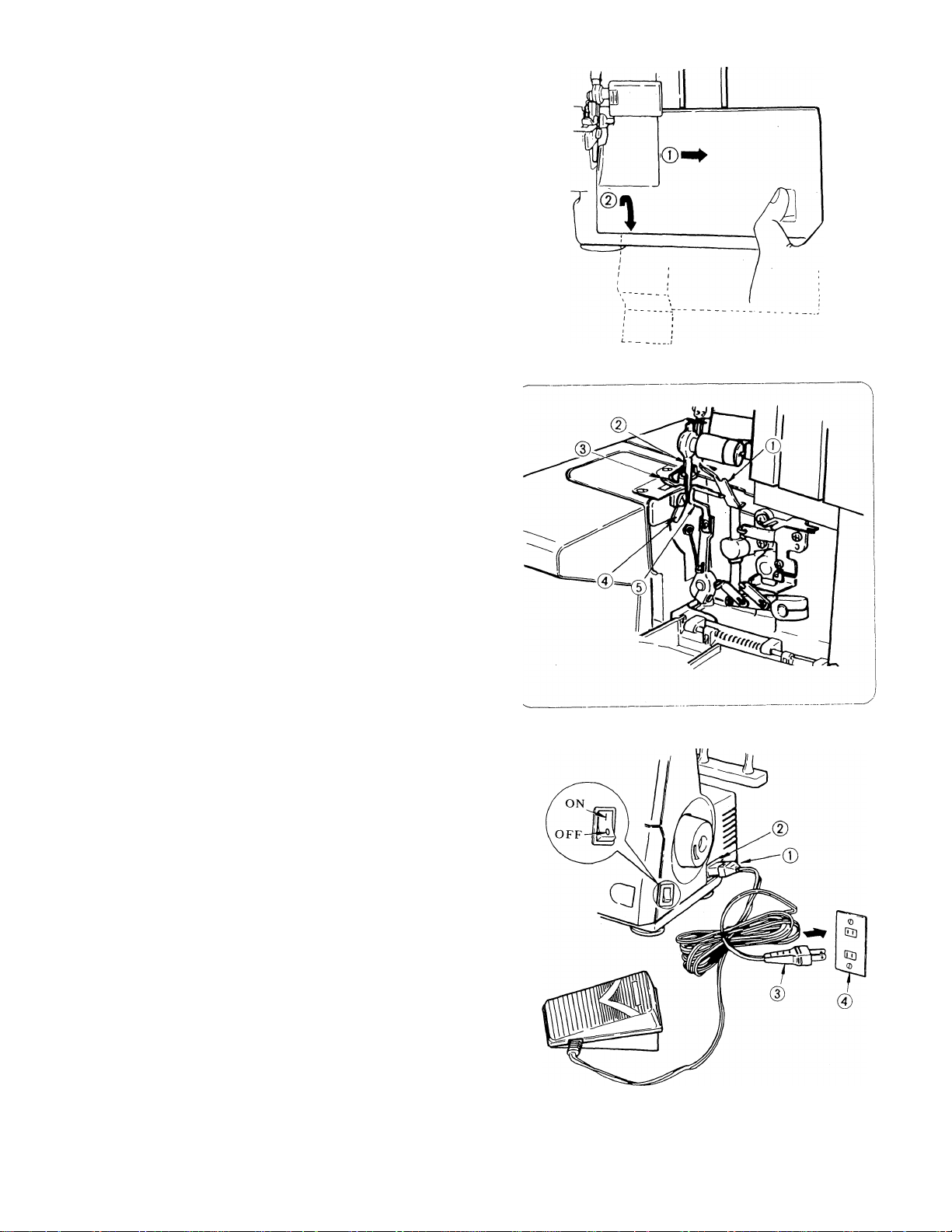
4. HOW TO OPEN LOOPER COVER
* Push the cover to the right as far as it will go. 0
* Pull cover down toward you. @
Caution:
Be sure looper cover is closed when sewing.
5. PRINCIPAL PARTS BEHIND LOOPER
COVER
0 Upper looper
0 Movable upper knife
0 Presser foot
0 Stationary lower knife
© Lower looper
6. PREPARATION PRIOR TO SEWING
* Connect the controller/electric plug 0 to the
machine receptacle © .
* Plug power line @ into electric outlet © .
* Power switch Push ‘‘I” mark side
(used also for light switch) to turn “ON”
I Push “0” mark side
to turn “OFF”
* To run the machine and control the speed, press
the controller.
* The harder you press, the faster the machine will
sew.
* To stop the machine from sewing, remove your
foot from the controller.
Be sure to make reference to "Warning'
on following page.
Warning:
Be sure that the electrical voltage of the electric outlet (wall receptacle) is the same as the rated
voltage of the motor.
* Handle the foot controller with care and avoid dropping it on the floor. Be sure not to place
anything on top of it when not in use.
* Disconnect the powerline plug from the electric outlet when changing needles, presser feet or
throat plates, or when leaving the machine unattended. This eliminates the possibility of starting
the machine by accidentally pressing the controller.
* Before'cleaning your machine, disconnect the powerHne plug from the electric outlet.
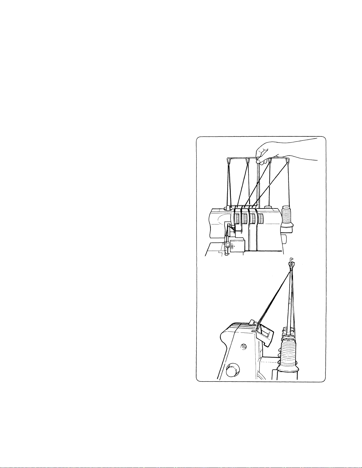
7. SETTING UP THE THREAD GUIDE
HOLDER
* This machine is shipped with the thread guide
holder in the lowered position.
* Fully extend the thread guide holder.
* The two joints on the telescope will cHck into
place when they are correctly positioned.
* Center the thread guides above the spool pins.
* Place thread over the cone adapters on the spool
pins.
Note: If the machine is threaded, straighten the
threads to prevent tangling.
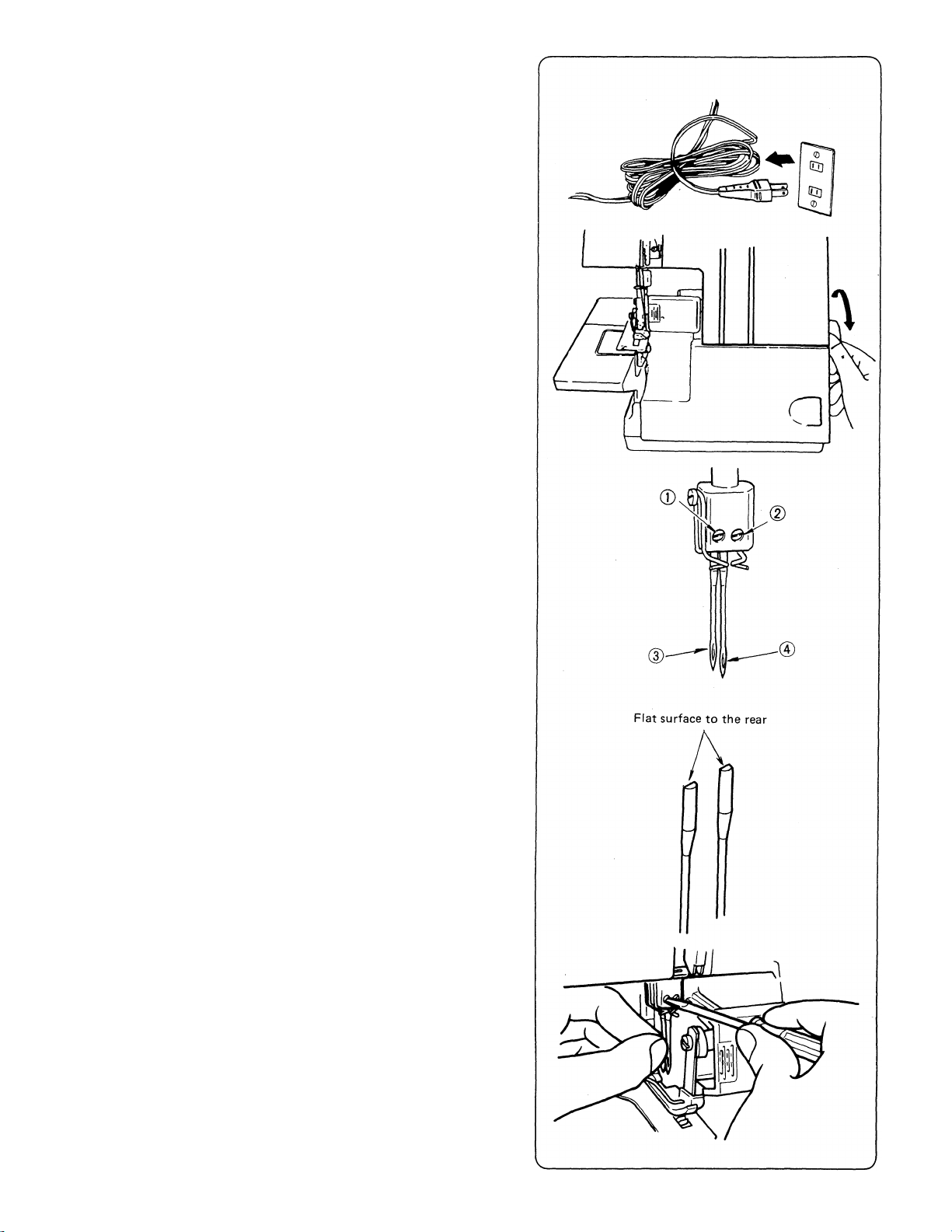
8. HOW TO REMOVE AND INSERT
NEEDLES
• TO REMOVE NEEDLE (S)
* Be sure to disconnect the machine from the
electric outlet before removing needle(s).
* Turn the hand wheel toward you until the needle
is at its highest position.
* Loosen, but do not remove the needle set screw
with the small screwdriver.
- left needle set screw 0
— right needle set screw @
* Remove the needle(s).
* TO INSERT NEEDLE (S)
* Hold the needle with the flat surface to the back.
* Insert the needle into the needle clamp as far as it
will go.
Note: The left needle @ will be slightly higher
than the right needle ® .
* Securely tighten the needle set screw.
Note:
* This machine uses #2054 needles. Refer to
page 4 for additional needle information.
* Remove the cloth plate or the cylinder cover
if you find it difficult to remove and replace
the needle.
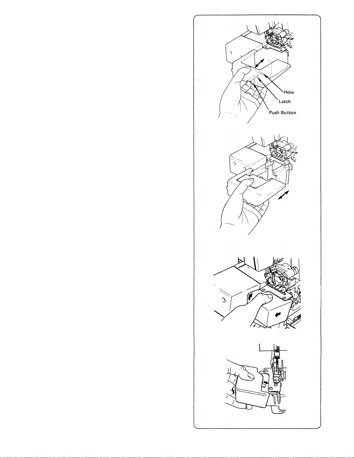
9. HOW TO REMOVE AND REPLACE
CLOTH PLATE
* Remove cloth plate for free arm sewing
(tublar work)
* To remove, pull cloth plate to the left while
pressing the push botton on underside of cloth
plate upward.
* To replace, guide latch on cloth plate into hole
in cylinder cover and push cloth plate to the
right as far as it will go.
10. HOW TO REMOVE AND REPLACE
CYLINDER COVER
* Removing the cylinder cover exposes the lower
looper for easy threading and cleaning of the
machine.
* Cylinder cover can be removed together with
the cloth plate by pulling the cylinder cover
to the left.
* To replace the cylinder cover together with the
cloth plate, push cloth plate with the cylinder
cover attached, to the right as
* To remove the cylinder cover when cloth plate
is not fitted on the machine, it can be removed
easily by lifting it upward while pulling to the
left.
* To replace only the cylinder cover, place tab on
top of cylinder cover under the throat plate
and press cover downward and to the right.
far as it will go.
Warning:
Do not hold the cylinder cover when lifting or
carrying the machine.
Caution:
Be sure cylinder coveris replaced when sewing.
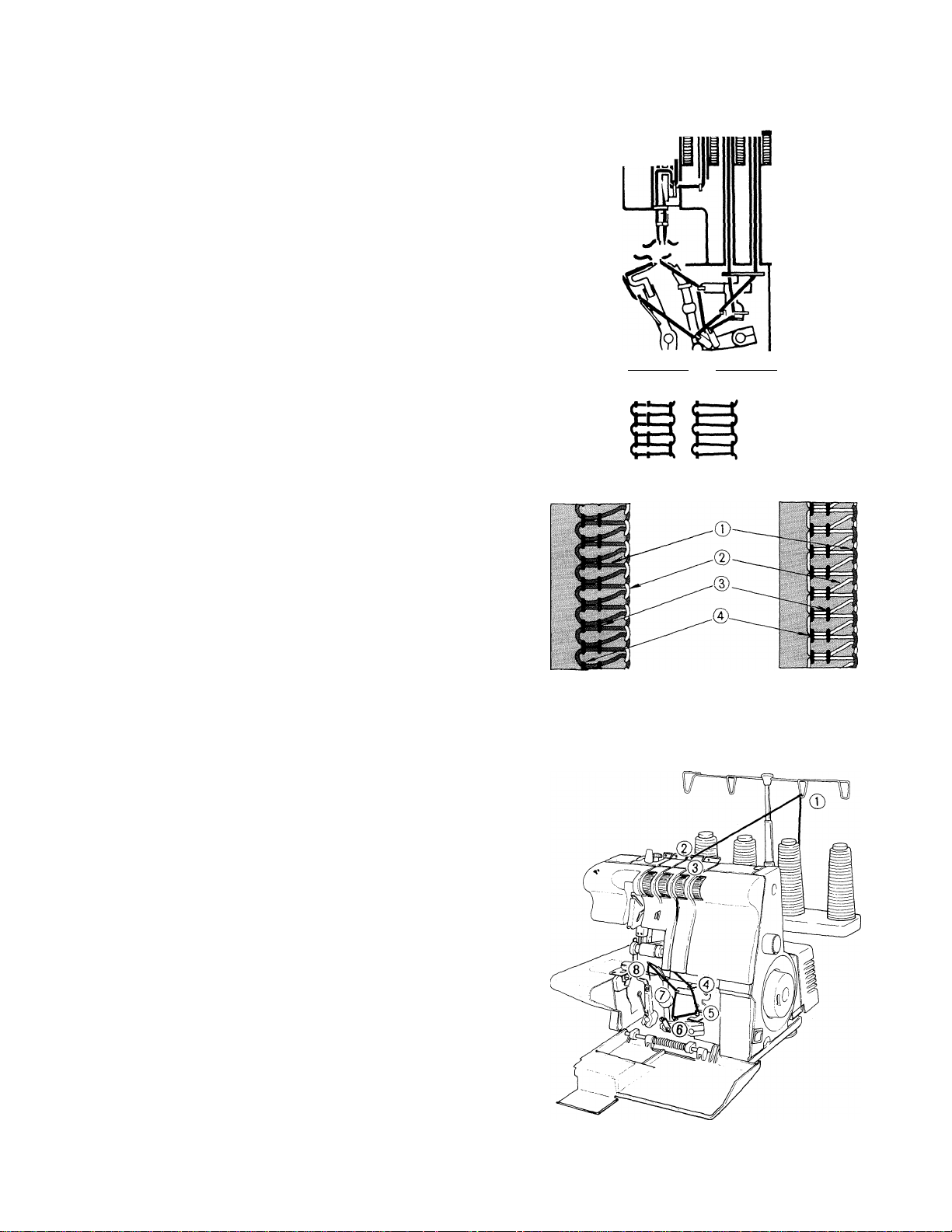
11. THREADING THE MACHINE
• THREADING DIAGRAM
* A color coded threading diagram is located inside
the looper cover for quick reference.
* Thread the machine in the order 0 to @ as
shown.
* UNDERSTANDING THE COLOR CODE
* Left needle thread — Blue ®
* Right needle thread - Green @
* Upper looper thread — Orange 0
* Lower looper thread — Yellow 0
STITCH DIAGRAM
d“
4 THREADS
0 @ ® (D
3 THREADS
LEFT RIGHT
NEEDLE NEEDLE
~ Orange
~ Yellow
* Right needle thread
* Left needle thread ~ Blue
— Green
~ Blue
©
@
©
0
• TO THREAD THE MACHINE
CORRECTLY
(1) Threading the Upper Looper (Orange)
* Thread the upper looper as indicated ® ®
Topside
Underside
10
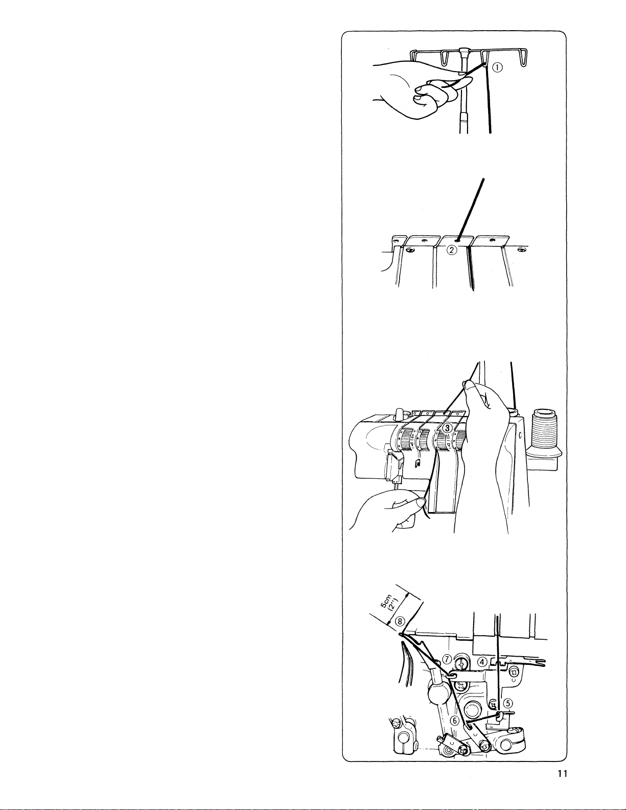
* Pass thread from back to the front through the
thread guide ® .
* Pass thread through hole (2) from front to back,
then to the front through right slot as shown.
* While holding thread with finger, pass it between
the tension discs and pull thread down to make
certain it is properly located in between the
tension discs.
* Thread the looper area of the machine following
the orange color coded thread guides. (0'^@)
* Thread the hole in the upper looper from front to
back®.
Note: Use the tweezers provided in the accessory set
to aid in threading the looper.
* Pull about 5 cm (2 inches) of thread through the
looper and place to the back of the throat plate.
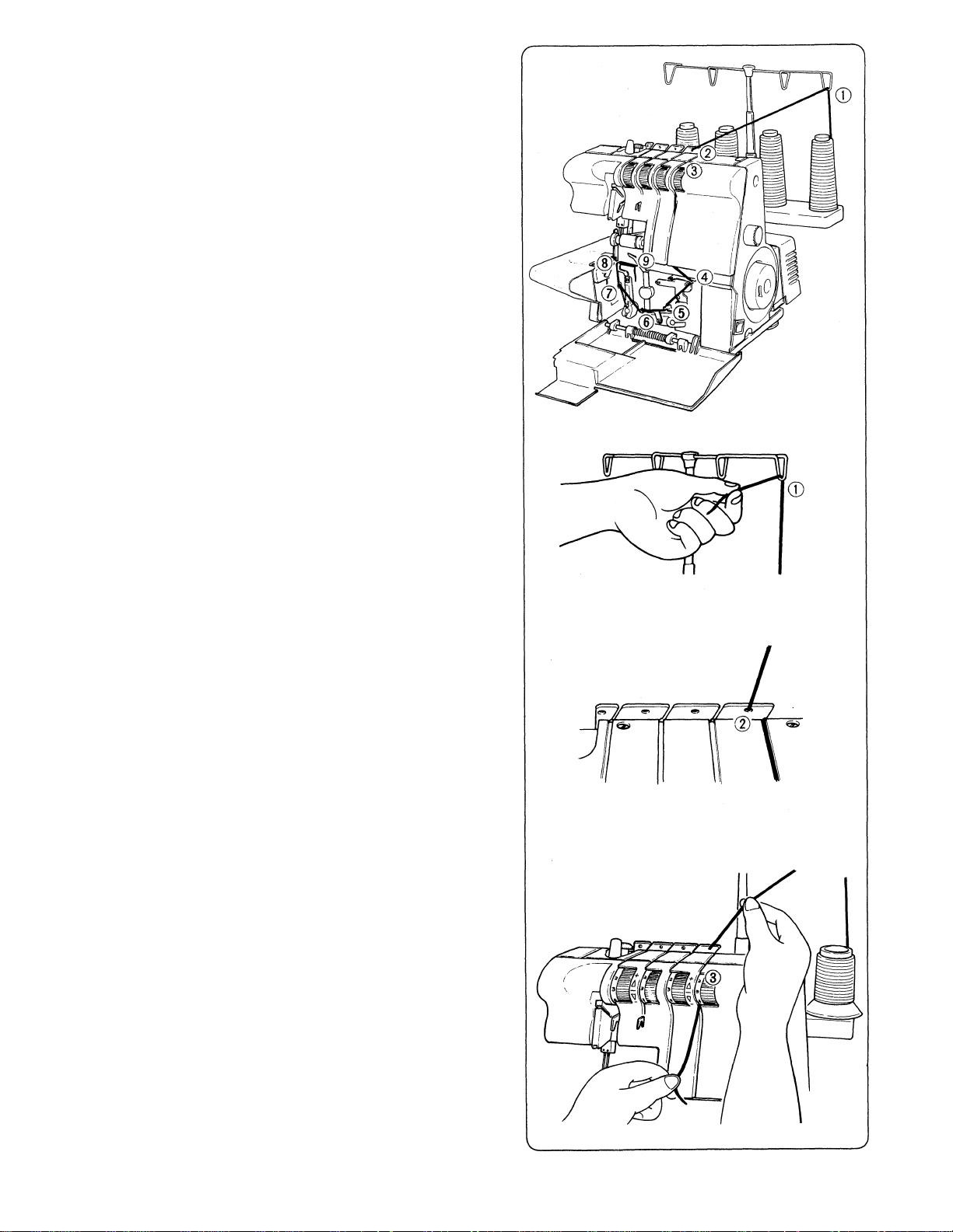
(2) Threading the Lower Looper (Yellow)
* Thread the lower looper as indicated ©
Pass thread from back to the front through the
thread guide ® .
Pass thread through hole @ from front to back,
then to the front through right slot as shown.
* While holding thread with finger, pass it between
the tension discs and pull thread down to make
certain it is properly located in between the
tension discs.
12
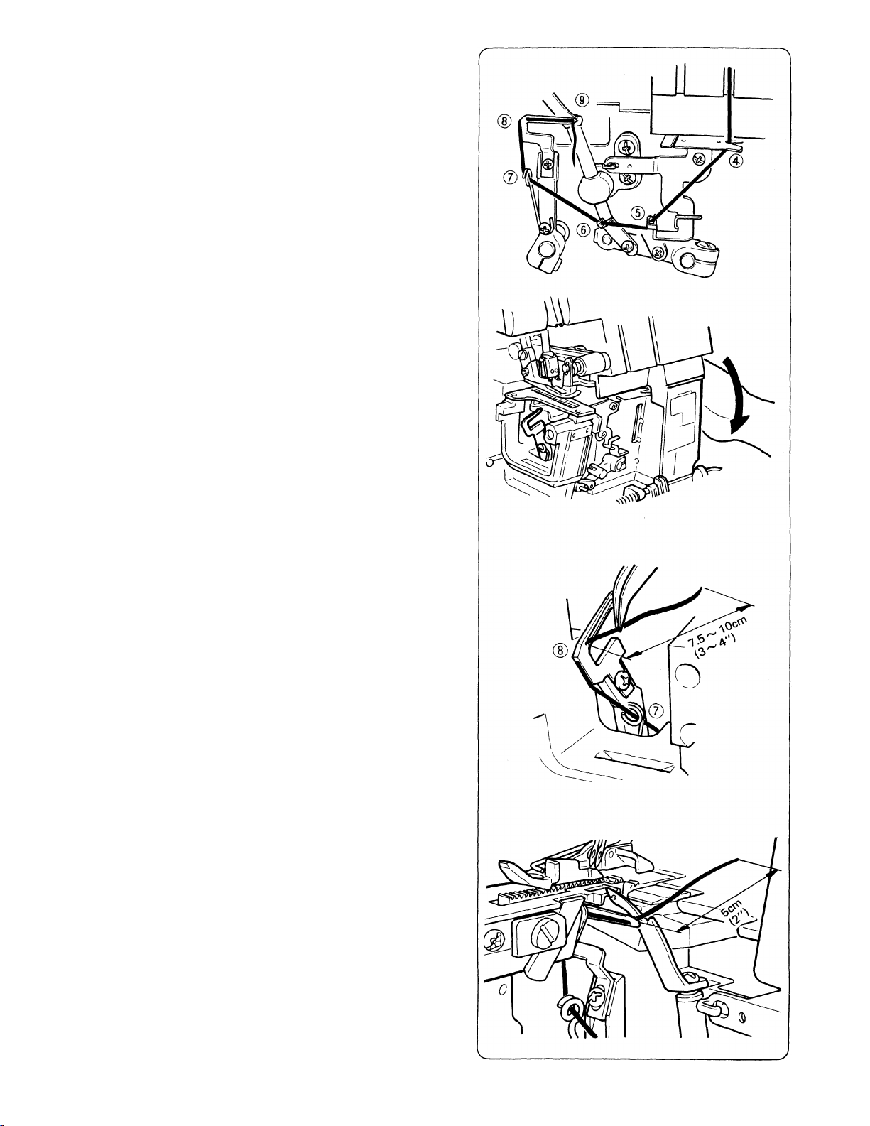
* Thread the looper area of the machine following
the yellow color coded thread guides 0'^®.
* Remove the cylinder cover (page 9) to expose the
lower looper for threading.
* Turn the hand wheel toward you until the lower
looper is at the far left.
* Pull 7.5 10 cm (3 ^ 4 inches) of thread through
thread guide (J).
* Insert the thread through the left end of the lower
looper. 0
* Drop the thread.
Note: Use the tweezers that are in the accessory set
to aid in threading the looper.
* Turn the hand wheel toward you until the lower
looper is at the far right.
Pick up the thread and pass it through the hole in
the end of the looper ® .
* The thread should be positioned in the groove of
the lower looper.
* Pull about 5 cm (2 inches) of thread through the
looper and place it over the top of the upper
looper and to the back of the throat plate.
13
Loading...