


Installation manual
Simrad transducers
Installation principles and guidelines
www.SIMRAD.com
M A X I M I Z I N G Y O U R P E R F O R M A N C E A T S E A
Echo sounder transducers
Installation manual
This document provides a generic description of echo sounder transducer installation. The information must be regarded as general guidelines and recommendations only. The installation shipyard must design and manufacture installation hardware to fit each individual transducer and vessel.
851-160164/H September 2006

Document history
Document number: 851-160164 / ISBN-10: 82-8066-036-4 / ISBN-13: 978-82-8066-036-7
Converted to XML format. Chapters listing all Simrad transducers and their termination to the General Purpose Rev.H September 2006 Transceiver (GPT) are added. Several minor changes to
other descriptions and illustrations. Interactive version on the document (CHM format) introduced.
Copyright
©2006 Simrad Horten AS
The information contained in this document remains the sole property of Simrad Horten AS. No part of this document may be copied or reproduced in any form or by any means, and the information contained within it is not to be communicated to a third party, without the prior written consent of Simrad Horten AS.
Disclaimer
Simrad Horten AS endeavours to ensure that all information in this document is correct and fairly stated, but does not accept liability for any errors or omissions. The document can be changed without prior notice.
Warning
The equipment to which this manual applies must only be used for the purpose for which it was designed. Improper use or maintenance may cause damage to the equipment and/or injury to personnel. The user must be familiar with the contents of the appropriate manuals before attempting to operate or work on the equipment.
Simrad disclaims any responsibility for damage or injury caused by improper installation, use or maintenance of the equipment.
Support
If you require maintenance on your Simrad equipment, contact your local dealer. You can also contact Simrad using the following e-mail address:
e-mail: contact@simrad.com
Simrad Horten AS
Strandpromenaden 50 |
Telephone: +47 33 03 40 00 |
|
P.O.Box 111 |
Telefax: +47 33 04 29 87 |
|
N-3191 Horten, |
www.simrad.com |
|
|
||
Norway |
simrad.sales@simrad.com |
|

Installation manual
Table of contents |
|
INTRODUCTION ................................................................ |
5 |
TRANSDUCER LOCATION .................................................. |
6 |
Go deep..................................................................................................................... |
6 |
Vessel heave ............................................................................................................. |
6 |
Noise from protruding objects on the hull................................................................ |
6 |
Boundary water layer ............................................................................................... |
7 |
Propeller noise.......................................................................................................... |
7 |
Inclination of the transducer face ............................................................................. |
8 |
Summary and general recommendation ................................................................... |
8 |
WAYS OF MOUNTING THE TRANSDUCER ......................... |
10 |
External mounting .................................................................................................. |
11 |
Transducer blister ................................................................................................... |
16 |
Box keel.................................................................................................................. |
22 |
Flush mounting in a steel tank................................................................................ |
24 |
Acoustic window.................................................................................................... |
26 |
Inside the hull ......................................................................................................... |
28 |
Drop keel ................................................................................................................ |
30 |
Retractable transducer ............................................................................................ |
31 |
CABLE GLANDS ............................................................... |
32 |
Order numbers........................................................................................................ |
32 |
Cable gland for steel hulls ...................................................................................... |
33 |
Cable gland for wood or GRP hulls ....................................................................... |
34 |
Cable glands for small hulls ................................................................................... |
35 |
Cable splicing ......................................................................................................... |
36 |
STEEL CONDUIT .............................................................. |
37 |
HANDLING AND MAINTENANCE ...................................... |
38 |
Approved anti-fouling paints.................................................................................. |
39 |
SIMRAD TRANSDUCERS .................................................. |
40 |
All 12 kHz transducers ........................................................................................... |
41 |
All 18 kHz transducers ........................................................................................... |
41 |
All 27 kHz transducers ........................................................................................... |
41 |
All 38 kHz transducers ........................................................................................... |
42 |
All 50 kHz transducers ........................................................................................... |
44 |
All 70 khz transducers............................................................................................ |
45 |
All 120 khz transducers.......................................................................................... |
46 |
All 200 kHz transducers ......................................................................................... |
47 |
851-160164/H |
3 |

Simrad Echo sounder transducers
All 710 kHz transducers ......................................................................................... |
49 |
GPT TRANSDUCER TERMINATIONS ................................. |
51 |
Single beam, normal power transducer .................................................................. |
52 |
Single beam, high power transducer ...................................................................... |
53 |
Dual beam (wide or narrow) transducer................................................................. |
54 |
Split beam transducer ............................................................................................. |
55 |
Split beam transducer to single beam transceiver .................................................. |
56 |
Single beam transducer to split beam transceiver .................................................. |
57 |
Dual frequency, single beam transducer................................................................. |
58 |
Sidescan transducer ................................................................................................ |
59 |
Deep water, split beam transducer.......................................................................... |
60 |
ES38–10 transducer................................................................................................ |
61 |
12-16/60 transducer................................................................................................ |
62 |
50/200 Combi C transducer.................................................................................... |
63 |
38/200 Combi C transducer.................................................................................... |
64 |
4 |
851-160164/H |

Introduction
INTRODUCTION
The purpose of this installation manual is to provide generic descriptions and illustrations allowing the reader to understand the basic principles for echo sounder transducer installation.
Note
The information in this document must be regarded as general guidelines and recommendations only. The installation shipyard must design and manufacture installation hardware to fit each individual transducer and vessel.
Whenever required, the installation shipyard must also have the installation approved by the applicable maritime authorities.
For detailed information about the transducer to be installed, refer to the documentation provided with the transducer. Drawings and descriptions can also be obtained from http://www.simrad.com.
851-160164/H |
5 |

Simrad Echo sounder transducers
TRANSDUCER LOCATION
A single answer to the question where to locate the transducer cannot be given. It depends very much on the vessel’s construction. However, there are some important guide lines.
Go deep
The upper water layers of the sea contain a myriad of small air bubbles created by the breaking waves. In heavy seas the uppermost 5 to 10 metres may be air-filled, with the highest concentrations near the surface. Air bubbles absorb and reflect the sound energy, and may in worst cases block the sound transmission totally. Therefore, mount the transducer at a deep position on the hull.
Consider the situation when the vessel is unloaded, and when it is pitching in heavy seas.
WARNING
The transducer must never be lifted free of the water surface.
Not only will the sound transmission be blocked, but the transducer may be damaged by slamming against the sea surface.
Another reason to go deep is cavitation in front of high power transducers. Cavitation is the formation of small bubbles in the water due to the resulting local pressure becoming negative during parts of the acoustic pressure cycles. The cavitation threshold increases with the hydrostatic pressure.
Vessel heave
Heave is the up and down movement of the vessel. It disturbs the echo traces in the echogram, so that a flat bottom is displayed as a wave. A transducer location in the middle of the vessel minimises the influence of vessel roll and pitch.
Noise from protruding objects on the hull
Objects protruding from the hull, such as zinc anodes, sonar transducers or even the vessel’s keel, generate turbulence and flow noise. Also holes and pipe outlets are noise sources. They may act as resonant cavities amplifying the flow noise at certain frequencies. Do not place an echo sounder transducer in the vicinity of such objects, and especially not close behind them.
For the same reason, it is very important that the hull area around the transducer face is as smooth and level as possible. Even traces of sealing compound, sharp edges, protruding bolts or bolt holes without filling compound will create noise.
6 |
851-160164/H |
Transducer location
Boundary water layer
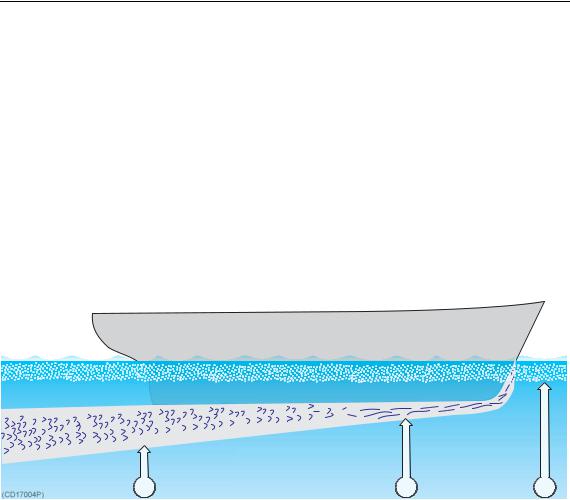
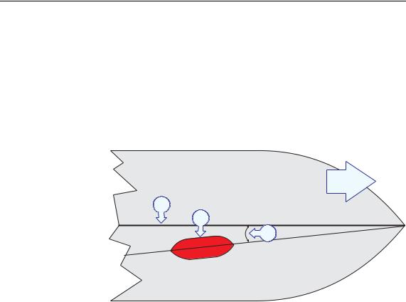
When the vessel forces its way through the sea, the friction between the hull and the water creates a boundary layer. The thickness of the boundary layer depends upon vessel speed and the roughness of the hull. Objects protruding from the hull, and dents in the hull, disturb the flow and increase the thickness of the boundary layer. The flow in this boundary layer may be laminar or turbulent. A laminar flow is a nicely ordered, parallel movement of the water. A turbulent flow has a disorderly pattern, full of eddies. The boundary layer increases in thickness when the flow goes from laminar to turbulent. The figure below illustrates the boundary layer of a vessel moving through the water.
A B C
Boundary water layers:
(A)= Turbulent flow
(B)= Laminar flow
(C)= Air bubbles in the water
Furthermore, air bubbles in the sea water are pressed down below the hull and mixed into the boundary layer. The boundary layer is thin underneath the forward part of the vessel, and increases in thickness as it moves towards aft. If the sides of the hull are steep, some of the air bubbles in the boundary layer may escape to the sea surface along the vessel sides. It is our experience that a wide and flat bottom, with a rising angle less than around 13 degrees, is prone to giving air problems for the transducer. In any case a transducer location in the forward part of the hull is preferred in order to minimise the influence of the boundary layer.
Propeller noise
The propulsion propeller is the dominant noise source on most fishing vessels, research vessels, merchant vessels and pleasure crafts. The noise is transmitted through the sea water. For this reason, the transducer should be placed far away from the propeller, which means on the fore part of the hull. Positions
851-160164/H |
7 |

Simrad Echo sounder transducers
outside the direct line of sight from the propeller are favourable. On small vessels with short distances it is advised to mount the transducer on that side of the keel where the propeller blades move upwards, because the propeller cavitation is strongest on the other side. The cavitation starts most easily when the water flows in the same direction as the propeller blade, and that is to some degree the case at that side of the keel where the propeller blades move downwards.
Bow thruster propellers are extremely noisy. When in operation, the noise and cavitation bubbles make the echo sounder useless, almost no matter where the transducer is installed. And when not in operation, the tunnel creates turbulence, and if the vessel is pitching, the tunnel may be filled with air or aerated water in the upper position and release this in the lower position. Therefore, an echo sounder transducer should be placed well away from the bow thruster.
Inclination of the transducer face
Ideally, the transducer face should be mounted in parallel with the sea surface when the vessel is in normal trim, as this will provide the most accurate echo information. However, it is also very important that the water flow over the transducer face is laminar.
In order to ensure laminar flow, the transducer face may be tilted slightly upwards in relation to the water flow. This allows the flowing water to meet the face directly, and assures laminar flow. The inclination angle must however be determined carefully. The angle must be small on transducers with narrow beam angles. As a rule of thumb, mount transducers with beam angles smaller than seven degrees with minimum inclination angle. The smaller beam angle your transducer has, the smaller the inclination angle can be.
Ensure that you do not mount the transducer with a negative inclination angle. This may cause turbulence under the transducer face, and reduced echo sounder performance.
Summary and general recommendation
Some of the above guide lines are conflicting, and each case has to be treated individually in order to find the best compromise. Generally the propeller noise is the dominant factor, and a recommended transducer location is in the fore part of the hull, with maximum distance from the bow equal to one third of the total length of the hull at the water line.
8 |
851-160164/H |
Transducer location
A B
(CD017004Q) |
M |
|
L |
||
|
General recommendation for transducer location:
(A)= Transducer
(B)= Inclination angle
(L)= Hull length at water line
(M)= Maximum 1/3 of the hull length at water line (L)
If the vessel hull has a bulbous bow, this may well be a good transducer location, but also here must be taken into consideration the flow pattern of the aerated water. Often the foremost part
of the bulb is preferable.
(CD17004C)
A B
Recommended location of the transducer on a bulbous hull:
(A)= Thruster
(B)= Transducer location
851-160164/H |
9 |

Simrad Echo sounder transducers
WAYS OF MOUNTING THE TRANSDUCER
There are many different ways to mount the transducer.
Topics
External mounting on page 11
Transducer blister on page 16
Box keel on page 22
Flush mounting in a steel tank on page 24
Acoustic window on page 26
Inside the hull on page 28
Drop keel on page 30
Retractable transducer on page 31
10 |
851-160164/H |

Ways of mounting the transducer
External mounting
Certain transducers have a streamlined housing, and these are designed for installation outside the hull.
These transducers are mainly used on smaller vessels. A location approximately 0.5 m aside from the keel may be adequate for the passage of water between the keel and the transducer. The figures illustrate external mounting of transducers on steel hulls and on wood or polyester hulls respectively.
Smooth surface
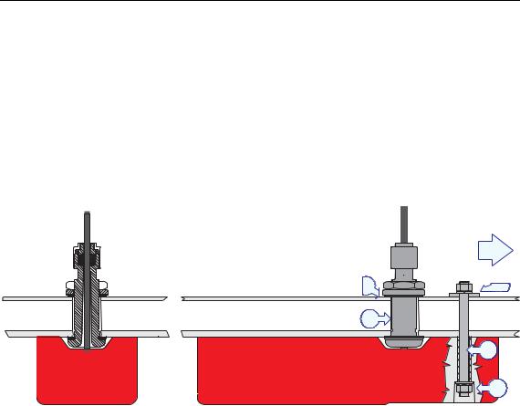
Ensure that the surface of the transducer face, the hull plating and putty around the transducer is as even and smooth as possible. Obstructions on these surfaces will create problems with turbulant flow.
Mounting screws must not be extruding from the transducer, and the space around the screws must be filled with a compound (C) and/or a locking ring.
851-160164/H |
11 |
Simrad Echo sounder transducers
(CD017007A)
Steel hull
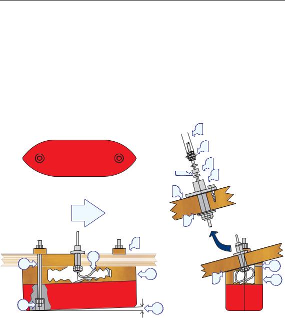
A fairing (A), made by the shipyard, is placed between the transducer and the hull. It is required in order to adapt for the deadrise angle of the hull, and it will also house a cable service loop (B). The fairing can be made of wood or steel, and should have the same outline dimensions as the transducer. Remember to create an air outlet (E) on the fairing, and to fill the bolt holes with a filling compound to ensure a smooth transducer surface.
|
|
|
1 |
|
|
|
2 |
|
|
|
3 |
|
|
4 |
5 |
|
|
|
|
|
F |
|
|
|
B |
|
E |
|
|
|
|
I |
A |
|
A |
|
|
||
|
|
|
C D
D
(A)= Fairing
(B)= Cable service loop
(C)= Filling compound
(D)= Inclination angle
(E)= Air outlet
(F)= Forward
(I) = Threaded rod with nuts and washers, or bolt
(1)= Steel conduit
(2)= Stuffing tube
(3)= Washer
(4)= Rubber gasket
(5)= Packing nipple
12 |
851-160164/H |
I
(CD17007B)
C
Ways of mounting the transducer
Wood or polyester hull
A fairing (A), made by the shipyard, is placed between the transducer and the hull. It is required in order to adapt for the deadrise angle of the hull, and will also house a cable service loop (B). The fairing is made from wood, polyester or steel, and should have the same outline dimensions as the transducer. Use tarred felt (H) between the fairing and the hull. Remember to create an air outlet (E) on the fairing, and to fill the bolt holes with a filling compound to ensure a smooth transducer surface.
|
|
1 |
|
|
|
5 |
|
|
|
4 |
|
|
3 |
2 |
|
|
|
|
|
|
4 |
|
|
F |
4 |
|
|
|
|
|
|
G |
|
|
|
B |
|
|
|
|
|
|
E |
A |
|
H |
A |
|
|
||
D |
|
|
|
(A) = Fairing |
(1) |
= Steel conduit |
|
(B) = Cable service loop |
(2) |
= Stuffing tube |
|
(C) = Filling compound |
(3) |
= Washer |
|
(D) = Inclination angle |
(4) |
= Rubber gasket |
|
(E) = Air outlet |
(5) |
= Packing nipple |
|
(F)= Forward
(G)= Shim (wood)
(H)= Tarred felt
(I)= Threaded rod with nuts and washers, or bolt
851-160164/H |
13 |
Simrad Echo sounder transducers
(CD017007C)
Hull with flat bottom
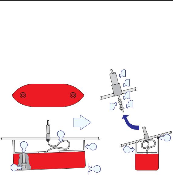
If the vessel’s hull is flat you do not need a fairing. The transducer is then be bolted directly to the hull using two bronze or stainless steel bolts (I) and a cable bushing. Note that the cable bushing must be mounted with proper gaskets (4) under and over the hull, as well as sealing compound (J) around its body. Also, fill the bolt holes with a filling compound to ensure a smooth transducer surface.
F
4 |
3 |
J
I
C
(C) = Filling compound
(F) = Forward
(I) = Threaded rod with nuts and washers, or bolt
(3)= Washer
(4)= Rubber gasket
14 |
851-160164/H |
Ways of mounting the transducer
Toe-in
The primary consideration must be to allow laminar water flow. In most cases this is achieved by placing the transducer (A) parallel with the keel (C). However, if the transducer is located close to the bow, the front of the transducer may have a few degrees (5 to 8°) toe-in towards the bow. If you have a planing hull, the toe-in must be 0°.
F
C
A
B
(CD017007D)
(A)= Transducer
(B)= 5 to 8° on deplacement hulls, 0° on planing hulls
(C)= Keel
(F) = Forward
851-160164/H |
15 |

Simrad Echo sounder transducers
Transducer blister
With a transducer with circular housing, one recommended installation method is by using a blister. The transducer blister must be designed and manufactured by the installation shipyard to fit the vessel’s size and hull shape.
Mounting and clamping rings
Circular transducers may be provided with mounting and clamping rings, or with drawings to allow for local production of these. The mounting ring is welded to the hole in the transducer blister, while the clamping ring fits around the edge of the transducer body. Bolts through the clamping ring into the mounting ring will then secure the transducer between them. Note that several transducers use direction guides to allow correct mounting.
Smooth surface
Mounting screws or bolts must not be extruding from the transducer blister. Ensure that the surface of the transducer face, the blister, the hull plating and putty around the transducer is as even and smooth as possible. Obstructions on these surfaces will create problems with turbulant flow.
Horizontal support bar
Large diameter transducers must be fitted with a horizontal support bar. This bar can be secured to the mounting ring using threaded rods.
16 |
851-160164/H |
Ways of mounting the transducer
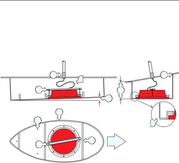
Example: Large transducer
The illustration below shows a typical transducer blister designed for a large transducer. Note that due to the physical size of
the transducer, a U-shaped support bar (E) is used to support the transducer. The purpose of this support is to prevent the transducer from being pushed up into the blister in heavy seas.
H |
K |
G |
|
E |
I |
|
D |
(CD017010A) |
|
A |
|
C |
J |
|
|
B |
F |
E |
|
(A) = Streamlined blister |
(G) = Cable service loop |
(B) = Stiffening rib |
(H) = Stuffing tube |
(C) = Drainage holes |
(I) = Minimum 400 mm |
(D) = Inclination angle |
(J) = Rounded corners |
(E) = U-shaped support bar |
(K) = Air outlet |
(F) = Forward |
|
851-160164/H |
17 |
Simrad Echo sounder transducers
Example: Small transducer
The illustration below shows a typical transducer blister designed for a small transducer. The same blister design principles as for a large transducer apply.
E E
A
B
(CD017010B) |
F |
|
G
C
D
(A) = Streamlined blister |
(E) = Air outlet |
(B) = Mounting ring |
(F) = Forward |
(C) = Clamping ring |
(G) = Transducer cable |
(D) = Guide |
|
Note that the transducer cable must be provided with a cable loop inside the blister. Observe the vertical forward edge of the blister. This will guide the water to each side of the blister.
18 |
851-160164/H |
Ways of mounting the transducer
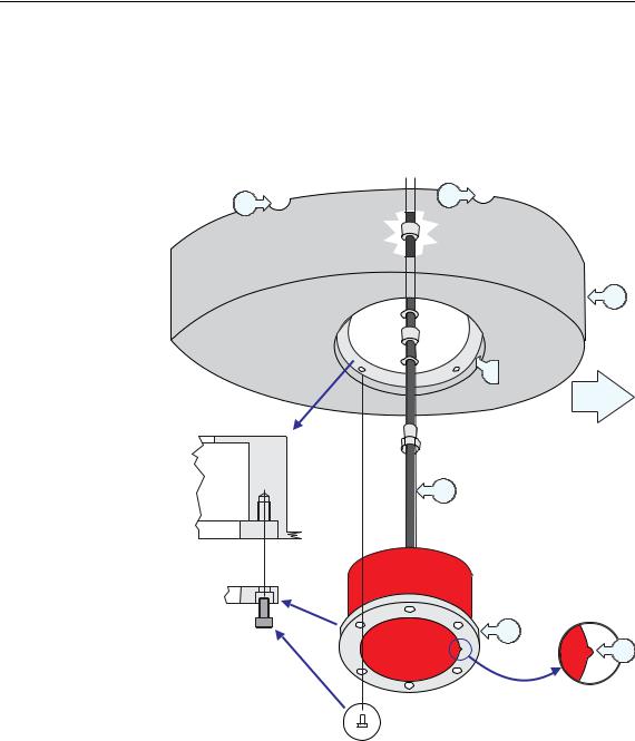
Example: Medium sized transducer without clamping ring
The illustration below shows a transducer blister designed for a medium sized transducers. The same blister design principles apply. Note that the transducer is mounted without a clamping ring, which makes it necessary to use a different mounting ring design.
E
E
A
F
B
I
D
G
H
C
(CD017010E)
(A) = Streamlined blister |
(E) = Air outlet |
(B) = Mounting ring |
(F) = Forward |
(C) = Bolt |
(G) = Transducer cable |
(D) = Self-locking threads |
(H) = Transducer |
Note that the transducer cable must be provided with a cable loop inside the blister. Observe the vertical forward edge of the blister. This will guide the water to each side of the blister.
851-160164/H |
19 |
 Loading...