


FS 70 OPERATOR MANUAL
974-24007001
Issue 3.0 |
January 2009 |
FS 70 Operators Manual |
974-24007001/3.0 |
List of Contents |
Page 1 |
KONGSBERG MESOTECH LTD
Customer Products Warranty Policy
Effective January 1, 2009
Kongsberg Mesotech Ltd. Warrants each new product (equipment) to be free of defects caused by faulty materials or poor workmanship for a period of twenty-four (24) months for underwater and surface equipment from date of installation by an authorized Kongsberg Group Company, Simrad Distributor, Dealer or Agency. The warranty does not apply to defects caused by force majeure events or misuse including water damage to the surface equipment, improper maintenance and installation or including excessive wear and tear for which Kongsberg Mesotech Ltd. is not responsible.
Underwater Equipment:
•Warranty for Underwater Equipment that is hull mounted, such as those mentioned below, will be assessed on a case-by-case basis but shall generally not be covered by the warranty:
•Hull Units, Sonar Dome Assemblies and Echo Sounder Transducers
•Transducer Units, Speed, Temperature and Depth Sensors
Note: Additional expenses connected with replacement of transducers, such as drydocking and diving, are not covered by this warranty.
Warranty on Parts or Equipment Replacement:
•It is at the sole discretion of Kongsberg Mesotech Ltd. to either repair or replace any unit/part that fails within the limits of the Warranty Policy.
•The Warranty Policy is only valid on new equipment
•Replacement of parts, components, and/or PCB Boards during a warranty repair does not extend the original warranty period.
Kongsberg Mesotech Ltd.
Port Coquitlam, BC - Canada
974-24007001/3.0 |
FS 70 Operators Manual |
Page 2 |
List of Contents |
Consumable Materials:
•Consumable materials, such as lamps, fuses, O-rings, gaskets and batteries, will not be replaced free of charge.
Warranty Service:
•Warranty service is available worldwide through authorized Kongsberg Group Companies, Simrad Distributors, Dealers or Agencies. When requesting warranty service, you must supply the following information:
1.Proof of purchase.
2.Equipment part number and serial number.
3.Fault description and all relevant vessel information.
•Labour cost for the repair or replacement of any products/equipment and/or module/parts is the responsibility of the servicing agent or dealer.
•All customs duties, brokerage charges ocal taxes, overtime, expenses for meals, tools, launch services, ferries, lodgings, normal adjustments and routine maintenance are not covered by this warranty policy.
DISCLAIMER
•Maximum liability shall not, in any case, exceed the contract price of the products claimed to be defective.
•Consequential damages including, but not limited to, any loss of profit, property damage or personal injury, are not covered by the warranty policy.
•This equipment is not certified or approved for navigation and/or safe-navigation practices, and is not to be used for navigation purposes under any circumstances.
Kongsberg Mesotech Ltd.
Port Coquitlam, BC - Canada
FS 70 Operators Manual |
974-24007001/3.0 |
List of Contents |
Page 3 |
LIST OF CONTENTS
Part 1 |
...................................................................................... System Familiarization |
Part 2 |
.......................................................................................... Theory of Operation |
Part 3................................................................................... |
FS 70 System Operation |
Part 4..................................................... |
FS 70 Installation, System Set-Up and Test |
Part 5.................................................................... |
Troubleshooting and Maintenance |
Part 6................................................................................... |
Drawings & Attachments |
Kongsberg Mesotech Ltd.
Port Coquitlam, BC - Canada
974-24007001/3.0 |
FS 70 Operators Manual |
Page 4 |
List of Contents |
Kongsberg Mesotech Ltd.
Port Coquitlam, BC - Canada
FS 70 Operators Manual |
974-24007001/3.0 |
List of Contents |
Page 5 |
MODIFICATION RECORD
FS 70 OPERATORS MANUAL
974-24007001
Issue: 3.0
January 2009
Issue No. |
Date |
Initial |
Comments |
1.0 |
01.06 |
L.F |
First release |
|
|
|
|
2.0 |
01.07 |
L.F |
Second release |
______3.0_________01.09________ L.F________Third release_______________
To assist us in making improvements to the product and documentation, Kongsberg Mesotech welcomes comments and constructive criticisms.
Please send all such comments, in writing or by E-mail, to:
Kongsberg Mesotech Ltd.
Documentation Department
1598 Kebet Way
Port Coquitlam, BC V3C 5M5
Canada
E-Mail: km.sales.vancouver@kongsberg.com
Kongsberg Mesotech Ltd.
Port Coquitlam, BC - Canada
974-24007001/3.0 |
FS 70 Operators Manual |
Page 6 |
List of Contents |
Kongsberg Mesotech Ltd.
Port Coquitlam, BC - Canada
FS 70 Operators Manual |
974-24007001/3.0 |
|
System Familiarization |
Page 1.1 |
|
|
PART 1 |
|
|
SYSTEM FAMILIARIZATION |
|
1. SYSTEM FAMILIARIZATION........................................................................... |
1.3 |
|
1.1 OVERVIEW ............................................................................................... |
1.3 |
|
1.1.1 |
Equipment Configuration ....................................................................... |
1.3 |
1.1.2 |
System Configuration............................................................................. |
1.4 |
1.1.3 |
Display Monitor ...................................................................................... |
1.4 |
1.1.4 |
Processor Unit ....................................................................................... |
1.4 |
1.1.5 Power /TTM Interface Module................................................................ |
1.5 |
|
1.1.6 |
Deployment Housing Unit ...................................................................... |
1.5 |
1.1.7 |
Jointing Tool........................................................................................... |
1.6 |
1.1.8 |
Catch Sensors ....................................................................................... |
1.6 |
1.1.9 |
PI Sensors Option.................................................................................. |
1.6 |
1.1.10 Depth & Temperature NMEA Output.................................................. |
1.6 |
|
1.1.11 Trawl Cable, Winch and Block ........................................................... |
1.6 |
|
1.1.1219” Rack Cabinet 9U, ......................................................................... 1.7
Kongsberg Mesotech Ltd.
Port Coquitlam, BC - Canada
974-24007001/3.0 |
FS 70 Operators Manual |
Page 1.2 |
System Familiarization |
Kongsberg Mesotech Ltd.
Port Coquitlam, BC - Canada
FS 70 Operators Manual |
974-24007001/3.0 |
System Familiarization |
Page 1.3 |
1. SYSTEM FAMILIARIZATION
1.1 OVERVIEW
The SIMRAD FS 70 Series is a third wire trawl monitoring system for pelagic and bottom fishing trawlers. The system provides real time images from the trawl sonar head and data from the sensors to the bridge, thus maximizing the quality of the catch and reducing sea time.
The FS 70 vertical trawl sonar allows the operator to see the complete net opening and operation by displaying individual fish targets in the vertical plane, the fish school location, bottom/net location and net geometry. In addition to the vertical monitoring, the FS 70 also allows the operator to measure the spread of the trawl door, view and skim banks to avoid reefs and locate boulders on the ocean floor that may damage the trawl net.
The 200kHz Echo Sounder capability ensures maximum control of the foot rope during the tow. The active motion sensor for pitch and roll comes as a standard feature.
The addition of the trawl system’s sensor module will allow the operator to monitor trawl depth, water temperature and receive information from up to 6 catch receivers indicating when the cod end fills up with fish.
The FS Trawl Sonar Series is a modular system. It is operated with ease through direct access Mouse and Keyboard operated menus. The major benefit of the third wire trawl sonar system is that it prevents the loss of communication with the trawl as the vessel is changing course.
1.1.1 Equipment Configuration
A complete Trawl Monitoring System consists of:
•Simrad LCD or VGA display monitor. (optional)
•FS 70 Processing Server Industrial Unit.
•FS PWR/TTM Interface Module, 19” Rack Mounted 3U
•FS 70, Vertical Sonar Head 120kHz, or 330kHz, C/W 200kHz Sounder
•40kHz or 70kHz Catch Sensors
•Integrated Pitch and Roll Motion Sensor
•FS 70 Deployment Housing and Installation materials
•Industrial 9U, 19” Rack Cabinet, c/w with fans and glass door, (optional)
•Industrial UPS 19” Rack mounted 2U, 120Vac or 230Vac, (optional)
Refer to Part 6 “Attachment” for full Configuration Overview
Kongsberg Mesotech Ltd.
Port Coquitlam, BC - Canada
974-24007001/3.0 |
FS 70 Operators Manual |
Page 1.4 |
System Familiarization |
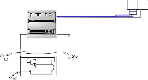
1.1.2 System Configuration
FS 70 TRAWL Monitoring
Integrated System Configuration
|
Rack Integrated System Cabinet |
LCD |
LCD |
|
Monitor |
Monitor |
|
|
9 U |
||
|
|
|
|
3 U |
30m.VGA Extender Cable c/w K & M, |
KB & M |
|
SIMRAD Power/TTM |
|
|
|
|
|
|
|
1 U |
30m.VGA Extender Cable |
|
|
|
120 or 230 AC Power |
||
|
|
||
3 U |
|
|
Input |
|
|
|
|
2 U |
|
System Standard Equipments |
|
|
|
|
|
|
|
|
|
120 or 230 AC Power |
3 |
U, 19" Rack Power/TTM c/w Front Test Cable Connection |
|
|
|
|
|
|
|
|
|
1 |
U, 19" Rack Industrial Processing Unit |
||
|
|
|
|
|
|
|
|||||
|
|
|
|
|
|
|
|
|
Input |
3 |
U, Expansion Space for Future Development |
|
|
|
|
|
|
|
|
|
|
||
Door Spread |
|
|
|
|
|
|
2 U, 19" Rack APC, 1500 UPS |
||||
|
FS 70 Head Trawl unit |
Catch Hydrophone |
|
Rack Cabinet Description |
|||||||
Hydrophone |
|
|
|
|
|||||||
|
|
|
|
|
|
|
|
|
|
|
|
|
|
|
|
|
|
|
|
|
|
|
|
|
|
|
|
|
|
|
|
|
|
|
|
1
2
PI Door Sensors
1
3
2
or |
2 |
|
4 |
|
1 |
|
3 |
TS15 S Head |
PI Catch Sensors |
|
40kHz or 70kHz |
FS 3300 Sensor |
|
Cabinet, W 23.6", (600mm), D 23.6", (600mm) H 19.8", (502mm) Dual 6" Ventilation Fan & Bracket
30m VGA Video Extender Cable c/w KB & Mouse
30m VGA Video extender Cable for Dual Monitor Slide Rails
Glass Door
All Mounting Hardware Included
Refer to your price list for additional information
4
Catch Sensors
70kHz Only
Kongsberg Mesotech Ltd.
Port Coquitlam, BC - Canada
1.1.3 Display Monitor
The display monitor for the FS 70 can be a VGA ruggedized LCD monitor but any commercially available VGA monitor may be used. This is in order to have the full benefit of high resolution provided by the video Multi-Display adapter available with the FS Processors.
1.1.4 Processor Unit
The FS 70 19” Rack mounted Industrial Processing unit is the control unit for the system. The installed FS 70 system software provides a mechanism for the sonar head detection, setup and operation. It is operated through the Main Control panel to enable the Sonar selection, tilt, range, gain, cursor, and by moving the mouse pointer over the toolbar will allow the operator to perform certain operations with a simple Right or Left mouse click.
Kongsberg Mesotech Ltd.
Port Coquitlam, BC - Canada
FS 70 Operators Manual |
974-24007001/3.0 |
System Familiarization |
Page 1.5 |
The sector heading and width are also controlled by a single mouse click used to set the center of the area to be scanned and the width of the sector scan (up to 360°) in the polar mode.
The rear panel of the Processing unit contains the connectors for AC power, Dual Monitor port, one Serial port and several USB ports, Keyboard, Mouse, Printer, and Network port. The Network port can be used to connect the remote workstation. Note: A security key (or “dongle”) must be attached to a USB port to enable full operation of the system.
1.1.5 Power /TTM Interface Module
The FS 19” Rack mounted Power/TTM interface Module unit provides the high voltage required by the trawl sonar. The DC output voltage is combined with the telemetry signals and supplied to the trawl sonar.
The power voltage supplied to the sonar head and current are monitored by voltage and current meters. A selector switch located below the voltage meter can be used to select the output voltage of the power supply required for the appropriate system configuration. Also, a separate on/off switch is located in the front panel. Note: The main on/off switch and fuse are located on the rear panel of the TTM Module.
The Power/TTM Interface provides translation between the Processing Unit Serial or USB port and the sonar telemetry communication protocol.
A Test Cable connector and selection switch between the trawl cable and Test cable are provided in the front panel, eliminating having to disconnect the 3rd wire cable from the rear of the TTM.
1.1.6 Deployment Housing Unit
The trawl deployment housing unit is made from polyurethane and designed for the harshest of environments yet it is easy to handle. The FS 70 trawl unit sits within the deployment housing unit and contains the vertical sonar head, catch hydrophone receiver, the optional forward hydrophone, the echo sounder 200kHz transducer and depth and temperature sensors. The mounting kit supplied contains the strain relief cable gland and other hardware used to attach the trawl cable to the trawl headrope.
The trawl cable is connected to the trawl sonar by a watertight connector and a locking sleeve. Commands are sent down the cable from the processors to operate the sonar. The sonar image and sensor data are sent up the cable to the processor and displayed on the appropriate monitor.
Kongsberg Mesotech Ltd.
Port Coquitlam, BC - Canada
974-24007001/3.0 |
FS 70 Operators Manual |
Page 1.6 |
System Familiarization |
1.1.7 Jointing Tool
Jointing tools and materials are required for splicing the trawl cable and attaching the trawl “2 pin pigtail” connector to the trawl sonar. We recommend using 3M 72-N1 jointing tool kits that can be purchase locally and especially designed for coaxial cable with a breaking point of 1500kg. The jointing kit will allow you to make 1 cable joint.
Note: Proper joining and crimping sleeve will be required based on the type of 3rd wire you are using.
1.1.8 Catch Sensors
The catch sensor “eggs” are wireless sensors mounted on the cod-end of the trawl net to detect the stretch of the net as it fills up with the catch. When sufficient stretch of the net occurs, the catch sensor sends an acoustic signal to the trawl sonar through the catch receiver.
This information is then sent to the processor and displayed on the monitor.
The sensors are of a rugged construction in order to withstand the strain from winches and the power block. The operator can use up to six sensors (with the 40kHz system) simultaneously. The catch sensors are equipped with rechargeable batteries.
1.1.9 PI Sensors Option
The FS 70 provides full integration with the PI System, Door Spread, Bottom Contact, Rip Sensor and Cod End Depth Sensor available from Simrad Horten AS.
1.1.10 Depth & Temperature NMEA Output
The FS 70 processing Unit can be configured to output NMEA 183 data information. The integrated sensor module is included in the sonar head. The depth and temperature outputs are transmitted to the processor and displayed on the monitor. When interfaced to other Simrad echo sounders, the headrope depth information appears on the sounder showing the location of the trawl in relation to the fish or bottom returns.
1.1.11 Trawl Cable, Winch and Block
The trawl cable is chosen for maximum mechanical strength, durability and minimum attenuation of the signals. Cables in common use are coaxial with breaking points of 1500kg and 6000kg.
Kongsberg Mesotech Ltd.
Port Coquitlam, BC - Canada
FS 70 Operators Manual |
974-24007001/3.0 |
System Familiarization |
Page 1.7 |
Cable winches are delivered in different types and with different capacities; lowpressure hydraulic, high-pressure hydraulic and electrically driven. Choice of winch is dependent on prevailing conditions; type and length of cable and available source of power. Most types operate automatically - the cable is pulled out, kept tight during towing, and hauled in together with the trawl. Control of the winch is done remotely from the bridge.
Any commercially available pulley block may be used to properly align the cable onto the winch. A snatch block has the advantage that it may be installed without having to thread the cable through it. A unit with two movable steering arms (one on each side of the pulley) is recommended to prevent the cable from coming off the pulley and causing damage to the cable.
1.1.12 19” Rack Cabinet - 9U,
The Industrial Ventilated Rack Cabinet with a rugged black powder paint finish is an ergonomic design with ventilated slots front and side. The pre-punched top allows the installation of 2 fans. Cable accesses are available from the top or bottom.
The cabinet includes two pair of mounting rails, smoked glass door with full 180 degrees opening for easy access to the rack mounted equipment.
The overall dimensions are 19.8” (502mm) height, 23.6” (600mm) width, 24.0” (600mm) depth.
Kongsberg Mesotech Ltd.
Port Coquitlam, BC - Canada
974-24007001/3.0 |
FS 70 Operators Manual |
Page 1.8 |
System Familiarization |
Kongsberg Mesotech Ltd.
Port Coquitlam, BC - Canada
FS 70 Operators Manual |
974-24007001/3.0 |
Theory of Operation |
Page 2.1 |
PART 2
THEORY OF OPERATION
2. THEORY OF OPERATION............................................................................... |
2.3 |
||
2.1 INTRODUCTION ....................................................................................... |
2.3 |
||
2.1.1 |
Basic Principles...................................................................................... |
2.3 |
|
2.1.2 |
Determining Target Position .................................................................. |
2.3 |
|
2.1.3 |
Forming an Image.................................................................................. |
2.3 |
|
2.1.4 |
Key Feature Setting ............................................................................... |
2.4 |
|
2.1.4.1 |
AGC ................................................................................................ |
2.4 |
|
2.1.4.2 |
RCG................................................................................................ |
2.4 |
|
2.1.4.3 RX Gain Response and Type ......................................................... |
2.5 |
||
2.1.4.4 |
Pulse Length Control ...................................................................... |
2.5 |
|
2.1.4.5 |
Optimize Resolution........................................................................ |
2.5 |
|
2.1.4.6 |
Maximize Range ............................................................................. |
2.5 |
|
2.1.4.7 |
Peak Detection ............................................................................... |
2.6 |
|
Kongsberg Mesotech Ltd.
Port Coquitlam, BC - Canada
974-24007001/3.0 |
FS 70 Operators Manual |
Page 2.2 |
Theory of Operation |
Kongsberg Mesotech Ltd.
Port Coquitlam, BC - Canada
FS 70 Operators Manual |
974-24007001/3.0 |
Theory of Operation |
Page 2.3 |
2.THEORY OF OPERATION
2.1INTRODUCTION
This section explains the theory of operation of the Vertical and Sounder Scanning Trawl Monitoring Sonar System.
2.1.1Basic Principles
•Sound waves travel very efficiently through water.
•A sound pulse can be projected through water in a controlled direction with the sonar transducer.
•An object in the path of the projected sound pulse will reflect some sound pulses back toward the sonar transducer.
•The speed of the sound pulse projected through the water can be predicted for given conditions.
2.1.2Determining Target Position
The trawl scanning sonar processor measures the time from the start of the sound pulse projected through water, to the reception of the sound pulse reflected back to the sonar transducer. The measured time is then converted to distance by using the value of sound speed through water.
Since the sound pulse is projected in a known direction, the bearing of the reflected object is also known. This makes it possible to locate the object with respect to the sonar transducer; the information will be used to plot the position of the reflected target on a video graphic display monitor.
2.1.3Forming an Image
The sound pulse projected will be attenuated as it travels through the water from the transducer to the target and back. Much of this attenuation is a predictable function of the total time or the distance the sound pulse traveled through water. Increasing the receiving gain with time can compensate for this decrease in the signal level. This is done automatically in the sonar with a Time Varying Gain (TVG) circuit.
Kongsberg Mesotech Ltd.
Port Coquitlam, BC - Canada
974-24007001/3.0 |
FS 70 Operators Manual |
Page 2.4 |
Theory of Operation |
After the TVG correction, the absolute levels of the received signals will be determined by the acoustic response of the reflecting target.
The sonar processor system repeatedly measures the TVG corrected target levels by digitizing a sequence of samples after each sound pulse transmission. Each sample is then plotted on the video display at the appropriate position according to its range and bearing. The level of the target strength sample determines the color used to plot each sample.
The process can be repeated with the transducer pointed in different directions, forming an image of a large area of the bottom, (or the trawl net geometry) and displaying it on the video screen.
In simple words, the TVG function controls the gain of the receiver so that a school with a given size and density is presented with approximately the same strength on the display, inside the regulated TVG range.
2.1.4Key Feature Setting
The following paragraph will explain some of the key features of the FS 70 System.
2.1.4.1 AGC
Automatic Gain Control (AGC)
The AGC “Automatic Gain Control” algorithm increases the gain during low acoustic returns and reduces the gain during strong acoustic returns. The speed with which the gain is adjusted is determined by the setting of the “RX Gain Response”
2.1.4.2 RCG
Reverberation Controlled Gain (RCG)
The RCG filter senses the noise level (reverberation, propeller noise, etc.), and adjusts the gain of each of the received beams in order to eliminate noise on the display. The strength of the filter can be selected in the menu. With maximum strength selected, the RCG will effectively reduce the bottom in shallow water, while variation on the bottom will be displayed.
Note that scattered fish can be perceived as reverberation. The RCG filter must be used with care if scattered schools are to be detected.
Kongsberg Mesotech Ltd.
Port Coquitlam, BC - Canada
FS 70 Operators Manual |
974-24007001/3.0 |
Theory of Operation |
Page 2.5 |
2.1.4.3 RX Gain Response and Type
The setting of the “RX Gain Response” determines the response of the filter algorithm as selected by the “RX Gain Type”. For the AGC, this setting determines the speed by which the gain is adjusted. For the RCG, this setting determines the influence of the previous ping average over the current ping. If set to Slow, the overall average is given by the sum of 20% current and 80% of previous average. In Medium this ratio is 50% to 50%, and in Fast the ratio is 80% to 20%.
2.1.4.4 Pulse Length Control
The FS 70 Trawl Sonar Heads are capable of changing the acoustic pulse length that is transmitted. The surface processing unit sets the pulse length based on the operating range of the sonar head. It is generally better to use a longer pulse as the operating range increases. However, the actual value can be optimized to enhance the details in the sonar image (Optimize Resolution) or to increase the target visibility at long distance away from the sonar head (Maximum Range). The system will automatically set the pulse length to match the range, unless manually adjusted by the operator.
2.1.4.5 Optimize Resolution
The pulse length selection can be optimized to enhance the detail of the targets. It has been experimentally determined that the pulse length corresponding to 40% of the sample period can increase the image resolution and details for targets that are generally larger than a few samples. This pulse length increases linearly with increasing operating range.
2.1.4.6 Maximize Range
The pulse length calculation can be optimized to increase the detection range of the sonar head. Generally, the longer the pulse length, the more energy is transmitted into the water which could then travel a longer distance and get reflected from the targets that are further away from the sonar head. It has been determined that the pulse length corresponding to 80% of the sample period can increase the detection distance of the targets without a major drain on the sonar head power supply. This pulse length increases linearly with increasing operating range.
Kongsberg Mesotech Ltd.
Port Coquitlam, BC - Canada
974-24007001/3.0 |
FS 70 Operators Manual |
Page 2.6 |
Theory of Operation |
2.1.4.7 Peak Detection
The Peak Detection feature is described as follows.
The older sonar heads were not capable of changing the acoustic pulse length. They were generally operated at a pulse length of 100 Microseconds. This meant that at a range greater than 50 meters, there would have been a good chance of not detecting small targets. The reason for this is that the combination of small target size, short pulse length and long sample period could result in the acoustic return from the target falling between two samples and therefore not beings seen on the sonar image.
To remedy this, it was decided to take additional samples and select the strongest echo target for the sonar image display. This is generally referred to as Peak Detection because we are detecting the peak value of signal in between two samples. The user can select the number of additional samples that the system takes in order to detect the peak value.
Kongsberg Mesotech Ltd.
Port Coquitlam, BC - Canada
FS 70 Operators Manual |
974-24007001/3.0 |
FS 70 System Operation |
Page 3.1 |
PART 3
`FS 70 SYSTEM OPERATION
3. FS 70 SYSTEM OPERATION .......................................................................... |
3.3 |
||
3.1 |
INTRODUCTION ....................................................................................... |
3.3 |
|
3.2 |
CONTROL PANEL..................................................................................... |
3.4 |
|
3.2.1 Operating Control Panel Page ............................................................... |
3.5 |
||
3.2.2 Display Control Panel Page ................................................................... |
3.6 |
||
3.2.3 Setup Control Panel Page...................................................................... |
3.7 |
||
3.2.4 Users Settings Control Panel Page........................................................ |
3.8 |
||
3.2.5 Sensors Control Panel Page & Setup .................................................... |
3.9 |
||
3.2.6 PI, 40kHz Channel Sensors Setup....................................................... |
3.10 |
||
3.2.7 PI, 40kHz Receiver Sensors Setup...................................................... |
3.11 |
||
3.2.8 PI, 40kHz Sensors Activation Menu..................................................... |
3.12 |
||
3.2.9 PI, 70kHz Sensors Activation Menu..................................................... |
3.13 |
||
3.2.10 |
Advanced Panel Page ...................................................................... |
3.14 |
|
3.2.11 Advanced Operation TVG Mode ...................................................... |
3.14 |
||
3.2.12 |
Display Rec Toolbar ......................................................................... |
3.15 |
|
3.2.13 |
Record Selection .............................................................................. |
3.15 |
|
3.3 |
DISPLAY TOOLS SELECTION ................................................................. |
3.16 |
|
3.4 |
DEPTH AND TEMPERATURE GRAPHS ................................................ |
3.16 |
|
3.5 |
LANGUAGE............................................................................................. |
3.17 |
|
3.6 |
AUDIO SET UP........................................................................................ |
3.17 |
|
3.7 |
ACTIVATING THE SONAR...................................................................... |
3.18 |
|
Kongsberg Mesotech Ltd.
Port Coquitlam, BC - Canada
974-24007001/3.0 |
FS 70 Operators Manual |
Page 3.2 |
FS 70 System Operation |
Kongsberg Mesotech Ltd.
Port Coquitlam, BC - Canada
FS 70 Operators Manual |
974-24007001/3.0 |
FS 70 System Operation |
Page 3.3 |
3.FS 70 SYSTEM OPERATION
3.1INTRODUCTION
The FS 70 Sonar uses a control panel for the most frequently needed adjustments and a software menu system for less frequently needed controls. This chapter describes the menu system and explains the adjustments to the menu settings that may be made to control the sonar operation
The menu system allows adjustments to several system parameters without requiring a dedicated Control Panel for each item. Items that lead to dialog boxes are shown in the “Advance Menu”. All other items are system parameters that may be modified. As you move the pointer over the Control Panel, a simple help message will pop up beside the pointer describing its function. To perform certain operations, just left or right click the mouse over the desired item. Selected items are highlighted.
Kongsberg Mesotech Ltd.
Port Coquitlam, BC - Canada
974-24007001/3.0 |
FS 70 Operators Manual |
Page 3.4 |
FS 70 System Operation |
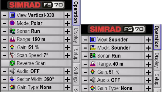
3.2 CONTROL PANEL |
|
The Sonar Control Panel located above is divided into 7 Pages, Page 1 “Operation”, Page 2 “Display”, Page 3 “Setup”, Page 4 “Settings”, Page 5 “Sensors Control”, Page 6 & 9 “Sensors”, Page 4 & 8 “Receiver Setup” and Page 10 “Advanced”. Each page allows you to change the system parameters. To change the value of a system parameter, move the mouse up or down until the desired button is highlighted and click the left mouse button or right mouse button to activate the new setting.
Note: The main control panel can be docked or auto-hidden.
Kongsberg Mesotech Ltd.
Port Coquitlam, BC - Canada
FS 70 Operators Manual |
974-24007001/3.0 |
FS 70 System Operation |
Page 3.5 |
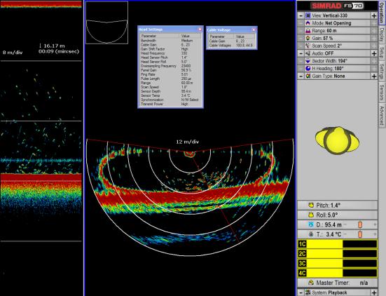
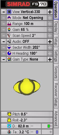
3.2.1 OPERATING CONTROL PANEL PAGE |
|
The main “Operating” control panel allows you to select the sonar you want to control; View Vertical or View Sounder as indicated above. Click on the appropriate display window to activate the sonar you want to control, next position the mouse cursor on the button you want to change, then, click the left mouse button or right mouse button to change the settings.
Kongsberg Mesotech Ltd.
Port Coquitlam, BC - Canada

974-24007001/3.0 |
FS 70 Operators Manual |
Page 3.6 |
FS 70 System Operation |
3.2.2 DISPLAY CONTROL PANEL PAGE |
|
The main “Display” control panel allows you to select the sonar you want to control. To change the value of the system parameter just left or right click the mouse over the button you have selected, move the mouse up or down until the desired button is highlighted and click the left mouse button or right mouse button to activate the new setting.
Kongsberg Mesotech Ltd.
Port Coquitlam, BC - Canada
FS 70 Operators Manual |
974-24007001/3.0 |
FS 70 System Operation |
Page 3.7 |
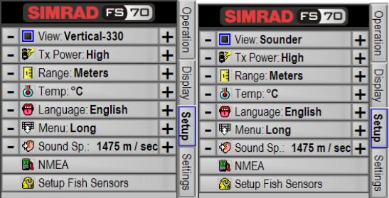
3.2.3 SETUP CONTROL PANEL PAGE |
|
The main “Setup” control panel allows you to select the sonar you want to control. To change the value of the system parameter just left or right click the mouse over the button you have selected, move the mouse up or down until the desired button is highlighted and click the left mouse button or right mouse button to activate the new setting.
Kongsberg Mesotech Ltd.
Port Coquitlam, BC - Canada
974-24007001/3.0 |
FS 70 Operators Manual |
Page 3.8 |
FS 70 System Operation |
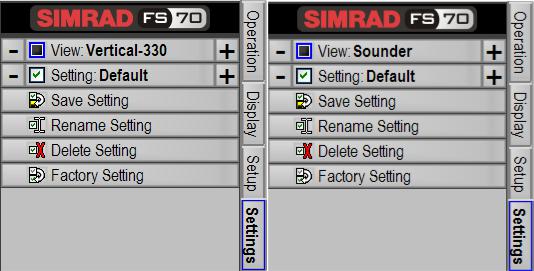
3.2.4 USERS SETTINGS CONTROL PANEL PAGE |
|
The main “Users” control panel allows you to select the sonar you want to control. To change the value of the system parameter, just left or right click the mouse over the button you have selected, move the mouse up or down until the desired button is highlighted and click the left mouse button or right mouse button to activate the new setting.
Note: When you “Save Setting” you automatically save the setting for the vertical and the sounder at the same time.
Kongsberg Mesotech Ltd.
Port Coquitlam, BC - Canada
 Loading...