


 Loading...
INSTRUCTION MANUAL
Robertson AP45
Autopilot
20220042/6/02
This page is intentionally left blank.
NOTE!
Simrad Egersund AS makes every effort to ensure that the information contained within this document is correct. However, our equipment is continuously being improved and updated, so we cannot assume liability for any errors which may occur.
The information contained within this document remains the sole property of Simrad Egersund AS. No part of this document may be copied or reproduced in any form or by any means, and the information contained within is not to be passed on to a third party, without the prior written consent of
Simrad Egersund AS.
Warning
The equipment to which this manual applies must only be used for the purpose for which it was designed. Improper use or maintenance may cause damage to the equipment or injury to personnel. The user must be familiar with the contents of the appropriate manuals before attempting to operate or work on the equipment.
Simrad Egersund AS disclaims any responsibility for damage or injury caused by improper installation, use or maintenance of the equipment.
Simrad Egersund AS |
Telephone: |
+47 51 46 20 00 |
Nyåskaien |
Telefax: |
+47 51 46 20 01 |
P.O. Box 55 |
|
|
N-4379 Egersund, Norway |
|
|

Robertson AP45
Modification record
MODIFICATION RECORD
Robertson AP45 Autopilot
Document revisions
Rev. |
Written by |
Checked by |
Approved by |
||||
|
|
|
|
|
|
|
|
|
Date |
Sign. |
Date |
|
Sign. |
Date |
Sign. |
|
|
|
|
|
|
|
|
January 1996 |
08.01.96 |
N.G. |
08.01.96 |
|
I.K. |
08.01.96 |
Th.H. |
|
|
|
|
|
|
|
|
September 1997 |
08.09.97 |
N.G. |
08.09.97 |
|
I.K. |
08.09.97 |
Th.H. |
|
|
|
|
|
|
|
|
October 1998 |
01.10.98 |
N.G. |
01.10.98 |
|
I.K. |
01.10.98 |
Th.H. |
|
|
|
|
|
|
|
|
September 1999 |
15.09.99 |
N.G. |
15.09.99 |
|
I.K. |
15.09.99 |
Th.H. |
|
|
|
|
|
|
|
|
June 2002 |
29.05.02 |
|
29.05.02 |
|
|
29.05.02 |
|
|
|
|
|
|
|
|
|
|
|
|
|
|
|
||
|
|
Document history |
|
|
|
||
|
|
|
|
|
|
||
Rev. |
|
|
Action/Changes/References |
|
|
||
September 1990 Covers the software versions V1R0, V1R1, V1R2 and V1R3. New rudder feedback RF45 included.
January 1996 Updated to software version V1R4. Major extensions of section 3 and 5. RI40 substitutes RI45. G45 included.
September 1997 Modifications due to improved protection against electro magnetic interference, page 5-1, 5-2, 5-17 and 8-1. J45A grounding page 5-21. Modification on fig. 5-29. “Soft start” function included on page 3-6. Corrected number of bushings on page 5- 26 and page 5-28. Missing length group 60-100 ft included on page 6-4. Corrected text in fig. 6-2. Page 5-33: Switch position 8 and 9 changed to NMEA 0183.
October 1998 Minor corrections on following pages: 2-5, 2-6, 2-11, 2-12, 5-3, 5-8, 5-20, 5-21, 5-31, 5-33, 6-1, 7-1, 7-2, 7-4 and 8-3.
September 1999 RI40 substituted by RI9, RI101 by RI35. RF45 substituted by RF45X. S3 substituted by S35. Removed the NMEA0180, inverse polarity. RFC250 substituted by RFC35NS. New distributor list.
June 2002 Note on page 5-31 included. New distributor list.
To assist us in making improvements to this manual, we would welcome comments and constructive criticisms. Please send all such comments, in writing to:
Simrad Egersund AS
Documentation Department
P.O. Box 55,
N-4379 Egersund
Norway
Simrad Robertson AS
Egersund - Norway

Robertson AP45
Modification record
IMPORTANT!
An autopilot is a very useful navigational aid, but DOES NOT under any circumstance replace a human navigator.
Do not use automatic steering when:
•In heavy traffic areas or in narrow waters
•In poor visibility or extreme sea conditions
•When in areas where use of autopilot is prohibited by law When using an autopilot:
•Do not leave the helm unattended
•Do not place any magnetic material or equipment near magnetic or fluxgate compass used in the autopilot system
Verify at regular intervals course and position of vessel
•Always switch to Standby mode in due time to avoid hazardous situations
Simrad Robertson AS
Egersund - Norway

Robertson AP45 Modification record
Simrad Robertson AS
Egersund - Norway
Robertson AP45 Autopilot |
Page I |
Table of contents |
|
TABLE OF CONTENTS
1. GENERAL INFORMATION.................................................. |
1-1 |
Introduction ................................................................................................................... |
1-1 |
System description......................................................................................................... |
1-1 |
AP45 Control Unit......................................................................................................... |
1-1 |
Heading Sensors ............................................................................................................ |
1-1 |
Rudder Feedback Units ................................................................................................. |
1-2 |
Junction units................................................................................................................. |
1-3 |
Optional equipment ....................................................................................................... |
1-3 |
Remote Controls............................................................................................................ |
1-3 |
Rudder Angle Indicators................................................................................................ |
1-4 |
2. OPERATION OF THE AUTOPILOT................................... |
2-1 |
General .......................................................................................................................... |
2-1 |
Front Panel .................................................................................................................... |
2-1 |
Mode selection .............................................................................................................. |
2-1 |
Parameter setting ........................................................................................................... |
2-3 |
Course selection............................................................................................................. |
2-4 |
Navigating with the AP45.............................................................................................. |
2-5 |
Mixed mode, XTE & CTS............................................................................................. |
2-5 |
XTE mode ..................................................................................................................... |
2-6 |
Steering by bearing to waypoint (CTS) ......................................................................... |
2-8 |
Remote Controls General ............................................................................................ |
2-10 |
F200-40 Remote Control............................................................................................. |
2-10 |
S9 Steering Lever ........................................................................................................ |
2-11 |
FU91 Follow up Steering Lever .................................................................................. |
2-14 |
Fault warnings ............................................................................................................. |
2-16 |
3. DESIGN AND THEORY OF OPERATION......................... |
3-1 |
Automatic Steering ........................................................................................................ |
3-1 |
AP45 Control Unit......................................................................................................... |
3-2 |
CD109 Course Detector ................................................................................................ |
3-2 |
Rudder Feedback Units ................................................................................................. |
3-3 |
RF45X Rudder Feedback Unit ...................................................................................... |
3-3 |
RF14XU Rudder Feedback Unit (optional)................................................................... |
3-3 |
Junction Units................................................................................................................ |
3-4 |
J45S Junction Unit......................................................................................................... |
3-4 |
J45A Electronic Junction Unit....................................................................................... |
3-6 |
4. |
TECHNICAL SPECIFICATIONS ........................................ |
4-1 |
|
AP45 Control Unit......................................................................................................... |
4-1 |
|
CD109 Course Detector ................................................................................................ |
4-2 |
|
RFC35NS Fluxgate compass......................................................................................... |
4-3 |
|
G40A Gyro Interface..................................................................................................... |
4-4 |
|
G45 Gyro Interface........................................................................................................ |
4-4 |
|
FI100-40 Fluxgate Interface .......................................................................................... |
4-5 |
|
RF45X Rudder Feedback Unit ...................................................................................... |
4-5 |
|
RF14XU Rudder Feedback Unit ................................................................................... |
4-6 |
|
J45S Junction Unit......................................................................................................... |
4-7 |
|
J45A Junction Unit ........................................................................................................ |
4-7 |
|
S9 Steering Lever .......................................................................................................... |
4-8 |
|
FU91 Steering Lever ..................................................................................................... |
4-8 |
|
S35 Steering Lever ........................................................................................................ |
4-9 |
|
F1/2 Remote Control ................................................................................................... |
4-10 |
|
F200-40 Remote Control............................................................................................. |
4-10 |
|
RI35 Rudder Angle Indicator ...................................................................................... |
4-11 |
Simrad Robertson AS
Egersund - Norway
Page II |
|
Robertson AP45 Autopilot |
|
|
|
Table of contents |
|
|
RI9 Rudder Angle Indicator ........................................................................................ |
|
4-12 |
5. |
INSTALLATION ..................................................................... |
|
5-1 |
|
Unpacking and handling................................................................................................ |
|
5-1 |
|
General .......................................................................................................................... |
|
5-1 |
|
AP45 Control Unit......................................................................................................... |
|
5-1 |
|
Connector assemble....................................................................................................... |
|
5-2 |
|
Heading sensors............................................................................................................. |
|
5-4 |
|
General .......................................................................................................................... |
|
5-4 |
|
Magnetic compass ......................................................................................................... |
|
5-4 |
|
RFC35NS Fluxgate Compass ........................................................................................ |
|
5-6 |
|
Mounting ....................................................................................................................... |
|
5-6 |
|
Connection..................................................................................................................... |
|
5-7 |
|
Calibration..................................................................................................................... |
|
5-7 |
|
Alignment ...................................................................................................................... |
|
5-8 |
|
FI100-40 Fluxgate Interface .......................................................................................... |
|
5-8 |
|
G40A Gyro Interface Unit............................................................................................. |
|
5-9 |
|
G45 Gyro Interface Unit.............................................................................................. |
|
5-11 |
|
RGC Signal Interface Unit........................................................................................... |
|
5-12 |
|
RF45X Rudder Feedback Unit .................................................................................... |
|
5-13 |
|
RF14XU Rudder Feedback Unit ................................................................................. |
|
5-14 |
|
J45S Junction Unit....................................................................................................... |
|
5-19 |
|
J45A Junction Unit ...................................................................................................... |
|
5-21 |
|
Optional equipment ..................................................................................................... |
|
5-26 |
|
F200-40 Remote Control............................................................................................. |
|
5-26 |
|
S9 Steering Lever ........................................................................................................ |
|
5-26 |
|
FU91 Steering Lever ................................................................................................... |
|
5-28 |
|
F1/2 Remote Control ................................................................................................... |
|
5-30 |
|
S35 Steering Lever ...................................................................................................... |
|
5-30 |
|
RI9 Rudder Angle Indicator ........................................................................................ |
|
5-31 |
|
RI35 Rudder Angle Indicator ...................................................................................... |
|
5-33 |
|
Panel mounting............................................................................................................ |
|
5-34 |
|
Bracket mounting ........................................................................................................ |
|
5-34 |
|
Illumination ................................................................................................................. |
|
5-35 |
|
Zero adjust................................................................................................................... |
|
5-35 |
|
Reversed deflection ..................................................................................................... |
|
5-35 |
|
Connection to Navigation Receiver............................................................................. |
|
5-36 |
|
Watch alarm ................................................................................................................ |
|
5-37 |
6. |
START-UP PROCEDURE/ COMMISSIONING................. |
6-1 |
|
|
Power ON...................................................................................................................... |
|
6-1 |
|
Rudder Feedback Adjustment........................................................................................ |
|
6-1 |
|
Direction of Rudder Movement..................................................................................... |
|
6-1 |
|
Rudder speed ................................................................................................................. |
|
6-2 |
|
Course Detector Alignment ........................................................................................... |
|
6-2 |
|
Selection of parameter settings...................................................................................... |
|
6-2 |
|
Select language.............................................................................................................. |
|
6-3 |
|
Type of Heading Sensor ................................................................................................ |
|
6-4 |
|
Off Course limit............................................................................................................. |
|
6-4 |
|
Vessel's length ............................................................................................................... |
|
6-4 |
|
Counter rudder............................................................................................................... |
|
6-5 |
|
Rudder limit................................................................................................................... |
|
6-5 |
|
Rudder deadband........................................................................................................... |
|
6-5 |
|
NMEA-format ............................................................................................................... |
|
6-5 |
|
Disengage of autotrim-function in WORK-mode.......................................................... |
|
6-5 |
|
Disengage of Off Course alarm in Work mode ............................................................. |
|
6-6 |
|
Sea Trial ........................................................................................................................ |
|
6-6 |
Simrad Robertson AS
Egersund - Norway
Robertson AP45 Autopilot |
Page III |
Table of contents |
|
7. |
TROUBLE SHOOTING ......................................................... |
7-1 |
|
Fault warnings ............................................................................................................... |
7-1 |
|
Debug/Adjust mode....................................................................................................... |
7-5 |
8. SPARE PARTS AND DRAWINGS....................................... |
8-1 |
|
|
AP45 Control Unit......................................................................................................... |
8-1 |
|
CD109 Course Detector ................................................................................................ |
8-4 |
|
G40A Gyro Interface..................................................................................................... |
8-5 |
|
G45 Gyro Interface........................................................................................................ |
8-7 |
|
FI100-40 Fluxgate Interface .......................................................................................... |
8-9 |
|
RF45X Rudder Feedback .............................................................................................. |
8-9 |
|
RF14XU Rudder Feedback Unit ................................................................................... |
8-9 |
|
J45S Junction Unit....................................................................................................... |
8-10 |
|
J45A Junction Unit ...................................................................................................... |
8-12 |
|
F200-40 Remote Control............................................................................................. |
8-14 |
|
S9 Steering Lever ........................................................................................................ |
8-16 |
|
S35 Steering Lever ...................................................................................................... |
8-16 |
|
FU91 Steering Lever ................................................................................................... |
8-16 |
|
RI9 Rudder Angle Indicator ........................................................................................ |
8-17 |
|
RI35 Rudder Angle Indicator ...................................................................................... |
8-17 |
9. |
SALES AND SERVICE WORLDWIDE (990901)................... |
9-1 |
LIST OF DRAWINGS
FIG. 1-1 AP45 SYSTEM LAYOUT - BASIC SYSTEM WITH OPTIONS |
................................1-1 |
FIG. 2-1 AP45 CONTROL UNIT - FRONT PANEL ........................................................... |
2-1 |
FIG. 3-1 AUTOPILOT PRINCIPLE DIAGRAM ................................................................... |
3-1 |
FIG. 3-2 PROCESSOR CONTROLLED AUTOPILOT ........................................................... |
3-1 |
FIG. 3-3 COURSE DETECTOR PRINCIPLE...................................................................... |
3-2 |
FIG. 3-4 RF45X PRINCIPLE ......................................................................................... |
3-3 |
FIG. 3-5 BASIC SYSTEM................................................................................................ |
3-4 |
FIG. 3-6 SOLENOIDS WITH POSITIVE COMMON ............................................................ |
3-5 |
FIG. 3-7 SOLENOIDS WITH NEGATIVE COMMON........................................................... |
3-5 |
FIG. 3-8 J45A PRINCIPLE ............................................................................................ |
3-6 |
FIG. 4-1 AP45 CONTROL UNIT - DIMENSIONS............................................................. |
4-1 |
FIG. 4-2 CD109 COURSE DETECTOR............................................................................ |
4-2 |
FIG. 4-3 RFC35NS - DIMENSIONS .............................................................................. |
4-3 |
FIG. 4-4 G40A GYRO INTERFACE - DIMENSIONS ......................................................... |
4-4 |
FIG. 4-5 FI100-40 FLUXGATE INTERFACE - DIMENSIONS ........................................... |
4-5 |
FIG. 4-6 RF45X RUDDER FEEDBACK - DIMENSIONS ................................................... |
4-5 |
FIG. 4-7 RF14XU RUDDER FEEDBACK UNIT - DIMENSIONS........................................ |
4-6 |
FIG. 4-8 J45S/J45A/G45 - DIMENSIONS ..................................................................... |
4-7 |
FIG. 4-9 S9 STEERING LEVER - DIMENSIONS .............................................................. |
4-8 |
FIG. 4-10 FU91 STEERING LEVER - DIMENSIONS....................................................... |
4-8 |
FIG. 4-11 S35 STEERING LEVER - DIMENSIONS .......................................................... |
4-9 |
FIG. 4-12 F1/2 REMOTE CONTROL - DIMENSIONS..................................................... |
4-10 |
FIG. 4-13 F200-40 REMOTE CONTROL DIMENSIONS................................................. |
4-10 |
FIG. 4-14 RI35 RUDDER ANGLE INDICATOR - DIMENSIONS...................................... |
4-11 |
FIG. 4-15 RI9 RUDDER ANGLE INDICATOR - DIMENSIONS........................................ |
4-12 |
FIG. 5-1 AP45 CONTROL UNIT - PANEL MOUNT ......................................................... |
5-1 |
FIG. 5-2 AP45 CONTROL UNIT - BRACKET MOUNTING ............................................... |
5-1 |
FIG. 5-3 CONTROL UNIT - CONNECTOR MOUNTING...................................................... |
5-2 |
FIG. 5-4 AP45 EXTERNAL CABLING DIAGRAM ............................................................. |
5-3 |
FIG. 5-5 CD109 COURSE DETECTOR - MOUNTING ...................................................... |
5-5 |
FIG. 5-6 AP45/RFC35NS - CONNECTION................................................................... |
5-7 |
FIG. 5-7 RFC35NS - INTERNAL CONNECTION ........................................................... |
5-7 |
Simrad Robertson AS
Egersund - Norway
Page IV |
Robertson AP45 Autopilot |
||
|
Table of contents |
||
|
FIG. 5-8 AP45/FI100-40 FLUXGATE INTERFACE - WIRING......................................... |
5-8 |
|
|
FIG. 5-9 G40A GYRO INTERFACE CONNECTIONS........................................................ |
5-9 |
|
|
FIG. 5-10 G40A PC-BOARD - SWITCH LOCATION....................................................... |
5-10 |
|
|
FIG. 5-11 CONNECTION TO G45 EXCITATED SYNCHRO TRANSMITTER....................... |
5-11 |
|
|
FIG. 5-12 CONNECTION TO GYRO EXCITATED SYNCHRO TRANSMITTERS ................... |
5-11 |
|
|
FIG. 5-13 G45 INPUT/OUTPUT ................................................................................... |
5-12 |
|
|
FIG. 5-14 AP45/RGC SIGNAL INTERFACE UNIT - WIRING........................................ |
5-12 |
|
|
FIG. 5-16 RF45X RUDDER FEEDBACK UNIT - MOUNTING........................................ |
5-13 |
|
|
FIG. 5-17 RF14XU - MOUNTING ............................................................................... |
5-14 |
|
|
FIG. 5-18 RF45 TEMPLATE SCALE 1:1 ...................................................................... |
5-15 |
|
|
FIG. 5-19 SCREEN TERMINATION............................................................................... |
5-17 |
|
|
FIG. 5-20 RF14XU INTERNAL WIRING ...................................................................... |
5-18 |
|
|
FIG. 5-21 RF14XU/J45S - WIRING ........................................................................... |
5-19 |
|
|
FIG. 5-22 J45A JUNCTION UNIT GROUNDING ........................................................... |
5-21 |
|
|
FIG. 5-23 AP45 WIRING DIAGRAM - BASIC SYSTEM (015936H)................................. |
5-22 |
|
|
FIG. 5-24 AP45 WIRING DIAGRAM - SOLENOIDS WITH POSITIVE COMMON (015936H)5-23 |
||
|
FIG. 5-25 AP45 WIRING DIAGRAM - SOLENOIDS WITH NEGATIVE COMMON (015936H)5-24 |
||
|
FIG. 5-26 AP45/J45 WIRING DIAGRAM...................................................................... |
5-25 |
|
|
FIG. 5-27 F200-40/AP45 - WIRING DIAGRAM............................................................ |
5-26 |
|
|
FIG. 5-28 S9 MOUNTING ........................................................................................... |
5-26 |
|
|
FIG. 5-29 S9/AP45 - WIRING DIAGRAM ..................................................................... |
5-27 |
|
|
FIG. 5-30 S9 STEERING LEVER - INTERNAL WIRING.................................................. |
5-27 |
|
|
FIG. 5-31 FU91 MOUNTING ...................................................................................... |
5-28 |
|
|
FIG. 5-32 FU91 WITHOUT MODE SWITCHING ............................................................ |
5-28 |
|
|
FIG. 5-33 FU91 WITH MODE SWITCHING................................................................... |
5-29 |
|
|
FIG. 5-34 FU91 MULTIPLE INSTALLATION................................................................ |
5-29 |
|
|
FIG. 5-35 S35, F1/2 - AP45 - WIRING DIAGRAM........................................................ |
5-30 |
|
|
FIG. 5-36 AP45 WIRING DIAGRAM - J3 W/MULTIPLE INPUT...................................... |
5-30 |
|
|
FIG. 5-37 RI9 WIRING DIAGRAM................................................................................ |
5-31 |
|
|
FIG. 5-38 RI9 INPUT SIGNAL SELECTION .................................................................. |
5-32 |
|
|
FIG. 5-39 RI35-J45A WIRING DIAGRAM................................................................... |
5-33 |
|
|
FIG. 5-40 RI35-J45S WIRING DIAGRAM ................................................................... |
5-33 |
|
|
FIG. 5-41 PANEL MOUNTING...................................................................................... |
5-34 |
|
|
FIG. 5-42 RI35 BRACKET MOUNTING ....................................................................... |
5-34 |
|
|
FIG. 5-43 N40 NAV. INTERFACE MOUNTING (FOR MAIN PCBS WITH REVISION UP TO |
||
|
AND INCLUDING REVISION G) ............................................................................. |
5-36 |
|
|
FIG. 5-44 AP45/NAVIGATION RECEIVER - WIRING .................................................... |
5-37 |
|
|
FIG. 5-45 WA9 CIRCUIT/WIRING DIAGRAM ............................................................... |
5-37 |
|
|
FIG. 6-1 AP45 INSTALLATION LOOP ............................................................................ |
6-3 |
|
|
FIG. 6-2 COUNTER RUDDER SETTINGS......................................................................... |
6-7 |
|
|
FIG. 8-1 AP45 EXPLODED VIEW .................................................................................. |
8-2 |
|
|
FIG. 8-2 AP45 SIGNAL REFERENCE ............................................................................. |
8-3 |
|
|
FIG. 8-3 CD109 - SPARE PARTS ................................................................................... |
8-4 |
|
|
FIG. 8-4 G40A COMPONENT REFERENCE .................................................................... |
8-5 |
|
|
FIG. 8-5 G40A CIRCUIT DIAGRAM ............................................................................... |
8-6 |
|
|
FIG. 8-6 G45 COMPONENT REFERENCE....................................................................... |
8-7 |
|
|
FIG. 8-7 G45 CIRCUIT DIAGRAM .................................................................................. |
8-8 |
|
|
FIG. 8-8 RF14XU - SPARE PARTS ................................................................................ |
8-9 |
|
|
FIG. 8-9 J45S COMPONENT REFERENCE ................................................................... |
8-10 |
|
|
FIG. 8-10 J45S CIRCUIT DIAGRAM............................................................................. |
8-11 |
|
|
FIG. 8-11 J45A COMPONENT REFERENCE................................................................. |
8-12 |
|
|
FIG. 8-12 J45A CIRCUIT DIAGRAM ............................................................................ |
8-13 |
|
|
FIG. 8-13 F200-40 COMPONENT REFERENCE............................................................ |
8-14 |
|
|
FIG. 8-14 F200-40 CIRCUIT DIAGRAM ....................................................................... |
8-15 |
|
|
FIG. 8-15 RI40 EXPLODED VIEW ............................................................................... |
8-17 |
|
Simrad Robertson AS
Egersund - Norway
Robertson AP45 Autopilot |
Page 1-1 |
General Information |
|
Introduction
System description
AP45 Control Unit
1. GENERAL INFORMATION
Today Simrad manufacture a complete range of autopilots for all types of vessels, from leisure boats up to advanced steering systems for merchant marine vessels. Our factory for these products – branded Robertson – is located in Egersund, on the south/west coast of Norway. The company’s involvement in autopilots began in 1953 with equipment for the North Sea fishing fleet.
In 1982 the world's first microprocessor based autopilot, the Robertson AP100, was introduced and shortly after the AP9 and AP40 systems followed.
The AP45 autopilot described in this document is based on the experience with the AP40 and the AP9 models. A series of improvements based upon this experience has been implemented in the new model and special attention has been paid to simplified operation.
The standard AP45 system consists of the following units (refer to Fig. 1-1):
1.AP45 Control Unit with accessories
2.Heading sensor
3.Rudder Feedback Unit with transmission link
4.Junction Unit
Fig. 1-1
AP45 System layout - Basic system with options
All settings and operation of the autopilot take place on the control unit. In addition to push buttons it has two LCD-displays and a course selector knob on the front panel. The control unit is made of seawater resistant aluminium and has a polyester coating to protect it against the environment. The main electronics are located in the control unit, and connection to other system components are by high quality connectors to facilitate reliability and easy maintenance.
Heading Sensors
The AP45 autopilot can be used with one of three different types of heading sensors:
Simrad Robertson AS
Egersund - Norway
Page 1-2 |
Robertson AP45 Autopilot |
|
General Information |
Rudder Feedback
Units
1.Magnetic compass with CD109 Course Detector
2.RFC35NS Fluxgate compass*
3.Gyrocompass (using optional G40A or G45 Interface Unit)
*) For other types of Fluxgate Compass the FI100-40 Fluxgate Interface must be used.
CD109 Course Detector
CD109 is a magnetic sensor in moulded plastic which is mounted on the vessel's magnetic compass to transfer the heading to the control unit.
RFC35NS Fluxgate Compass
This is an electronic sense unit with NMEAand sine/cosine output. The compass has a 0,3 m ”pigtail” cable. RFC35NS substitutes the RFC250 Fluxgate compass. RFC250 cable (P/N 20183554) is necessary at new installations.
G40A/G45 Gyro Interface Unit
The gyro interface unit is connected between the AP45 and a gyro compass. It utilises the repeater signal output from the gyro compass to generate a sine/cosine heading signal for the autopilot.
G40A to be used with stepper or geared synchro signal. G45 to be used with synchro 1:1 signal.
FI100-40 Fluxgate Interface
FI100-40 is an interface unit to be connected between the AP45 and an electronic fluxgate compass with sine/cosine output, e.g. VDO, Marinex, Sowester, Brooks & Gatehouse.
RF45X Rudder Feedback Unit
This unit transmits two electrical signals proportional to the rudder angle. One signal operates as a feedback for the autopilot, the other as drive signal for rudder angle indicators. The unit is mounted close to the rudder stock and is mechanically connected to the rudder by the T45 Transmission link.
RF14XU Rudder Feedback Unit
This unit can replace the RF45 Rudder Feedback Unit in installations where a more rugged construction of the feedback unit is preferred. Besides electronic circuitry to generate feedback signals for the autopilot and rudder angle indicators it has been provided with 2 sets of limit switches. RF14XU can not drive the RI101 Rudder Angle Indicator, but all other types of Robertson indicators.
Simrad Robertson AS
Egersund - Norway
Robertson AP45 Autopilot |
Page 1-3 |
General Information |
|
Junction units Except for a bigger cabinet, the J45S and the J45A junction units described in this manual are identical to the previous versions, J200S-40 and J101A-40 respectively.
J45S Junction unit
The J45S Junction Unit will operate continuously running hydraulic power units with directional valves as Robertson RPU3 or similar. The unit contains a printed circuit board with terminal block, fuse, galvanic isolated solid state output to switch the solenoids and start relay for the Power Unit. All mounted in an aluminium cabinet with polyester coating.
J45A Electronic Junction Unit
The unit provides variable speed control of reversible hydraulic power units (e.g. Robertson RPU80, RPU100 RPU160 or RPU200) and mechanical power units (MRD100 or HLD2000). The unit consists of a printed circuit board with terminal block, fuse and drive electronics, mounted in the same type of aluminium cabinet as the J45S.
Optional equipment A series of options are available for the basic AP45 system.
Remote Controls S9 Non-follow-up (NFU) steering lever
S9 is a splash proof steering lever for bulkhead or console mounting. The unit is constructed of a machined aluminium housing. The internal mechanism of the S9 permits locking of the lever in the mid-position to avoid inadvertent operation. When connected to the AP45, the S9 can also be used to switch the mode of the autopilot when the lever is pulled out or pushed in.
FU91 Follow-Up (FU) steering lever
FU91 is a splash proof steering lever for bulkhead or console mounting. The unit has a 45-0-45 degrees dial and a Push to take command button. By positioning the lever, a desired rudder angle can be set without using a rudder angle indicator. Dimensions and design are the same as the S9, and it has a mid-position detent.
S35 Non Follow Up (NFU) Steering Lever
S35 is designed for indoor and outdoor bulkhead mounting. The lever is spring loaded to midposition. It also has a “Mode” button that is not used when connected to AP45.
F1/2 Remote Control (NFU)
F1/2 is a handheld control for push button steering, fitted with a rubber grip. It is made of cast seawater resistant aluminium and fitted with a 10 meter (30 ft.) cable.
F200-40 Remote Control
F200-40 is a multifunction hand held remote control with a 4-digit LCD display and a course selector knob to set course or rudder angle. It has push buttons for power steering, course adjustment and mode selection between power steering, dodging and auto steering. The unit consists of a PC board mounted in a splash proof aluminium cabinet fitted with a 7m (23 ft) cable connecting to the control unit.
Simrad Robertson AS
Egersund - Norway
Page 1-4 |
Robertson AP45 Autopilot |
|
General Information |
Rudder Angle
Indicators
RI9 Rudder Angle Indicator
RI9 is an analogue indicator showing the rudder position at angles up to 45 degrees on each side of midship position. The scaling is 2 degrees pr. division.
The scale illumination is adjustable by a knob on the front.
The housing is constructed of painted aluminium intended for either bulkhead or console mounting. The splash proof construction is suitable for exposed mounting locations.
RI35 Rudder Angle Indicator
RI35 is an analogue indicator showing the rudder position at angles up to 45 degrees on each side of midship position. The scaling is five degrees pr. division.
A front panel key is used for rudder zero adjustment and illumination adjustment.
The splash proof construction allows panel, bulkhead or bracket mounting in exposed locations, such as bridge wings as well as wheel house and engine room.
RI35 is delivered with a 20 meter (65 feet) cable.
Simrad Robertson AS
Egersund - Norway
Robertson AP45 Autopilot |
Page 2-1 |
Operation |
|
2. OPERATION OF THE AUTOPILOT
General
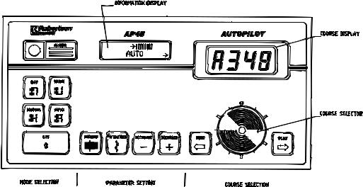
Fig. 2-1
AP45 Control Unit - front panel
Front Panel
Mode selection
AP45 autopilot is operated by means of keypad push buttons on the front panel. To facilitate operation, the buttons are marked with text and symbols. The buttons are backlighted, activated mode buttons being brighter than the others.
Course selection is made by the rotary Course Selector Knob. Course adjustments in steps of one degree can be achieved by the port or starboard push buttons.
The front panel has two LCD displays, referred to as the information display (left side) and the course display (right side). An alarm buzzer and an alarm reset button is also on the front panel.
A few simple operations like pressing a button and/or turning the Course Selector Knob is required in ordinary use of the autopilot. All other instructions and data required for the operation is stored in the autopilot at delivery from Robertson.
The front panel can be divided into three sections: Mode selection, Parameter setting and Course selection.
Together with the OFF-button and the 4 mode buttons, this section also contains an alarm buzzer and ALARM RESET-button.
MANUAL
The MANUAL button serves two purposes. It switches on the autopilot and selects manual steering mode. In this mode the Course Display gives a digital readout of compass heading, while the vessel can be steered manually by helm or steering lever(s).
AUTO
The AUTO-mode is used under normal conditions when the boat is steered automatically on a preset course.
When the AUTO-button is pressed, the autopilot selects the current vessel heading as "course to steer".
Simrad Robertson AS
Egersund - Norway
Page 2-2 |
Robertson AP45 Autopilot |
|
Operation |
Any difference between course to steer and the vessel's actual heading will then be shown as a bargraph in the Information Display. One bar equals one degree.
Rudder commands are indicated by an arrow in the lower left or right corner of the information display depending upon which direction the autopilot commands the rudder to move.
WORK
The WORK-mode is an automatic mode to be used under operational conditions different from those normally found when a vessel is under motor power on a preset course. Examples are trawling, towing, sailing, slow speed etc.
In WORK-mode the PORTand STBD-buttons can be used for immediate rudder off-set (trim) if necessary. This manual off-set compensates for the built-in autotrim which needs time to build up the appropriate off-set.
The Information Display shows the off-set value when the PORTor STBD button is pressed.
Boats under sail power and some trawlers may need a rudder off-set when steered by hand. To avoid cancellation of the rudder off-set when changing to automatic steering, the WORK-mode can be selected directly from MANUAL-mode. The rudder off-set is then maintained as "on course" reference. This off-set is also maintained when changing from WORK to NAV mode.
If the AUTO-mode is selected from MANUAL-mode, the rudder is first taken to midposition before a sufficient off-set of the rudder is built-up automatically (autotrim).
A different RUDDER value may be preferred in WORK-mode as compared to that in AUTO-mode. The WORK-mode value will be stored in the AP45 memory for later use.
Note!
Pair-trawling that requires manual trim only, will also require that the autotrim be disabled. Refer to “Disengage of autotrim-function in WORK-mode”, page 6-5, for specific details.
NAV
NAV-mode is used when a navigation receiver is connected to the autopilot for automatic waypoint steering. To be able to use the NAV-mode with older AP45 (below s.n. 4000), the main PCB must be equipped with the N40 Navigation Interface.
When the NAV-mode is selected, the AP45 automatically monitors the signals from the navigation system. If the signals are absent or in a different format than the data format selected in the AP45, an alarm will be given to alert the operator. See “Navigating with the AP45” page 2-5.
OFF
The autopilot is switched off by pressing the OFF-button for 2 seconds, during which time the alarm will sound. The alarm ceases when the AP45 is switched off. If the OFF-button is released before two seconds have elapsed, the autopilot will continue to operate as before and the alarm signal is automatically reset.
Rudder commands will stop as long as the OFF-button is pressed. All pre-set parameters in the autopilot are stored while the unit is switched off.
Simrad Robertson AS
Egersund - Norway
Robertson AP45 Autopilot |
Page 2-3 |
|||||
Operation |
|
|
|
|
|
|
|
ALARM |
|
||||
|
The acoustic alarm is reset by pressing the red alarm push button. |
|
||||
|
Alarm messages shown on the information display are described under “Fault |
|||||
|
warnings”, page 2-16. |
|
||||
Parameter setting |
General |
|
||||
|
The middle section of the AP45 control unit contains 4 push buttons and an |
|||||
|
Information Display. The display shows selected mode, deviation from set course, |
|||||
|
parameter settings and other user information. When RUDDER or WEATHER |
|||||
|
buttons are pressed, the display shows which button has been activated and to |
|||||
|
what level the value has been set by the number of bars as well as in plain figures. |
|||||
|
The display returns to normal read-out, showing the selected mode one minute |
|||||
|
after the last press on one of the buttons. |
|
||||
|
The text in the Information Display can be in one of five selectable languages: |
|||||
|
English, French, German, Spanish and Norwegian (see “Select language”, page 6- |
|||||
|
3. |
|
|
|
|
|
|
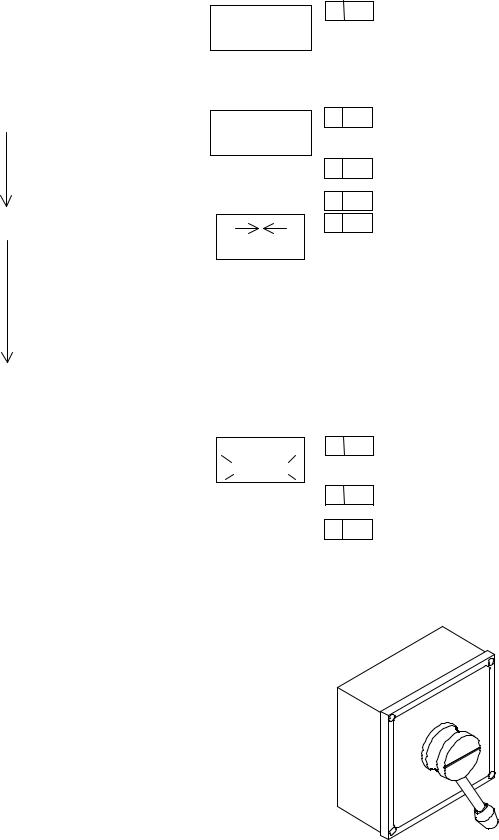
Turn on |
|
||||
|
Turn on the AP45 by pressing the MANUAL button. The information display will |
|||||
|
show for approx. three seconds: |
|
||||
|
|
|
|
|
|
|
|
|
SOFTWARE V_R_ |
|
|
|
|
|
|
MANUAL |
|
|
|
|
|
|
|
|
|
|
|
|
Then it switches to: |
|
||||
|
|
|
|
|
|
|
|
|
NON FOLLOW UP |
|
|
||
|
|
MANUAL |
|
|
||
|
|
|
|
|
|
|
|
If the autopilot is connected to and set up for a gyrocompass with geared synchro |
|||||
|
or stepper signal, the display will show at turn on: |
|
||||
|
|
|
|
|
|
|
|
|
GYROADJUST |
|
|
||
|
|
PRESS +/- |
|
|
||
|
Use the + or - button until the autopilot display shows the same heading as the |
|||||
|
gyrocompass. |
|
||||
|
Then press the MANUAL button and the display will again show: |
|
||||
|
|
|
|
|
||
|
|
NON FOLLOW UP |
|
|
|
|
|
|
MANUAL |
|
|
|
|
|
When clear of obstacles and in open waters, steer your vessel on course and press |
|||||
|
the AUTO button. |
|
||||
|
The display will now show: |
|
||||
|
|
|
|
|||
|
|
→ ← |
|
|
||
|
|
AUTOMATIC |
|
|
||
|
and the autopilot will automatically keep your vessel on course. |
|
||||
|
INCREASE and DECREASE |
|
||||
Simrad Robertson AS
Egersund - Norway

Page 2-4 |
Robertson AP45 Autopilot |
|
Operation |
These buttons are used to alter various settings. Each time one button is pressed, the value shown on the Information Display, will increase (+) or decrease (—) by one unit. The value is also shown as a graphical bar. If a button is pressed for more than two seconds, the value will automatically increase or decrease until the button is released.
RUDDER
When the RUDDER button is pressed, the Information Display shows selected RUDDER value. The RUDDER value sets the ratio between rudder angle and heading error (p-factor).
Example: If RUDDER is set to 1.0 and there is a heading error of 2 degrees, the rudder angle will be 2 degrees. (Heading error x RUDDER value = rudder angle).
The correct RUDDER setting is dependant upon the size and speed of the vessel. The RUDDER value should increase with decreasing speed.
RUDDER should be set separately in WORK-mode, to optimise the autopilot performance.
Examples of incorrect RUDDER settings:
A value which is too low gives relatively large and slow oscillations (s-ing) around set course, and several rudder commands are given in the same direction before the vessel is back on course.
A value which is too high will give quick and in worst case increasing oscillations (s-ing) around set course.
A
B
The correct setting of RUDDER will be approximately in the middle of the settings described in A and B above.
WEATHER
The WEATHER setting determines the amount of degrees the vessel may fall off the set course before any response is given from the rudder. In calm weather it should be set to OFF which means that theoretically the autopilot allows no deviation from set course. The WEATHER value should be increased with increasing sea state.
In conditions where active steering is required, (e.g. following sea condition), the value should be reduced.
Course selection The course selection section on the autopilot consists of a course display, a course selector knob and two course adjustment buttons, PORT and STBD.
The Course Display gives a readout of actual ships heading in MANUAL-mode and set course in AUTO-, WORKand NAV-mode. The selected mode is also shown to the left on the display by the same letter as on the mode buttons.
The course selector knob is used for major course changes in AUTOand WORKmode. To activate the knob it must be pressed down, released, and then turned. Clockwise turns gives a starboard course change and vice versa. One revolution on the course selector knob is equal to a 60 degree course change. If the knob is not turned within 10 seconds, it has to be pressed again.
Simrad Robertson AS
Egersund - Norway
Robertson AP45 Autopilot |
Page 2-5 |
Operation |
|
Navigating with the AP45
The PORT and STBD push buttons are for minor course adjustments, pressed once gives a one degree course change in the appropriate direction. In WORKmode however, the buttons are used for manual rudder trim, and course changes can therefore only be made by the course selector knob.
The AP45 has the capability to use steering information from an external navigator (GPS, LORAN, Plotter) to direct the boat to a specific waypoint location, or through a route of waypoints. In the NAV mode, the AP45 uses the heading sensor as it's primary source of heading for course keeping. The steering information received from the external navigator alters the set course to direct the AP45 to the destination waypoint.
Mixed mode, XTE & CTS
Note!
Navigational steering must only be used in open waters. The process of having an external navigation receiver direct an autopilot can be a slow acting process. By selecting the NAV mode, the AP45 is set for automatic steering on the current set course and then waits for the user to accept the course change to the destination waypoint.
To obtain satisfactory navigation steering, the following points must be fulfilled prior to entering the NAV mode:
•The AP45 autosteering must be tested and found satisfactory.
•The navigation receiver must be operating and the navigation system (GPS, LORAN, Decca) must be in full operating mode with adequate signal characteristics for valid position and steering data.
•The magnetic compass or Fluxgate must have a minimum of deviation.
•At least one waypoint must be entered and selected as the current waypoint in the navigation receiver.
The AP45 is from the factory set up to steer in mixed mode operation (CTS & XTE). This combines the straight steering capability of cross track error (XTE) steering in conjunction with the turning capability of bearing mode steering (CTS).
When operating the AP45 in NAV mode to automatically steer through a route of waypoints, it will steer to the first waypoint in the route after you accept the first waypoint as the location to steer to. When you arrive at the waypoint, you will need to verify that the upcoming course change is acceptable. Verification is performed by pressing the Alarm reset button after the alert screen is displayed. If no verification is received, the AP45 will continue on the current set course in AUTO mode.
Simrad Robertson AS
Egersund - Norway
Page 2-6 |
Robertson AP45 Autopilot |
|
Operation |
|
GPS satellite |
00° ON TRACK |
04°XTE=R0.01NM |
NAVIGATION |
NAVIGATION |
INFO DISPLAY |
INFO DISPLAY |
XTE |
WAYPOINT 3 |
WAYPOINT 1 |
New heading= 70° |
Heading=100° |
|
WAYPOINT 2 |
|
ALARM
RESET
ACCEPT CHANGE? |
RESET |
10MINCHG 30° |
Y: RESET N: AUTO |
|
NAVIGATION |
INFO DISPLAY |
INFO DISPLAY |
|
COURSE DISPLAY |
|
Note! |
|
Steering through a route of waypoints with the AP45 allows you the total flexibility |
|
for automatic waypoint sequencing, but combines the safety feature of requiring |
|
operator acknowledge for course changes in excess of 10 degrees. |
|
If the AP45 is connected to a Nav. receiver that does not transmit a message with |
|
bearing to next waypoint, it will pick a XTE message and steer on Cross Track |
|
Error only. In that case you have to revert to AUTO mode at each waypoint and |
|
manually change set course to equal bearing to next waypoint and then select NAV |
|
mode again. |
XTE mode |
When the AP45 steers using cross track error only, it corrects the set course in |
|
order to keep the vessel on a straight track between two waypoints. Bearing |
|
change at waypoints must be made manually by temporarily go to Auto mode - |
|
change set course - and revert to Nav. mode. |
|
Use the following procedure for XTE steering: |
|
1. Enter the desired bearing line(s) to the Nav. receiver using the present position |
|
and the first waypoint or destination. Distance between waypoints should be of |
|
minimum 2-3 n.m. Otherwise there may not be sufficient time for the system to |
|
calculate the XTE, and for the autopilot to alter the course and bring the vessel |
|
onto the bearing line again. |
|
2. Read the calculated bearing to waypoint from the Nav.receiver. |
|
3. Select AUTO-mode on the AP45, and set the course to the waypoint showed on |
|
the navigation receiver. |
|
Before going to step 4, ensure that the XTE is within +/- 0.1 n.m. to avoid |
|
hazardous course change when selecting NAV-mode. |
|
4. Select NAV-mode on the AP45. The autopilot now automatically changes the |
|
set course to reduce the Cross Track Error (XTE) to zero. The information |
|
display shows the number of degrees the autopilot has changed the set course, |
|
and the XTE in 1/100's of a nautical mile. Note that the display readout will be |
|
delayed, depending upon the NAV. FILTER setting. |
Simrad Robertson AS
Egersund - Norway
Robertson AP45 Autopilot |
Page 2-7 |
Operation |
|
Example:
05° XTE=R 0.02Nm
NAVIGATION
R indicates that the vessel is located to the right of the bearing line, and L indicates to the left of the bearing line.
00° ON TRACK NAVIGATION
05° is the number of degrees course correction relative to initial set course. As the vessel approaches the bearing line, the correction value decreases and when the vessel is on track, the information display shows:
Note!
The display may show X number of degrees course correction even if it says “ON
TRACK”.
5.As the vessel gets within the arrival circle set on the navigational receiver, or as the vessel passes the perpendicular line to the waypoint, the receiver transmits a "data not valid" signal to the autopilot. An alarm will then activate and the course to steer will no longer be updated.
To proceed to the next waypoint, the procedure should be repeated from step 2 onwards.
Procedure:
•Reset the alarm on the autopilot and navigational receiver.
•Select “AUTOPILOT” mode on the autopilot
•Use Course Change knob/buttons on the autopilot to set the new course given by the Nav. receiver.
•Press “NAV”
NOTE!
Navigational steering is a slow acting process and the vessel normally follows the bearing line with a deviation of ±0.02 - 0.03 n.m.(40-50 meters). Higher deviation may temporarily occur due to rapid change of current, wind, speed or at start-up from a position off the track line.
05° XTE = R0.02NM
WAYPOINT 1 |
NAVIGATION |
WAYPOINT 3 |
|
INFO DISPLAY |
|||
|
|||
L LEFT |
|
|
|
R RIGHT |
|
BEARING LINE |
|
05° |
|
||
XTE= R0.02NM |
00° ON TRACK |
||
|
|||
|
|
NAVIGATION |
|
|
|
INFO DISPLAY |
|
|
|
WAYPOINT 2 |
|
|
|
NAV.RECEIVER |
ALARM
RESET
POOR NAVDATA |
ALARM |
CHANGE MODE |
|
INFO DISPLAY
Simrad Robertson AS
Egersund - Norway

Page 2-8 |
Robertson AP45 Autopilot |
|
Operation |
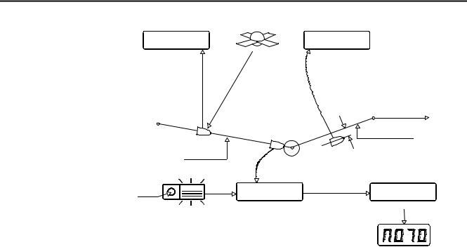
Steering by bearing to waypoint (CTS)
For some navigational receivers, bearing to a waypoint or course to steer is used as the steering information.
If a satellite navigator is used, it should have compass and log input to ensure proper dead reckoning between each fix.
1.Set the navigation receiver to calculate bearing to a waypoint from present position.
2.Select AUTO-mode on the AP45, and set the course selector knob to the bearing showed on the navigation receiver.
3.Select NAV-mode. The output signals from the navigation receiver will correct the course to steer to make the vessel steer towards the waypoint.
The Information display shows time since last update and the amount of course change in degrees, while the course display shows the new course to steer.
08 MIN CHG:05° NAVIGATION
1.If the corrections from the navigation receiver initiates a course change greater than 10 degrees, the autopilot alarm is activated and the course change has to be acknowledged using the ALARM RESET button.
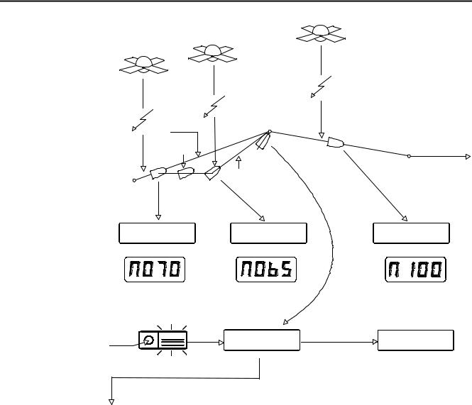
A typical sailing situation is illustrated in figure below.
Simrad Robertson AS
Egersund - Norway
Robertson AP45 Autopilot |
Page 2-9 |
Operation |
|
|
Transit satellites |
|
|
|
|
Update |
HDG=70° |
Update |
WAYPOINT2 |
|
|
|
|
|||
Update |
|
|
|
Heading: 100° |
Drift |
|
|
|
|
|
|
|
|
|
|
|
|
|
WAYPOINT 3 |
|
|
NEW HDG 65° |
|
|
WAYPOINT 1 |
|
|
|
|
08MINCHG 00° |
|
00MINCHG 05° |
15MINCHG 00° |
|
NAVIGATION |
|
|
NAVIGATION |
NAVIGATION |
INFO DISPLAY |
|
|
INFODISPLAY |
INFO DISPLAY |
COURSE DISPLAY |
|
|
COURSE DISPLAY |
COURSE DISPLAY |
ALARM
RESET
ACCEPT CHANGE? |
RESET |
15MINCHG 00° |
Y: RESET N: AUTO |
|
NAVIGATION |
INFO DISPLAY
Waypoint 2 has been reached. Continue as follows:
•If the heading to next waypoint, showed on the heading display, is accepted, press RESET.
If not, press AUTOPILOT mode and continue without Nav. Steering
By pressing RESET, the new heading is automatically entered and the autopilot will turn the vessel towards the new heading.
When reaching waypoint 3, repeat the same procedure.
Simrad Robertson AS
Egersund - Norway
Page 2-10 |
Robertson AP45 Autopilot |
|
Operation |
Remote Controls
General
F200-40 Remote
Control
The different types of Remote Controls that can be connected to AP45, have different way of operation, depending on the system configuration.
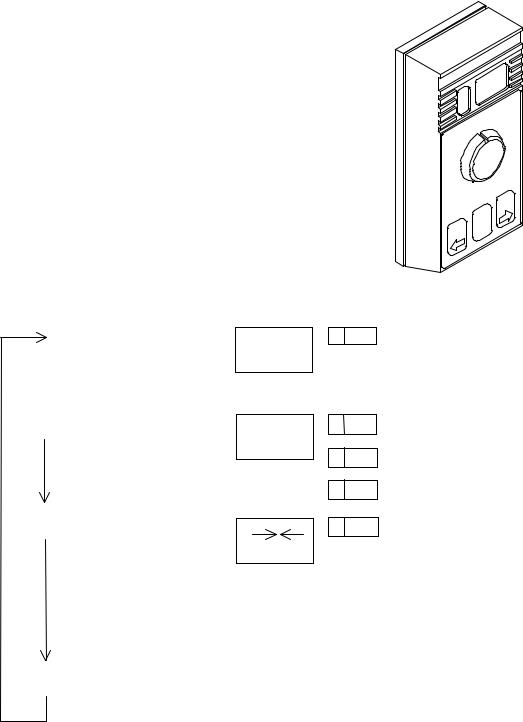
The F200-40 hand held remote control makes it possible to remotely control the AP45 autopilot.
The following control functions are obtainable:
•Display that shows vessel heading or set course like the course display on the control unit.
•Course selection by a rotating knob
•Course adjustments by push buttons
•Mode selection
•Manual steering by course selector knob (Follow-Up)
•Manual steering by push buttons (Non-Follow-Up) Option (selected during installation or sea trial):
•Dodging by means of course selector knob and automatic return to previous set course.
F200-40 without dodging
Press |
AP45 |
Function |
AP45 |
|
F200 Display |
|
|
Mode |
|
Display |
|
|
|
|
MANUAL |
NFU |
NON |
H 080 |
|
Vessel’s heading |
|
|
steering by |
FOLLOW UP |
|
|
|
|
|
MANUAL |
|
|
|
|
|
|
F200 |
|
|
|
|
|
|
|
|
|
|
|
|
|
PORT/STBD |
|
|
|
|
|
|
push buttons |
|
|
|
|
MODE |
MANUAL |
Follow-Up |
F200 |
F ¯ 00 |
|
Amidships, no |
|
|
steering by |
FOLLOW UP |
|
|
rudder command |
|
|
MANUAL |
|
|
||
|
|
F200 course |
F 04 |
|
4° port rudder |
|
|
|
|
|
|||
|
|
selector |
|
F 32 |
|
command |
|
|
|
|
|
32° starboard rudder |
|
|
|
|
|
|
|
command |
MODE |
AUTO |
Autosteering |
|
A 146 |
|
Set course |
|
|
Course set |
AUTO |
|
|
|
|
|
by the |
|
|
|
|
|
|
AP45/F200 |
|
|
|
|
|
|
course |
|
|
|
|
|
|
selector or |
|
|
|
|
|
|
PORT/ STBD |
|
|
|
|
|
|
button on |
|
|
|
|
|
|
both |
|
|
|
|
MODE |
|
|
|
|
|
|
|
|
|
|
|
|
|
Simrad Robertson AS
Egersund - Norway
Robertson AP45 Autopilot |
|
|
|
|
Page 2-11 |
|
|
Operation |
|
|
|
|
|
|
|
|
F200-40 with dodging |
|
|
|
|
||
|
Press |
AP45 |
Function |
AP45 Display |
F200 Display |
|
|
|
|
Mode |
|
|
|
|
|
|
|
MANUAL |
NFU |
NON FOLLOW UP |
H 080 |
Vessel’s heading |
|
|
|
|
steering by |
|
|
|
|
|
|
|
MANUAL |
|
|
|
|
|
|
|
F200 |
|
|
|
|
|
|
|
PORT/STBD |
|
|
|
|
|
|
|
push |
|
|
|
|
|
|
|
buttons |
|
|
|
|
|
MODE |
MANUAL |
Follow-Up |
F200 FOLLOW UP |
F ¯00 |
Amidships, no |
|
|
|
|
steering by |
|
rudder command |
|
|
|
|
|
MANUAL |
|
|
||
|
|
|
F200 course |
|
|
4° port rudder |
|
|
|
|
selector |
|
F 04 |
command |
|
|
|
|
|
|
F 32 |
32° starboard |
|
|
|
|
|
|
rudder command |
|
|
|
MODE |
AUTO |
Autosteering |
|
A 146 |
Set course |
|
|
|
|
Course set |
AUTO |
|
|
|
|
|
|
by the |
|
|
|
|
|
|
|
AP45/F200 |
|
|
|
|
|
|
|
course |
|
|
|
|
|
|
|
selector or |
|
|
|
|
|
|
|
PORT/ |
|
|
|
|
|
|
|
STBD |
|
|
|
|
|
|
|
button on |
|
|
|
|
|
|
|
both |
|
|
|
|
|
MODE |
Returns |
|
|
|
|
|
|
long |
to |
|
|
|
|
|
|
press |
MANUAL |
|
|
|
|
|
|
|
|
|
|
|
|
|
|
MODE |
AUTO |
DODGING |
* * * * * * * |
F ¯00 |
Amidships, no |
|
|
short |
|
made by the |
|
rudder command |
|
|
|
|
DODGING |
|
|
|||
|
press |
|
F200 course |
|
4° port rudder |
|
|
|
|
|
|
|
|||
|
|
|
|
|
|
||
|
|
|
selector |
|
F 04 |
command |
|
|
|
|
|
|
F 32 |
32° starboard |
|
|
|
|
|
|
rudder command |
|
|
|
MODE |
|
Returns to |
|
|
|
|
|
|
|
previous set |
|
|
|
|
|
|
|
course |
|
|
|
|
S9 Steering Lever The S9 steering lever is intended for use together with e.g. AP45 Autopilot. Several units can be connected in parallel, but only if configured as alternative 1 (see next page)
Operation
Activation is achieved by pulling out the lever. The lever is spring loaded to mid position, and can be used for starboard or port rudder commands. After finishing the manoeuvres the lever will be locked when pushed back to non-operational position.
Simrad Robertson AS
Egersund - Norway

Page 2-12 |
Robertson AP45 Autopilot |
|
Operation |
Alternative operation.
The S9 can be configured in four alternatives. At delivery from Robertson the S9 is connected for alternative 1. If alternative 2, 3 or 4 is to be used, S9 has to be modified according to the chapter “S9 Steering Lever”, page 5-26.
Note!
If a F200-40 also is connected, only alternative 1 can be used.
Alternative 1 (No resistor) |
|
|
|
|
|
|
|
|
|
S9 Lever |
AP45 Mode |
Function |
|
AP45 Displays |
|
|
|||
IN |
MANUAL |
S9 locked |
|
NON FOLLOW UP |
|
|
H 080 |
||
|
|
|
|
MANUAL |
|
|
|
|
|
|
|
|
|
|
|
|
|
|
|
OUT |
MANUAL |
NFU steering by |
|
NON FOLLOW UP |
|
|
H 080 |
|
|
|
|
moving lever to |
|
MANUAL |
|
|
|
|
|
|
|
left or right |
|
|
|
|
|
|
|
IN |
AUTO, |
S9 locked |
|
|
|
|
|
A 146 |
|
|
WORK |
|
|
AUTOMATIC |
|
|
|
|
|
OUT |
AUTO, |
Course change |
|
|
|
|
|
A 146 |
|
|
WORK |
by moving lever |
|
AUTOMATIC |
|
|
|
|
|
|
|
|
|
|
|
|
|
|
|
Alternative 2 (R = 1K) |
|
|
|
|
|
|
|
|
|
S9 Lever |
AP45 Mode |
Function |
|
AP45 Displays |
|
|
|||
IN |
MANUAL |
S9 locked |
|
NON FOLLOW UP |
|
|
H 080 |
||
|
|
|
|
MANUAL |
|
|
|
|
|
|
|
|
|
|
|
|
|
|
|
OUT |
MANUAL |
NFU steering by |
|
NON FOLLOW UP |
|
|
|
H 080 |
|
|
|
moving lever to |
|
MANUAL |
|
|
|
|
|
|
|
left or right |
|
|
|
|
|
|
|
|
|
|
|
|
|
|
|
|
|
IN |
AUTO, |
S9 locked |
|
|
|
|
|
A 146 |
|
|
|
|
|
|
|||||
|
WORK |
|
|
AUTOMATIC |
|
|
|
|
|
|
|
|
|
|
|
|
|
|
|
|
|
|
|
|
|
|
|
|
|
OUT |
AUTO, |
Dodging made by |
|
DODGING |
|
|
|
H 080 |
|
|
WORK |
lever |
|
|
|
|
|
|
|
IN |
AUTO, |
S9 locked. |
|
|
|
|
|
A 146 |
|
|
|
|
|
|
|||||
|
WORK |
Return to |
|
AUTOMATIC |
|
|
|
|
|
|
|
previous course |
|
|
|
|
|
|
|
Simrad Robertson AS
Egersund - Norway

Robertson AP45 Autopilot |
|
|
|
|
|
Page 2-13 |
|
|||||
Operation |
|
|
|
|
|
|
|
|
|
|
|
|
|
Alternative 3 (R = 3K) |
|
|
|
|
|
|
|
|
|
|
|
|
S9 Lever |
AP45 Mode |
Function |
|
AP45 Displays |
|
|
|
||||
|
IN |
MANUAL |
S9 locked |
|
NON FOLLOW UP |
|
|
H 080 |
|
|||
|
|
|
|
|
MANUAL |
|
|
|
|
|
||
|
|
|
|
|
|
|
|
|
|
|
|
|
|
OUT |
MANUAL |
NFU steering by |
|
NON FOLLOW UP |
|
|
H 080 |
|
|
||
|
|
|
moving lever to |
|
MANUAL |
|
|
|
|
|
||
|
|
|
left or right |
|
|
|
|
|
|
|
|
|
|
IN |
AUTO, |
S9 locked |
|
|
|
|
|
|
A 146 |
|
|
|
|
|
|
|
|
|
|
|||||
|
|
WORK |
|
|
AUTOMATIC |
|
|
|
|
|
|
|
|
|
|
|
|
|
|
|
|
|
|
|
|
|
OUT |
MANUAL |
NFU-steering by |
|
NON FOLLOW UP |
|
|
H 080 |
|
|||
|
|
|
moving lever |
|
MANUAL |
|
|
|
|
|
||
|
IN |
MANUAL |
S9 locked. |
|
NON FOLLOW UP |
|
|
H 080 |
|
|||
|
|
Remains in |
Return to |
|
MANUAL |
|
|
|
|
|
||
|
|
manual mode |
previous course |
|
|
|
|
|
|
|
|
|
|
|
until new mode |
|
|
|
|
|
|
|
|
|
|
|
|
|
|
|
|
|
|
|
|
|
|
|
|
|
has been selected |
|
|
|
|
|
|
|
|
|
|
|
|
on control unit. |
|
|
|
|
|
|
|
|
|
|
|
Alternative 4 (R = 5,1K) |
|
|
|
|
|
|
|
|
|
|
|
|
S9 Lever |
AP45 Mode |
Function |
|
AP45 Displays |
|
|
|
||||
|
IN |
MANUAL |
S9 locked |
|
|
|
|
|
|
H 080 |
|
|
|
|
NON FOLLOW UP |
|
|
|
|
|
|||||
|
|
|
|
|
MANUAL |
|
|
|
|
|
|
|
|
|
|
|
|
|
|
|
|
|
|
|
|
|
OUT |
MANUAL |
NFU steering by |
|
NON FOLLOW UP |
|
|
H 080 |
|
|||
|
|
|
moving lever to |
|
MANUAL |
|
|
|
|
|
||
|
|
|
left or right |
|
|
|
|
|
|
|
|
|
|
IN |
AUTO, |
S9 locked |
|
|
|
|
|
|
A 146 |
|
|
|
|
WORK |
|
|
AUTOMATIC |
|
|
|
|
|
||
|
OUT |
MANUAL |
NFU-steering by |
|
NON FOLLOW UP |
|
|
H 080 |
|
|||
|
|
|
moving lever |
|
MANUAL |
|
|
|
|
|
||
|
IN |
AUTO, |
S9 locked. |
|
|
|
|
|
|
A 080 |
|
|
|
|
AUTOMATIC |
|
|
|
|
||||||
|
|
WORK |
Continues on |
|
|
|
|
|
|
|
||
|
|
|
new set course, |
|
|
|
|
|
|
|
|
|
|
|
|
|
|
|
|
|
|
|
|
|
|
|
|
|
same as vessel’s |
|
|
|
|
|
|
|
|
|
|
|
|
heading |
|
|
|
|
|
|
|
|
|
Simrad Robertson AS
Egersund - Norway
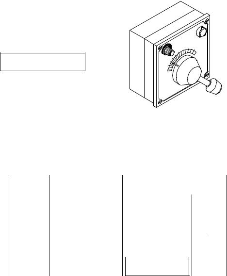
Page 2-14 |
Robertson AP45 Autopilot |
|
Operation |
FU91 Follow up Steering Lever
Operation
The FU91 is activated by operating the push to take command (PTTC) button. When in “COMMAND”, the button light is switched on and the autopilot INFO display will show:
FOLLOW UP
HELMSMAN
Rudder commands are made by setting the lever to the required rudder angle, wherafter the rudder will move to the commanded angle and stop.
FU91 may be connected to AP45 in two different ways. See Fig. 5-32 and Fig. 5-33
FU91 without mode switching
The lever can only be activated when the autopilot is in Helmsman mode. Pressing the PTTC button repeatedly will toggle between NFU and FU mode on AP45. See table below.
FU91 |
AP45 |
Function |
AP45 Displays |
|
|
|
||
Switch |
Mode |
|
|
|
|
|
|
|
|
|
|
|
|
|
|
|
|
OFF |
MANUAL |
NFU steering by NFU |
NON FOLLOW UP |
|
|
H |
085 |
|
|
|
lever or push button |
MANUAL |
|
|
|
|
|
|
|
control |
|
|
|
|
|
|
|
|
|
|
|
|
|
|
|
|
|
|
|
|
|
|
|
|
ON |
MANUAL |
Follow Up steering by |
FOLLOW UP |
|
|
H |
085 |
|
|
|
moving FU91 lever to |
MANUAL |
|
|
|
|
|
|
|
|
|
|
|
|
||
|
|
desired rudder angle |
|
|
|
|
|
|
|
|
|
|
|
|
|
|
|
|
|
as read on FU91 |
|
|
|
|
|
|
ON-OFF |
AUTO |
Automatic steering |
* * * * * |
|
|
|
|
|
|
|
A 080 |
|
|||||
|
|
|
AUTO |
|
|
|
|
|
|
|
|
|
|
|
|
||
Note!
If the Helmsman button is pressed when the FU91 is active, or if a NFU lever is operated, the autopilot will go to NFU mode even though the PTTC button light is on. However, as soon as the FU91 is operated again (lever is moved), the autopilot will resume FU mode.
For safety reason, the FU91 should always be switched to OFF when not in use.
FU91 with mode switching
The lever can be activated also with autopilot in Auto mode. Pressing the PTTC button brings the AP45 into Helmsman mode. What mode/sequence you get when pressing the PTTC button again is depending on which value of the resistor R is installed (Ref. page 5-29)
R = 1K: Auto - Dodge - Auto (previous course) R = 3K: Auto Manual - Manual
R = 5,1K: Auto - Manual - Auto (new course)
The mode change sequence is in principle similar to S9 operation alt. 2, 3 and 4 explained at page 2-12 and 2-13.
Simrad Robertson AS
Egersund - Norway
Robertson AP45 Autopilot |
Page 2-15 |
Operation |
|
Multiple FU91 installation
The operation of each lever is identical to above description of a single lever. Activating one FU91 will deactivate the one that was previously active.
FU91 and S9 connected to the same autopilot
It is recommended not to have both S9 and FU91 in operational condition at the same time. This may create confusion and inadvertent operation. The main rules are:
•Always put the S9 lever to locked position after use .
•Always switch the FU91 to OFF after use.
Simrad Robertson AS
Egersund - Norway

Page 2-16 |
|
|
Robertson AP45 Autopilot |
|
|
|
Operation |
Fault warnings |
The following fault warnings may be shown on the Information Display: |
||
|
|
OFF COURSE |
|
|
|
RESET ALARM |
|
|
Course deviation is greater than selected off course alarm limit. Press the Alarm |
||
|
button to cancel the alarm. The alarm is automatically reset when the vessel is |
||
|
back within the limit. |
|
|
|
|
RUDDER FEEDBACK |
|
|
|
FAIL! |
|
|
Indicates that the autopilot is not reading rudder feedback signal. By pressing the |
||
|
alarm reset button, the audible alarm will be reset and the autopilot will switch to |
||
|
a simulated signal, instead of the real. This is indicated by a flashing * * SIM * * |
||
|
on the information display. Repair actions should be taken when back in port. |
||
|
|
NO RESPONSE |
|
|
|
FROM RUDDER |
|
|
If a rudder command is not executed, or the rudder moves in wrong direction, this |
||
|
message will be shown on the display. The reason can be a malfunction of the |
||
|
steering gear, or simply that the steering gear is not switched on. |
||
|
|
NAVDATA NOT REC. |
|
|
|
CHANGE MODE |
|
|
Check that the nav. receiver is turned on and set up properly (see nav. receiver |
||
|
manual). |
|
|
|
|
POOR NAVDATA |
|
|
|
CHANGE MODE |
|
|
Poor reception conditions or improper set-up of nav. receiver. |
||
|
|
WRONG DATAFORMAT |
|
|
|
NAVRECEIVER |
|
|
Wrong NMEA-format selected on autopilot or transmitted by nav. receiver. |
||
|
MAGN.COMP.FAIL |
FLUXGATE FAIL |
GYROCOMPASS FAIL |
|
SELECT SENS.TYPE |
SELECT SENS.TYPE |
SELECT SENS.TYPE |
All three messages indicate problems with reading the signals from the navigation receiver. If you are unable to cure the problem, the NAV-mode should not be used before a Robertson dealer has been consulted.
These alarms will be given when the autopilot is unable to detect a proper signal from the selected heading sensor. The reason can be a faulty sensor or wrong selection of sensor (See “Type of Heading Sensor”, page 6-4).
DATA FAILURE
CHECK SETTINGS
If the autopilot should lose or read erratic data stored in the memory, this alarm will be given, and the autopilot is simultaneously set to MANUAL-mode.
Simrad Robertson AS
Egersund - Norway
Loading...