


 Loading...
INSTRUCTION MANUAL
Simrad HS50
Heading Sensor

Note!
Simrad AS makes every effort to ensure that the information contained within this document is correct. However, our equipment is continuously being improved and updated, so we cannot assume liability for any errors which may occur.
Warning!
The equipment to which this manual applies must only be used for the purpose for which it was designed. Improper use or maintenance may cause damage to the equipment or injury to personnel. The user must be familiar with the contents of the appropriate manuals before attempting to operate or work on the equipment.
Simrad AS disclaims any responsibility for damage or injury caused by improper installation, use or maintenance of the equipment.
Copyright
© 2002 Simrad AS
The information contained within this document remains the sole property of Simrad AS.
No part of this document may be copied or reproduced in any form or by any means, and the information contained within is not to be communicated to a third party, without the prior written consent of Simrad AS.

INSTRUCTION MANUAL
Instruction Manual
HS50 Heading Sensor
This manual is intended as a reference guide for installing, operating and maintaining Simrad HS50 Heading Sensor.
20221081 / F |
i |
Simrad HS50 Heading Sensor
Document revisions
Rev |
Date |
Written by |
Checked by |
Approved by |
|
|
|
|
|
A |
12.06.02 |
FOS/ |
|
|
|
|
|
|
|
B |
26.09.02 |
|
|
|
|
|
|
|
|
C |
06.11.02 |
|
|
|
|
|
|
|
|
D |
02.04.03 |
FOS/ |
|
|
|
|
|
|
|
E |
06.11.03 |
FOS/ |
|
|
|
|
|
|
|
F |
07.01.04 |
|
|
|
|
|
|
|
|
Document history
Rev. A Original issue.
Rev. B The manual updated and rewritten.
Rev. C Cable pair numbers for Sensor unit corrected (page 13). Optional documentation for additional languages added.
Rev. D Updated to correspond with PU sw version 2.02.03 and DU sw version 1.02.
Rev. E Updated to correspond with PU sw version 2.02.04, DU sw version 1.03. and SU sw version 1.02 . Dim. drawing for Sensor unit updated to show mounting direction.
Rev.F Corrected part number for HS50 Display unit mounting bracket (page 16).
To assist us in making improvements to this manual, we would welcome comments and constructive criticism. Please send all such - in writing to:
Simrad Egersund AS
Nyåskaien
P.O. Box 55
N-4379 Egersund, Norway
or by e-mail to: simrad.documentation@simrad.com
ii |
20221081 / F |

INSTRUCTION MANUAL
Contents
1. INTRODUCTION ................................................................ |
1 |
|
1.1 |
HS50 System components............................................. |
1 |
1.2 |
About this manual ........................................................ |
3 |
1.3 |
Definitions, abbreviations and acronyms.......................... |
3 |
|
Definitions ....................................................................... |
3 |
|
Abbreviations and acronyms............................................... |
4 |
2. TECHNICAL SPECIFICATIONS ........................................... |
5 |
|
2.1 |
Health, environment and safety ..................................... |
5 |
2.2 |
Restrictions in guarantee............................................... |
5 |
2.3 |
Restrictions in use ........................................................ |
5 |
2.4 |
Performance data......................................................... |
6 |
2.5 |
Physical dimensions...................................................... |
6 |
|
Sensor unit ...................................................................... |
6 |
|
Display unit ..................................................................... |
6 |
|
Processing unit ................................................................. |
7 |
2.6 |
Power......................................................................... |
7 |
|
Processing unit ................................................................. |
7 |
2.7 |
Environmental specification ........................................... |
7 |
|
Sensor unit ...................................................................... |
7 |
|
Display unit ..................................................................... |
7 |
|
Processing unit ................................................................. |
8 |
2.8 |
Cable ......................................................................... |
8 |
|
Processing unit to sensor unit cable ..................................... |
8 |
2.9 |
Interface..................................................................... |
8 |
3. INSTALLATION.................................................................. |
9 |
|
3.1 |
General ...................................................................... |
9 |
3.2 |
Cable connection.......................................................... |
9 |
3.3 |
Grounding................................................................... |
9 |
3.4 |
Sensor unit ................................................................ |
10 |
|
Location of the unit ......................................................... |
10 |
|
Mechanical installation..................................................... |
11 |
20221081 / F |
iii |

Simrad HS50 Heading Sensor
|
|
Cable wiring................................................................... |
13 |
|
|
Waterproofing the connectors ........................................... |
14 |
|
3.5 |
Display unit................................................................ |
14 |
|
|
Location of the unit ......................................................... |
14 |
|
|
Panel mounting .............................................................. |
15 |
|
|
Bracket mounting (option) ............................................... |
16 |
|
|
Display unit cable ........................................................... |
17 |
|
3.6 |
Processing unit ........................................................... |
18 |
|
|
Cable connections ........................................................... |
19 |
|
|
Connecting to Simrad equipment ...................................... |
21 |
|
3.7 |
Software setup procedure............................................. |
24 |
|
|
Display Adjustments........................................................ |
25 |
|
|
Differential corrections..................................................... |
26 |
|
|
Data output ................................................................... |
27 |
|
|
Ethernet ........................................................................ |
28 |
|
|
General ......................................................................... |
28 |
|
|
Expert setup .................................................................. |
30 |
4. |
OPERATING INSTRUCTIONS ........................................... |
33 |
|
|
4.1 |
Overview ................................................................... |
33 |
|
4.2 |
Turning the system ON/OFF.......................................... |
34 |
|
4.3 |
Performance monitoring ............................................... |
34 |
|
|
Navigation/HDT display ................................................... |
36 |
|
|
Navigation/POS display.................................................... |
36 |
|
|
Info displays .................................................................. |
37 |
|
4.4 |
Alarms....................................................................... |
39 |
|
|
Invalid Position alarm ...................................................... |
40 |
|
|
Invalid Heading alarm ..................................................... |
40 |
|
|
Invalid Position and Heading alarm.................................... |
40 |
|
4.5 |
Operation................................................................... |
41 |
|
|
Height aided GPS position ................................................ |
41 |
5. |
MAINTENANCE ................................................................ |
43 |
|
|
5.1 |
General ..................................................................... |
43 |
|
5.2 |
Periodic maintenance................................................... |
43 |
|
|
Sensor unit .................................................................... |
43 |
iv |
20221081 / F |
|
|
|
INSTRUCTION MANUAL |
|
|
Processing unit ............................................................... |
44 |
|
|
Display unit ................................................................... |
44 |
|
|
Software upgrades.......................................................... |
44 |
|
5.3 |
Repairs and modifications............................................. |
45 |
|
|
Replacing damaged cables ............................................... |
45 |
|
|
Replacing damaged units ................................................. |
45 |
|
5.4 |
Troubleshooting .......................................................... |
45 |
|
|
No response................................................................... |
46 |
|
|
No valid data.................................................................. |
46 |
|
|
No Differential corrections ................................................ |
47 |
|
|
Invalid Heading .............................................................. |
47 |
|
|
Reduced heading indication .............................................. |
48 |
|
|
Simulated data ............................................................... |
48 |
6. |
FIGURES AND DRAWINGS............................................... |
49 |
|
|
6.1 |
Sensor unit, dimensions ............................................... |
50 |
|
6.2 |
Sensor unit bracket, dimensions.................................... |
51 |
|
6.3 |
Sensor unit pedestal, dimensions .................................. |
52 |
|
6.4 |
Processing unit, dimensions.......................................... |
53 |
|
6.5 |
Display unit, dimensions .............................................. |
54 |
7. |
PARTS LIST ..................................................................... |
55 |
|
|
7.1 |
Standard delivery........................................................ |
55 |
|
7.2 |
Optional equipment ..................................................... |
55 |
|
7.3 |
Documentation ........................................................... |
55 |
20221081 / F |
v |

Simrad HS50 Heading Sensor
THIS PAGE INTENTIALLY LEFT
BLANK
vi |
20221081 / F |
INTRODUCTION
1. INTRODUCTION
1.1HS50 System components
Simrad HS50 is a GPS compass that provides true heading output with position, velocity and rate of turn information in addition. This product replaces several vessel instruments with one compact navigation package: gyrocompass, GPS system, speed log and Rate Of Turn (ROT) indicator.
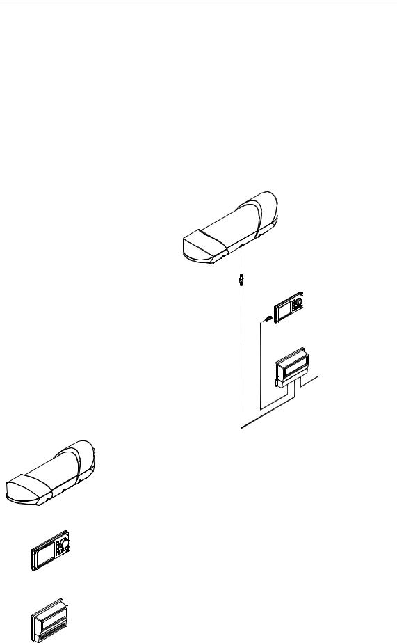
The HS50 comprises the following units:
SENSOR UNIT
1m
DISPLAY UNIT
30m
15m
PROCESSING
UNIT
POWER INPUT
The Sensor unit contains two GPS sensors, electronic board with I/O and an inertial rate element.
The Sensor unit is to be mounted in the vessel’s mast or flat on a roof or deck.
The Display unit contains an LCD for navigation information, mainboard with CPU, flash, power and I/O, and buttons for setup and operation of the HS50 system.
The Processing unit contains the mainboard with CPU, flash, power, I/O and a terminal list.
20221081 / F |
1 |

Simrad HS50 Heading Sensor
High-precision heading is derived from the fixed-distance dual GPS antenna arrangement in the Sensor unit, using carrier phase data to generate heading information independent of latitude and vessel dynamics. GPS position and speed are calculated from both antennas, which give redundant position and velocity sources in this product. DGPS signals may be input to the HS50 to improve position and velocity accuracy, but has no impact on the heading accuracy. Refer Performance data, page 6.
The inertial rate element provides yaw/ROT information. In case of short GPS outages, the inertial sensor automatically takes over as the prime source for heading determination until the GPS comes back on line. Working together seamlessly, the inertial and GPS elements of the system insure accurate, continuous and robust heading information.
The Processing unit includes configurable output serial lines (three RS-232 and three RS-422) and Ethernet connections making it easy to distribute HS50 data to multiple users on board the vessel.
The HS50 requires no scheduled maintenance or re-calibration. The system offers flexible configuration of the output variables and interface setup, depending on the vessel and application. It is easy to operate, install and align.
The HS50 system has the following features:
•True heading anywhere on earth
•Replaces several instruments with one robust, integrated product
•Heading available in periods of GPS drop-outs
•20 Hz update rate on heading and rate of turn measurements
•80°/sec follow-up rate
•Three RS-232 and three RS-422 configurable output serial lines
•Output data on Ethernet
•Only one cable (no coax) between the mast unit and the Processing unit on the bridge
2 |
20221081 / F |
INTRODUCTION
1.2About this manual
|
This manual is intended as a reference guide for operating, |
|
installing and maintaining the HS50 Heading Sensor. Please |
|
take time to read this manual to get thorough understanding of |
|
the operation and system components. |
|
In this manual the following notations are used: |
Caution! |
Used to make the user aware of procedures and operational |
|
practice which, if not followed, may result in degraded |
|
performance or damage to the equipment. |
Note! |
Used to draw the user's attention to special features or behavior |
|
of the equipment. |
1.3Definitions, abbreviations and acronyms
Definitions
Alignment The process of adjusting the current internal navigation frame (sensor-frame) in the instrument to the true vessel body frame.
Heading The direction of the main axis (bow direction) of the vessel. This is opposed to course, which is the direction of the vessel motion.
Yaw A rotation about the vertical axis and is positive when turning eastward when the vehicle cruises in north direction. Normally yaw means the dynamic yaw motion.
20221081 / F |
3 |

Simrad HS50 Heading Sensor
|
Abbreviations and acronyms |
CEP |
Circular Error Probability |
COG |
Course Over Ground |
DGPS |
Differential GPS |
DU |
HS50 Display Unit |
EPE |
Estimated Position Error |
GPS |
Global Positioning System |
GSA |
A standard NMEA message including GPS satellite ID |
|
numbers, PDOP, HDOP and VDOP |
HDOP |
Horizontal Dilution Of Precision |
HGT |
GPS Antenna Height above the WGS-84 ellipsoid |
IEC |
International Electrotechnical Commission |
IMO |
International Maritime Organization |
I/O |
Input/Output |
NMEA |
National Marine Electronics Association. NMEA 0183 is a |
|
standard for interchange of information between navigation |
|
equipment |
PDOP |
Positional Dilution Of Precision. This is the sum of the VDOP |
|
and HDOP figure |
PSXN20 |
A proprietary NMEA message including position, height and |
|
heading quality information |
PU |
HS50 Processing Unit |
RFI |
Radio Frequency Interference |
RF |
Radio Frequency |
RMS |
Root Mean Square |
ROT |
Rate of Turn |
RRE |
Range Residual Error, a proprietary format |
RTCM |
Radio Technical Commission of Maritime Services |
SOG |
Speed over Ground |
SSB |
Single Side Band |
UTC |
Universal Time Co-ordinate. This is the official time in the |
|
world and has replaced GMT (Greenwich Mean Time) as the |
|
official time |
VDOP |
Vertical Dilution Of Precision |
VHF |
Very High Frequency |
WGS-84 |
World Geodetic System of 1984 |
4 |
20221081 / F |

TECHNICAL SPECIFICATIONS
2. TECHNICAL SPECIFICATIONS
2.1Health, environment and safety
Operation or troubleshooting of HS50 equipment will not imply any risk for high voltages, explosions or exposure to gas. The HS50 is type-approved according to IEC 950/EN60950 standards regarding product safety (low voltage), and IEC 945/EN60945 standards on electromagnetic compatibility (immunity/radiation) and vibration.
2.2Restrictions in guarantee
The liability of the manufacturer is limited to repair of the HS50 only, and excludes consequential damages such as customer's loss of profit or damage to other systems traceable back to HS50 malfunction. The warranty does not cover malfunctions of the HS50 resulting from the following conditions:
a)The customer has opened the Sensor unit
b)Over-voltage or incorrect power connection
c)The equipment has been exposed to extreme chock and vibrations
2.3Restrictions in use
Simrad HS50 is designed for use on board marine surface operated vessels with roll and pitch motions up to ±30°.
The HS50 function is based on GPS signals and requires free sight to the sky, minimum 4 visible satellites, PDOP value less than 6 and otherwise normal conditions to operate.
20221081 / F |
5 |

Simrad HS50 Heading Sensor
2.4 Performance data
Heading accuracy, static:............................................... |
0.3° RMS |
Heading accuracy, dynamic:.......................................... |
0.5° RMS |
Heading resolution:............................................................... |
0.01° |
Heading operational measurement range: .Roll/pitch within ±30°
Rate of turn accuracy: |
................................................. 0.5º/s + 5% |
|
Position accuracy:................................................... |
5 m 95% |
CEP |
Velocity accuracy: ............................................ |
0.1 m/s 95% |
CEP |
Follow-up rate:................................................................... |
80°/sec |
|
The performance figures are valid with a minimum of 4 visible satellites, HDOP less than 4, PDOP value less than 6, high quality DGPS corrections * and otherwise normal conditions. Excessive multipath, GPS signal obstructions or interference may reduce the performance.
The HS50 Sensor unit includes two 12 channels GPS receivers.
*Has no impact on heading accuracy.
2.5Physical dimensions
Sensor unit
Width ................................................................ |
850 mm (33.5 in.) |
Height: ................................................................ |
205 mm (8.1 in.) |
Depth: ............................................................... |
262 mm (10.3 in.) |
Weight: ................................................................. |
8 kg (17.6 lbs.) |
Color: ................................................................................... |
White |
Dimensional drawing........................................................ |
Page 50 |
Display unit
Width: ................................................................. |
220 mm (8.7 in.) |
Height: ................................................................ |
110 mm (4.3 in.) |
Depth: ................................................................... |
39 mm (1.5 in.) |
Weight: ................................................................ |
0.5 kg (1.1 lbs.) |
Color: ................................................................................... |
Black |
Dimensional drawing........................................................ |
Page 54 |
6 |
20221081 / F |
|
TECHNICAL SPECIFICATIONS |
Processing unit |
|
Width: ............................................................... |
287 mm (11.3 in.) |
Height: ................................................................... |
203 mm (8 in.) |
Depth: ................................................................... |
60 mm (2.4 in.) |
Weight: ................................................................ |
1.3 kg (2.9 lbs.) |
Color: ................................................................................... |
Black |
Dimensional drawing........................................................ |
Page 53 |
2.6Power
Processing unit
Voltage:.................................................................. |
10 to 36 V DC |
Power consumption: ............................................................. |
15 W |
2.7Environmental specification
Sensor unit
Enclosure material, sensor housing: |
.........................Polyethylene |
Enclosure material bracket: .......................... |
Anodized aluminum |
Enclosure protection:............................................................. |
IP65 |
Operating temperature range: ........... |
- 30 to +55ºC ( -22 to 131°F) |
Operating humidity (max.): ................................................. |
100% |
Storage temperature range: ............... |
- 30 to +70ºC ( -22 to 158°F) |
Storage humidity (max.): ..................................................... |
100% |
Safe distance to compass: ........................................ |
0.2 m (0.7 ft) |
Display unit
Enclosure protection:.............. |
IP-56 from front, IP-43 from back |
Operating temperature range: ................ |
0 to +55ºC (32 to 131°F) |
Storage temperature range: ............... |
-30 to +80ºC (-22 to 176°F) |
Safe distance to compass: ..................................... |
0.35 m (1.1 ft.) |
20221081 / F |
7 |

Simrad HS50 Heading Sensor
Processing unit
Enclosure material: ....................................... |
Anodized aluminum |
Enclosure protection:............................................................. |
IP44 |
Operating temperature range: ................ |
0 to +55ºC (32 to 131°F) |
Storage temperature range: ................. |
-20 to +60ºC (-4 to 140°F) |
Safe distance to compass: ........................................ |
0.2 m (0.7 ft) |
2.8 Cable |
|
Processing unit to sensor unit cable |
|
Type: ...................................................... |
2x2x0.5 mm2 with shield |
Maximum length:................................................... |
100 m (328 ft) |
Diameter: .............................................................. |
10 mm (0.4 in.) |
Flame retardation:..................................................... |
IEC 332-3/A |
2.9 Interface
Configuration:....... |
Display unit connected to the Processing unit |
|
Data outputs:........................................ |
Three RS-232 serial lines, |
|
|
Three RS-422 serial lines, |
|
|
|
Ethernet UDP/IP |
Data inputs:.................... |
One RS-232 and one RS-422 serial line |
|
DGPS corrections: ..... |
RTCM 104 version 2.2 and SAPOS® EPS |
|
Baud rate:........................................................... |
|
Max. 38.4 kBaud |
HDT, ROT, GGA and GLL data update rates: |
..........Up to 20 Hz |
|
HDT, ROT, GGA and GLL data delay:............... |
Less than 50 ms |
|
ZDA and VTG data update rate:.................................... |
Max 1 Hz |
|
VTG data delay:......................................................... |
|
Max 1.5 sec |
ZDA data delay:..................................................................... |
|
1 ms |
Data output formats:
•NMEA 0183 ZDA, GGA, GLL, VTG, HDT, ROT, GSA, GRS and proprietary messages PSXN,20. The PSXN,20 message include position, height and heading quality information
•RD Instrument ADCP proprietary NMEA format, "PRDID".
•Radar clock data
8 |
20221081 / F |
INSTALLATION
3. INSTALLATION
3.1General
The following parts are supplied with a standard HS50 system:
−Sensor unit with 1 meter cable w/connector and 4 fastening bolts
−Display unit with 15 meters cable to the Processing unit and flush mounting kit
−Processing unit including 4 fastening screws
−30 meters cable to be used between Sensor unit and Processing unit
−Documentation
Caution!
The Sensor unit has to be mounted in a way that avoids blocking of the GPS signal.
The Processing and Display Unit can be mounted on the bridge or in the instrument room.
No units should be exposed to heavy vibration, transformers or similar.
3.2Cable connection
Use only shielded cables for the installation. This includes power input and signal cables. The cables should be of 0.5 mm2 (AWG20) twisted pairs.
The cable to the Display unit and other cables (NMEA input/output, Ethernet) should not be run in parallel with other cables carrying RF or high current, such as VHF and SSB transmitters, battery charges/generators and winches.
3.3Grounding
All units in the HS50 system use the Processing unit as a common ground/shield connection. The Processing unit should therefore have a proper ground connection to the hull/bonding system.
20221081 / F |
9 |
Simrad HS50 Heading Sensor
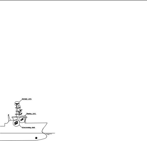
3.4Sensor unit
Location of the unit
The Sensor unit is the most important part of the HS50 system, and great care should be taken when deciding the mounting location.
The space above the Sensor unit has to be free of obstructions of any kind. A GPS compass is more sensitive for blocking and reflections (multipath) of GPS signals than GPS sensors that are only used for calculating position. This since HS50 also utilizes carrier phase measurements for heading determination, and both GPS antennas need to see at least two common satellites at the same time.
The unit should be protected from direct illumination of radar beams and other transmitting antennas such as Inmarsat antennas.
The Sensor unit has to be mounted horizontally in the mast or directly on deck, with 5° maximum allowed deviation angle from the horizontal plane. If mounted in the mast, the distance from the unit to the nearest deck should be as large as possible to reduce problem due to the multipath effect.
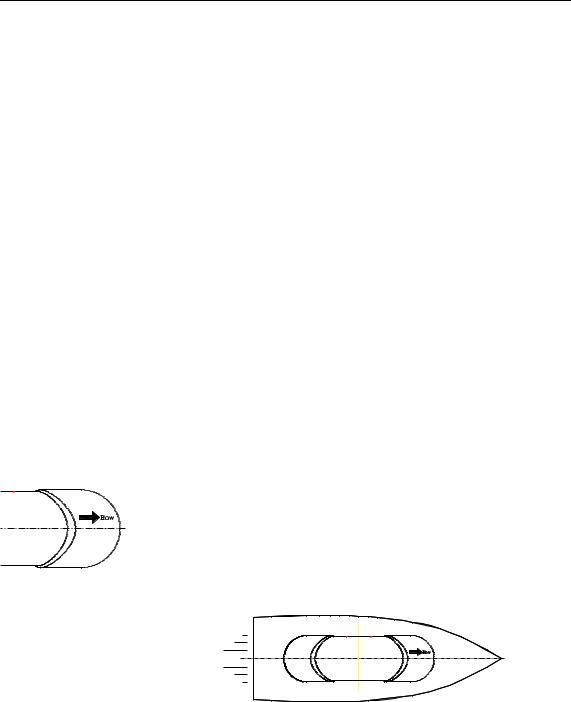
The unit should also be mounted parallel to the vessel’s centerline with the bow arrow pointing forward. The heading offset feature will however compensate for a heading offset caused by the orientation of the Sensor unit. An eventual offset correction is performed after the calibration as described in
Software setup procedure, Heading offset, page 31.
10 |
20221081 / F |
INSTALLATION
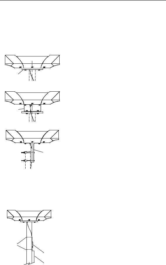
Mechanical installation
The Sensor unit may be mounted in the mast or directly on the deck.
The dimensional drawing for the Sensor unit on page 50 shows dimensions and internal distance for the mounting holes and the cable outlet.
If necessary, a user-made holder may be used as
shown on the figure when installing the unit.
Holder
Bracket
A mounting bracket (part no. 20213039) or a
mounting pedestal (part no 20213021) can be delivered from Simrad by request. Dimensions for these optional mounting devices are shown on page 51 and page 52.
Refer Bracket mounting (option), page 12, and
Pedestal mounting (option), page 13.
Pedestal
Caution!
Cable ties
Independent on which fastening method that is used, the Sensor unit should not differ more than ±5° from the vessel’s horizontal plane and the alongships axis. If the mounting is not within this tolerance, the heading accuracy will be degraded.
Connectors with self-bonding tape
Cable duct
Connect the cable from the Processing unit to the cable from the Sensor unit.
Caution!
The connector junction must be sealed with self-bonding tape for waterproofing. After coiling, make bonding by hard pressure.
Use the required number of cable ties to fasten the cable to the mast.
20221081 / F |
11 |
Loading...