


RS81/RS82 VHF
8 MENU MODE
Menu mode is used to adjust the various settings of the radio, such as channels inhibited from scan functions, MMSI number programming and User channel selection.
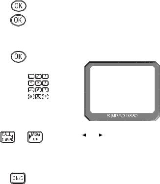
To enter Menu mode, press SHIFT followed by 9 (MENU).
Use the VOL ▲ and VOL ▼ keys to scroll through the menu options below:
•Scanning (section 8.1) – Options related to the various scanning functions such as channel inhibit, memory scan select and scan dwell time.
•Numbers (section 8.2) – Entering of ID numbers such as MMSI, Group MMSI and ATIS numbers (if applicable in country of use).
•VHF Items (section 8.3) – Miscellaneous options such as selection of User channel, last used channel, interrupt intercom, speaker settings and SimNet management.
|
To select an option, press OK. To return to normal radio opera- |
|
tion, press ON/C. |
NOTE |
Entering Menu mode will inhibit the operation of the radio. |
|
Exit Menu mode before returning the handset to the cradle to |
|
permit normal operation. |
8.1 Scanning
Once the Scanning menu option has been selected (see introduction to section 8), use the VOL ▲ and VOL ▼ keys to scroll through the menu options below:
• All scan inhibit |
(section 8.1.1) |
• All scan reset |
(section 8.1.2) |
• All scan show |
(section 8.1.3) |
• Memory scan select |
(section 8.1.4) |
• Memory scan clear |
(section 8.1.5) |
• Memory scan show |
(section 8.1.6) |
• Scan dwell time |
(section 8.1.7) |
To select an option, press OK. To return to the main menu, press ON/C.
8.1.1 All scan inhibit
If the radio is repeatedly locking onto a busy channel when scanning, this channel can be inhibited, i.e. excluded from the scan cycle.
52 |
E04572 |
Instruction manual
From the Scanning menu select “ALL SCAN INHIBIT” and press OK. Enter the relevant channel number using the numeric keypad. The display will show the channel number and its current status – “ALL SCAN” for enabled, or “ALL SCAN INHIBITED” for excluded channels (Fig 8.1). Use the OK key to change the channel’s status.
INT 65
ALL SCANAA
I NH I B I TEDB
Fig 8.1 - Selected channel inhibited from scan
Repeat the above procedure to enable or inhibit further channels, or use the VOL ▲ and VOL ▼ keys to select another menu option. To exit this menu level, press ON/C.
8.1.2 All
To reset all |
RESET” from |
the Scanning |
will show |
“CHANNELS |
|
CHANNELSSS
RESETEDBBB
Fig 8.2 - All inhibited channels reset
Use the VOL ▲ and VOL ▼ keys to select another option, or ON/C to return to the upper menu level.
8.1.3 All scan show
This function will display all inhibited channels. From the Scanning menu select “ALL SCAN SHOW” and press OK. The display will change to “SHOWING CHANNELS” and display all inhibited channels in sequence.
Press the VOL ▲ and VOL ▼ keys to select a further option, or ON/C to return to the main menu.
8.1.4 Memory scan select
This function selects the channels to be used in the Memory scan cycle (see section 7.9).
E04572 |
53 |
RS81/RS82 VHF
From the Scanning menu choose “MEM SCAN SELECT” and press OK. Enter the relevant channel number using the numeric keypad. The display will show the channel number and its memory status – “MEM SCAN” if it is not currently selected for memory scan, or “MEM SCAN ENABLED” if it is already selected (Fig 8.3).
INT |
65 |
INT 65 |
|
MEM SCANAA |
MEM SCANAA |
|
|
ENABLEDB B |
CHANNEL CURRENTLY NOT SELECTED |
CHANNEL ALREADY SELECTED |
|
|
Fig 8.3 - Selecting channel for Memory scan |
|
|
Use the OK key, to change the channel’s status – i.e. if it is not |
|
|
selected, pressing OK will add it to the Memory scan cycle and |
|
|
vice versa. |
|
|
Repeat the above procedure to select or deselect further chan- |
|
|
nels. When finished, press ON/C to return to the main menu, or |
|
|
use the VOL ▲ and VOL ▼ keys to select another menu option. |
|
NOTE |
North American users – Only one Weather channel can be |
|
|
stored in the memory scan; if another one is selected, it will |
|
|
override the existing channel. The Weather channel is not |
|
|
scanned as part of the memory scan sequence, it is in fact used |
|
|
by the Weather Watch function (see section 11.1). |
|
|
8.1.5 Memory scan clear |
|
|
Memory scan |
selected chan- |
|
nels. To clear |
CLEAR” from |
|
the Scanning |
will change to |
|
show “CHANNELS |
|
CHANNELSSS
CLEAREDBBB
Fig 8.4 - Clearing all previously selected channels
Press the VOL ▲ and VOL ▼ keys to select another Scanning menu option, or press ON/C to return to the main menu.
54 |
E04572 |
Instruction manual
8.1.6 Memory scan show
This function displays all channels selected for Memory scan. From the Scanning menu select “MEMORY SCAN SHOW” and press OK. The display will change to “SHOWING CHANNELS” and display all enabled channels in sequence.
Press the VOL ▼ or VOL ▲ key to select another Scanning menu option, or ON/C to return to the main menu.
8.1.7 Scan dwell time
This function is used to select the amount of time the RS82 remains on a channel, after it has locked onto it during a scanning function (All scan or Memory scan) and the signal is lost.
From the Scanning menu (section 8.1) select “SCAN DWELL TIME XX” (where “XX” denotes the current dwell time in seconds), then press OK (Fig 8.5).
|
|
SCAN DWELL |
|
|
|
T I ME |
04 |
|
|
Fig 8.5 - Scan dwell time |
|
|
The default time is “0”, meaning that the scan will continue as |
||
|
soon as the signal is lost. There are 11 levels from 0–10 seconds. |
||
|
Use the numeric keys to enter the scan dwell time and press OK |
||
|
to select – the display will show “DWELL TIME XX SECONDS”. |
||
|
Press the VOL ▲ or VOL ▼ key to select another Scanning menu |
||
|
option, or ON/C to return to the main menu. |
||
8.2 Numbers |
|
|
|
|
The Numbers menu is used for entering ID numbers such as |
||
|
MMSI, Group MMSI and ATIS (if applicable in country of use). |
||
|
Once the Numbers menu option has been selected (see intro- |
||
|
duction to section 8), the VOL ▲ and VOL ▼ keys to scroll |
||
|
through the menu options below: |
|
|
|
• Ship’s MMSI |
(section 8.2.1) |
|
|
• Group MMSI |
(section 8.2.2) |
|
|
• ATIS number |
(section 8.2.3) |
|
NOTE |
The ATIS number option will only be shown if the radio is |
||
|
ATIS enabled. This feature is only available for sets used in the |
||
|
Benelux and Rhine/Danube waterways. |
|
|
To return to the main menu, press ON/C.
E04572 |
55 |
RS81/RS82 VHF
|
|
|
|
|
|
8.2.1 Ship’s MMSI |
|
|
|
|
|
|
|
This function will display the boat’s MMSI (Maritime Mobile |
|
|
|
|
|
|
|
Service Identity) number, provided it has already been entered, |
|
|
|
|
|
|
|
or allow the MMSI to be entered if the radio is being used for |
|
|
|
|
|
|
|
the first time (cf. section 1.3). |
|
CAUTION |
|
|
The MMSI number can only be entered once and cannot be |
||||
|
|
|
|
|
|
edited by the user. Should it become necessary to change the |
|
|
|
|
|
|
|
MMSI number (for example, if the radio is being moved to |
|
|
|
|
|
|
|
another boat), the radio must be sent to an authorised Simrad |
|
|
|
|
|
|
|
service agent for reprogramming. |
|
|
|
|
|
|
|
From the Numbers menu (section 8.2) select “SHIPS MMSI” and |
|
|
|
|
|
|
|
press OK – the display will show the MMSI number, unless the |
|
|
|
|
|
|
|
number has not been entered yet, in which case it will show |
|
|
|
|
|
|
|
dashes only (Fig 8.6). To enter the MMSI number, press OK |
|
|
|
|
|
|
|
again. The display will show “ENTER MMSI” and the first |
|
|
|
|
|
|
|
dash will start flashing to indicate that entry can begin. |
|
|
|
|
|
|
|
INT |
16 |
|
|
|
|
|
|
|
SH I PS MMS Ii |
|
|
|
|
|
|
|
- - - - - - - - - |
|
|
|
|
|
|
Fig 8.6 - Entering the MMSI number |
|
|
|
|
|
|
|
Enter the nine-digit MMSI number using the numeric keypad |
|
|
|
|
|
|
|
and press OK. The radio will then ask the MMSI number be re- |
|
|
|
|
|
|
|
entered (“CONFIRM”). If the two numbers do not match, the |
|
|
|
|
|
|
|
procedure must be repeated. |
|
|
|
|
|
|
|
Use the CALL and |
MSG keys to move the cursor to correct |
|
|
|
|
|
|
any errors. The cursor position is indicated by the flashing |
|
|
|
|
|
||||
|
|
|
|
|
|
number. Enter a new number to overwrite an incorrect number. |
|
NOTE |
|
|
The MMSI number will not be accepted, unless all nine digits |
||||
have been entered.
Press ON/C to return to the main menu.
8.2.2 Group MMSI
For boats that are part of a flotilla, racing/fishing fleet or other group, a Group ID MMSI (Maritime Mobile Services Identity) number can also be entered and used to contact other boats in the same fleet (see also section 1.4).
56 |
E04572 |
|
|
|
|
|
|
|
|
|
Instruction manual |
NOTE |
|
|
|
The Group MMSI number may be allocated on a temporary |
|||||
|
|
|
|
|
|
|
|
basis by the local administration, for this reason the number |
|
|
|
|
|
|
|
|
|
can be changed by the user. |
|
|
|
|
|
|
|
|
|
From the Numbers menu (section 8.2) select “GROUP MMSI” |
|
|
|
|
|
|
|
|
|
and press OK – the display will show the Group MMSI, unless |
|
|
|
|
|
|
|
|
|
the number has not been entered yet (in which case it will show |
|
|
|
|
|
|
|
|
|
“_ _ _”). To enter the Group MMSI number press OK again. The |
|
|
|
|
|
|
|
|
|
display will change to show “ENTER MMSI” and the first dash |
|
|
|
|
|
|
|
|
|
in the number will start flashing to indicate that entry can begin. |
|
|
|
|
|
|
|
|
|
The first digit of a Group MMSI number is always “0” and this |
|
|
|
|
|
|
|
|
|
is pre-selected by the radio. Enter the remaining eight digits |
|
|
|
|
|
|
|
|
|
using the numeric keypad and press OK (Fig 8.7). |
|
|
|
|
|
|
|
|
|
INT |
16 |
|
|
|
|
|
|
|
|
|
GROUP MMS II |
|
|
|
|
|
|
|
|
|
0436 1 ---- |
|
|
|
|
|
|
|
|
Fig 8.7 - Entering a Group MMSI number |
|
|
|
|
|
|
|
|
|
Use the CALL and |
MSG keys to correct any errors. The |
|
|
|
|
|
|
|
|
cursor position is indicated by the flashing number. Enter a |
|
|
|
|
|
|
|
|
|
new number to overwrite an incorrect number. |
|
NOTE |
|
|
|
The number will not be accepted unless all eight remaining |
|||||
|
|
|
|
|
|
|
|
digits have been entered. |
|
|
|
|
|
|
|
|
|
Press ON/C to return to the main menu. |
|
|
|
|
|
|
|
|
|
8.2.3 ATIS number |
|
NOTE |
|
|
|
This section applies only to radios used in countries where the |
|||||
|
|
|
|
|
|
|
|
ATIS system is in operation (i.e. Benelux and the Rhine/Danube |
|
|
|
|
|
|
|
|
|
waterways). This option will only appear on ATIS-equipped |
|
|
|
|
|
|
|
|
|
radios. (Please refer to section 1.5 also.) |
|
CAUTION |
|
|
|
The ATIS number can only be entered once and cannot be edit- |
|||||
|
|
|
|
|
|
|
|
ed by the user. If it is necessary to change the ATIS number, the |
|
|
|
|
|
|
|
|
|
radio must be sent to an authorised Simrad service agent for |
|
|
|
|
|
|
|
|
|
reprogramming. |
|
From the Numbers menu (section 8.2) select “ATIS NO”; the display will show the ATIS number, unless the number has not been entered yet (in which case it will show “_ _ _”).
E04572 |
57 |
RS81/RS82 VHF
|
|
|
To enter the ATIS number press OK again. The display will now |
|
|
|
show “ENTER ATIS” and the first dash in the number will start |
|
|
|
flashing to indicate that entry can begin. |
|
|
|
Enter the nine-digit ATIS number using the numeric keypad |
|
|
|
and press OK. The radio will then ask the number be re-entered |
|
|
|
(“CONFIRM”). If the two numbers do not match, the proce- |
|
|
|
dure must be repeated. |
|
|
|
Use the CALL and MSG keys to move the cursor to correct |
|
|
|
any errors. The cursor position is indicated by the flashing |
|
|
|
|
|
|
|
number. Enter a new number to overwrite an incorrect number. |
NOTE |
The ATIS number will not be accepted, unless all nine digits |
||
|
|
|
have been entered - the prefix “9” is automatically inserted by |
|
|
|
the radio. |
|
|
|
Press ON/C to return to the main menu. |
8.3 VHF Items
The VHF Items menu contains the settings for miscellaneous functions such as User channel, position view, speaker settings, as well as SimNet management and lighting modes.
Once the VHF Items menu option has been selected (see introduction to section 8), use the VOL ▲ and VOL ▼ keys to scroll through the available menu options:
• User channel |
(section 8.3.1) |
• Position view |
(section 8.3.2) |
• Last used channel |
(section 8.3.3) |
• Interrupt intercom |
(section 8.3.4) |
• Speaker settings |
(section 8.3.5) |
• SimNet management |
(section 8.3.6) |
• Lighting modes |
(section 8.3.7) |
To select an option press OK. To return to the main menu press
ON/C.
8.3.1 User channel
This is a user-programmable priority channel that is used in the Tri-Watch function and can be selected by pressing the USER key.
From the VHF Items menu (section 8.3) select “USER CHAN-
NEL” and press OK. Using the numeric keypad enter the requi-
58 |
E04572 |

Instruction manual
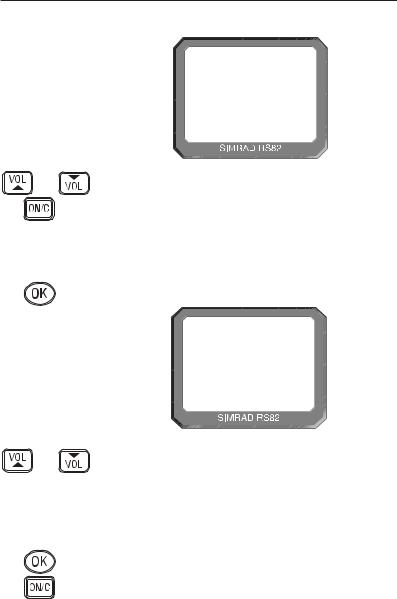
site channel number and press OK. The display will show “SET USER CHANNEL” (Fig 8.8).
INT 10
SET USERAA
CHANNELBBB
Fig 8.8 - Setting the User channel
Use the VOL ▲ and VOL ▼ keys to select another option, or press ON/C to return to the main menu.
8.3.2 Position view
This option allows the user to view the current GPS position that will be used if a distress call is made (Fig 8.9). The function of this option depends on whether the position is received automatically via NMEA, or has been entered manually.
INT
LAT
LON
16
89º 23. 000N 102º 54. 120E
Fig 8.9 - Position display
From the VHF Items menu (section 8.3) select “POSITION VIEW” and press OK. If GPS position information is being received, the display will show “POSITION VIEW OFF”. Use the OK key to toggle between “ON” and “OFF”.
When this option is turned on, the bottom two lines of the display will show the current “LAT/LON” positions on all handsets. If the volume or squelch is being adjusted, the display will show the settings while the VOL ▲ / VOL ▼ keys are operated, before reverting to the position display.
If no GPS position information is being received, the display will show “VIEW”. Pressing OK will show the position entered manually, or the last known GPS position. If no position has been entered, the “LAT/LON” display will show “9 9 9” only.
E04572 |
59 |
RS81/RS82 VHF
Use the VOL ▲ and VOL ▼ keys to toggle between position and time (UTC) displays.
Press ON/C to exit, or use the VOL ▲ and VOL ▼ keys to choose another option.
8.3.3 Last used channel
Normally the RS82 will power up on the pre-programmed start-up channel (usually the priority channel). This function enables the radio to power up on the last-used channel – the default setting is “OFF”.
From the VHF Items menu (section 8.3) select “LAST USED CHAN” and press OK – the current status will be displayed (“ON”/“OFF”). Use the OK key to toggle between the settings.
Press the VOL ▲ and VOL ▼ key to select another option, or
ON/C to return to the main menu.
8.3.4 Interrupt intercom
This function can be used to specify whether intercom functions should be interrupted when an incoming VHF transmission is received – the default setting is “Y” (“Yes”).
From the VHF Items menu (section 8.3) select “INTERRUPT INTERCOM” and press OK – the display will show the current status (“Y” or “N”). Use the OK key to toggle between settings.
Use the VOL ▲ and VOL ▼ keys to select another option, or
ON/C to return to the main menu.
|
8.3.5 Speaker settings |
|
The speaker settings option is used to set individual default |
|
volume levels for each station or intercom in the system. |
|
From the VHF Items menu (section 8.3) select “SPEAKER SET- |
|
TINGS” and press OK to enter the sub-menu. Use the VOL ▲ |
|
and VOL ▼ keys to scroll through each speaker, displaying the |
|
default volume level for each one. |
NOTE |
Only connected speakers will be shown. |
|
The first option in the sub-menu is “RESET TO DEFAULTS” |
|
(Fig 8.10, p. 61) – pressing OK will reset all speaker levels to |
|
their default settings, the display will show “RESETTING LEV- |
|
ELS”. To set the required volume levels for each individual |
|
position, use the VOL ▲ and VOL ▼ keys to select the required |
|
station and press OK. |
|
The selected speaker will emit a continuous tone indicating the |
|
current volume level. Press VOL ▲ and VOL ▼ to adjust the vol- |
|
ume level as desired and press OK to confirm. |
60 |
E04572 |
Instruction manual
|
INT |
16 |
|
|
RESET TO000 |
|
|
DEFAULTS00 |
|
Fig 8.10 - Resetting speaker settings to defaults |
|
|
Press the VOL ▲ and VOL ▼ keys to select another station and |
|
|
repeat the above procedure, or ON/C to return to the upper |
|
|
menu levels. |
|
|
8.3.6 SimNet management |
|
NOTE |
This option will only appear in the VHF Items menu, if the |
|
|
radio is operating on a SimNet bus. |
|
|
From the VHF Items menu select “SIMNET MANAGEMENT” |
|
|
and press OK (Fig 8.11). |
|
|
INT |
16 |
|
|
SIMNET |
|
|
MANAGEMENT |
Fig 8.11 - SimNet management page
Use the VOL ▲ and VOL ▼ keys to scroll through the available menus -
• Data sources |
(section 8.3.6.1) |
• Lighting banks |
(section 8.3.6.2) |
• Device instance |
(section 8.3.6.3) |
• System instance |
(section 8.3.6.4) |
To select an option, press OK.
To return to the VHF Items menu, press ON/C.
E04572 |
61 |
RS81/RS82 VHF
8.3.6.1 Data sources
This function is used to select the data source for position, date and time information, if the RS82 is part of a SimNet system with more than one unit providing nav data (Fig 8.12). It will only be shown if SimNet is present.
|
|
|
|
|
|
|
|
|
|
|
|
|
|
|
|
|
|
|
|
|
|
|
|
|
|
|
|
|
|
|
|
|
|
|
|
|
|
|
|
|
|
|
|
|
|
|
|
|
|
|
|
|
|
|
|
|
|
|
|
|
|
|
|
|
|
|
|
|
|
|
|
|
|
|
|
|
|
|
|
|
|
|
|
|
|
|
|
|
|
|
|
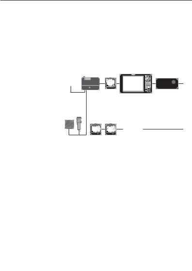
HS50 |
||
|
|
|
|
|
|
|
|
|
|
|
|
|
|
|
||||
|
|
|
|
|
|
|
|
CP44 Chartplotter |
|
Satellite Compass |
||||||||
|
|
|
|
|
|
|
|
|
||||||||||
|
|
|
|
|
|
|
|
|
||||||||||
|
|
|
|
|
|
|
|
|
|
|
|
|
||||||
|
|
|
|
|
|
|
|
|
|
|
|
|
||||||
|
Fig 8.12 - Example of multiple data sources on one SimNet system |
|||||||||||||||||
|
As a default, the RS82 will give priority to SimNet data over |
|||||||||||||||||
|
that received via the NMEA input. This function enables you to |
|||||||||||||||||
|
select the NMEA input as the priority data source. |
|||||||||||||||||
|
From the SimNet management menu select “DATA SOURCES” |
|||||||||||||||||
|
and press OK. |
|
|
|
|
|||||||||||||
|
Use the VOL ▲ and VOL ▼ keys to scroll through the following |
|||||||||||||||||
|
options - |
|
|
|
|
|||||||||||||
|
|
Simrad Group – (Default) Accept the data source aspecified |
||||||||||||||||
|
|
by the Group Owner. A Group Owner is a unit capable of dic- |
||||||||||||||||
|
|
tating which data source other SimNet units on the bus use. |
||||||||||||||||
|
|
The Group Owner is usually a Chartplotter or similar unit. |
||||||||||||||||
|
|
NMEA0183 – This option will select the NMEA0183 input as |
||||||||||||||||
|
|
the nav data source. |
|
|
|
|
||||||||||||
|
|
SimNet units – The display will show the name and serial |
||||||||||||||||
|
|
number of each SimNet unit detected on the network. |
||||||||||||||||
|
|
Third Party units – The display will show the name and ser- |
||||||||||||||||
|
|
ial number of any third party units connected to the bus via |
||||||||||||||||
|
|
NMEA2000. |
|
|
|
|
||||||||||||
NOTE |
Apart from NMEA0183, a maximum of four other sources |
|||||||||||||||||
|
will be shown, and these will be the first four detected. Any |
|||||||||||||||||
|
further sources apart from these will be ignored. |
|
|
|
|
|||||||||||||
|
Press OK to set the selected data source. The display will show |
|||||||||||||||||
|
“SOURCE SELECTED”, then exit to the SimNet management |
|||||||||||||||||
|
menu. |
|
|
|
|
|||||||||||||
NOTE |
If the selected data source is lost, the radio will automatically |
|||||||||||||||||
|
select another SimNet or NMEA source if available, otherwise |
|||||||||||||||||
|
the display will show “SOURCE DATA LOST”. |
|
|
|
|
|||||||||||||
62 |
E04572 |
Instruction manual
8.3.6.2 Lighting banks
This function allows individual RS80 stations to be assigned to different lighting banks across the SimNet bus. It enables groups of SimNet products to be set up as “zones”, which share the same backlight settings. This is useful on vessels with, for example, an interior and an exterior steering position, where the ambient lighting (and therefore backlighting requirement) is different (Fig 8.13).
FLYBRIDGE (bank 1)
WHEELHOUSE (bank 2)
Fig 8.13 - Example of vessel with two lighting banks
|
Thus, on a flybridge cruiser all the equipment fitted on the fly- |
|
bridge can be assigned to lighting bank 1 and the equipment in |
|
the wheelhouse can be assigned to lighting bank 2. |
|
Adjusting the lighting on one unit in bank 1 will be duplicated |
|
on all other products in the same bank, but will not affect any |
|
units in bank 2. |
|
From the SimNet management menu select “LIGHTING |
|
BANKS” and press OK. |
|
Use the VOL ▲ and VOL ▼ keys to select the station you want |
|
to assign to a particular lighting bank. |
|
Use the numeric keypad to enter the bank number (0–63). |
|
Press OK to confirm. |
|
Repeat the above sequence for each station fitted to the RS82. |
|
Press ON/C to exit to the SimNet management menu. |
NOTE |
All IS12 instruments are set to “BANK 0” by default. It is not |
|
possible to split IS12 displays into separate banks. |
E04572 |
63 |
RS81/RS82 VHF
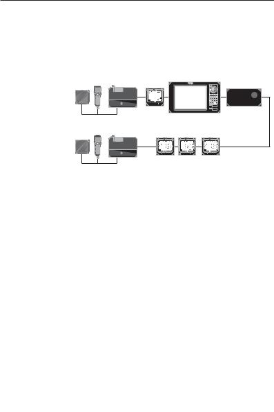
8.3.6.3 Device instance
This option will normally only be used on very large, complicated systems, where there is more than one RS80 system on the same SimNet bus. For example, on certain vessels it may be necessary to have more than one VHF radio fitted with different channel configurations (Fig 8.14).
VHF nº 1
|
|
|
|
|
|
|
|
|
|
|
|
|
|
|
|
|
|
|
|
|
|
|
|
|
|
|
|
|
|
|
|
VHF nº 2 |
|||||||
|
|
Fig 8.14 - Multiple RS80 VHFs on the same network |
|||||||
|
To prevent conflict across the network, these can each be |
||||||||
|
assigned a unique device number. |
||||||||
NOTE |
“More than one RS80 system” refers to a complete system |
||||||||
|
radio, including the Rx/Tx transceiver, NOT to a single RS80 |
||||||||
|
with multiple stations – that is still classed as one radio. |
||||||||
|
From the SimNet management menu select “DEVICE |
||||||||
|
INSTANCE” and press OK. |
||||||||
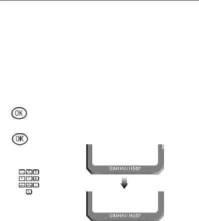
The default device instance number is “000”. Use the numeric keypad to enter the required device instance number and press OK to confirm (Fig 8.15).
SELECT
NO. 000
SELECT
NO. 001
Fig 8.15 - Entering a device number
The display will show “SELECTED” and the entered device number for 2 seconds, then exit to the SimNet management menu.
64 |
E04572 |
Instruction manual
|
8.3.6.4 System instance |
|
A SimNet bus can have a maximum of 50 devices (or “nodes”) |
|
attached to it. If a large vessel has a requirement for more than |
|
50 nodes, then a multiple network system is required. |
|
The system instance allows the user to allocate a unique num- |
|
ber to each network, which allows the multiple networks to |
|
intercommunicate. |
NOTE |
If your vessel is large enough that it is likely to require setting |
|
up multiple networks, it is strongly advised that you contact |
|
Simrad Technical Support to discuss your particular system |
|
requirements before proceeding further. |
|
From the SimNet management menu select “SYSTEM |
|
INSTANCE” and press OK. |
|
The default system instance number is “00”. Use the numeric |
|
keypad to enter the required system instance number and press |
|
OK to confirm (Fig 8.16). |
SELECT
NO. 00
SELECT
NO. 01
Fig 8.16 - Entering a system instance number
The display will show “SELECTED” and the entered system number for 2 seconds, then exit to the SimNet management menu.
E04572 |
65 |
RS81/RS82 VHF
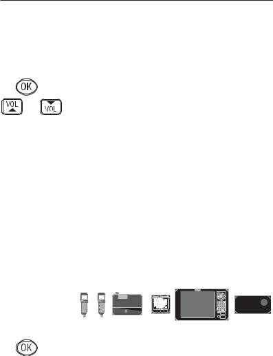
8.3.7 Lighting modes
This option is used to select how the backlighting is controlled on the RS82. Backlighting control can either be limited to the individual station, to the whole RS80 system, or across the SimNet bus.
From the VHF Items menu select “LIGHTING MODES” and press OK.
Use the VOL ▲ and VOL ▼ keys to scroll through the options (Fig 8.17) -
Station All stations are independent.
Radio All stations will respond to a common level.
Network All stations respond to the network level (for the specified lighting bank).
STATION
RADIO
NETWORK
|
|
|
|
|
|
|
|
|
|
|
|
|
|
|
|
|
|
|
|
|
|
|
|
|
|
|
|
|
|
|
|
|
|
|
|
|
|
|
|
|
|
|
|
|
|
|
|
|
|
|
|
|
|
|
|
|
|
|
|
|
|
|
|
|
|
|
|
|
|
|
|
|
|
|
|
Fig 8.17 - Lighting modes |
|||||||
|
|
|
|
|
|
||||||||
|
|
|
|
|
|
||||||||
|
Press Ok to set the selected lighting mode. The display will |
||||||||||||
|
show the lighting mode selected, then exit to the VHF Items |
||||||||||||
|
menu. |
||||||||||||
NOTE |
This option is station specific. It will be necessary to duplicate |
||||||||||||
|
these settings to any other RS80 stations for them all to behave |
||||||||||||
|
in the same manner. |
||||||||||||
66 |
E04572 |
Instruction manual
9 DSC FUNCTIONS
9.1 General
|
The RS82 features full Class D DSC (Digital Selective Calling) |
|
functionality enabling the user to make digitally selected calls, |
|
which are quicker and simpler to make than traditional voice |
|
calls using channel 16. Should a distress situation occur, a |
|
Distress Alert call can be initiated, indicating the vessel’s iden- |
|
tity, position and automatically establish distress communica- |
|
tion on the emergency voice channel (normally channel 16). |
NOTE |
DSC functions will only be available, if the MMSI number has |
|
been entered into the radio (see section 8.2.1). |
9.2 Making a call
9.2.1 Individual routine call
Press the CALL  key to enter the individual routine call function. Enter the MMSI number of the station manually using the numeric keypad, or use the VOL ▲ and VOL ▼ keys to scroll through the MMSI number directory (Fig 9.1). Press OK to confirm the selected entry.
INT 06
|
SEA M I STAA |
|
ON CH 06 00 |
|
Fig 9.1 - Selecting a number from the MMSI directory |
|
Next enter the required reply channel using the numeric key- |
|
pad, or use the VOL ▲ and VOL ▼ keys to scroll through the |
|
four default reply channels (06, 08, 72 & 77). Press OK to con- |
|
firm. |
NOTE |
Only simplex channels can be selected as working channels. |
NOTE |
If the MMSI number entered is for a coast station, the option to |
|
select a working channel will not be available – this is specified |
|
by the coast station, and will normally be a duplex channel. |
|
The display will show “PRESS OK TO SEND” – press OK to |
|
initiate the call, or ON/C to abort. |
E04572 |
67 |
RS81/RS82 VHF
On initiation of the call, the display will show “AWAITING ACKNOWLEDG” (Fig 9.2). Once an acknowledgement is received, the radio will switch to the specified working channel.
|
INT |
06 |
|
|
AWA I T I NGAA |
|
|
ACKNOWLEDG |
|
Fig 9.2 - Call sent, awaiting acknowledgement from recipient |
|
NOTE |
If an acknowledgement is not received, the radio will continue |
|
|
showing “AWAITING ACKNOWLEDG” for 4.5 minutes before |
|
|
timing out and returning to normal operation. |
|
|
9.2.2 Public correspondence call |
|
|
For vessels within range of a country operating the necessary |
|
|
network, the RS82 can be used to directly make and receive |
|
|
public correspondence calls from a land-based telephone sys- |
|
|
tem via a coast station. Press SHIFT, then ON/C to enter the |
|
|
public correspondence call function. |
|
|
Enter the telephone number manually using the numeric key- |
|
|
pad (Fig 9.3), or use the VOL ▲ and VOL ▼ keys to scroll |
|
|
through the telephone number directory. Press OK to confirm |
|
|
the selected entry. |
|
|
INT |
06 |
|
|
44 1 606547 |
|
|
6 7 7 - - - - - - |
|
Fig 9.3 - Dialling a number manually |
|
NOTE |
Check with your local network provider for usage instructions. |
|
68 |
E04572 |
Instruction manual
The next stage is to specify the coast station the call is to be routed through. Either manually enter the MMSI number of the coast station using the numeric keypad, or use the VOL ▲ and VOL ▼ keys to scroll through the Coast Station MMSI directory (Fig 9.4). Press OK to confirm the selected entry.
|
INT |
06 |
|
|
|
COAST |
1 AAA |
|
Fig 9.4 - Selecting a coast station from the Coast Station directory |
||
NOTE |
The MMSI number entered must have a “00”-prefix (which |
||
|
indicates a coast station), or it will not be accepted. |
||
|
The display will show “PRESS OK TO SEND” – press OK to |
||
|
initiate the call, or ON/C to abort. On initiation of the call, the |
||
|
display will show “ATTEMPTING TO CONNECT”. If the call |
||
|
cannot be connected for any reason, the display will show |
||
|
“CANNOT CONNECT”, then “PLS WAIT 15 MINUTES” |
||
|
before returning to the default display. |
||
|
If the call is connected, the display will show “CALL IN |
||
|
PROGRESS” (Fig 9.5) – press the PTT key to talk and release to |
||
|
listen. |
|
|
|
INT |
07 |
|
|
|
CALL |
I N AAA |
|
|
PROGRESSBB |
|
|
Fig 9.5 - Call has been connected |
||
NOTE |
The channel number displayed during the call is determined |
||
|
by the coast station. |
|
|
Press ON/C to end the call, or wait for the other participant to replace the receiver.
E04572 |
69 |
RS81/RS82 VHF
9.2.3 All Ships Safety call
To make an All Ships Safety call, lift the protective cover on the front of the handset and press the SAFETY key. The display will show “SAFETY ON CH 16” (Fig 9.6). Enter the required working channel using the numeric keypad, or use the VOL ▲ and VOL ▼ keys to scroll through the four default reply channels (06, 08, 72 & 77). Press OK to confirm.
|
INT |
06 |
|
|
SAFE TYAAAA |
|
|
ON CH 16 00 |
|
Fig 9.6 - Making an All Ships Safety call |
|
NOTE |
Only simplex channels can be selected as working channels. |
|
|
The display will show “PRESS OK TO SEND” – press OK to |
|
|
initiate the call, or ON/C to abort. |
|
|
9.2.4 All Ships Urgency call |
|
|
To make an All Ships Urgency call, lift the protective cover on |
|
|
the front of the handset and press the URGENCY key. The dis- |
|
|
play will show “URGENCY ON CH 16” (Fig 9.7). |
|
|
INT |
06 |
|
|
URGENCYAAA |
|
|
ON CH 16 00 |
|
Fig 9.7 - Making an All Ships Urgency call |
|
NOTE |
All Ships Urgency calls must use channel 16 for voice commu- |
|
|
nication, the option to manually select a working channel is |
|
|
not available. |
|
The display will show “PRESS OK TO SEND” – press OK to initiate the call, or ON/C to abort.
70 |
E04572 |
Instruction manual
|
|
9.2.5 Group call |
|
|
Press the SHIFT key twice to enter the group call function – the |
|
|
|
|
|
display will show the Group ID MMSI number stored in the |
|
|
radio (see also section 8.2.2). |
|
|
Enter the required working channel using the numeric keypad, or |
|
|
use the VOL ▲ and VOL ▼ keys to scroll through the four default |
|
|
reply channels (06, 08, 72 & 77). Press OK to confirm (Fig 9.8). |
|
|
INT 06 |
|
|
026530 1 45 |
|
|
ON CH 06B |
|
|
Fig 9.8 - Making a group call |
NOTE |
Only simplex channels can be selected as working channels. |
|
|
|
When the display changes to show “PRESS OK TO SEND” – |
|
|
press OK to initiate the call, or ON/C to abort. |
|
|
9.2.6 Distress Alert call |
WARNING |
This call should only be made if the vessel is in a genuine |
|
|
|
distress situation. It is an offence to send a Distress Alert call |
|
|
if the vessel or crew are not in danger. |
|
|
The distress button is located under the protective cover on the |
|
|
front of the handset. Press the DISTRESS button to access the |
|
|
|
|
|
|
|
|
Distress Alert call function – the display will show “DISTRESS |
|
|
UNDEFINED” (Fig 9.9). |
INT --
D I STRESSAA
UNDEF I NED b
Fig 9.9 - Distress Alert menu
E04572 |
71 |
 Loading...