


 Loading...
MANUAL
Simrad
AP26 and AP27
Autopilots
This page is intentionally left blank

Instruction manual
Instruction Manual
This manual is intended as a reference guide for operating and correctly installing the AP26 and AP27 autopilots.
Great care has been paid to simplify operation and set-up of the autopilots, however, an autopilot is a complex electronic system. It is affected by sea conditions, speed of the vessel, hull shape and size.
Please take time to read this manual to get a thorough understanding of the operation and system components and their relationship to a complete autopilot system.
Other documentation material that is included in this manual is a warranty card. This must be filled out by the authorized dealer that performed the installation and mailed in to activate the warranty.
20221586B |
1 |

Simrad AP26 and AP27 Autopilots
Document revisions
Rev |
Date |
Written by |
Checked by |
Approved by |
||||
A |
18.03.04 |
|
NG |
ThH |
|
ThH |
||
B |
27.04.04 |
|
|
|
|
|
|
|
|
|
|
|
|
|
|
||
|
|
|
|
|
|
|
|
|
|
|
|
|
|
|
|
|
|
Document history
Rev. A First edition.
Rev. B FU50 substituted by FU25. Part no. for AC40 Power PCB ass’y, page 124 corrected. Added notes in chapter 3.19. Minor corrections in text and display pictures.
2 |
20221586B |
|
|
|
Instruction manual |
|
|
Contents |
|
1 |
System description ....................................................................................... |
9 |
|
|
1.1 |
General .................................................................................................. |
9 |
|
1.2 |
How to use this manual......................................................................... |
9 |
|
1.3 |
System components............................................................................. |
10 |
|
1.4 |
AP26 Control Unit .............................................................................. |
11 |
|
1.5 |
AP27 Control Unit .............................................................................. |
11 |
|
1.6 |
Autopilot Computer ............................................................................ |
11 |
|
1.7 |
RF300 Rudder Feedback unit ............................................................. |
12 |
|
1.8 |
Heading Sensors.................................................................................. |
12 |
|
|
RC36 Rate compass ............................................................................ |
12 |
|
|
RFC35 Electronic Fluxgate Compass (optional)................................ |
12 |
|
|
NMEA compass (optional) ................................................................. |
13 |
|
|
Simrad RGC10 and RGC50 gyrocompasses ...................................... |
13 |
|
1.9 |
Optional equipment............................................................................. |
14 |
|
|
R3000X Remote Control .................................................................... |
14 |
|
|
JS10 Joystick....................................................................................... |
14 |
|
|
FU25 Follow-Up Steering Lever ........................................................ |
14 |
|
|
Multiple stations.................................................................................. |
14 |
2 |
Operation.................................................................................................... |
15 |
|
|
2.1 |
Overview............................................................................................. |
15 |
|
2.2 |
ON/OFF - Standby mode .................................................................... |
17 |
|
|
Flashing course knob icon .................................................................. |
18 |
|
|
Alarms................................................................................................. |
18 |
|
2.3 |
AP26 and AP27 with MSD50 Stern Drive unit.................................. |
18 |
|
|
Zero point setting ................................................................................ |
18 |
|
2.4 |
Follow-Up steering (FU)..................................................................... |
19 |
|
2.5 |
Non-Follow-Up steering (NFU) ......................................................... |
20 |
|
2.6 |
R3000X Remote Control (NFU)......................................................... |
21 |
20221586B |
3 |

Simrad AP26 and AP27 Autopilots
2.7 |
JS10 Joystick (NFU) ........................................................................... |
21 |
2.8 |
Automatic Steering ............................................................................. |
22 |
|
Heading catch...................................................................................... |
22 |
2.9 |
Automatic control of steering parameters........................................... |
23 |
|
Power boat........................................................................................... |
23 |
|
Sailboat................................................................................................ |
24 |
2.10 |
Manual Parameter Selection ............................................................... |
24 |
2.11 |
U-Turn................................................................................................. |
25 |
2.12 |
Dodge in AUTO.................................................................................. |
26 |
2.13 |
Tacking in Auto mode ........................................................................ |
27 |
2.14 |
Navigating with the AP26 and AP27.................................................. |
27 |
|
Setting the waypoint arrival circle ...................................................... |
30 |
2.15 |
Dodge in NAV .................................................................................... |
31 |
2.16 |
Selecting a different Navigation source.............................................. |
31 |
2.17 |
Wind vane steering.............................................................................. |
32 |
2.18 |
Tacking and gybing in Wind mode..................................................... |
33 |
|
Gybing................................................................................................. |
34 |
|
Tack and gybe prevent ........................................................................ |
34 |
2.19 |
Wind steering and navigation ............................................................. |
35 |
|
Operating in WINDNAV mode............................................................. |
37 |
|
RACING ............................................................................................. |
37 |
2.20 |
Multiple station system ....................................................................... |
38 |
2.21 |
Lock function ...................................................................................... |
38 |
2.22 |
User Set-up Menu ............................................................................... |
39 |
|
Alternating Course Knob Icon ............................................................ |
39 |
|
STANDBY Mode ............................................................................... |
39 |
|
AUTO Mode ....................................................................................... |
44 |
|
NAV Mode.......................................................................................... |
45 |
|
WIND Mode ....................................................................................... |
45 |
2.23 |
INFO menu ......................................................................................... |
46 |
|
Course knob icon ................................................................................ |
48 |
4 |
20221586B |

Instruction manual
|
|
INFO menu flowchart ......................................................................... |
49 |
|
|
Alternative mode screens in STBY, AUTO and NAV....................... |
50 |
|
|
INFO menu and Main screen, active unit ........................................... |
50 |
|
|
INFO menu and Main Screen, inactive unit ....................................... |
50 |
3 |
Installation.................................................................................................. |
51 |
|
|
3.1 |
General ................................................................................................ |
51 |
|
3.2 |
Installation checklist ........................................................................... |
51 |
|
3.3 |
Unpacking and handling ..................................................................... |
52 |
|
3.4 |
Determine system configuration ......................................................... |
52 |
|
3.5 |
Autopilot System Layout .................................................................... |
53 |
|
3.6 |
RF300 Rudder feedback installation................................................... |
53 |
|
3.7 |
Autopilot computer installation .......................................................... |
55 |
|
3.8 |
Cable connections ............................................................................... |
55 |
|
3.9 |
Grounding and RFI ............................................................................. |
56 |
|
3.10 |
Drive unit installation.......................................................................... |
58 |
|
|
Connecting a reversible pump ............................................................ |
60 |
|
|
Connecting a hydraulic linear drive.................................................... |
61 |
|
|
Connecting a solenoid valve ............................................................... |
61 |
|
3.11 |
Control unit installation ...................................................................... |
62 |
|
|
Panel mounting of AP26..................................................................... |
62 |
|
|
Alternative panel mounting of AP26 .................................................. |
62 |
|
|
Optional bracket mounting ................................................................. |
63 |
|
3.12 |
ROBNET2 network cables ................................................................. |
63 |
|
|
AP27 connection................................................................................. |
65 |
|
3.13 |
RC36 Rate Compass installation ........................................................ |
65 |
|
3.14 |
RFC35 Fluxgate Compass installation ............................................... |
67 |
|
3.15 |
R3000X Remote Control installation ................................................. |
68 |
|
3.16 |
JS10 Joystick....................................................................................... |
68 |
|
3.17 |
S35 NFU Lever installation ................................................................ |
68 |
|
3.18 |
Interfacing ........................................................................................... |
69 |
|
3.19 |
SimNet................................................................................................. |
69 |
20221586B |
5 |

Simrad AP26 and AP27 Autopilots
|
SimNet network cables ....................................................................... |
70 |
|
SimNet power and termination ........................................................... |
70 |
3.20 |
Single NMEA input/output................................................................. |
75 |
3.21 |
Double NMEA input/output ............................................................... |
75 |
3.22 |
NMEA output on Port 2...................................................................... |
76 |
3.23 |
NMEA Compass input........................................................................ |
76 |
3.24 |
Radar Clock/Data................................................................................ |
77 |
3.25 |
IS15 Instrument installation................................................................ |
77 |
3.26 |
External Alarm.................................................................................... |
79 |
3.27 |
LF3000 Linear Feedback .................................................................... |
79 |
4 Configuration and setup ........................................................................... |
83 |
|
4.1 |
First time turn on................................................................................. |
83 |
4.2 |
Description of Installation Settings..................................................... |
84 |
4.3 |
Installation Menu ................................................................................ |
85 |
|
Language selection.............................................................................. |
87 |
4.4 |
Dockside settings ................................................................................ |
87 |
|
Boat type ............................................................................................. |
88 |
|
Drive unit voltage................................................................................ |
88 |
|
Rudder Feedback Calibration ............................................................. |
89 |
|
Rudder Test ......................................................................................... |
90 |
|
Drive engage ....................................................................................... |
91 |
|
Rudder Deadband................................................................................ |
92 |
|
Wind setup .......................................................................................... |
92 |
|
Minimum wind angle (NORMAL)..................................................... |
93 |
|
Minimum wind angle (RACING)....................................................... |
93 |
|
Tack angle (RACING)........................................................................ |
93 |
|
Tack time (RACING).......................................................................... |
94 |
|
Wind shift alarm limit (RACING)...................................................... |
94 |
4.5 |
Interface Settings................................................................................. |
95 |
4.6 |
Display units ....................................................................................... |
95 |
4.7 |
Sea Trial .............................................................................................. |
96 |
6 |
20221586B |
|
|
|
Instruction manual |
|
|
Set Rudder zero................................................................................... |
97 |
|
|
Minimum rudder ................................................................................. |
97 |
|
|
Compass calibration............................................................................ |
98 |
|
|
Compass Offset ................................................................................. |
100 |
|
|
Wind Offset....................................................................................... |
101 |
|
|
Wind damping................................................................................... |
101 |
|
|
Depth Offset...................................................................................... |
102 |
|
|
Automatic tuning............................................................................... |
102 |
|
|
Transition Speed ............................................................................... |
103 |
|
|
Init NAV ........................................................................................... |
104 |
|
4.8 |
Parameters......................................................................................... |
104 |
|
|
Manual parameter adjust................................................................... |
105 |
|
|
Recall Autotuned?............................................................................. |
107 |
|
4.9 |
Service Menu .................................................................................... |
107 |
|
|
System Data Menu ............................................................................ |
108 |
|
|
SimNet and NMEA Data Screen ...................................................... |
108 |
|
|
NMEA Port test (AC hardware) ....................................................... |
110 |
|
|
SimNet setup ..................................................................................... |
110 |
|
|
Master Reset...................................................................................... |
112 |
|
|
Final sea trial..................................................................................... |
112 |
|
|
Providing user training...................................................................... |
113 |
5 |
Maintenance ............................................................................................. |
115 |
|
|
5.1 |
Control unit ....................................................................................... |
115 |
|
5.2 |
Autopilot Computer .......................................................................... |
115 |
|
5.3 |
Rudder Feedback............................................................................... |
115 |
|
5.4 |
Compass ............................................................................................ |
115 |
|
5.5 |
Drive unit .......................................................................................... |
115 |
|
5.6 |
Exchange of software programme .................................................... |
116 |
|
|
Autopilot Computer .......................................................................... |
116 |
|
|
Autopilot Control Unit...................................................................... |
117 |
20221586B |
7 |

Simrad AP26 and AP27 Autopilots
6 |
Trouble shooting ...................................................................................... |
118 |
|
|
6.1 |
Alarms............................................................................................... |
118 |
7 |
Spare Parts List........................................................................................ |
123 |
|
8 |
Technical Specifications .......................................................................... |
126 |
|
|
8.1 |
AP26 and AP27 Autopilot System ................................................... |
126 |
|
8.2 |
AP26 Control Unit ............................................................................ |
127 |
|
8.3 |
AP27 Control Unit ............................................................................ |
129 |
|
8.4 |
Autopilot Computers......................................................................... |
130 |
|
8.5 |
RC36 Rate compass .......................................................................... |
132 |
|
8.6 |
RFC35 Fluxgate compass ................................................................. |
133 |
|
8.7 |
RF300 Rudder Feedback................................................................... |
133 |
|
8.8 |
R3000X Remote Control .................................................................. |
135 |
|
8.9 |
JS10 Joystick..................................................................................... |
135 |
|
8.10 |
FU25 Steering Lever......................................................................... |
136 |
|
8.11 |
IS15 Rudder ...................................................................................... |
137 |
|
8.12 |
SimNet............................................................................................... |
138 |
|
8.13 |
IP protection...................................................................................... |
139 |
|
8.14 |
NMEA and SimNet messages........................................................... |
140 |
9 |
Glossary .................................................................................................... |
144 |
|
10 |
Index.......................................................................................................... |
147 |
|
SALES AND SERVICE WORLDWIDE
TERMS OF WARRANTY
WARRANTY CARD
8 |
20221586B |
System Description
1 SYSTEM DESCRIPTION
1.1General
Congratulations on the purchase of your new Simrad autopilot system and thank you for selecting what we feel is the most advanced autopilot system available on the market today.
Today, Simrad manufactures a complete range of autopilots for all types of vessels, from recreational boats to merchant marine vessels. Our factory for these products, Simrad Egersund AS, is located in Egersund on the southwest coast of Norway. The company's involvement in autopilots began in 1953 with equipment for the North Sea fishing fleet under the brand name Robertson. Professional mariners around the world acknowledge that the Robertson and Simrad brand names are synonymous with the absolute best in autopilot technology.
The Simrad AP26 and AP27 autopilots represents yet another step forward in autopilot technology with the intent of providing leisure boats between 30 and 80 foot with a host of new features. The system can be expanded and enhanced with a selection of options and accessories.
The brain in the autopilot system is the single "intelligent" autopilot computer that communicates on the Robnet2 network. The Robnet2 has been developed to establish a reliable digital communication and power distribution network between the units in the autopilot system.
In the AP26 and AP27 autopilots Simrad introduces the new SimNet data and control network. SimNet provides high speed data transfer and control between Simrad products that are integrated as a total steering and navigation system onboard.
1.2How to use this manual
This manual is intended as a reference guide for operating, installing and maintaining the Simrad AP26 and AP27 autopilots. Great care has been paid to simplify operation and set-up.
Please take time to read this manual to get a thorough understanding of the operation and system components and their relationship to a complete autopilot system.
20221586B |
9 |

Simrad AP26 and AP27 Autopilots
Other documentation material that is provided with your system includes a warranty card. This must be filled out by the authorized dealer that performed the installation and mailed in to activate the warranty.
1.3System components
A basic autopilot system consists of the following units (refer to Figure 1-1):
•AP26 Control Unit or AP27 Control Unit with accessories
•Autopilot Computer
•Rate compass
•Rudder Feedback Unit with transmission link
•Drive unit
The basic system can be expanded with multiple fixed and hand held full function control units, hand held remote and steering lever.
AUTOPILOT
COMPUTER
|
|
|
|
|
|
|
|
|
|
RATE |
|
|
|
|
|
|
|
|
|
|
|
|
|
|
|
|
|
|
|
|
|
|
|
|
|
|
|
|
|
|
|
|
|
|
|
|
|
|
|
|
|
|
|
|
|
AP26 |
|
|
|
|
|
|
|
||
|
|
|
|
|
|
|||||
|
|
|
|
|
|
|||||
|
|
|
|
|
|
|
|
COMPASS |
||
CONTROL |
|
|
|
|
|
|
|
|||
|
|
|
|
|
|
|
|
|||
|
UNIT |
|
|
|
|
|
|
|
|
|
REVERSIBLE |
RF300 |
PUMP |
RUDDER |
|
FEDDBACK |
Figure 1-1 AP26 Basic system
10 |
20221586B |

System Description
|
AUTOPILOT |
|
COMPUTER |
AP27 |
|
CONTROL |
|
UNIT |
RATE |
|
|
|
COMPASS |
REVERSIBLE |
RF300 |
PUMP |
RUDDER |
|
FEDDBACK |
Figure 1-2 AP27 Basic System
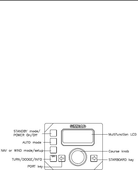
1.4AP26 Control Unit
A compact autopilot control for panel, bulkhead or bracket mounting. It has a multifunction LCD display for readout of autopilot data, mode keys and a rotary course knob. It has two Robnet2 connectors for system interconnection and expansion and two SimNet connectors for control and data sharing with other Simrad products. A NMEA2000 Adapter Cable is available for interface through a SimNet port (page 125).
1.5AP27 Control Unit
A portable control unit with 7 m (20 ft.) of cable. It has the same autopilot functions as AP26 and can be used as a hand held autopilot or be mounted in a fixed, bracket mount.
1.6Autopilot Computer
The autopilot computer is the heart in the autopilot system. It contains the steering computer, interface to other system components, NMEA 0183 interface and drive electronics for the drive unit motor and clutch. Three models, AC10, AC20 and AC40 are available.
20221586B |
11 |

Simrad AP26 and AP27 Autopilots
Autopilot computer comparison chart:
|
AC10 |
AC20 (AC40) |
Supply voltage |
10-28 V |
10-40 V |
Motor current (continuous/peak) |
6/10 A |
10/20A (20/40A) |
Clutch/bypass current |
1,5 A* |
1,5 A* |
Number of control units |
2 |
7 |
NMEA 0183 ports (input/output) |
1 |
2 |
Solenoid output |
x |
x |
Input for NFU control |
x |
x |
External alarm |
|
x |
Radar clock/data interface |
|
x |
Input for NMEA compass |
|
x |
*3A on later models.
1.7RF300 Rudder Feedback unit
Rudder feedback unit with transmission link and 10 m (30 feet) of cable. Transforms the angular travel of the rudder to a digital signal read by the autopilot steering computer.
1.8Heading Sensors
The AP26 and AP27 autopilots can be used with the following combinations of heading sensors:
RC36 Rate compass
Fluxgate compass with integrated rate sensor. Provides a dramatic improvement to the dynamic performance of both the autopilot and a stabilized radar display.
RC36 comes as standard with the autopilot.
RFC35 Electronic Fluxgate Compass (optional)
A compact heading sensor from Simrad with 15 m (45 feet) of cable. The direction of the earth's magnetic field is sensed by a
12 |
20221586B |

System Description
floating ring core in a fluxgate coil and transformed to a digital signal read by the autopilot steering computer.
RFC35 can operate as a low cost back-up compass for the AP26 and AP27 autopilots.
NMEA compass (optional)
A well performing compass that outputs NMEA 0183 HDT or HDG messages at 10 Hz can be connected directly to the AC20 or AC40 autopilot computer.
It is absolutely necessary for the autopilot that the heading rate is minimum 10 Hz.
Simrad RGC10 and RGC50 gyrocompasses
The optional GI51 unit is needed to interface these two gyrocompass models. Ask your Simrad dealer for information.
20221586B |
13 |

Simrad AP26 and AP27 Autopilots
1.9Optional equipment
A series of optional equipment are available for the basic AP26 and AP27 systems.
R3000X Remote Control
A small handheld remote control with two push buttons for power steering or course selection (port and starboard), and one push button with built-in lighted indicator for limited mode change.
JS10 Joystick
The JS10 Joystick is a Non-Follow-Up steering lever designed for indoor and outdoor console mount. It has a spring-loaded return-to-mid-position feature and is equipped with 10 m (33’) of cable and installation hardware.
FU25 Follow-Up Steering Lever
The FU25 Follow-up steering lever features a dial with 5° rudder angle markings. The rudder will move and stop at the angle selected on the dial. The FU25 has a mid-position indent, buttons for (limited) mode selection, and mode indicators. It is designed for indoor and outdoor bulkhead or flush panel-mounting. Refer to the FU25 manual for more information.
Multiple stations
Multiple control units can be added to the system. See page 11
14 |
20221586B |
Installation
2 OPERATION
WARNING ! An autopilot is a very useful navigational aid, but DOES NOT under any circumstance replace a human navigator.
Do not use automatic steering when:
•In heavy traffic areas or in narrow waters
•In poor visibility or extreme sea conditions
•When in areas where use of autopilot is prohibited by law
When using an autopilot:
•Do not leave the helm unattended
•Do not place any magnetic material or equipment near heading sensor used in the autopilot system
•Verify at regular intervals course and position of vessel
•Always switch to Standby mode and reduce speed in due time to avoid hazardous situations
2.1Overview
STBY
PWR
AUTO
NAV
WIND
SETUP
DODGE
INFO
Figure 2-1 AP26 Front Panel
20221586B |
15 |

Simrad AP26 and AP27 Autopilots
STBY AUTO
PWR
NAV
WIND DODGE
SETUP INFO
Figure 2-2 AP27 Front Panel
The control units shown above can operate as a stand alone unit in an autopilot system or combined in a multistation system. In a multistation system the command can easily be transferred from one unit to another. Units not in control will display "Inactive" and/or  .
.
The autopilot system is capable of the following primary steering modes: STBY (power steering), AUTO, NAV and WIND, each mode having a dedicated push button.
Each of the mode push buttons is clearly identified with the primary function in large text, and a secondary function listed in smaller text. Each button provides you with a multiple function mode display.
A group of user adjustable settings are provided in the User Setup Menu (page 39).
Alarms are presented in plain text to alert you of system and external data failure conditions. Alarms include both audible and visual presentations. The alarm listing is on page 118.
16 |
20221586B |

Installation
2.2ON/OFF - Standby mode
Note ! At first time turn on see paragraph 4.1.
A single press on the STBY button switches the system ON and the following status displays are shown:
Autopilot model
Software version
SimNet no.
Simrad
AP26
SW 1.0.00 HW rev. 00 Sn xxxxxx
Software release Hardware revision
Autopilot computer model
Software version
Power board revision Main board revision
Simrad
AC20
SW 1.0.00
P00 M00 S000 Software release
Self check
SW and HW revisions shown are examples only.
After approximately 5 seconds, the system is operative and the unit that was turned on will show the Standby mode display. Other units in a multistation system will display "Inactive". Control is transferred to any single unit by pressing its’ STBY button.
The main Standby mode display shows the current heading.
Alternatively, the Standby mode display can show the following information by a long press on the TURN/DODGE/INFO button:
− Standby mode
− Current heading 345°M
− Compass source: Rate compass
− Rudder angle =00°. Refer to INFO menu, page 46.
20221586B |
17 |

Simrad AP26 and AP27 Autopilots
A long press (2-3 sec.) on the STBY button switches the system OFF and during this time, the alarm will sound.
Note ! In an emergency, it is possible, on a multistation system, to turn OFF the system at any control unit by pressing the STBY button for 2-3 seconds.
STBY mode is the mode that is used when steering the boat at the helm.
Flashing course knob icon
When the course knob and the PORT/STBD buttons are used for settings etc., an icon will flash on the screen to tell that no course changes can be made unless you press the AUTO button.
Alarms
In the event there is an audible alarm with explaining text on the control unit, refer to section 6 Trouble shooting.
2.3 AP26 and AP27 with MSD50 Stern Drive unit
Note ! The information in section 2.3 only applies if your autopilot is driving a Simrad MSD50 Stern Drive.
The MSD50 Stern drive unit has a relative feedback signal which needs a zero point setting after the autopilot has been turned on. Refer to the MSD50 manual for further information.
Zero point setting
Note ! If you do not need a rudder angle display when leaving the dock, just steer the boat manually on a straight course and press the AUTO button. The zero point is then set automatically.
If you prefer to use the rudder angle display when leaving the dock, proceed as follows:
After turn on the rudder angle display will alternate between 10 degrees port and starboard to indicate that the "rudder" zero point need be set.
18 |
20221586B |
Installation
Use the wheel to bring the "rudder" to midship position. Turn the wheel from lock to lock (H.O. to H.O.) and count the exact number of turns. Then start from one lock position and turn the half number of turns.
Press AUTO and then STBY. The zero point is now set and the display will show:
Follow the operating instructions on the following pages. There is no further need for zero point settings until next time you turn the autopilot on.
2.4Follow-Up steering (FU)
In the Follow-Up steering mode the course knob may be used to set rudder commands. The commanded rudder angle is shown on the display and the rudder will move to the commanded angle and stop.
Press both buttons |
Use course |
|
|
simultaneously to |
knob to |
Commanded rudder angle 10° to |
|
activate Follow- |
command |
||
port. Rudder angle: 4° to port |
|||
Up |
rudder angle |
||
and moving. |
|||
|
|
Return to manual control in Standby by pressing the STBY button
WARNING ! While in Follow-up mode you cannot take manual control of the wheel.
20221586B |
19 |
Simrad AP26 and AP27 Autopilots
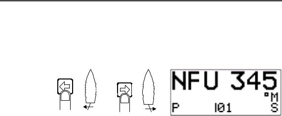
2.5Non-Follow-Up steering (NFU)
In Standby mode, the NFU display is presented when the PORT or STBD button is pressed. The rudder will move as long as the button is pressed and the rudder angle is shown on the display.
Activates |
Activates |
PORT rudder |
STBD |
command |
rudder |
|
command |
Note ! When a NFU steering lever or remote control is operated, other control units become “Inactive”.
20 |
20221586B |

Installation
2.6R3000X Remote Control (NFU)
SIMRAD
Push button for Port and Stbd commands
STBY-AUTO
STBY/automatic.
Automatic modes are active when the lamp is lit.
Simrad R3000X
Notes !
In STANDBY mode, the rudder will move as long as the Port or Stbd button is pressed.
In AUTO mode and Wind modes the set course or set wind angle will change 1° each time the button is pressed.
Note!
If you keep the button pressed, it will automatically change the setting in increments of 3° per second.
Mode changes are as per table below.
Initial mode |
1st press |
2nd press |
STBY |
AUTO |
STBY |
AUTO |
STBY |
AUTO |
NAV |
STBY |
AUTO 1)3) |
STBY |
WIND |
STBY 2) |
AUTO |
STBY |
WIND 2) |
WIND |
STBY |
WIND 2) |
WINDN |
STBY |
WIND 3) |
1.When NAV mode is selected in User Setup
2.When WIND mode is selected in User Setup
3.NAV and WINDN modes can only be entered from the Control unit because you have to accept the prompt displays.
2.7JS10 Joystick (NFU)
The principle is similar to that of R3000X Remote Control (see above). The rudder will move as long as the lever is offset to Port or Starboard. JS10 has no mode change feature.
Note ! When a NFU steering lever or a remote control is operated, the control units and FU25 become "Inactive".
20221586B |
21 |

Simrad AP26 and AP27 Autopilots
2.8Automatic Steering
When AUTO mode is selected, the autopilot automatically picks the current boat heading as the set course and maintains the simultaneous rudder angle. This gives a bumpless transfer at the mode change.
The main Auto mode display shows the mode index and the set course.
Alternatively, the Standby mode display can show the following information by a long press on the TURN/DODGE/INFO button:
Automatic steering mode Set course: 340 degrees Steering parameter: LO-A Compass reading: 340°M Rudder angle: 00°
Refer to INFO menu, page 46.
The autopilot will keep the boat on the set course until a new mode is selected or a new course is set with the course knob or the PORT or STBD buttons. One revolution of the course knob equals a 45° course change.
Decrease Increase |
|
|
Course adjust 1° |
Course change |
|
(or 10°)/ push |
CCW: Decrease |
CW: Increase |
Note ! On power boats it is possible in the User Setup menu to set the buttons to change the course by 10° per press (see page 45).
Once the course is changed to a new set course, the boat will automatically turn to the new heading and continue to steer straight.
Heading catch
When in Auto mode this feature allows you to automatically cancel the turn you are in by an instant press on the AUTO
22 |
20221586B |
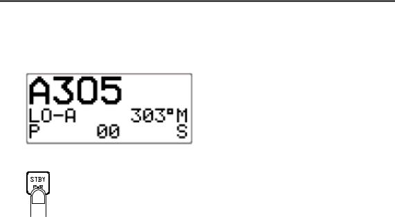
Installation
button. The autopilot will immediately counteract the turn and the boat will continue straight ahead on the heading read from the compass the very moment you pressed the AUTO button.
Automatic steering mode New “caught” heading: 305°
Compass reading: 303° M (magnetic) or T (true)
Rudder angle: 00°. Steering parameter: LO-A
Regain manual steering by pressing the STBY button
2.9Automatic control of steering parameters
The autopilot provides two different sets of steering parameters for controlling the response of the boat at different speeds or wind directions while in AUTO, NAV or WIND modes.
Power boat
The autopilot selects the LO (response) steering parameters when engaging an automatic mode from STBY provided there is no speed input. This is a safety feature. When entering an automatic mode at low speed, the steering parameters may be changed to HI automatically by input data from a speed log or a GPS navigator, or manually.
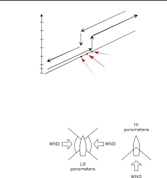
The speed at which the autopilot automatically changes from LO to HI parameters (or opposite) is determined by the "Transition Speed" set in the Installation Setup Menu (Sea trial). See diagram below.
Legend
HI-A High response parameters set automatically LO-A Low response parameters set automatically HI-M High response parameters set manually LO-M Low response parameter set manually
20221586B |
23 |
Simrad AP26 and AP27 Autopilots
Speed
26 |
|
|
|
|
|
|
|
|
|
|
|
|
|
|
|
|
|
|
24 |
|
|
|
|
|
|
|
|
|
|
|
|
|
|
|
|
|
|
22 |
|
|
|
|
|
|
|
|
|
|
|
|
|
|
|
|
|
|
20 |
|
|
|
|
|
|
|
|
|
|
|
|
|
|
|
|
|
|
18 |
|
|
|
|
|
|
|
|
|
|
|
|
|
|
|
|
|
|
16 |
|
|
|
|
|
|
|
|
|
|
|
|
|
|
|
|
|
|
14 |
|
|
|
|
|
|
|
|
|
|
|
|
|
|
|
|
|
|
12 |
|
|
|
|
|
|
|
|
|
|
|
|
|
|
|
|
|
|
10 |
|
|
|
|
|
|
|
|
|
|
|
|
|
|
|
rs |
|
|
|
|
|
|
|
|
|
|
|
|
|
|
|
|
|
|
|
||
|
|
|
|
|
|
|
|
|
|
|
|
|
|
|
|
|
||
|
|
|
|
|
|
|
|
|
|
|
|
|
|
|
|
|
|
|
8 |
|
|
|
|
|
|
|
|
|
|
|
ra |
|
te |
|
|
||
|
|
|
|
|
|
|
|
|
|
|
e |
|
|
|
||||
|
|
|
|
|
|
|
|
|
|
|
a |
m |
|
|
|
|
||
6 |
|
|
|
|
|
o |
|
|
p |
|
|
|
|
|
|
|
||
|
|
|
|
|
|
e |
|
|
|
|
|
|
|
|
||||
|
|
|
|
|
|
|
|
s |
|
|
|
|
|
|
|
|
|
|
|
|
|
|
|
p |
n |
|
|
|
|
|
|
|
|
|
|
||
|
|
|
|
s |
|
|
|
|
|
|
|
|
|
|
|
|
|
|
4 |
H |
|
e |
|
|
|
|
|
|
|
|
|
|
|
|
|
|
|
|
|
r |
|
|
|
|
|
|
|
|
|
|
|
|
|
|
|
|
|
I |
|
|
|
|
|
|
|
|
|
|
|
|
|
|
|
|
|
2 |
|
|
|
|
|
|
|
|
|
|
|
|
|
|
|
|
|
|
0 |
|
|
|
|
|
|
|
|
|
|
|
|
|
|
|
|
|
|
|
|
|
|
|
|
|
|
|
|
|
|
|
rs |
|
|
|
|
|
|
|
|
|
|
|
|
te |
|
|
|
|
|
|
|
|
|
|
|
|
e |
|
|
|
|
|
|
|
|
|
|
|
|
m |
|
|
|
|
|
|
|
|
|
|
|
|
a |
|
|
|
|
|
|
|
|
|
|
|
|
|
r |
|
|
|
|
|
|
|
|
|
|
|
|
a |
|
|
|
|
|
|
|
|
|
|
|
|
p |
|
|
|
|
|
|
|
|
|
|
|
|
e |
|
|
|
|
|
|
|
|
|
|
|
|
s |
|
|
|
|
|
|
|
|
|
|
|
|
n |
|
|
|
|
|
|
|
|
|
|
|
|
o |
|
|
|
|
|
|
|
|
|
|
|
|
p |
|
|
|
|
|
|
|
|
|
|
|
|
s |
|
|
|
|
|
|
|
|
|
|
|
|
|
re |
|
|
|
|
|
|
|
|
|
|
|
|
O |
|
|
|
|
|
|
|
|
|
|
|
|
|
L |
|
|
|
|
|
|
|
|
|
|
|
|
|
Transition to LO parameters with increasing speed: 10 Knots
Transition Speed set to 9 Knots
Transition to HI parameters with decreasing speed: 8 Knots
Sailboat
When sailing in WIND mode, the parameters are automatically changed by the direction of the wind as per below or by the boat speed.
The transition between HI and LO parameters and vice versa will have a different characteristics with regards to the wind angle compared with the transition controlled by the speed of the boat.
If you loose too much speed e.g. when tacking, the parameters will change to HI to gain sufficient rudder response. This should be observed when setting the transition speed on sailboats.
2.10Manual Parameter Selection
Manual selection of steering parameters is necessary if there is no speed input to the autopilot or if you want to override the automatic control.
24 |
20221586B |

Installation
To toggle between LO and HI parameters, press the "AUTO" button two times quickly.
Quick double press
Notes !
1.If you are in NAV or WIND modes you need not enter AUTO mode to manually change the parameter set. Just make a quick double press on the AUTO button.
2.The manually selected setting (HI or LO) will override the automatic selection and remain in effect until you re-enter any automatic mode from STBY.
2.11U-Turn
This feature is very useful in a man overboard situation and whenever you want to steer back on a reciprocal heading.
U-Turn changes the current set course to be 180 degrees in the opposite direction. The user must decide whether the U-Turn should be made to Port or Starboard when bringing the boat on the new course. U-Turn is activated by a quick press on the TURN/DODGE/INFO button. The autopilot will continue on the set course until you press either the PORT or STBD button to select the direction to make the U-Turn. If you do not press PORT or STBD within 1 minute, the autopilot will return to the AUTO mode and stay on course.
Press |
Select |
Boat |
|
makes |
|||
TURN/DODGE |
STBD |
||
STBD |
|||
/ INFO to enter |
U-turn |
||
U-turn |
|||
U-TURN |
|
||
|
|
20221586B |
25 |

Simrad AP26 and AP27 Autopilots
2.12Dodge in AUTO
Dodging is useful in situations where you need to quickly take control of the helm to steer around an obstruction, and then resume the previous set heading. Dodging is activated by a quick double press on the TURN/DODGE/INFO button.
When in DODGE mode the displayed set course is the last one set prior to activating the dodge function. When DODGE is displayed, the autopilot is no longer in control of the steering, and you must either manually steer the boat in STBY mode or take control using Non Follow Up or Follow Up steering. On manual steering (STBY mode) the clutch or bypass valve in the drive unit will be disengaged. The autopilot will remain in the DODGE mode until you exit DODGE by a second press on the TURN/DODGE/INFO button or select a mode.
Quick double press to activate
Dodge mode
Perform dodging in one of the following ways:
1.Manually steer the boat by the wheel:
2. |
Non Follow Up steering |
or using NFU |
|
by pressing: |
steering lever |
|
|
or |
3. |
Follow Up steering by |
and using the |
|
pressing both: |
course knob |
To return from Dodge mode, press one of the following:
Selects |
AUTO |
|
Selects AUTO |
|
mode |
and |
or |
mode with the |
|
returns |
to the |
current heading as |
||
|
||||
last set course |
|
the set course |
||
Note ! Using NFU or FU modes while dodging will make “NFU” or “FU” flash instead of “DODGE”.
26 |
20221586B |

Installation
2.13Tacking in Auto mode
The tack function is only available in sailboats when the system is set up for SAIL boat type in the installation setup.
Tacking in AUTO mode is different from tacking in WIND mode. In AUTO mode the tack angle is fixed and can be set in the Installation/Dockside menu.
Tacking should only be performed into the wind and must be tried out in calm sea conditions with light wind to find out how it works on your boat. Due to a wide range of boat characteristics (from cruising to racing boats) the performance of the tack function may vary from boat to boat. Except for the fixed course change and the difference in displays, the procedure is similar to that of the U-Turn described on page 25.
Press to enter |
Select |
|
TACK mode |
STBD |
Boat |
|
tack |
|
|
makes |
|
|
|
|
|
|
STBD |
|
|
tack |
2.14Navigating with the AP26 and AP27
The autopilot has the capability to use steering information from an external navigator (GPS, Chart Plotter) to direct the boat to a specific waypoint location, or through a route of waypoints. In the NAV mode, the autopilot uses the compass as heading source for course keeping. The information received from the navigator alters the set course to keep the boat on the track line and direct the autopilot to the destination waypoint.
Note ! Navigational steering should only be used in open waters. By selecting the NAV mode, the autopilot is set for automatic steering on the current set course and then waits for the user to accept the course change to the track line or destination waypoint.
To obtain satisfactory navigation steering, the following points must be fulfilled prior to entering the NAV mode:
20221586B |
27 |
Simrad AP26 and AP27 Autopilots
•The autopilot autosteering must be tested and determined satisfactory.
•The navigation receiver (GPS, Chart Plotter) must be in full operating mode with adequate signal characteristics for valid position and navigation data.
•At least one waypoint must be entered and selected as the current “Go to” waypoint.
•The navigation receiver (source) for the autopilot will be the one that is automatically selected in the interface set-up or manually selected in the User setup menu item called “Source select” (page 42).
The autopilot is designed to steer in “mixed mode” operation. This combines the straight steering capability of cross track error (XTE) steering in conjunction with the turning capability of bearing mode steering (Course To Steer, CTS) and automatic waypoint shift.
Note ! If the autopilot is connected to a navigation receiver that does not transmit a message with bearing to next waypoint, it will pick a XTE message and steer on Cross Track Error only. In that case you have to revert to AUTO mode at each waypoint and manually change set course to equal bearing to next waypoint and then select NAV mode again.
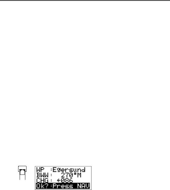
Press the NAV button to activate the NAV prompt display.
NAV |
The prompt display |
shows |
the |
|
|
|
|
|
|
|
name or number of the next |
|||
|
waypoint (WP), the bearing of the |
|||
|
track line (BWW) from the |
|||
|
previous |
waypoint |
to |
the |
|
destination waypoint, the required |
|||
|
course change (CHG) and the |
|||
|
direction in which the boat will |
|||
|
turn. |
|
|
|
Note ! If only one waypoint has been entered the bearing will be from the present position to the destination waypoint.
Press the NAV button again to accept the waypoint as the location to steer towards. The autopilot turns the boat onto the track line.
28 |
20221586B |
Loading...