


Navico Marine Network Systems
2 kW Radar
Installation Guide
MN000802A-G

1 2 kW Radar Installation Manual
1.1 FCC Statement
Note: This equipment has been tested and found to comply with the limits for a Class B digital device, pursuant to Part 15 of the FCC Rules. These limits are designed to provide reasonable protection against harmful interference in a normal installation. This equipment generates, uses and can radiate radio frequency energy and, if not installed and used in accordance with the instructions, may cause harmful interference to radio communications. However, there is no guarantee that interference will not occur in a particular installation. If this equipment does cause harmful interference to radio or television reception, which can be determined by turning the equipment off and on, the user is encouraged to try to correct the interference by one or more of the following measures:
•Reorient or relocate the receiving antenna.
•Increase the separation between the equipment and receiver.
•Connect the equipment into an output on a circuit different from that to which the receiver is connected.
•Consult the dealer or an experienced technician for help.
•A shielded cable must be used when connecting a peripheral to the serial ports.
1.2 Industry Canada
Operation is subject to the following two conditions (1) this device may not cause interference, and (2) this device must accept any interference, including interference that may cause undesired operation of the device.
Refer also to the system specifications section.
1.3 CE Compliance
Hereby, Navico New Zealand, declares that this Radar Processor is in compliance with the essential requirements and other relevant provisions of Directive 1999/5/EC.
1.4 Intro: Disclaimer
As Navico is continuously improving this product we retain the right to make changes to the product at any time which may not be reflected in this version of the manual. Please contact your nearest distributor if you require any further assistance.
It is the owner’s sole responsibility to install and use the instrument and transducers in a manner that will not cause accidents, personal injury or property damage. The user of this product is solely responsible for observing safe boating practices.
NAVICO HOLDING AS. AND ITS SUBSIDIARIES, BRANCHES AND AFFILIATES DISCLAIM ALL LIABILITY FOR ANY USE OF THIS PRODUCT IN A WAY THAT MAY CAUSE ACCIDENTS, DAMAGE OR THAT MAY VIOLATE THE LAW.
Governing Language: This statement, any instruction manuals, user guides and other information relating to the product (Documentation) may be translated to, or has been translated from, another language (Translation). In the event of any conflict between any Translation of the Documentation, the English language version of the Documentation will be the official version of the Documentation.
This manual represents the product as at the time of printing. Navico Holding AS. and its subsidiaries, branches and affiliates reserve the right to make changes to specifications without notice.
Copyright © 2007 Navico Holding AS.
2 kW Radar Installation Manual | 1
1.5 Warranty
The Navico Warranty Statement is supplied as a separate document. It is shipped with the Product Registration Card.
In case of any queries, refer to the Manufacturer of Radar/Chart/Multifunction Displays
1.6 Feedback from you
Your feedback is important and helps Navico ensure that this manual is a valuable resource for all marine technicians. E-mail your comments or suggestions about this manual to the following address: manuals@navico.com
2 | 2 kW Radar Installation Manual
Contents |
|
|
1 2 kW Radar Installation Manual |
1 |
|
1.1 |
FCC Statement ........................................................................................................ |
1 |
1.2 |
Industry Canada ...................................................................................................... |
1 |
1.3 |
CE Compliance ........................................................................................................ |
1 |
1.4 |
Intro: Disclaimer ..................................................................................................... |
1 |
1.5 |
Warranty ................................................................................................................ |
2 |
1.6 |
Feedback from you .................................................................................................. |
2 |
2 Preface |
6 |
|
2.1 |
Warnings ................................................................................................................ |
6 |
3 Introduction to the Navico radar system |
8 |
|
3.1 |
2 kw Radar overview ................................................................................................ |
9 |
4 Install the radar |
11 |
|
4.1 |
Choose the scanner location ..................................................................................... |
12 |
4.2 |
Power boat installations ........................................................................................... |
13 |
4.3 |
Yacht installations................................................................................................... |
14 |
4.4 |
How to find the optimum height for the scanner .......................................................... |
14 |
4.5 |
How to find the theoretical maximum detection range .................................................. |
15 |
4.6 |
How to reduce false echoes and shadow zones ............................................................ |
16 |
4.7 |
2 kW scanner dimensions......................................................................................... |
16 |
4.8 |
Install a scanner on a trestle .................................................................................... |
17 |
4.9 |
Install the 2 kW scanner unit .................................................................................... |
17 |
4.10 Install the radar processor...................................................................................... |
18 |
|
5 Check the 2 kW radar parts |
19 |
|
6 Wiring guidelines |
22 |
|
6.1 |
Connect the 2 kW interconnection cable (NS003101) to the scanner............................... |
22 |
6.2 |
Run the 2 kW interconnection cable (NS003100/NS003101) to the radar processor .......... |
26 |
6.3 |
2 kW radar processor connections ............................................................................. |
27 |
6.4 |
Connect the power cable.......................................................................................... |
28 |
6.5 |
Connect the ground wire.......................................................................................... |
29 |
6.6 |
Radar system checklist ............................................................................................ |
29 |
7 Connect Simrad GB40 or Northstar 8000i |
30 |
|
7.1 |
Parts needed to connect radar to a GB40 or 8000i system ............................................ |
30 |
7.2 |
Simrad GB40 connection using SimNet heading........................................................... |
32 |
7.3 |
Northstar 8000i / Simrad GB 40 using NMEA 0183 heading ........................................... |
33 |
7.4 |
Commision the radar using a GB40 or 8000i ............................................................... |
35 |
8 Connect Simrad NX40 / NX45, Northstar M84 / M121 |
38 |
|
8.1 |
Parts needed.......................................................................................................... |
38 |
8.2 |
Connect the 2 kW radar processor to an M84 or M121 Display ....................................... |
39 |
8.3 |
Set up the radar with the Northstar M84 or M121 ........................................................ |
40 |
9 Connect Northstar 6000i / 6100i |
42 |
||
9.1 |
Parts needed to connct to a Northstar 6000i / 6100i .................................................... |
42 |
|
9.2 |
Connect the 2 kW radar processor to a 6000i or 6100i display ....................................... |
43 |
|
9.3 |
Connect the radar communications cable (NS003107) to the junction box ....................... |
45 |
|
9.4 |
Configure the remote power control for a 6000i or 6100i (common power source)............ |
48 |
|
9.5 |
Configure the remote power control for a 6000i or 6100i (different power sources)........... |
48 |
|
9.6 |
Set up the radar with the Northstar 6000i or 6100i ...................................................... |
49 |
|
9.7 |
Turn the radar on and off ......................................................................................... |
49 |
|
9.8 |
Configure the navigator communications .................................................................... |
50 |
|
9.9 |
Adjust the appearance settings ................................................................................. |
50 |
|
9.10 |
Heading sensor requirements.................................................................................. |
51 |
|
9.11 |
Disable the heading sensor input ............................................................................. |
51 |
|
9.12 |
Calibrating the radar.............................................................................................. |
51 |
|
9.13 |
Prepare for calibration ........................................................................................... |
51 |
|
9.14 |
Tune the radar...................................................................................................... |
52 |
|
9.15 |
Set the STC Curve................................................................................................. |
52 |
|
9.16 |
Set the trigger delay.............................................................................................. |
52 |
|
9.17 |
Set the heading calibration (heading sensor installed) ................................................ |
53 |
|
9.18 |
Set the heading calibration (heading sensor not installed) ........................................... |
54 |
|
9.19 |
Restore all the factory settings................................................................................ |
54 |
|
9.20 |
Restore the factory appearance settings ................................................................... |
54 |
|
9.21 |
Manual tuning procedure for the 6000i or 6100i system.............................................. |
55 |
|
10 Connect to Lowrance Displays |
56 |
|
10.1 |
Parts needed to connect to Lowrance displays |
...........................................................56 |
10.2 |
RIM300 ............................................................................................................... |
57 |
10.3 |
Setup the radar with Lowrance displays.................................................................... |
58 |
10.4 |
Setup the basics ................................................................................................... |
59 |
10.5 |
Radar Setup ......................................................................................................... |
60 |
11 Maintenance |
64 |
|
11.1 |
General maintenance............................................................................................. |
64 |
11.2 |
Scanner maintenance ............................................................................................ |
64 |
11.3 |
Scanner maintenance ............................................................................................ |
64 |
11.4 |
Other maintenance items ....................................................................................... |
65 |
11.5 |
Feedback from you................................................................................................ |
65 |
11.6 |
Feedback from you................................................................................................ |
65 |
12 Troubleshoot the radar |
66 |
12.1 Technical support, service and repairs |
......................................................................66 |
12.2 |
Radar is not operating correctly............................................................................... |
66 |
12.3 |
If the scanner fails to turn ...................................................................................... |
66 |
12.4 |
How to reduce noise and interference....................................................................... |
67 |
12.5 |
Make sure the power is present and correctly wired ................................................... |
67 |
12.6 |
Confirm the equipment installed .............................................................................. |
67 |
12.7 |
Confirm the equipment installed .............................................................................. |
68 |
12.8 |
Are range rings displayed? ..................................................................................... |
68 |
13 2 kW radar system specifications |
69 |
|

2 Preface
This manual explains how to install the Navico Radar scanner and the radar processor System. It Explains how to connect to products produced by Navico and sold under the Navico house of brands.
This Radar system can interface to the following equipment.
Ethernet Connectivity
• Simrad GB40
• Northstar 8000i
Serial Connectivity
• Simrad NX40 and NX45
• Northstar 6100
• Northstar M Series
• GlobalMap, LCX, LMS and X ranges of displays. See above list for specific models
This manual should be used in conjunction with the installation manual provided with the display It also explains how to set up the radar system after installation and gives information on troubleshooting.
This manual is written for professional marine technicians, installation technicians, and service technicians, and can be used for information by dealers.
PLEASE READ CAREFULLY BEFORE USE
WARNING indicates a potentially hazardous situation which, if not avoided, could result in death, serious injury or damage to property
2.1 Warnings
Use the radar at your own risk. Your radar was designed for use as a navigation aid. It should not be used for purposes that require precise measurements of direction, distance, topography or location. Always compare the navigation information received from your radar with data from other navigation aids and sources. When a conflict arises between the navigation data from your radar and data from other navigation aids, make sure you resolve the conflict before proceeding with navigation. A CAREFUL NAVIGATOR NEVER RELIES ON ONLY ONE METHOD TO OBTAIN NAVIGATION INFORMATION. Caution:
International Regulations for Preventing Collisions at Sea mandate that when radar is on a vessel, the radar must be used at all times, regardless of weather conditions or visibility. Numerous court decisions have not only ruled the radar must be used, but that the radar operator must be knowledgeable in all operational aspects of radar performance or otherwise face a greater risk of liability if an accident occurs.
WARNING: High Voltage Hazard
Dangerously high voltages are present within the radar scanner unit. Technicians must exercise extreme care when working inside the unit. ALWAYS remove power before removing the cover. Some capacitors may take several minutes to discharge, even after switching off the radar. Before touching the magnetron or any high voltage components, ground them with a clip lead. WARNING: Microwave Radiation Hazard

The microwave energy radiated by a radar antenna is harmful to humans, especially to the eyes. NEVER look directly into an open waveguide or into the path of radiation from an enclosed antenna. Radar and other radio frequency radiation can upset cardiac pacemakers. If someone with a cardiac pacemaker suspects abnormal operation, immediately turn off the radar equipment and move the person away from the antenna. Turn off the radar whenever it is necessary to work on the antenna unit or other equipment in the beam of the radar.
Note! Most countries accept that RF power density levels below 100 W/m2 cause no significant RF hazard.
|
Vertical beam |
Minimum safe distance |
Minimum safe distance |
Scanner |
angle of |
(100 Watts per m² |
(10 Watts per m² |
Model |
scanner |
average power density) |
average power density) |
|
(degrees) |
Note 1 |
Note 2 |
2 kW |
30 |
1.6 ft (0.5 m) |
4.6 ft (1.4 m) |
|
|
|
|
4 kW |
25 |
3 ft (0.9 m) |
9.3 ft (2.8 m) |
|
|
|
|
6 kW |
20 |
3.6 ft (1.1 m) |
11.5 ft (3.5 m) |
|
|
|
|
10 kW |
20 |
9.5 ft (2.9 m) |
30 ft (9.0 m) |
|
|
|
|
25 kW |
20 |
18 ft (5.5 m) |
57 ft (17.4 m) |
|
|
|
|
NOTES: Limits apply to exposure within the vertical beam angle.
Note 1: Peak occupational exposure limit pursuant to IEC 60936 Clause 3.27 and IEC 62252 Clause 4.32
Note 2: General public exposure limit pursuant to IEC 60936 Clause 3.27 and IEC 62252 Clause 4.32

3 Introduction to the Navico radar system
The Navico radar system platform is designed to work with many types and models of display heads that belong to brands under the Navico house of brands
The radar systems consist of a scanner, processor and connection cables. Scanner models are available with power outputs of 2 kW, 4 kW, 6 kW, 10 kW and 25 kW to suit different customer requirements. Each scanner model has a corresponding radar processor module.
Note 10 kW and 25 kW scanners are not compatible with the Simrad NX40 , NX45, Northstar M84 or M121).
Branding information
Brand |
Display heads that support the |
|
Navico radar system |
|
Simrad GB40 network system |
|
Simrad NX 40/NX45 |
|
To ensure that scanners have the correct |
|
brand decal please ensure that scanner part |
|
numbers to end in SIM, for Simrad branding |
|
e.g AA010024SIM |
|
|
|
Northstar 8000i network system |
|
Northstar M84 |
|
Northstar M121 |
|
To ensure that scanners have the correct |
|
brand decal please ensure that scanner part |
|
numbers to end in NOR, for Northstar |
|
branding |
|
e.g AA010024NOR |
|
|

GlobalMap 9300c HD GlobalMap 9200c GlobalMap 8300c HD GlobalMap 8200c GlobalMap Baja 840c GlobalMap 7300c HD GlobalMap 7200c Globalmap 5200c Globalmap 5300c iGPS Globalmap Baja 540c LCX-113c HD LCX-112c
LCX-38c HD LCX-37c LCX-28c HD LCX-27c LMS-520c LMS-522c iGPS LMS-525c DF
LMS-527c DF iGPS X510c
X515c DF
To ensure that scanners have the correct brand decal please ensure that scanner part number ends in LOW, for Lowrance branding
e.g AA010024LOW
3.1 2 kw Radar overview
The 2 kW radar system is intended for use in a marine environment. It consists of a Scanner protected by a 450mm diameter dome connected to the 2 kW radar processor module by a prefabricated 15m (49ft) interconnection cable (AA010088), The cable is attached to the dome at the factory. A longer 20m (65.5 ft) cable is also available which has to be ordered separately and will need to be exchanged by a qualified radar technician.
Note Changing the scanner cable should only be done by a qualified radar technician.
The radar processor module connects to the various display heads using three different protocols. These are:-
Ethernet. For more information on connecting via Ethernet (see "Connect Simrad GB40 or Northstar 8000i" page 30)
• GB40
GB40
• 8000i
8000i
Serial Connectivity
RS485 For more information how to connect to RS485 displays (see "Connect Simrad NX40 / NX45, Northstar M84 / M121" page 38)
• NX40 / NX45
• M Series
RS422. For more information how to connect to RS422 displays (see "Connect Northstar 6000i / 6100i" page 42)
• 6000i / 6100i
• GlobalMap, LCX, LMS and X ranges of displays. See above list for specific models

4 Install the radar
A radar unit should only be installed by a qualified marine technician, as potentially lethal high voltage is present along with heavy rotating parts. There is a transmit interlock that prevents radar transmissions if the scanner is not rotating. However, a high voltage remains for a period of time after the system is turned off. If you are not familiar with this type of electronics, consult with a trained service or installation technician before attempting to service any part of the equipment.
Installation includes
•mechanical mounting
•electrical wiring
•configuring the display or network system to work with the radar
•adjusting the radar for proper performance.
Don't take any shortcuts, and follow these instructions carefully.
This section explains how to:
•choose the correct location for the scanner
•install the scanner on a power boat or a yacht
•choose the correct location for the radar processor
•install the radar processor
Read the important warning and safety information in the Preface before you install the radar.
Note: Form MARPA functionality be more accurate you must send heading data at greater than 10Hz into the radar processor module. This is different for different display products. Please see the section relating to the display you are connecting to for more information

4.1 Choose the scanner location
The radar's ability to detect targets depends greatly on the position of its scanner. The ideal location for the scanner is high above the vessel's keel line where there aren't any obstacles.
The higher the installation position, the longer the radar ranging distance, but the minimum range that the radar can detect targets increases the higher that the radar is mounted.
Also see the sections on installing the scanner on a power boat or yacht. When you're deciding on the location, consider the following:
•the length of the interconnection cable supplied with your radar is usually sufficient. If you think you'll need a longer cable, consult your Northstar dealer before installation, because a longer cable may reduce the performance of the radar.
•if the roof of the wheelhouse is the highest existing location, consider installing a radar mast or a pedestal on which you can mount the scanner. You may also need to construct a working platform for your own safety during installation and servicing work.
•if you mount the scanner on a pedestal or base, ensure that rain and sea spray can drain away from it rapidly.
•if you locate the scanner on the mast, position it on the forward side so that there is a clear view to the front of the vessel.
•the scanner is usually installed parallel to line of the keel
•ensure that the location site provides the scanner with a clear view of the front of the vessel.
DON'T DO THIS!
•DON'T install the scanner too high up, where its weight will alter the stability of the vessel and cause degradation of the radar picture over short ranges (see "How to find the optimum height for the scanner").
•DON'T install the scanner close to lamps or exhaust outlets. The heat emissions may cause the equipment to breakdown and soot and smoke will degrade the performance of the radar.
•DON'T install the scanner close to the antennas of other equipment such as direction finders, VHF antennas, GPS equipment and so on, because it may cause interference.
•DON'T install the scanner where a large obstruction (such as an exhaust stack) is at the same level as the beam, because the obstruction is likely to generate false echoes and/or shadow zones.
•DON'T install the scanner where it will be subjected to strong vibrations (such as a derrick post) because these vibrations will degrade the performance of the radar.
•DON'T install an open array close to halyards or flags because the wind could wrap these around the scanner and jam it.
DON'T install the scanner inside of the recommended compass safe distances of any navigation instruments such as the magnetic compass and the chronometer. The compass safe distances are as follows:
2 kW radar |
STD 2.3 ft (0.7 m) / STEER 1.6 ft (0.5 m) |
|
|
4 kW radar |
STD 6.5 ft (2.0 m) / STEER 5 ft (1.5 m) |
|
|
6 kW radar |
STD 7.5 ft (2.3 m) / STEER 5.7 ft (1.75 m) |
|
|
10 kW radar |
STD 7.9 ft (2.4 m) / STEER 6 ft (1.8 m) |
|
|
25 kW radar |
STD 7.9 ft (2.4 m) / STEER 6 ft (1.8 m) |
|
|
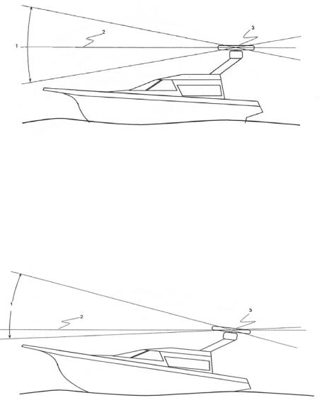
4.2 Power boat installations
Normally, you should install the scanner horizontally, to produce an equal sweep around the power boat:
However, when the power boat is traveling at high speed, the bow rises up out of the water and if the elevation angle (trim) of the bow is raised up so that it equals, or exceeds, 50% of the vertical beam width of the radar, this can cause two problems:
•ahead of the power boat, the beam is projected too high to sweep the water surface effectively. Targets can be missed completely or appear at a very poor resolution on the display screen.
•astern of the power boat, the beam is projected too low and is concentrated over a small area of water so that sea clutter becomes a problem on the display screen.
In this case, you're recommended to install the scanner so that is tilted down at the front, at an angle that will produce an almost horizontal sweep when the power boat is running at speed.
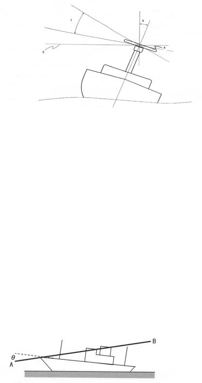
4.3 Yacht installations
Normally you should install the scanner horizontally, to produce an equal sweep around the yacht. However, a yacht heels over to the lee side, and when the heel angle exceeds 50% of the vertical beam width of the radar, this can cause two problems:
•on the windward side of the yacht, the beam is projected too high to sweep the water surface effectively. Targets can be missed completely or appear at very poor resolution on the display unit.
•on the lee side of the yacht, the beam is projected too low and is concentrated over a small area of water so that sea clutter becomes a problem on the display unit.
In this case, you're recommended to install the scanner on a gimbal mounting so that it can operate effectively in a heavy swell or when the yacht is heeled over.
4.4 How to find the optimum height for the scanner
The optimum height for the scanner is as close as possible to the A-B line for best performance. How to find the A-B Line:
The vertical extent of the radar beam is 2θ°, so most of the radar beam is concentrated within this angle, meaning that outside of this angle the radar beam will be very weak.
Scanner model |
θ° value (half the -3 dB beam |
|
width) |
2 kW |
15 |
|
|
4 kW |
12.5 |
|
|
6 kW |
10 |
|
|
10 kW |
10 |
|
|
25 kW |
10 |
|
|
An example of an A-B Line is shown in the picture. If you install the scanner below the A-B line, the scanner will be too low. It will be difficult to acquire distant targets and the superstructure will be more likely to impede the passage of the beam and generate false echoes. If the scanner is installed too high above the A-B line, the beam will miss close targets and increase sea clutter return.

You can find the A-B line for any vessel as follows:
•Using a drawing of the vessel, lay a rule along the line of the main deck and continue this forwards as a dashed line extending beyond the bow.
•Using a protractor, measure the θ° value (for your scanner model) below the dashed line at the bow and draw in a new line along this angle.
•Extend the new line back beyond the bow of the vessel. This is the A-B line.
4.5 How to find the theoretical maximum detection range
Propagation of the radar beam can vary, depending on the properties of the air through which it's traveling. Under normal conditions, the distance that the radar beam travels is approximately 10% further than the distance to the optical horizon.
You can calculate the theoretical distance traveled by the radar beam using the following formula: D = 2.23 (√h1 + √h2)
where:
•D is distance traveled by the radar beam
•h1 is the height above sea level of the scanner
•h2 is the height above sea level of a target
An example is shown below:
In this example, the scanner is installed on the vessel at a height of 10 ft (3 m) above sea level (h1). Island A is 33 ft (10 m) high (h2) and for comparison, Island B is 16.4 ft (5 m) high (h2). Both islands are at a distance (D) of 10 nautical miles from the vessel.
Calculations using the formula show that, at this distance, the radar can only detect objects that are more than 25 ft (7.6 m) high, which means that Island A is shown on the radar but Island B is not shown.
Remember that:
•the maximum detection range of the radar is limited by the curvature of the Earth's surface under normal conditions of wave propagation.
•bad weather conditions can reduce the maximum detection range
4.6 How to reduce false echoes and shadow zones
False echoes can be produced on the radar display if the scanner is installed too close to an object on the vessel's superstructure. This object can block the radar beam and reflect it back, generating the false echoes and shadow zones.
If you're having problems with false echoes and/or shadow zones, check if it's possible to reinstall the scanner at a higher location where the radar beam will be clear of any obstructions.
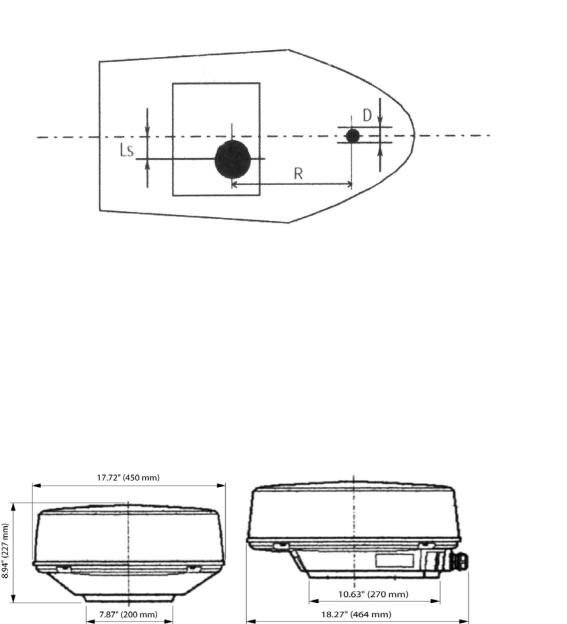
If not, try relocating the scanner away from the central keel line of the vessel to the starboard side. This will move any shadows to the port side, maximize the radar view of your give way sector, and ensure a clear view of the area around the vessel at the bow.
Use the following formula to calculate the distance that you'll need to move the scanner: Ls = 0.4R + D/2 (when R is less than 49 ft [15 m])
Ls = 0.025R + D/2 (When R is greater than or equal to 49 ft [15 m]) where:
Ls = distance to be moved from the keel line D = diameter of the obstacle
R = distance between the antenna and the obstacle
4.7 2 kW scanner dimensions
Before starting the installation, use the drilling template to identify the:
•cable inlet
•drill holes
•front and rear of the radome
•location of the drain hole (ensure that your chosen location allows the drain hole to empty).
The 2 kW scanner dimensions are shown:

4.8 Install a scanner on a trestle
Depending on your chosen location for the scanner, it may be easier to install the scanner if you fabricate a trestle (or radar mast) on which you can mount the scanner.
The trestle must be sturdy and secure, and capable of supporting the scanner in all weather conditions.
You are recommended to install the base of the trestle parallel to the water surface.
Orient the trestle so that the cable inlet on the scanner will face the stern, and so that the scanner can be mounted at the correct angle (as discussed in the "Power boat installation" section).
Make sure that the edges of the trestle won't trap water.
4.9 Install the 2 kW scanner unit
IMPORTANT: Remember that you must screw the bolts into place from the underside of the location site, because the shape of the dome prevents you from installing the bolts from the topside. Ensure that you can access the underside of the location site before drilling.
Find the paper installation template and tape it securely to the chosen location site. Before drilling, check that
•the location site is not more than 0.6" (15 mm) thick.
•you have oriented the template correctly so that the front of the scanner unit will face the front of the vessel.
•the location site allows the drain hole to empty.
Drill the four holes where shown to a maximum depth of 0.6" (15 mm) plus the drain hole. Remove the template then position a rubber washer over each hole on the scanner. Ensure that the slot in the rubber washer is aligned with the rib on the scanner.
Position the scanner carefully over the bolt holes so that they are aligned with the holes of the rubber washers and the drill holes.
Place a spring washer then a plain washer onto each bolt, as shown. Screw each bolt into each drill hole from the underside of the location site, and tighten securely with a 5.31" (135 mm) torque wrench.
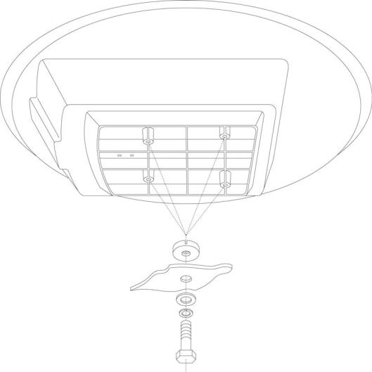
NOTE: Use the bolts supplied as these are hardened stainless steel and the correct length.
4.10 Install the radar processor
Install the radar processor in a dry location away from spray, rain, drips, and condensation.
The location site must allow you to easily connect the radar processor to the ship's ground, the interconnection cable, the power cable, and the radar communications cable or the network cable. Check that these cables and the ship's ground can easily reach the radar processor BEFORE you drill.
The radar processor dimensions are shown on the drilling template. Follow the instructions on the drilling template to install the radar processor.
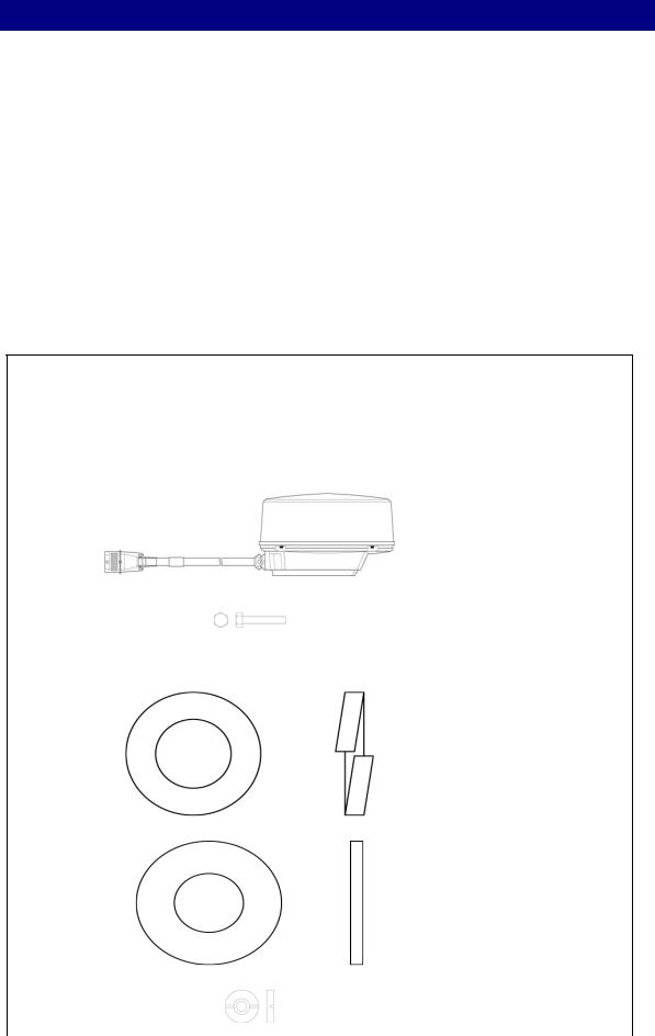
5 Check the 2 kW radar parts
The Navico 2 kW radar system consists of a scanner, a radar processor, and associated cables. some of which need to be ordered separately
There are two main for the 2 kW radar system:
•AA010024SIM (Simrad branded), AA010024NOR (Northstar branded),AA010024LOW (Lowrance branded) is the standard 2 kW radar system, consisting of a box containing the scanner and the 49 ft (15 m) interconnection cable (AA010088). This is pre-installed into the scanner. An optional 20 m (65.5 ft) AA01089 cable is available and will need installed by an experienced radar technician
•AA010012 is the radar processor. No inter connection cables are shipped with this item and have to be ordered separately See interconnection cables in the section relating to the display head unit
If you want to use an interconnection cable length other than the 15 m (49 ft) or 20 m (65.5 ft) options, please consult your Navico brand dealer.
Unpack the boxes carefully and check the contents against the packing lists. If anything is missing, contact your distributor.
AA010024SIM Simrad branded 2 kW scanner standard components AA010024NOR Northstar branded 2 kW scanner standard components AA010024LOW Lowrance branded 2 kW scanner standard components
Quantit |
Item |
Part name |
Part no. |
y |
|
|
|
1 |
|
Scanner unit |
AA010024xxx |
|
|
|
with |
|
|
|
interconnection |
|
|
|
cable |
|
|
|
(AA010088) |
|
|
|
15 m (49 ft) |
|
|
|
pre-installed |
|
|
|
|
4 |
|
Hexagonal |
Part of |
|
|
bolt 5/16-18 |
Hardware kit |
|
|
UNC x 31.75 |
HR000066 |
|
|
mm |
|
|
|
|
|
4 |
|
M8 Spring |
Part of |
|
|
washer |
Hardware kit |
|
|
|
HR000066 |
|
|
|
|
4 |
|
M8 Plain |
Part of |
|
|
washer |
Hardware kit |
|
|
|
HR000066 |
|
|
|
|
4 |
|
Rubber |
Part of |
|
|
washer |
Hardware kit |
|
|
|
HR000066 |
|
|
|
|
1 |
|
Packing list |
LA000450 |
|
|
|
|
1 |
|
Installation |
LA000410 |
|
|
sheet |
|
|
|
MTZ303386 |
|
|
|
|
|
1 |
|
Mounting |
LA000451 |
|
|
template |
|
|
|
|
|
AA010012 2 kW Radar processor standard components
Qnt |
Item |
Description |
Part No |
1 |
|
2 kw Radar |
AA010012 |
|
|
processor |
|
|
|
|
|
1 |
|
This Manual |
|
|
|
|
|
1 |
|
Installation |
LA000276 |
|
|
Template |
|
|
|
|
|
1 |
|
Product |
CD000085 |
|
|
Registration |
|
|
|
Card |
|
|
|
|
|
1 |
|
Warranty |
CD000260 |
|
|
Card |
|
|
|
|
|
4 |
|
Mounting |
HR000061 |
|
|
Screws |
|
|
|
|
|

AA010089 Optional longer length interconnection cable for radar scanner - order separately
Quantit |
Item |
Part name |
Part No |
y |
|
|
|
1 |
|
Interconnectio |
AA01089 |
|
|
n cable for the |
length 65.5 ft |
|
|
radar scanner |
(20 m) |
|
|
|
|
 Loading...