


 Loading...
Installation manual
Simrad SX95
Hull unit
www.simrad.com
T E C H N O L O G Y F O R S U S T A I N A B L E F I S H E R I E S
Simrad SX95
Installation manual
This document provides the necessary information of how to install the Simrad SX95 Hull Unit.
For the remaining sonar installation and setup procedures, refer to the Simrad SX90 Installation manual.
The information provided in this manual must be regarded as general guidelines and recommendations. The installation shipyard must design and manufacture installation hardware to fit the Simrad SX95 Hull Unit on each individual vessel.
319568/B 14 May 2008

Document history
Document number: 319568
Rev.A |
18 April 2008 |
First version. |
|
|
|
|
|
Rev.B |
14 May 2008 |
Information added to drawing 322202. See SX95 Mounting trunk |
|
outline dimensions on page 56. |
|||
|
|
Copyright
©2008 Kongsberg Maritime AS
The information contained in this document remains the sole property of Kongsberg Maritime AS. No part of this document may be copied or reproduced in any form or by any means, and the information contained within it is not to be communicated to a third party, without the prior written consent of Kongsberg Maritime AS. The document, or any part of it, may not be translated to any other language without the written approval from Kongsberg Maritime AS.
Disclaimer
Kongsberg Maritime AS endeavours to ensure that all information in this document is correct and fairly stated, but does not accept liability for any errors or omissions.
Warning
The equipment to which this manual applies must only be used for the purpose for which it was designed. Improper use or maintenance may cause damage to the equipment and/or injury to personnel. The user must be familiar with the contents of the appropriate manuals before attempting to install, operate or work on the equipment.
Kongsberg Maritime AS disclaims any responsibility for damage or injury caused by improper installation, use or maintenance of the equipment.
Support
If you require maintenance on your Simrad SX95 Hull Unit, contact your local dealer. You can also contact us using the following address: simrad.support@simrad.com. If you need information about our other products, visit www.simrad.com. On our web site you will also find a list of our dealers and distributors.
Simrad
Kongsberg Maritime AS |
Telephone: +47 33 03 40 00 |
|
Strandpromenaden 50 |
Telefax: +47 33 04 29 87 |
|
P.O.Box 111 |
www.simrad.com |
|
|
||
N-3191 Horten, Norway |
simrad.sales@simrad.com |
|

Installation manual
Table of contents |
|
ABOUT THIS MANUAL ....................................................... |
7 |
SIMRAD SX95 HULL UNIT ................................................. |
9 |
Hull unit familiarization ......................................................................................... |
10 |
Hull unit main parts................................................................................................ |
11 |
Hull unit models overview ..................................................................................... |
12 |
Technical specifications.......................................................................................... |
13 |
Power specifications.................................................................................... |
13 |
Weights and dimensions, hull unit................................................................ |
13 |
Weights and dimensions, mounting trunk ..................................................... |
13 |
Environmental specifications ....................................................................... |
14 |
INSTALLATION PLANNING.............................................. |
15 |
Location of the hull unit ......................................................................................... |
16 |
Sonar room requirements ....................................................................................... |
17 |
Sonar room physical properties.................................................................... |
17 |
Sonar room environmental requirements ...................................................... |
18 |
Sonar room electrical requirements .............................................................. |
19 |
Sonar room special requirements ................................................................. |
19 |
Sonar room arrangement example.......................................................................... |
20 |
SONAR TRUNK INSTALLATION........................................ |
22 |
Mounting the sonar trunk ....................................................................................... |
23 |
Sonar trunk protection ............................................................................................ |
24 |
Sonar trunk installation principles.......................................................................... |
24 |
Sonar trunk installation measurements................................................................... |
27 |
HULL UNIT INSTALLATION ............................................. |
28 |
How to unpack the hull unit from its transport box ............................................... |
29 |
Hull unit mounting ................................................................................................. |
30 |
Bleeding air cock.................................................................................................... |
31 |
Mechanical support ................................................................................................ |
32 |
Transducer alignment ............................................................................................. |
32 |
Hull unit installation check list............................................................................... |
33 |
CABLE LAYOUT AND INSTALLATION ............................... |
34 |
Cable plan............................................................................................................... |
35 |
Cabling principles................................................................................................... |
36 |
Cable procedures .................................................................................................... |
37 |
AC mains to Motor Control Unit (C06) ........................................................ |
38 |
Transceiver Unit to Motor Control Unit (C32) .............................................. |
39 |
Transducer cable (C35) ............................................................................... |
40 |
319568/B |
3 |

Simrad SX95
|
START-UP PROCEDURES ................................................. |
41 |
|
Starting up the Hull Unit ........................................................................................ |
41 |
|
Hull unit familiarization .............................................................................. |
42 |
|
Motor Control Unit familiarization............................................................... |
43 |
|
Functional check......................................................................................... |
44 |
|
Apply 3-phase AC power ............................................................................ |
45 |
|
Check hoist motor’s 3–phase AC connections............................................... |
46 |
|
Check the 3–phase connection for correct rotation direction........................... |
47 |
|
Check the contactor operation...................................................................... |
48 |
|
Functional check with hoist and lower operations ......................................... |
49 |
|
Alignment and offset adjustments .......................................................................... |
51 |
|
Alignment of the sonar picture..................................................................... |
51 |
|
Adjusting the stabilisation sensor offset........................................................ |
52 |
|
DRAWING FILE ............................................................... |
54 |
|
SX95 Hull unit outline dimensions ........................................................................ |
55 |
|
SX95 Mounting trunk outline dimensions ............................................................. |
56 |
|
SX95 Mounting trunk production .......................................................................... |
57 |
|
Blind cover for sonar trunk .................................................................................... |
58 |
A |
CABLE DETAILS............................................................... |
59 |
|
Detailed list of cables ............................................................................................. |
59 |
|
SX90/C06 AC mains to Motor Control Unit ................................................. |
59 |
|
SX90/C32 Transceiver to Motor Control ethernet.......................................... |
59 |
|
SX90/C35 Transducer cable ........................................................................ |
59 |
|
Cable specifications................................................................................................ |
60 |
|
AC mains cable to Motor Control Unit ......................................................... |
61 |
|
Ethernet cable with RJ45, “straight”............................................................. |
62 |
|
Cable connections................................................................................................... |
63 |
|
Motor Control Unit connections................................................................... |
64 |
|
Transceiver Unit connections....................................................................... |
65 |
B |
BASIC CABLE REQUIREMENTS ........................................ |
66 |
|
Cable trays.............................................................................................................. |
66 |
|
Radio Frequency interference ................................................................................ |
67 |
|
Physical protection ................................................................................................. |
67 |
|
Grounding............................................................................................................... |
67 |
|
Cable connections................................................................................................... |
68 |
|
Cable terminations.................................................................................................. |
68 |
|
Cable identification................................................................................................. |
68 |
C |
EQUIPMENT HANDLING .................................................. |
69 |
|
Transportation......................................................................................................... |
69 |
|
Lifting..................................................................................................................... |
69 |
|
Storage prior to installation or use ......................................................................... |
70 |
4 |
319568/B |

Installation manual
Inspection ............................................................................................................... |
71 |
Unpacking .............................................................................................................. |
72 |
General unpacking procedure ...................................................................... |
72 |
Unpacking electronic and electromechanical units ........................................ |
72 |
Unpacking mechanical units ........................................................................ |
73 |
Unpacking transducers ................................................................................ |
73 |
Storage after unpacking.......................................................................................... |
73 |
Storage after use ..................................................................................................... |
74 |
Cleaning cabinets........................................................................................ |
74 |
Mechanical units......................................................................................... |
74 |
Cables........................................................................................................ |
75 |
Internal batteries ......................................................................................... |
75 |
Dehumidifier .............................................................................................. |
76 |
Coatings..................................................................................................... |
76 |
Re-packaging.......................................................................................................... |
76 |
Temperature protection........................................................................................... |
76 |
Circuit board handling and packaging.................................................................... |
77 |
Beware of ESD!.......................................................................................... |
77 |
Unpacking and handling circuit boards......................................................... |
77 |
Unpacking on board.................................................................................... |
77 |
Returning a circuit board ............................................................................. |
78 |
What is ESD? ......................................................................................................... |
78 |
319568/B |
5 |

Simrad SX95
6 |
319568/B |

About this manual
ABOUT THIS MANUAL
Purpose
The purpose of this manual is to provide the information and procedures required for installation of the Simrad SX95 Hull unit.
Note
This manual only describes the installation of the hull unit. For the remaining sonar installation and setup procedures, refer to the Simrad SX90 Installation manual.
About these instructions
The manual is intended for technical personnel, engineers and naval architects. It is assumed that the personnel is conversant with the general principles of sonar installation and operation.
These instructions must be followed carefully to ensure optimal sonar performance. As a guide, installation procedures are presented in the order they are to be performed. Successful completion of each procedure is to be confirmed by checking off the corresponding box. After installation, this document should be stored on board the vessel for later reference when updating or servicing the equipment. The manual also defines the equipment responsibility, and provides instructions for unpacking and storage.
Installation drawings
Detailed vessel specific mechanical drawings for the installation must be provided by the customer, or any shipyard contracted to perform the installation. Simrad may, on special order, provide assistance to these drawings. Drawings must be approved by the appropriate vessel certification authority prior to installation of the system.
Note
The installation instructions given in this document must be adhered to. Failure to do so may render the guarantee void.
Kongsberg Maritime AS will accept no responsibility for any damage or injury to the system, vessel or personnel caused by equipment that has been incorrectly installed or maintained, or by drawings, instructions or procedures that have not been prepared by us.
319568/B |
7 |

Simrad SX95
References
Refer to the following manuals for additional information about the Simrad SX90 sonar system. Order numbers in brackets. All documents can be downloaded from our web site http://www.simrad.com.
•SX90 Installation Manual [307531]
•SX90 Operator Manual [307672]
•SX90 Reference Manual [307670]
8 |
319568/B |
Simrad SX95 Hull Unit
SIMRAD SX95 HULL UNIT
This chapter offers an introduction to the main parts and technical specifications of the Simrad SX95 hull unit.
Topics
•Hull unit familiarization on page 10
•Hull unit main parts on page 11
•Hull unit models overview on page 12
•Technical specifications on page 13
319568/B |
9 |

Simrad SX95
Hull unit familiarization
Figure 1 Hull unit familiarization
A
B |
J |
|
|
C |
|
D |
|
E |
K |
|
L |
F |
|
G |
|
H |
M |
I
(CD015414-003)
(A)Hand crank
(B)Identification label
(C)Hoisting motor
(D)Motor Control Unit
(E)Hoisting unit
(F)Transducer shaft sleeve
(G)Mounting flange
(H)Mounting trunk
(I)Transducer
(J)Transducer cable
(K)Transducer shaft
(L)Air bleeding cock
(M)Zinc anodes
10 |
319568/B |

Simrad SX95 Hull Unit
Hull unit main parts
The hull unit is located in the sonar room, close to the transceiver. It is mounted on a mounting trunk, which accommodates the transducer when the sonar is switched off. As the transducer shaft penetrates the ship’s hull, it is required that all personnel handling installation and service are familiar with the hull unit’s main parts and operational principles.
AThe hand crank is used for manual hoisting and lowering of the transducer shaft. When not in use, the hand crank is stored inside the Motor Control Unit.
BThe identification label provides the hull unit’s name, as well as its registrationand serial numbers.
CThe hoisting motor is used to lower and hoist the transducer shaft. In order to rotate in both directions, the motor is powered by a 3-phase voltage. The motor is controlled by the Motor Control Unit.
DThe Motor Control Unit controls the hoisting motor. It also contains the sensor required for sonar beam stabilization.
EThe hoisting unit performs the hoisting and lowering of the transducer by converting the rotary motion from the motor to a vertical linear motion for the transducer shaft.
FThe transducer shaft sleeve supports the transducer shaft and ensures that the assembly is water tight. The area between the upper and lower bearings is also used as a grease reservoir for the lubrication of the bearings and for additional water tightening.
GThe mounting flange provides mechanical fastening of the hull unit to the mounting trunk. A gasket is used to make the assembly watertight.
HThe mounting trunk accommodates the transducer when the transducer is retracted.
Note
The trunk is not included in the standard delivery of the sonar, but can be ordered as an option.
IThe transducer has a cylindrical shape. It contains 256 separate wide-band transducer elements.
JThe transducer cable contains two wires for each transducer element. All are housed in a flexible hose which ends up in a plug unit for connection to the Transceiver Unit.
KThe transducer shaft penetrates the shaft sleeve, and allows the transducer to be lowered and hoisted. The transducer is connected to the lower end of the transducer shaft using a special plug.
319568/B |
11 |
Simrad SX95
LThe air bleeding cock is provided to avoid air inside the trunk. We recommend that a pipe is connected to this cock with continuous rise to the main deck or through the vessel side.
MA number of zinc anodes are mounted below the mounting flange to prevent corrosion on the transducer shaft.
Hull unit models overview
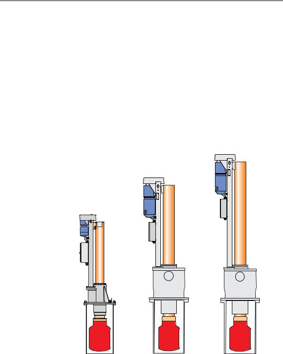
The Simrad SX90 sonar may be delivered with any one of several different hull unit models.
Figure 2 SX90 Hull unit models
(CD015401-001) |
|
SX90 |
SX91 |
SX95 |
SX92 |
SX93 |
•SX90: This hull unit has 1.2 m stroke length, and it is designed for maximum speed 24 knots. It will fit on a standard Simrad trunk with 620 mm pitch centre diameter (PCD).
•SX91: This hull unit has 1.6 m stroke length, and it is designed for maximum speed 20 knots. It will fit on a standard Simrad trunk with 620 mm pitch centre diameter (PCD).
•SX92: This is the "standard" hull unit for the SX90 sonar. It has 1.2 m stroke length, and it is designed for maximum speed 24 knots. It will fit on a standard Simrad trunk with 680 mm pitch centre diameter.
12 |
319568/B |

Simrad SX95 Hull Unit
•SX93: This hull unit has 1.6 m stroke length, and it is designed for maximum speed 20 knots. It will fit on a standard Simrad trunk with 680 mm pitch centre diameter.
•SX95: This hull unit has 1.0 m stroke length, and it is designed for maximum speed 12 knots. It will fit on a standard Simrad trunk with 540 mm pitch centre diameter.
Technical specifications
This section provides the basic technical specifications for the Simrad SX95 Hull Unit.
Note
We are engaged in continuous development of our products and reserves the right to alter specifications without prior notice.
Power specifications
•Voltage:
–Nominal: 230 / 380 / 440 Vac, 3-phase (selectable)
–Deviation, 230 Vac: 15 % of nominal voltage
–Deviation, 380/440 Vac: 340 to 485 Vac
–Transient: 20 % of nominal voltage, recover time 3 s
•Power consumption: 1100 VA
•Frequency: 47 to 63 Hz
Weights and dimensions, hull unit
•Weight: Approximately 500 kg
•Dimensions:
– SX95 Hull unit outline dimensions on page 55
Weights and dimensions, mounting trunk
•Weight: Approximately 68 kg
•Height: 990 mm
•Flange diameter: 580 mm
•Trunk diameter: 508 mm
•Drawing:
–SX95 Mounting trunk outline dimensions on page 56
–SX95 Mounting trunk production on page 57
–Blind cover for sonar trunk on page 58
319568/B |
13 |

Simrad SX95
Environmental specifications
•Operational temperature: 0 to +40°C
•Storage temperature: -40 to +70°C
•Humidity: 5 to 95% non-condensing
14 |
319568/B |

Installation planning
INSTALLATION PLANNING
Note
For installation in a previously installed trunk system, first read the information about sonar room requirements. Then proceed to the Hull Unit installation description.
This chapter provides the marine engineers responsible the information necessary to plan and install the sonar’s hull unit according to Simrad’s requirements. Correct installation of the sonar transducer is vital to the system’s performance. Several variables must be taken into consideration, the most important of which is the vessel’s construction. This guide is for use in selecting the best location for the transducer and includes a brief description of areas to be avoided.
Note
All installation drawings must be supplied by the shipyard. The installation must be approved by the vessel’s national registry and corresponding maritime authority and/or classification society. The shipowner and shipyard performing the installation are responsible for obtaining and paying for installation approval.
Simrad offers free advice for installation planning. Proposed arrangements may be sent for commentary or suggestions supplied by Simrad. The following drawings should be submitted should assistance be requested:
•General arrangement
•Body plan and drawings of relevant bottom tanks and cofferdams
•Lines plan
Topics
•Location of the hull unit on page 16
•Sonar room requirements on page 17
•Sonar room arrangement example on page 20
319568/B |
15 |
Simrad SX95
Location of the hull unit
Fore and aft
The hull unit should preferably be located within 1/3 to 1/10 of the vessel’s Length Between Perpendiculars (LBP) from its
Forward Perpendicular (FP). Deviations should not be made without consulting Simrad.
Athwartships
The hull unit may be located on the Centre Line (CL) of the vessel, or alongside its keel. If the installation is offset from the vessel’s centre line, make sure that transducer transmission and reception will not be obstructed by the keel.
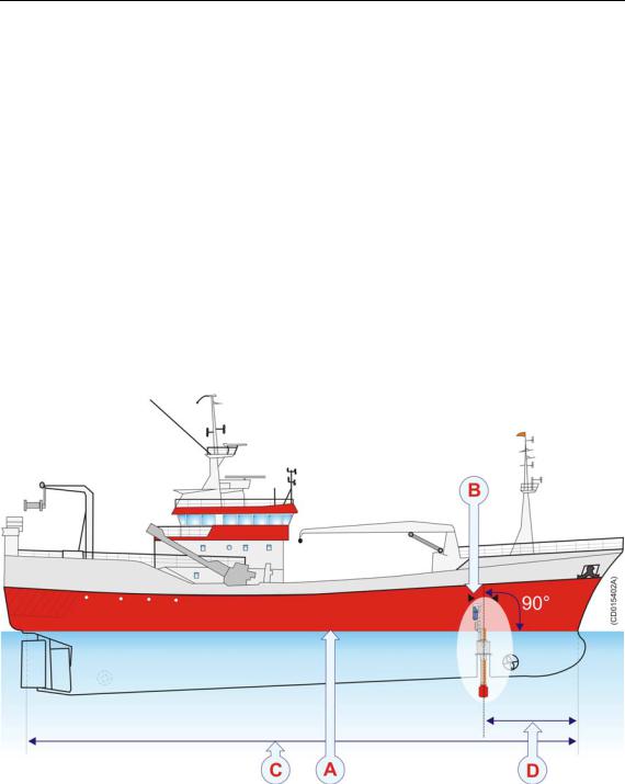
Figure 3 Location of the hull unit
AWater level at normal trim
BWelding marks to indicate hull unit location when docking
CLength Between Perpendiculars (LBP)
D1/3 to 1/10 of LBP
Important considerations related to noise
The installation trunk must be installed so that it will remain vertical under normal operating conditions. The primary sources of underwater disturbance (other than a vessel’s main propeller and bow/stern thruster) that affect transducer reception are:
16 |
319568/B |

Installation planning
•Main or bilge keels
•Zinc anodes
•Cooling elements protruding from the hull
•Equipment such as sonar transducers and pilot tubes
•Sea chests
•Overboard discharges
•Dents in the hull
All appendages to the hull, indentations and pipe in/outlets are potential sources of underwater noise. They may act as resonant cavities amplifying noise at certain frequencies, create cavitation or turbulence. Transducers should not be located in the vicinity of such objects and especially not immediately aft of them.
Sonar room requirements
It is strongly recommended to use a dedicated compartment to house the hull unit and sonar transceiver unit. These two units must also be installed relatively close to each other due to the limited length of the transducer cables. Observe these minimum sonar room requirements to obtain suitable working conditions for sonar installation, use and maintenance.
Sonar room physical properties
The following physical properties must be taken into consideration when the sonar room is planned:
•Size
•Access hatches
•Lifting
•Deck
Size
The sonar room must be dimensioned to house both the hull unit and the transceiver unit. This is due to the limited length of the flexible hose protected cabling (approximately 3.5 m) connecting these two units. A well designed sonar room reduces the risk of corrosion and simplifies maintenance increasing system reliability. The sonar room should not be unnecessarily obstructed by girders, pipes etc. which might cause installation problems or impede maintenance.
Access hatches
The sonar room must be accessible under all conditions at sea or at a berth. All doors or hatches should be designed so that the equipment can be removed without being disassembled.
319568/B |
17 |

Simrad SX95
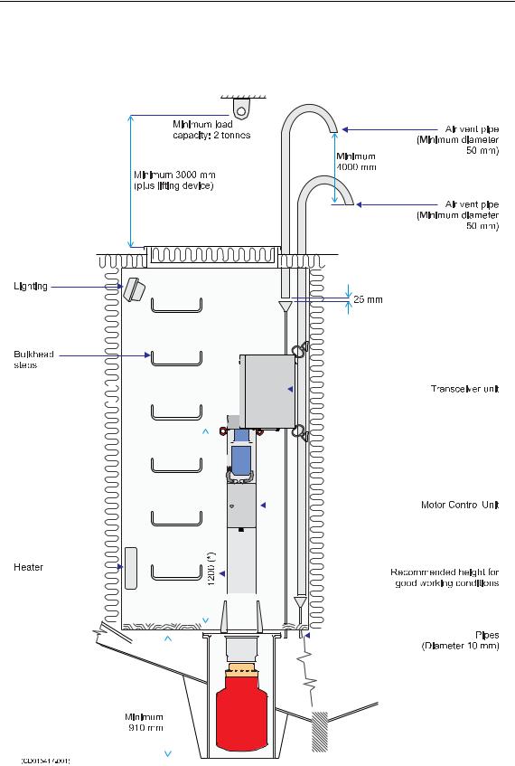
Lifting device
An attachment point, rated at a minimum of two -2- tons, for supporting a lifting device should be located above the hull unit. This permanently installed fixture will facilitate installation trunk and hull unit mounting, and also may be used for future equipment maintenance or replacement.
Deck
Once the installation has been completed, the sonar room should be suitably decked without restricting access to the equipment.
Sonar room environmental requirements
The following environmental properties must be taken into consideration when the sonar room is planned:
•Heating
•Insulation
•Ventilation
Heating
The sonar room should be equipped with heater, dimensioned to maintain the equipment within its environmental tolerances (at least 1000 W), installed close to the deck. Heating is also an effective method for reducing humidity.
Insulation
Bulkheads must be insulated and provided with an interior wall to the deck. The insulation should be the minimum equivalent of 50 mm of rock-wool. In addition, piping passing through the space prone to condensation must be insulated.
Ventilation
The sonar room should be connected to the vessel’s ventilation system. If this is not possible, two 3-inch vents must be provided from the sonar room to the main deck. In the sonar room, the air inlet should be located in close to the deck and the outlet as high as possible. A funnel shaped drip-collector should be mounted below the vent pipes to divert moisture to the bilge.
On the main deck, the best ventilation is provided when the outlet pipe is at least four meters higher than the inlet pipe. To keep out sea water, rain and spray, the ventilation pipes should be fitted with goosenecks of the equivalent.
18 |
319568/B |
Installation planning
Sonar room electrical requirements
The following electrical requirements must be taken into consideration when the sonar room is planned:
•Conduit
•Bilge pump
•Lights
Conduit
If the cable between the wheelhouse and the sonar room passes through hatches or areas where it may be damaged, it should be run through a conduit (two inch conduit is recommended).
Bilge pump
The sonar room should be connected to the vessel’s bilge pump system. If this is not possible, a separate bilge pump for the sonar room must be installed.
Lights
The sonar room should be equipped with suitable lighting to simplify the installation and aid future maintenance.
Sonar room special requirements
The following special requirements must be taken into consideration when the sonar room is planned:
•Air vent pipe
•Precautions for dry docking
Air vent pipe
An air vent conduit with a minimum of 10 mm internal diameter must be attached to the air bleeding cock on the hull unit. The pipe should be laid with continuous rise to free air on deck or through the ship’s side.
Note
Through-hull modifications are subject to approval by the vessel’s national registry and corresponding maritime authority. The shipowner and shipyard are responsible for obtaining installation approval.
Precautions for dry docking
Make sure that ample space is provided between the vessel and dry dock for system installation.
To facilitate future dry docking, mark the position of the installed trunk on the ship drawings as well as on the hull.
319568/B |
19 |
Simrad SX95
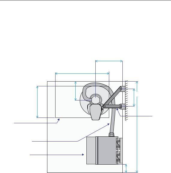
Sonar room arrangement example
These drawings illustrate a typical sonar room with ample space for hull unit, transceiver unit and personnel.
Figure 4 Sonar room arrangement example, top view
|
|
500 mm (*) |
|
1000 mm (*) |
|
|
400 mm (*) |
300 mm (*) |
|
|
|
600 mm (*) |
|
|
|
|
Removable |
|
|
supports |
|
|
brackets |
Hatch |
|
|
(Minimum size |
|
|
550 x 1000 mm) |
|
|
Transducer cable |
|
|
(Total length 3.5 m) |
|
Maximum |
|
|
1000 mm |
Transceiver Unit |
|
|
(CD015417-002) |
(*) = Recommended minimum |
150 mm (*) |
20 |
319568/B |
Installation planning
Figure 5 Sonar room arrangement example, side view
|
|
|
|
|
|
|
|
|
|
|
|
|
|
|
|
|
|
|
|
|
|
|
|
|
|
|
|
|
|
|
|
|
|
|
|
|
|
|
|
|
|
|
|
|
|
|
|
|
|
|
|
|
|
|
|
|
|
|
|
|
|
|
|
|
|
|
|
|
|
|
|
|
|
|
|
|
|
|
|
|
|
|
|
|
|
|
|
|
|
|
|
|
|
|
|
|
|
|
|
|
|
|
|
|
|
|
|
|
|
|
|
|
|
|
|
|
|
|
|
|
|
|
|
|
|
|
|
|
|
|
|
|
|
|
|
|
|
|
|
|
|
|
|
|
|
|
|
|
|
|
|
|
|
|
|
|
|
|
|
|
|
|
|
|
|
|
|
|
|
|
|
|
|
|
|
|
|
|
|
|
|
|
|
|
|
|
|
|
|
|
|
|
|
|
|
|
|
|
|
|
|
|
|
|
|
|
|
|
|
|
|
|
|
|
|
|
|
|
|
|
|
|
|
|
|
|
|
|
|
|
|
|
|
|
|
|
|
|
|
|
|
|
|
|
|
|
|
|
|
|
|
|
|
|
|
|
|
|
|
|
|
|
|
|
|
|
|
|
|
|
|
|
|
|
|
|
|
|
|
|
|
|
|
|
|
|
|
|
|
|
|
|
|
|
|
|
|
|
|
|
|
|
|
|
|
|
|
|
|
|
|
|
|
|
|
|
|
|
|
|
|
|
|
|
|
|
|
|
|
|
|
|
|
|
|
|
|
|
|
|
|
|
|
|
|
|
|
|
|
|
|
|
|
|
|
|
|
|
|
|
|
|
|
|
|
|
|
|
|
|
|
|
|
|
|
|
|
|
|
|
|
|
|
|
|
|
|
|
|
|
|
|
|
|
|
|
|
|
|
|
|
|
|
|
|
|
|
|
|
|
|
|
|
|
|
|
|
|
|
|
|
|
|
|
|
|
|
|
|
|
|
|
|
|
|
|
|
|
|
|
|
|
|
|
|
|
|
|
|
|
|
|
|
|
|
|
|
|
|
|
|
|
|
|
|
|
|
|
|
|
|
|
|
|
|
|
|
|
|
|
|
|
|
|
|
|
|
|
|
|
|
|
|
|
|
|
|
|
|
|
|
|
|
|
|
|
|
|
|
|
|
|
|
|
|
|
|
|
|
|
|
|
|
|
|
|
|
|
|
|
|
|
|
|
|
|
|
|
|
|
|
|
|
|
|
|
|
|
|
|
|
|
|
|
|
|
|
|
|
|
|
|
|
|
|
|
|
|
|
|
|
|
|
|
|
|
|
|
|
|
|
|
|
|
|
|
|
|
|
|
|
|
|
|
|
|
|
|
|
|
|
|
|
|
|
|
|
|
|
|
|
|
|
|
|
|
|
|
|
|
|
|
|
|
|
|
|
|
|
|
|
|
|
|
|
|
|
|
|
|
|
|
|
|
|
|
|
|
|
|
|
|
|
|
|
|
|
|
|
|
|
|
|
|
|
|
|
|
|
|
|
|
|
|
|
|
|
|
|
|
|
|
|
|
|
|
|
|
|
|
|
|
|
|
|
|
|
|
|
|
|
|
|
|
|
|
|
|
|
|
|
|
|
|
|
|
|
|
|
|
|
|
|
|
|
|
|
|
|
|
|
|
|
|
|
|
|
|
|
|
|
|
|
|
|
|
|
|
|
|
|
|
|
|
|
|
|
|
|
|
|
|
|
|
|
|
|
|
|
|
|
|
|
|
|
|
|
|
|
|
|
|
|
|
|
|
|
|
|
|
|
|
|
|
|
|
|
|
|
|
|
|
|
|
|
|
|
|
|
|
|
|
|
|
|
|
|
|
|
|
|
|
|
|
|
|
|
|
|
|
|
|
|
|
|
|
|
|
|
|
|
|
|
|
|
|
|
|
|
|
|
|
|
|
|
|
|
|
|
|
|
|
|
|
|
|
|
|
|
|
|
|
|
|
|
|
|
|
|
|
|
|
|
|
|
|
|
|
|
|
|
|
|
|
|
|
|
|
|
|
|
|
|
|
|
|
|
|
|
|
|
|
|
|
|
|
|
|
|
|
|
|
|
|
|
|
|
|
|
|
|
|
|
|
|
|
|
|
|
|
|
|
|
|
|
|
|
|
|
|
|
|
|
|
|
|
|
|
|
|
|
|
|
|
|
|
|
|
|
|
|
|
|
|
|
|
|
|
|
|
|
|
|
|
|
|
|
|
|
|
|
|
|
|
|
|
|
|
|
|
|
|
|
|
|
|
|
|
|
|
|
|
|
|
|
|
|
|
|
|
|
|
|
|
|
|
|
|
|
|
|
|
|
|
|
|
|
|
|
|
|
|
|
|
|
|
|
|
|
|
|
|
|
|
|
|
|
|
|
|
|
|
|
|
|
|
|
|
|
|
|
|
|
|
|
|
|
|
|
|
|
|
|
|
|
|
|
|
|
|
|
|
|
|
|
|
|
|
|
|
|
|
|
|
|
|
|
|
|
|
|
|
|
|
|
|
|
|
|
|
|
|
|
|
|
|
|
|
|
|
|
|
|
|
|
|
|
|
|
|
|
|
|
|
|
|
|
|
|
|
|
|
|
|
|
|
|
|
|
|
|
|
|
|
|
|
|
|
|
|
|
|
|
|
|
|
|
|
|
|
|
|
|
|
|
|
|
|
|
|
|
|
|
|
|
|
|
|
|
|
21 |
|||||||||||||||||||
319568/B |
||||||||||||||||||||||||||||||||||||

Simrad SX95
SONAR TRUNK INSTALLATION
The sonar trunk provides the physical foundation for the entire hull unit gantry. The trunk further penetrates the hull, and it is therefore a crucial part of the hull unit assembly. In order to ensure proper sonar operation, the location of the sonar trunk must be carefully selected.
A trunk with a blind cover – approved by Det norske Veritas (DnV) – can be ordered from Simrad as an optional delivery, or it may be manufactured by the installation shipyard based on the drawings in this manual and the properties of the hull.
Note
The installation shipyard must provide all necessary installation drawings, and if required, these must be approved by the applicable authorities.
Topics
•Mounting the sonar trunk on page 23
•Sonar trunk protection on page 24
•Sonar trunk installation principles on page 24
•Sonar trunk installation measurements on page 27
Hull unit installation drawings
•SX95 Hull unit outline dimensions on page 55
•SX95 Mounting trunk outline dimensions on page 56
•Blind cover for sonar trunk on page 58
•SX95 Mounting trunk production on page 57
22 |
319568/B |
Sonar trunk installation
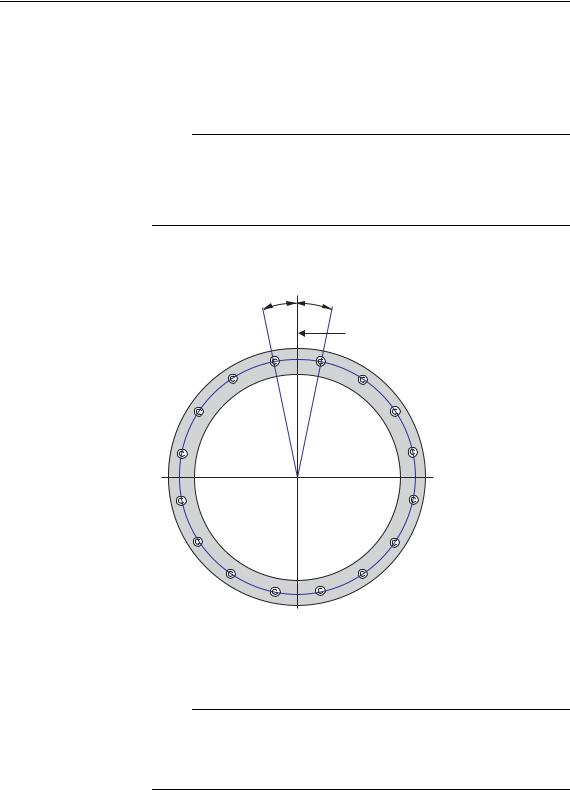
Mounting the sonar trunk
The location of the sonar trunk must be carefully selected.
Note
Note the orientation of the centre line of the trunk with regard to the mounting bolts.
Remove the gasket on the top flange during welding.
Figure 6 Orientation of the sonar trunk
|
1 |
|
Parallel to |
|
centre line |
|
(CD015415-003) |
The height from the top of the trunk flange to the underside of the protection blister must be selected as shown in the referenced figures.
Note
In order to obtain optimal sonar performance, the total height of the trunk must be as close as possible to its stated minimum height.
The top flange must be parallel to the construction waterline in both the fore-and-aft and athwartship directions.
The installation trunk must be welded to a doubling plate which must be at least 1.5 times as thick as the surrounding shell plating. The doubling plate’s final dimensions are to be governed by the
319568/B |
23 |

Simrad SX95
approved installation drawings supplied by the shipyard. The trunk must also be stiffened by welding knee-plates to it and the doubling plate in both the fore-and-aft and athwartship directions.
Sonar trunk protection
Protecting the blister
A steel blister must be fitted for protection. The blister shown is welded to the shell plating and then filled with oil to prevent corrosion. This method provides excellent protection and simplifies maintenance.
Corrosion protection
As soon as all installation, welding and grinding has been performed, the trunk and the surrounding area should be primed and painted using a quality protective coating.
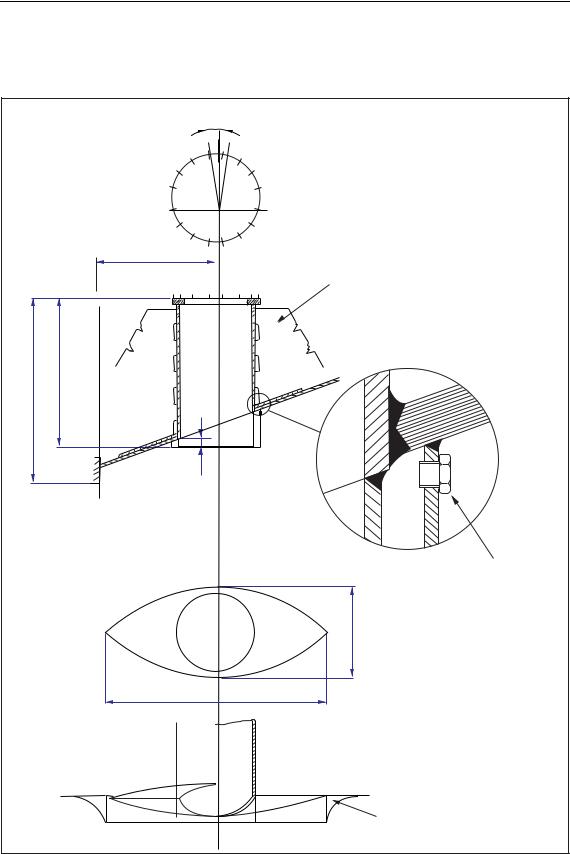
Sonar trunk installation principles
Observe the next two drawings, these illustrate the installation of the sonar trunk.
24 |
319568/B |
Sonar trunk installation
Figure 7 Installation of a trunk with open blister
|
A: As short as possible |
|
|
B: Max. 35 7/8" (910 mm) |
|
|
C: Min. 1 9/16" (40 mm) |
|
Fore-and-aft view |
D: Min. 35 7/8" (910 mm) |
|
E: Min. 22" (560 mm) |
||
|
|
A |
B |
D |
|
C |
3-4 knee-plates, must be welded to frames or floors
Bottom view
E
2.5-3xE
Side view
Plug for filling of oil
Thickness of plates
Knee-plates: 3/8" (10 mm) Blister and deflection bracket: 1/4" (6 mm)
The circular opening of the blister should have a diameter equal to the inside diameter of the trunk.
Deflection-brackets should be welded only to the shell-plating.
(CD015415-004)
319568/B |
25 |
Loading...