


SU90
Table of contents
 Loading...
Installation manual
Simrad SU90
Fish nding sonar
www.simrad.com
TECHNOLOGY FOR SUSTAINABLE FISHERIES


SimradSU90
Installationmanual
Thismanualprovidesyouwiththebasicinformation
requiredtoinstalltheSimradSU90Sonar.Forinformation
aboutthepracticaluseoftheproduct,refertotheSimrad
SU90OperatormanualortheSimradSU90Reference
manual.
AlluserdocumentationisincludedontheUSBmemory
devicethatisprovidedwiththeSimradSU90.Themanuals
canalsobedownloadedfromhttp://www.simrad.com/su90
WARNING:TheSimradSU90sonarmustneverbe
poweredupwhentheshipisindrydock.Thetransducer
willbedamagedifittransmitsinopenair.Toprevent
inadvertentuseofthesonar,pulloutthemainsplugon
theProcessorUnitwheneverthevesselisindrydock.
.
381293/A
2013-09-13
©
KongsbergMaritimeAS

Revisionstatus
Documentno:381293/V ersion:A/ISBN-13:978-82-8066-158-6
Rev.A2013–09–13
Firstversion
Copyright
©2013KongsbergMaritimeAS
TheinformationcontainedinthisdocumentremainsthesolepropertyofKongsbergMaritimeAS.Nopart
ofthisdocumentmaybecopiedorreproducedinanyformorbyanymeans,andtheinformationcontained
withinitisnottobecommunicatedtoathirdparty,withoutthepriorwrittenconsentofKongsberg
MaritimeAS.Thedocument,oranypartofit,maynotbetranslatedtoanyotherlanguagewithoutthe
writtenapprovalfromKongsbergMaritimeAS.
Disclaimer
KongsbergMaritimeASendeavourstoensurethatallinformationinthisdocumentiscorrectandfairly
stated,butdoesnotacceptliabilityforanyerrorsoromissions.
Warning
Theequipmenttowhichthismanualappliesmustonlybeusedforthepurposeforwhichitwas
designed.Improperuseormaintenancemaycausedamagetotheequipmentand/orinjury
topersonnel.Allusersmustbefamiliarwiththecontentsoftheappropriatemanualsbefore
attemptingtoinstall,operate,maintainorinanyotherwayworkontheequipment.
KongsbergMaritimeASdisclaimsanyresponsibilityfordamageorinjurycausedbyimproper
installation,useormaintenanceoftheequipment.
Supportinformation
Ifyourequiremaintenanceorrepair,contactyourlocaldealer.Youcanalsocontactususingthefollowing
address:simrad.support@simrad.com.Ifyouneedinformationaboutourotherproducts,visithttp:
//www.simrad.com.Onthiswebsiteyouwillalsondalistofourdealersanddistributors.
SeealsoSupportinformationonpage33.
KongsbergMaritimeAS
www.kongsberg.com

Installationmanual
Tableofcontents
ABOUTTHISMANUAL.....................................................13
SIMRADSU90.................................................................15
Systemdescription.................................................................................................16
Systemdiagram......................................................................................................18
Systemunits...........................................................................................................19
Colourdisplay............................................................................................19
ProcessorUnit............................................................................................19
OperatingPanel..........................................................................................19
OperatingPanelpowersupply.....................................................................20
Audioamplierwithloudspeakers...............................................................20
TransceiverUnit.........................................................................................20
HullUnit....................................................................................................20
Transducer.................................................................................................21
Scopeofsupply......................................................................................................21
Mainunitsincludedwiththestandarddelivery.............................................21
Additionalitems.........................................................................................22
Additionalrequireditems.......................................................................................22
Colourdisplay............................................................................................22
UninterruptedPowerSupply(UPS)..............................................................23
Installationtrunk.........................................................................................23
Speedlog...................................................................................................24
Coursegyro................................................................................................24
Optionalitems........................................................................................................25
Hullunit.....................................................................................................25
Installationtrunk.........................................................................................25
Extendedrange...........................................................................................26
Scienticinterface......................................................................................26
Otherperipheralequipment.........................................................................26
Audiooutput..............................................................................................28
Externalmotionreferenceunit(MRU).........................................................30
SecondaryOperatingPanel..........................................................................30
Generalsupplyconditions......................................................................................31
Equipmentresponsibility.............................................................................31
Receipt,unpackingandstorage....................................................................31
Generalinstallationrequirements...........................................................................32
Supplypower.............................................................................................32
UninterruptedPowerSupply(UPS)..............................................................32
Wiring........................................................................................................32
Compassdeviation......................................................................................33
381293/A
3

SimradSU90
Noisesources.............................................................................................33
Drydocking...............................................................................................33
Approvalbyclassicationsociety................................................................33
Supportinformation...............................................................................................33
INSTALLATIONPROCEDURE...........................................35
PREPARATIONS..............................................................37
Installationdrawings..............................................................................................38
Necessarytoolsandequipment..............................................................................38
Workerskills...........................................................................................................39
Determingthelocationofthehullunit..................................................................40
Foreandaftlocation...................................................................................40
Athwartshipslocation..................................................................................41
Importantconsiderationsrelatedtonoise......................................................41
Sonarroomrequirements.......................................................................................42
Watertightintegrity.....................................................................................42
Sizeandaccess...........................................................................................43
Heating......................................................................................................43
Insulation...................................................................................................43
Ventilation..................................................................................................43
Cableprotection.........................................................................................44
Electricalinstallationsandlights..................................................................44
Bilgepumpanddecking..............................................................................44
Liftingdevice.............................................................................................44
Communication..........................................................................................44
Sonarroomarrangementexample..........................................................................45
Sonarroomarrangementexample1–Topview............................................45
Sonarroomarrangementexample2–Sideview...........................................46
Hullunitorientationexample.......................................................................47
Acousticnoise........................................................................................................47
Contributingnoisefactors...........................................................................48
Selfnoise...................................................................................................49
Ambientnoise............................................................................................51
Fishinggearnoise.......................................................................................51
Electricalnoise...........................................................................................52
Reverberation.............................................................................................52
Somemeanstoreducethenoise...................................................................52
INSTALLINGTHESONARTRUNK.....................................55
Aboutthesonartrunkinstallation..........................................................................56
Mountingthesonartrunk.......................................................................................57
Mountingthetrunkextension.................................................................................58
Protectingthesonartrunk.......................................................................................59
4
381293/A

Installationmanual
Sonartrunkinstallationprinciples..........................................................................59
Installationofatrunkwithopenblister.........................................................60
Installationofatrunkwithoillledblister...................................................61
Sonartrunkinstallationmeasurementsandchecklist............................................62
INSTALLINGTHEHULLUNIT..........................................63
Aboutthehullunitinstallation...............................................................................64
Hullunitfamiliarizationandmainpartsidentication..........................................65
MotorControlUnitfamiliarizationandmainpartsidentication.........................66
Hullunitmodelsoverview.....................................................................................67
Unpackingthehullunitfromitstransportbox......................................................68
Mountingthehullunit............................................................................................70
Bleedingaircock....................................................................................................72
Mountingthemechanicalsupport..........................................................................72
Transduceralignment.............................................................................................73
Visualinspectionofthetransducer........................................................................73
Loweringandhoistingthetransducermanuallyusingthehandcrank.............74
Hullunitinstallationchecklist...............................................................................76
INSTALLINGTHETRANSCEIVERUNIT............................77
INSTALLINGTHEBRIDGEUNITS....................................81
Preparationsforinstallation....................................................................................82
Basicrequirements......................................................................................82
Locationofthecolourdisplay......................................................................82
LocationoftheProcessorUnit.....................................................................83
LocationoftheOperatingPanel...................................................................83
LocationoftheOperatingPanelPowerSupply.............................................84
Locationoftheamplierandloudspeakers...................................................84
Maximumdistancesbetweentheunits...................................................................85
Installationofthecolourdisplay............................................................................85
InstallationoftheProcessorUnit...........................................................................86
InstallationoftheOperatingPanel.........................................................................88
InstallationoftheOperatingPanelPowerSupply.................................................89
Installationoftheamplierandloudspeakers........................................................89
CABLELAYOUTANDINTERCONNECTIONS......................90
Readthisrst!........................................................................................................91
Cableplan...............................................................................................................93
Bridgecables..............................................................................................93
Sonarroomcables......................................................................................94
Listofcables..........................................................................................................95
Cableprocedures..................................................................................................100
ConnectingACmainstotheUninterruptedPowerSupply...........................101
381293/A
5

SimradSU90
ConnectingthevideocablefromtheProcessorUnittothecolour
display.....................................................................................................102
ConnectingtheUSBcablefromtheOperatingPaneltotheProcessor
Unit.........................................................................................................103
ConnectingthedualinterfacecablefromtheOperatingPaneltothe
ProcessorUnit..........................................................................................104
ConnectingtheOperatingPanelPowerSupplytotheProcessorUnit...........105
ConnectingACmainsandgroundtotheProcessorUnit..............................106
ConnectingACmainstothecolourdisplay................................................107
ConnectinggroundtotheOperatingPanel..................................................108
ConnectingtheProcessorUnittotheTransceiverUnit................................109
ConnectingACmainstotheTransceiverUnit.............................................111
ConnectingACmainstotheMotorControlUnit........................................112
ConnectingtheTransceiverUnittotheMotorControlUnit.........................113
ConnectingACmainstotheHeatExchanger..............................................114
ConnectingtheEthernetcableforscienticoutput......................................115
Connectingtheaudiocablesforexternalpoweredspeakers.........................116
Connectingthetransducercable.................................................................117
Connectingtheinterfacecablestotheperipheralequipment........................117
MoxaCP114EL-ISerialadaptersetup.................................................................117
Seriallinesupport.....................................................................................118
JumperandDIPswitchsettings.................................................................118
Softwaresetup(WindowsXP)...................................................................118
Softwaresetup(Windows7)......................................................................120
Adaptercable...........................................................................................121
Referencestodetailedcabledrawingsandspecications....................................123
INTERFACINGPERIPHERALEQUIPMENT......................124
Overviewofinterfacesandsupportedtelegramformats......................................125
Telegramsreceivedfromexternaldevices...................................................125
Telegramssenttoexternaldevices.............................................................127
Monitoringandchangingtheinterfacesettings...................................................128
Defaultinterfacesettings...........................................................................128
Changingtheinterfacesettings..................................................................129
MonitoringthetrafconaserialorEthernetline........................................132
Synchronisationwithotheracousticsystems.......................................................135
Settingupthesynchronisationfunction......................................................135
Aboutsynchronisation..............................................................................137
Synchronisationusingaserialline.............................................................138
SU90setupasSlave.................................................................................138
SU90setupasMaster...............................................................................138
Synchronisationsequences........................................................................139
Synchronisationofthesonarclockwithanexternalclock..................................140
OpeningtheInstallationmenu...................................................................141
6
381293/A

Installationmanual
Changingthenecessaryparametertoallowforclocksynchronization...........141
Connectingthespeedlogandcoursegyro...........................................................141
Connectingthespeedlog...........................................................................142
Connectingthecoursegyro.......................................................................143
Connectinganexternalmotionreferenceunit(MRU).........................................144
Physicalinstallationofthemotionreferenceunit........................................144
Installationofthemotionreferenceunitcable.............................................144
OpeningtheInstallationmenu...................................................................145
Conguringandtestingtheinterfacetothemotionreferenceunit................145
EnteringthestabilisationoffsetangleintotheSU90....................................146
ConnectingasecondaryOperatingPanel.............................................................147
PartsandtoolsrequiredtoinstallasecondaryOperatingPanel....................147
PhysicalinstallationoftheOperatingPanel................................................148
InstallationoftheOperatingPanelcables...................................................148
OpeningtheInstallationmenu...................................................................149
ConguringandtestingtheinterfacetothesecondaryOperating
Panel........................................................................................................150
CableplanforasecondaryOperatingPanel................................................151
ListofcablesrequiredforthesecondaryOperatingPanel............................152
Establishingemergencyhoistfunctionality..........................................................154
Designingtheemergencyhoistinterface.....................................................154
Circuitboardinterfacedescription.............................................................155
Testingtheinterfacestoperipheraldevices..........................................................156
OpeningtheInstallationmenu...................................................................156
Conguringandtestingtheinterfacetothespeedlog..................................157
Conguringandtestingtheinterfacetothecoursegyro...............................158
Conguringandtestingtheinterfacetothepositioningsystem(GPS)...........159
Conguringandtestingtheinterfacetoatrawlsystem................................160
Conguringandtestingtheinterfacetoacatchmonitoringsystem...............161
Conguringandtestingtheinterfacetoaradiobuoysystem........................161
Conguringandtestingtheinterfacetoaseacurrentmeter..........................162
SETTINGTOWORK.......................................................163
StartinguptheHullUnit......................................................................................164
Hullunitfamiliarizationandmainpartsidentication.................................165
MotorControlUnitfamiliarizationandmainpartsidentication..................166
Functionalcheck.......................................................................................166
Apply3-phaseACpower..........................................................................167
Checkthehoistingmotor's3–phaseACconnections...................................168
Check3–phaseconnectionforcorrectrotation............................................169
ChecktheK301contactoroperation...........................................................170
Verifycorrecthoistandlowerfunctionality................................................171
Startingupthebridgeunits..................................................................................173
381293/A
7

SimradSU90
StartingupoftheProcessorUnitforthersttime.......................................173
Settingupthesonartoretrievesimulatedsonarechoes................................174
OpeningtheInstallationmenu...................................................................174
CheckingtheOperatingPanel..............................................................................175
OperatingPanelfunctionaltests.................................................................175
CheckingtheOperatingPanelbacklight.....................................................180
Poweringoffthesonar..............................................................................181
StartinguptheTransceiverUnit...........................................................................181
Checkingthehoist/lowerfunctionality................................................................183
ConnectingtheTransceiverUnittotheProcessorUnit................................183
Selectingwhichhullunittypetobeused....................................................184
Checkingthehoist/lowerfunctionalityfromthebridge................................185
Checkingthehoist/lowerfunctionalityfromthesonarroom........................187
Measuringtheself-noise......................................................................................188
StartinguptheSU90system................................................................................190
PreparationsbeforetheSU90systemisstarted...........................................190
StartinguptheSU90system,bridgeactions...............................................191
StartinguptheSU90system,sonarroomactions........................................192
Alignmentofthesonarpicture.............................................................................193
Adjustingthestabilisationsensoroffset...............................................................194
Estimatingtheoffsetangle........................................................................194
EnteringthestabilisationoffsetangleintotheSU90....................................195
Deningownshipparameters..............................................................................195
Specifyingshipdimensions.......................................................................195
Specifyinginstrumentpositionoffsets........................................................196
OpeningtheInstallationmenu...................................................................196
FINALTESTSANDMEASUREMENTS..............................198
Sourcelevel(SL)measurements..........................................................................199
Preparationsandtesthydrophonedata........................................................199
Testsetup.................................................................................................200
Sonarparameters......................................................................................200
Testprocedure..........................................................................................201
Finalizingtheprocedure............................................................................202
Sourceleveltestresults.............................................................................202
Receivingvoltageresponse(VR)measurements.................................................203
Preparations.............................................................................................203
Sonarparameters......................................................................................203
Testprocedure..........................................................................................204
Finalizingtheprocedure............................................................................205
Receivingvoltageresponsetestresults.......................................................205
Noise/speedcurvemeasurements.........................................................................206
Preparations.............................................................................................206
8
381293/A

Installationmanual
Testprocedure..........................................................................................206
Problemswithownoise..........................................................................207
Noise/speedtestresults.............................................................................207
ProcessorUnitbackupandrestore.......................................................................210
AboutSU90backupandrestore.................................................................210
Creatingabackupimageofallthesonarsoftware.......................................211
Restoringthesonarsoftwarefromabackupimage......................................212
ReactivatingtheWindowslicense..............................................................213
CreatingabootableUSBmemorystick......................................................218
TECHNICALSPECIFICATIONS.......................................219
Performancespecications...................................................................................220
Weightsandoutlinedimensions...........................................................................221
Powerspecications.............................................................................................223
Environmentalspecications...............................................................................223
Minimumdisplayrequirements............................................................................224
TELEGRAMFORMATS....................................................226
TelegramsreceivedandsentbytheSU90............................................................227
Coursegyrotelegrams...............................................................................227
Speedlogtelegrams..................................................................................227
GPStelegrams..........................................................................................228
ITIandtrawlsystemtelegram....................................................................228
Echosoundertelegrams.............................................................................229
Windsensortelegrams..............................................................................230
Seacurrenttelegrams................................................................................230
Catchmonitoringsystemtelegrams............................................................230
Buoytelegrams.........................................................................................230
Targetoutputtelegrams.............................................................................230
AbouttheNMEAtelegramformat.......................................................................231
NationalMarineElectronicsAssociation(NMEA)......................................231
NMEAtelegramprinciples........................................................................232
StandardNMEA0183communicationparameters......................................232
NMEAsentencestructure..........................................................................232
SpecicationofNMEAtelegrams.......................................................................233
DBSDepthbelowsurface.........................................................................234
DBTDepthbelowtransducer.....................................................................234
DPTDepth...............................................................................................234
GGAGlobalpositioningsystemxdata.....................................................235
GLLGeographicalpositionlatitude/longitude............................................235
HDGHeading,deviationandvariation.......................................................236
HDMHeading,magnetic...........................................................................237
HDTHeading,true...................................................................................237
MWDWinddirectionandspeed................................................................237
381293/A
9

SimradSU90
MWVWindspeedandangle.....................................................................238
RMCRecommendedminimumspecicGNSSdata....................................238
VBWDualgroundandwaterspeed...........................................................238
VHWWaterspeedandheading.................................................................239
VTGCourseoverground&groundspeed..................................................240
VWRRelative(apparent)windspeedandangle..........................................240
ZDATimeanddate..................................................................................240
Proprietarytelegramsandformats.......................................................................241
DBSDepthoftrawlbelowsurface.............................................................242
FS3300Binarydepth................................................................................242
GLLTrawlposition..................................................................................242
HFBTrawlheadropetofootropeandbottom..............................................243
MDSMeasureddatashoal.........................................................................243
MTWWatertemperatureatthetrawl.........................................................244
PSIMP-DPISensordata...........................................................................244
PSIMP-FPISensordata............................................................................246
TDSTrawldoorspread.............................................................................246
TFITrawllling.......................................................................................247
TPCTrawlpositionincartesiancoordinates...............................................247
TPPTrackedtargetpositionormarker.......................................................247
TPTTrawlpositiontruevessel..................................................................248
TS2Trawlspread2...................................................................................248
TTSTrawltoshoaldistance......................................................................248
Proprietarythirdpartytelegramsandformats......................................................250
FurunoCIFSeacurrent.............................................................................250
KaijoVDVCDVectorcurrentdirection......................................................253
RyokoseiRBYBuoyinput........................................................................253
SerpeBSCBuoyinput..............................................................................254
DRAWINGFILE.............................................................255
Cabinetoutlinedrawings......................................................................................256
TransceiverUnitdimensions......................................................................257
ProcessorUnitdimensions........................................................................260
OperatingPaneldimensions......................................................................261
HullUnitdrawings...............................................................................................262
SU92Hullunitdimensionsdrawing...........................................................263
SU93Hullunitdimensionsdrawing...........................................................265
SU92/SU93Mountingtrunkproductiondrawing........................................267
SU92/SU93Extensiontrunkproductiondrawing........................................269
SU92/SU93Blindcoverdrawing...............................................................271
AGENERALSAFETYRULES...............................................272
BEQUIPMENTHANDLING................................................273
Transportation.......................................................................................................274
10
381293/A

Installationmanual
Lifting...................................................................................................................274
Storagepriortoinstallationoruse.......................................................................275
Inspection.............................................................................................................276
Unpacking............................................................................................................276
Generalunpackingprocedure....................................................................276
Unpackingelectronicandelectromechanicalunits......................................277
Unpackingmechanicalunits......................................................................277
Unpackingtransducers..............................................................................277
Storageafterunpacking........................................................................................278
Storageafteruse...................................................................................................278
Cleaningcabinets......................................................................................278
Mechanicalunits.......................................................................................279
Cables......................................................................................................279
Internalbatteries.......................................................................................279
Dehumidier............................................................................................280
Coatings...................................................................................................280
Re-packaging........................................................................................................280
Temperatureprotection.........................................................................................280
Circuitboardhandlingandpackaging..................................................................281
Electro-StaticDischarge(ESD)............................................................................282
Disposal................................................................................................................282
CSU90CABLEDETAILS...................................................284
Cablingprinciples.................................................................................................285
Cablestoperipheraldevices.................................................................................285
Positioningsysteminterface......................................................................286
Echosoundersysteminterface...................................................................286
Trawlsonarinterface.................................................................................286
Catchmonitoringsysteminterface.............................................................287
Currentmeterinterface..............................................................................287
Radiobuoysconnectioninterface...............................................................287
Cabledrawings.....................................................................................................288
GenericRS-232Serialline(Threewires)...................................................289
RS-232usedasexternaltriggerinputoroutput...........................................290
GenericRS-422Serialline(Fivewires).....................................................291
MoxaCP114EL-ISeriallineadapter..........................................................292
Mini-jacktophonoaudiocable..................................................................294
Vesselground...........................................................................................295
ACmainswithIEC60320socketandinlineplug.......................................296
3–phaseACmainstoMotorControlUnit...................................................297
ACmainswithIEC320/C7inlineplug......................................................298
OperatingPanelpowersupply...................................................................299
RJ45Ethernet,straight..............................................................................300
381293/A
11

SimradSU90
UniversalSerialBus(USB).......................................................................302
DVI–IDisplaycable.................................................................................303
Commercialpoweredspeakersystem.........................................................304
OperatingPanel“Dual”cable....................................................................306
DBASICCABLEREQUIREMENTS......................................307
Cabletrays............................................................................................................308
RadioFrequencyinterference..............................................................................308
Physicalprotection...............................................................................................309
Grounding.............................................................................................................309
Cableconnections.................................................................................................310
Cableterminations................................................................................................310
Cableidentication...............................................................................................310
EINSTALLATIONREMARKS.............................................311
12
381293/A

Aboutthismanual
Aboutthismanual
Purpose
Thepurposeofthismanualistoprovidetheinformationandbasicdrawingsrequiredfor
installationoftheSimradSU90.
Formoredetailedinformationaboutthepracticaluseoftheproduct,refertotheSimrad
SU90OperatormanualortheSimradSU90Referencemanual.
Targetaudience
Themanualisintendedfortechnicalpersonnel;qualiedmaintenanceengineersand
technicians.Itisassumedthatthepersonnelisconversantwiththegeneralprinciplesof
maritimeelectronicequipment,inparticularsonar,echosounderandcatchmonitoring
systems.Thepersonnelmustalsobefamiliarwithcomputerhardware,signalprocessing,
interfacetechnologyandtraditionaltroubleshootingonelectronicandmechanical
products.
®
WeassumethatyouarefamiliarwiththeWindows
system,andconversantwithnetworkaddressingandcommunicationprinciples.
Installationinstructions
Theinstructionsprovidedinthismanualmustbefollowedcarefullytoensureoptimal
performance.Asaguide,installationproceduresarepresentedintheordertheyareto
beperformed.
Theequipmentdescribedinthismanualincludesthecompletesystemwithrelevant
cabinets,butnotsystemunitsprovidedlocallybythecustomer,installationshipyardor
localrepresentative.Themanualalsodenestheequipmentresponsibility,andprovides
applicableinstructionsforunpackingandstorage.
Note
®
XP
and/orWindows
®
7operating
Theinstallationinstructionsgiveninthisdocumentmustbeadheredto.Failuretodoso
mayrendertheguaranteevoid.
KongsbergMaritimeASwillacceptnoresponsibilityforanydamageorinjurytothe
system,vesselorpersonnelcausedbyequipmentthathasbeenincorrectlyinstalledor
maintained,orbydrawings,instructionsorproceduresthathavenotbeenprepared
byus.
381293/A
13

SimradSU90
Installationdrawings
Detailedvesselspecicmechanicaldrawingsfortheinstallationmustbeprovidedbythe
customer,oranyshipyardcontractedtoperformtheinstallation.
KongsbergMaritimeASmay,onspecialorder,provideassistancetothesedrawings.
Drawingsmustbeapprovedbytheappropriatevesselcerticationauthoritypriorto
installationofthesystem.
Applicablegenericoutlinedimensionandproductionsdrawingsareprovidedinthe
Drawinglechapter.DrawingsmayalsobedownloadedinPDFand/orDWGformats
fromhttp://www.simrad.com
.
Registeredtrademarks
Windows
®
,Windows
®
®
XP
,andWindows
®
7areeitherregisteredtrademarks,or
trademarksofMicrosoftCorporationintheUnitedStatesand/orothercountries.
Simrad
®
,SIMRAD
®
andtheSimrad
®
logoareeitherregisteredtrademarks,or
trademarksofKongsbergMaritimeASinNorwayandothercountries.
Recordofchanges
A2013–09–13:Firstversion
14
381293/A

SimradSU90
StudythischaptertofamiliarizeyourselfwiththeSimradSU90.
Topics
•Systemdescriptiononpage16
•Systemdiagramonpage18
•Systemunitsonpage19
SimradSU90
•Scopeofsupplyonpage21
•Additionalrequireditemsonpage22
•Optionalitemsonpage25
•Generalsupplyconditionsonpage31
•Generalinstallationrequirementsonpage32
•Supportinformationonpage33
381293/A
15
SimradSU90
Systemdescription
TheSimradSU90
isalongrange
omnidirectionallow
frequencysonar.
Itisdesignedformedium
andlargesizedshing
vessels,preferablyfor
purseseiners,butitis
alsowellsuitablefor
trawlers.
TheSimradSU90
allowsyoutochoose
anoperationalfrequency
between20to30kHz
(in1kHzsteps).The
cylindricalmulti-element
transducerallows
theomnidirectional
sonarbeamtobetilted
electronicallyfrom
+10to–60degrees.
Thisallowsyouto
automaticallytrack
schoolsofsh,and
toobservethewhole
watervolumearound
thevessel.Astabilising
systemisincludedfor
electronicpitchandroll
compensation.
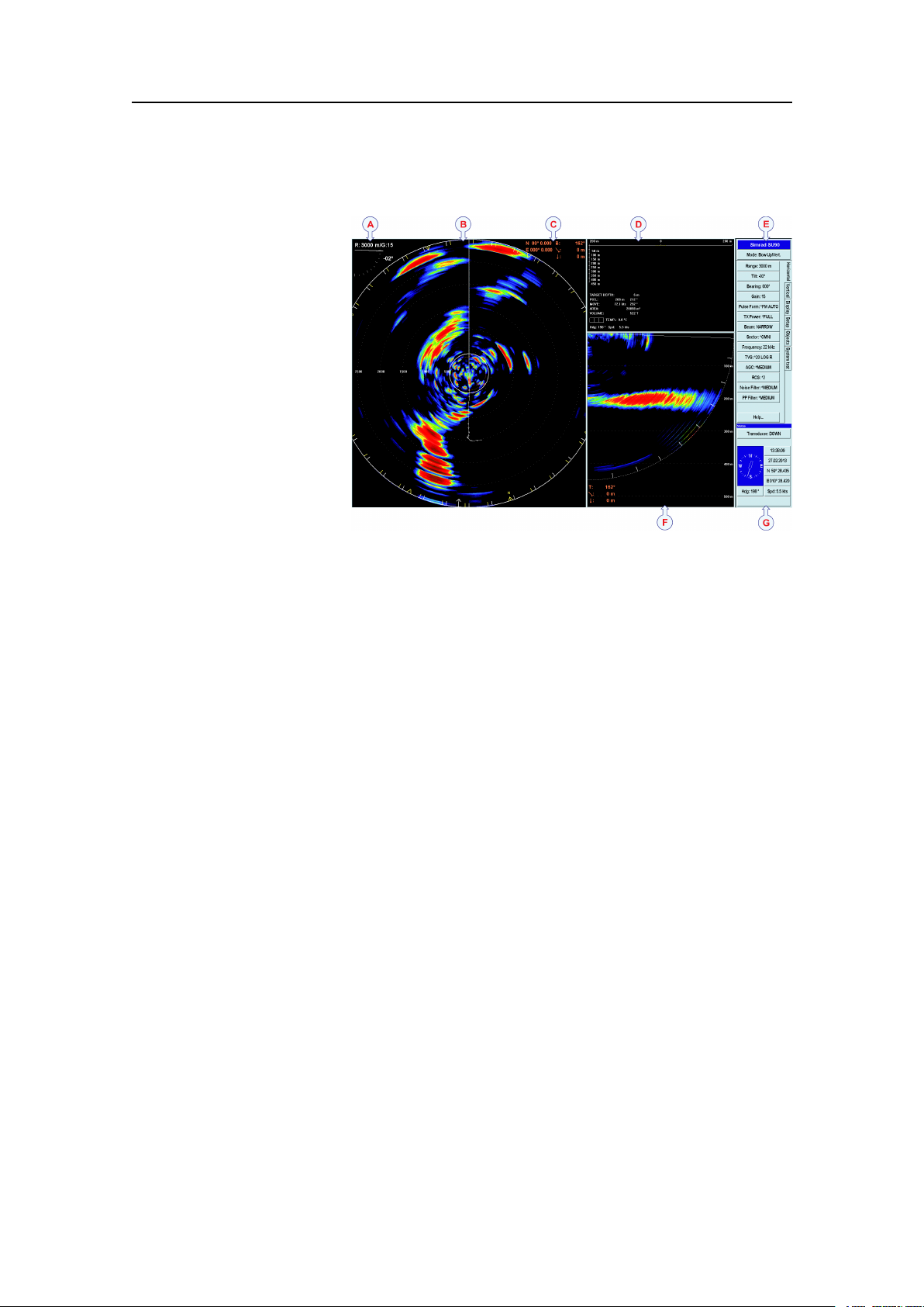
ThisSU90screencaptureshowsyouatypicalcatch
situation.Thepresentationprovidesyouwithalotof
information.
ACurrentrange,transducertiltandgain
BSonarpresentation
CCursor’sposition,bearing(relativetothevessel),
rangeanddepth
DPurseseineandtargetinformation(depthand
estimatedschoolsize),includinginformationfrom
catchmonitoringdepthsensors
EMenusystem
FVerticalview
GNavigationinformationandhullunitposition
TheSimradSU90hasbeendesignedwithnocompromises.ComparedtotheSX90,the
numberofchannelsisincreasedby50%givingthesonaranevenbetterperformance
inselectivityandrange.Thenarrowopeningangle(4,9°at30kHz)andtheincreased
sourcelevel(3dB)makestheSU90averypowerfulandhighresolutionlowfrequency
sonar.ThenarrowbeammakestheSU90evenmoreidealforsearchingshcloseto
thebottomorclosetothesurfaceatlongranges.Italsoprovidesafarbettervertical
viewwithless“bottomclimbing”thatisseenonsonarswithawiderbeam.
Greatemphasishasbeenplacedongivingthebestpossiblesonarpresentationsona
highresolutioncolourdisplay.
TheSU90ProcessorUnitiscontrolledbyMicrosoft’sWindows
whichresultinaexiblechoiceofpresentationmodesforalargerangeofuser
applications.Thesignalprocessingandbeamformingisperformedinafastdigital
16
®
operatingsystem,
381293/A

SimradSU90
signalprocessingsystemusingthefulldynamicrangeofthesignals.Inadditiontothe
traditionalsinglefrequencytransceiversystem,theSimradSU90containsanadvanced
frequencymodulatedltersystem(FM).
381293/A
17
SimradSU90
SIMRAD
PWR
MENU
SIMRAD
SIMRADSU90
(CD015050-001)
B
C
D
E
G
H
F
A
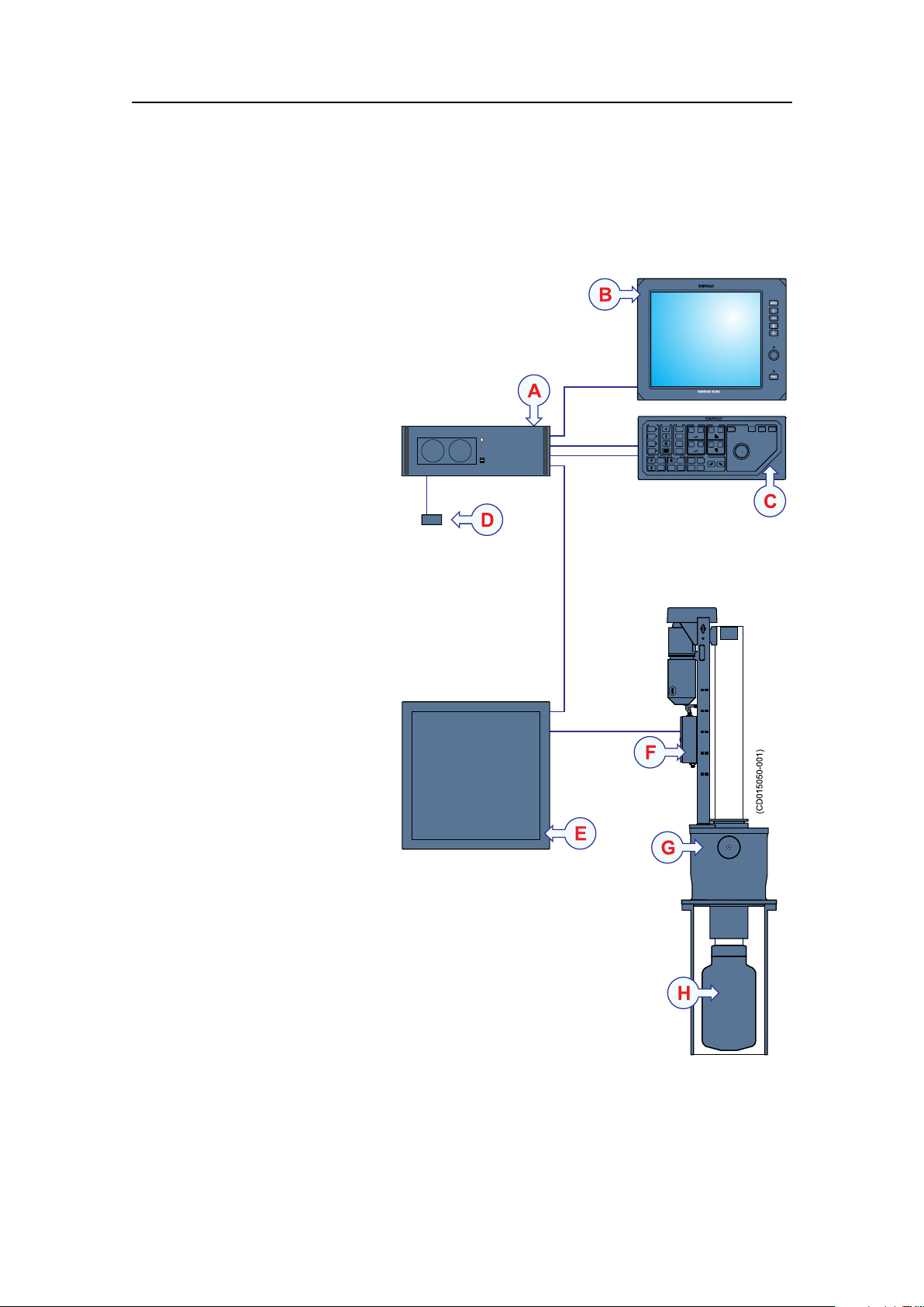
Systemdiagram
AstandardSU90systemdiagramisprovided.Interfacecapabilities,uninterruptedpower
suppliesandpowercablesarenotshown.
AProcessorUnit
BColourdisplay
COperatingPanel
DOperatingPanelPower
Supply
ETransceiverUnit
FMotorControlUnit
GHullUnit
HTransducer
Thecolourdisplayisnot
includedinthestandard
deliveryfromSimrad.Thisis
acommercialitemthatcanbe
purchasedlocally.
18
381293/A

Systemunits
TheSimradSU90comprisesthefollowingunits.
Topics
•Colourdisplayonpage19
•ProcessorUnitonpage19
•OperatingPanelonpage19
•OperatingPanelpowersupplyonpage20
•Audioamplierwithloudspeakersonpage20
•TransceiverUnitonpage20
•HullUnitonpage20
•Transduceronpage21
SimradSU90
Colourdisplay
AnycommercialcolourdisplaycanbeusedwiththeSimradSU90system.Thechosen
displaymustbedesignedformaritimeuse,anditmustmeettheminimumperformance
specications.
NotethatthecolourdisplayisnotastandardpartoftheSU90delivery.
ProcessorUnit
TheProcessorUnitisamarinecomputerbasedon
®
theMicrosoftWindows
designedforruggeduse.
Thecomputerisbasedonacommercialdesign,but
thesoftwareandhardwarehasbeenspeciedand
assembledspecicallyforSimradtosuittheSU90requirements.
ThecomputerholdsmultipleUSBportsforusewithfuturesoftwareupgrades.These
USBportswillalsoallowyoutoexportscreencapturesfromthesonar.
®
XP
operatingsystem.Itis
OperatingPanel
TheOperatingPanelcontainsallnecessarycontrol
functionsfornormaloperationoftheSU90.
Thecontrolsarearrangedinlogicalfunctiongroups,
thisgivesaclearandeasyoperation.
ThemajorityoftheSU90functionscanbeaccessed
usingthetrackballontheOperatingPanelandthemenusystemonthedisplay.You
canalsouseastandardcomputermouse.
381293/A
19

SimradSU90
OperatingPanelpowersupply
Asmallcommercialpowersupplyisimplementedtoprovidestand-bypowertothe
OperatingPanel.ThepowersupplyisconnectedtotheProcessorUnit.
Audioamplierwithloudspeakers
AnamplierwithoneortwoloudspeakersmaybeconnectedtotheProcessorUnitto
providetheaudiooutput.
Theseoptionalitemsarenotprovidedwiththestandardsonardelivery.
IfstandardcommercialPCloudspeakersareused,thesearenormallypoweredbya
separatepowersupply.
TransceiverUnit
TheSU90TransceiverUnitislocatedinthesonar
room,closetotheHullUnit.
Thetransceiverperformsthetransmissionand
receptioncontrolofthe384transmittersand384
receiverchannels.12identicaltransceiverboards
areused.TheTransceiverUnitalsoholdstwopower
supplies,anEthernetswitch,andalargecapacitorbank.
TwoEthernetcablesareusedforcommunicationwith
theProcessorUnitonthebridge,whileathirdEthernet
cableisusedtocontrolthehullunit.
Thetransducercablesfromthehullunitareplugged
intothesidewalloftheTransceiverUnitcabinetusingaspecialplug.
TheTransceiverUnitismountedonthebulkheadusingpowerfulshockabsorbers.The
connectorsforpowerandinterfacearelocatedatthebottomofthecabinet.
HullUnit
ThestandardSU92HullUnitisdesignedtolowerthetransducer1.2metersbelowthe
ship’shull.Maximumvesselspeedisthen25knots.
TheoptionalSU93HullUnitwilllowerthetransducerto1,6metersbelowthehull.With
theSU93HullUnit,themaximumvesselspeedis20knots.
Whenthesonarisswitchedon,presstheDownbuttonontheOperatingPaneltolower
thetransducerintothewater.Beforethesonarisswitchedoff,presstheUpbuttonon
theOperatingPaneltoretractthetransducerintotheinstallationtrunkforprotection.
Ifyouforgetthis,thetransducerishoistedautomaticallybeforethesonarisswitched
off.Itisalsohoistedautomaticallyifaseriousmalfunctionoccurstothecommunication
betweenthebridgeandthehullunit.
Thetransducercanalsobeloweredtoanyselectedmiddleposition.Incaseofvoltage
failure,thetransducercanberaisedorloweredmanuallybymeansofahandcrank.
20
381293/A
SimradSU90
ThesensorfortheelectronicstabilisationofthesonarbeamsishousedintheMotor
ControlUnit,whichismountedontheHullUnit.
Caution
Ifthetransducerhitslargerobjectsorbottom,thetransducershaftmaybe
bent,or-inworstcase-itcanbebrokenoff.Abrokentransducershaftwill
causewaterleakagethroughthetopoftheshaft.
Insuchcases,donotraisethetransducershafttoitsupperposition.
Topreventseriousdamage,youmusthaveawaterpumpandawarning
systeminthesonarroom.
Transducer
ThecylindricalTransducerallowsthesonarbeamtogivefull360degreescoverageof
thewatervolumefrom+10anddownto-60degrees.
Scopeofsupply
PleaseobservethestandardandoptionalpartsprovidedwiththeSimradSU90delivery.
Topics
•Mainunitsincludedwiththestandarddeliveryonpage21
•Additionalitemsonpage22
Relatedtopics
•Additionalrequireditemsonpage22
•Optionalitemsonpage25
Mainunitsincludedwiththestandarddelivery
Partnumber
SH8-203593
382924
381908
373017
Note
ThestandarddeliveryincludesanSU92hullunitwith4.6mtransducercable.Other
hullunitsandcablelengthsareoptional.
Part/unitnameanddescription
OperatingPanel
ProcessorUnit
TransceiverUnit
SU92HullUnit(with4.6mtransducercable)
Relatedtopics
•Additionalrequireditemsonpage22
•Optionalitemsonpage25
381293/A
21

SimradSU90
Additionalitems
Requireditems
SeveraladditionalitemsarerequiredfortheSU90operation.Theseitemsarenormally
notsuppliedbySimrad.Theitemsare:
•Colourdisplayonpage22
•UninterruptedPowerSupply(UPS)onpage23
•Installationtrunkonpage23
•Speedlogonpage24
•Coursegyroonpage24
Optionalitems
Severaloptionalitemsmaybeused:
•Installationtrunkonpage25
•Extendedrangeonpage26
•Scienticinterfaceonpage26
•Otherperipheralequipmentonpage26
•Audiooutputonpage28
•Externalmotionreferenceunit(MRU)onpage30
•SecondaryOperatingPanelonpage30
Additionalrequireditems
Thefollowingadditionalitemsarerequiredforafullyoperationalsystem,butthey
arenotincludedinthestandarddelivery:
Topics
•Colourdisplayonpage22
•UninterruptedPowerSupply(UPS)onpage23
•Installationtrunkonpage23
•Speedlogonpage24
•Coursegyroonpage24
Colourdisplay
TheSimradSU90requiresaVGAorDVIcolourdisplaywitharesolutionofatleast
1280x1024pixels.
TheSU90ProcessorUnitofferstwovideooutputs.Asecondarydisplaymaythen
bemountedatanotherlocationonthevessel.Thetwodisplaywillalwaysshowthe
presentation.
same
22
381293/A

SimradSU90
IfyoualsowishtocontroltheSU90fromthissecondarydisplaylocation,youcanadd
anextraOperatingPanel.
Relatedtopics
•SecondaryOperatingPanelonpage30
UninterruptedPowerSupply(UPS)
InordertoensurecontinuousoperationoftheSimradSU90independentofvarying
qualityofthevessel'smainssupply,theuseofuninterruptedpowersupplies(UPS)is
required.
Twouninterruptedpowersupplyunitsareused:
•Oneisusedtopowerthebridgeunits.
•OneisusedtopowertheTransceiverUnit.
Important
Uninterruptedpowersupply(UPS)unitsarenotincludedinthestandardSU90delivery.
Severalcommercialtypesareavailable.TochoosethebestUPSfortheSU90
installation,considerenvironmentalconditions,spaceavailable,theavailabilityand
durationofthebatteries,andthepowerrequirementsoftheSU90units.
TheminimumspecicationsfortheUninterruptedPowerSupply(UPS)are:
•Inputvoltage:Musttvesselsupplyvoltage
•Outputvoltage:230Vac,50Hz
•Outputpower:
–Bridgeunits:1000W
–Sonarroomunits:1500W
•Outputrequirement:TheACoutputvoltagemustbeasinewave
Relatedtopics
•Powerspecicationsonpage223
Installationtrunk
Theinstallationtrunkrequiredforthehullunitinstallationisnotincludedinthestandard
delivery.
Theinstallationtrunkmaybefabricatedbytheshipyard,orsuppliedbySimradasan
option.Themechanicaldrawingsofthetrunkandblindcoverareincludedinthis
manual.TheSimradSU90sonarisdeliveredwithoutadomesystem.
TheoptionaltrunkofferedbyKongsbergMaritimeisapprovedbyDetNorskeV eritas
(DNV),andincludesablindcoverandagasket.
Relatedtopics
•Installationtrunkonpage25
381293/A
23

SimradSU90
Speedlog
Inordertooperatecorrectly,theSimradSU90requiresinputfromaspeedlog.Inmost
casesasuitablesensorisalreadyinstalledonthevessel.Adifferentialglobalpositioning
system((D)GPS)canalsobeused.
Speedloginterfaceparameters:
•Serialline:StandardNMEA0183telegramformat
Relatedtopics
•Connectingthespeedlogonpage142
•Conguringandtestingtheinterfacetothespeedlogonpage157
Coursegyro
Inordertooperatecorrectly,theSimradSU90requiresinputfromacoursegyro.Inmost
casesasuitablesensorisalreadyinstalledonthevessel.
Coursegyrointerfaceparameters:
•Serialline:StandardNMEA0183telegramformat
Ifthecoursegyroinstalleddoesnotoutputthecorrectserialinterfaceformat,anoptional
gyrointerfaceboxisavailable.Itwillconvertthefollowingsynchroandstepping
gyrosignals:
•3-phasesynchrosignal,20to150VL-L,50/60/400Hz,gearration1:360or1:180
•3-phasesteppersignal,20to150VL-L,gearration1:360or1:180
Orderinginformation
LR40Gyrointerface
298-078535
Relatedtopics
•Connectingthecoursegyroonpage143
•Conguringandtestingtheinterfacetothecoursegyroonpage158
24
381293/A

Optionalitems
Thefollowingoptionalequipmentandfunctionalitymaybeorderedatanadditional
chargetoaugmentthestandardSimradSU90systemdelivery,orpurchasedlocally
bytheinstallationshipyardorenduser.
Topics
•Installationtrunkonpage25
•Extendedrangeonpage26
•Scienticinterfaceonpage26
•Otherperipheralequipmentonpage26
•Audiooutputonpage28
•Externalmotionreferenceunit(MRU)onpage30
•SecondaryOperatingPanelonpage30
SimradSU90
Hullunit
ThestandardSU92HullUnitcanbelowered1.2metersataspeedof21knots.The
mountingangehas24boltswithpitchcentrediameter(PCD)680mm.Otherhull
unitsareavailableaslistedbelow.
HullunitsavailablefromKongsbergMaritime
HullUnitSpecicationsOrderno.
SU92*1.2m,21knots,24bolts,PCD680mm,4.6mtransducercable
SU92
SU93
SU93
(*=SU92with4.6mtransducercableisthestandardhullunit)
1.2m,21knots,24bolts,PCD680mm,7mtransducercable
1.6m,16knots,20bolts,PCD620mm,4.6mtransducercable
1.6m,16knots,20bolts,PCD620mm,7mtransducercable
373017
386420
373018
386422
Installationtrunk
Theinstallationtrunkmaybefabricatedbytheinstallationshipyard,orsuppliedby
KongsbergMaritime.Thesameinstallationintrunkisusedforallhullunits.
IfyouarereplacinganSX90orSP90sonarwithanewSU90,youcanuseyourexisting
trunk.However,duetothelargertransducerontheSU90sonar,atrunkextensionmust
beused.
OptionalinstallationtrunksavailablefromKongsbergMaritime
Trunktype
SU92/SU9324bolts,PCD680mm
Extension24bolts,PCD680mm
SpecicationsOrderno.
Relatedtopics
•Mountingthetrunkextensiononpage58
381293/A
376655
374676
25

SimradSU90
•SU92Hullunitdimensionsdrawingonpage263
•SU93Hullunitdimensionsdrawingonpage265
•SU92/SU93Mountingtrunkproductiondrawingonpage267
•SU92/SU93Extensiontrunkproductiondrawingonpage269
•SU92/SU93Blindcoverdrawingonpage271
Extendedrange
Duetointernationalregulations,sonarswithoperationalrangeexceeding5000meters
canonlybeexportedonlicense.
ForthisreasonthestandardrangeontheSU90hasbeenlimitedto4500meters.
However,ifanexportlicenceisobtained,themaximumrangecanbeextendedto
8000meters.
Orderinginformation
Extended8000mrange
314506
Scienticinterface
TheScienticOutputisdesignedforresearchpurposes.Whenactivated,thefollowing
dataareavailableonanEthernet(LAN)output:
•Beamdata
•Targetdata
•Ownshipdata
•Geardata
ThescienticoutputoptionmayalsoincludesoftwareforaScienticDataLogger.
Orderinginformation
Scienticinterface
KIT-203477
Otherperipheralequipment
TheSimradSU90providesseveralseriallines.Twooftheseareusedtointerfacetothe
speedlogandcoursegyro.Theremainingseriallinescanbeusedtocommunicate
withotherperipheralequipment.
26
381293/A

Thisequipmentmayforexampleinclude:
•DifferentialGlobalPositioningSystem((D)GPS)
•Motionreferenceunit(MRU)
•Echosounder
•Catchmonitoringsystem
•Trawlsonar
•Currentmetersystem
•Radiobuoysystem
Alltheseperipheralsmaybeconnectedusingtheseriallines.Mostofthemwill
communicatebymeansofthestandardNMEA0183format.
Notethatperipheralequipmentandsensorsmustbepurchasedlocallybytheinstallation
shipyardorenduser.
SimradSU90
DifferentialGlobalPositioningSystem((D)GPS)
A(D)GPSmaybeinterfacedwiththeSimradSU90sonartoestablishthevessel’s
positionandprovidecursorandmarkerlatitudeandlongitude.
Inadditiontonavigationaldata,the(D)GPSmayalsobeusedfortheinputofspeedlog
information.Most(D)GPSareequippedtopresentcourseinformation,butthisdatais
generallytooinconsistenttoprovideastablesonarpresentation.
Relatedtopics
•Positioningsysteminterfaceonpage286
Motionreferenceunit(MRU)
TheSU90offersabuilt-inmotionsensortoprovidestabilisationofthesonarbeams.
Youmayincreasetheefciencyandaccuracyifyouinstallaseparatemotionreference
unit(MRU).TheSU90providesaninterfacetotheMRU3sensormanufacturedby
KongsbergMaritime.Relevantinstallationproceduresareincludedinthismanual.
Relatedtopics
•Externalmotionreferenceunit(MRU)onpage30
•Connectinganexternalmotionreferenceunit(MRU)onpage144
Catchmonitoringsystem
Toprovidetrawlandpurseseinedepthinformationonthesonar’sdisplay,thefollowing
Simradcatchmonitoringsystemsmaybeconnected:
•SimradPISeriesCatchmonitoringsystems
•SimradITIIntegratedTrawlInstrumentationsystem
Relatedtopics
•Catchmonitoringsysteminterfaceonpage287
381293/A
27

SimradSU90
Trawlsonar
Toprovidetrawlinformationonthesonar’sdisplay,oneofthefollowingSimradtrawl
systemsmaybeconnected:
•SimradFS903Trawlsonar
•SimradFS3300Trawlsonar
•SimradFS20/25Trawlsonar
•SimradFS70Trawlsonar
Relatedtopics
•Trawlsonarinterfaceonpage286
Currentmetersystem
Acurrentmetersystemmaybeconnectedtothesonartodisplaythedirectionandspeed
oftheseacurrentsonvariousdepths.Thefollowingcurrentsystemcanbeconnected:
•KaijoDCG-200
Relatedtopics
•Currentmeterinterfaceonpage287
Radiobuoysystem
AGPSbasedradiobuoysystemmaybeconnectedtothesonartoshowthepositionand
buoydataonthedisplay.Thefollowingbuoysystemscanbeconnected:
•SERPE
•Ariane
•Ryokusei
Relatedtopics
•Radiobuoysconnectioninterfaceonpage287
Audiooutput
Topics
•Abouttheaudiooutputonpage29
•PoweredspeakersystemforPCuseonpage29
•Stereosystemwithamplierandtwoormoreloudspeakersonpage29
Relatedtopics
•Mini-jacktophonoaudiocableonpage294
•Commercialpoweredspeakersystemonpage304
28
381293/A
Loading...