


 Loading...
INSTRUCTION MANUAL
Simrad AP50
Autopilot

Note!
Simrad AS makes every effort to ensure that the information contained within this document is correct. However, our equipment is continuously being improved and updated, so we cannot assume liability for any errors which may occur.
Warning!
The equipment to which this manual applies must only be used for the purpose for which it was designed. Improper use or maintenance may cause damage to the equipment or injury to personnel. The user must be familiar with the contents of the appropriate manuals before attempting to operate or work on the equipment.
Simrad AS disclaims any responsibility for damage or injury caused by improper installation, use or maintenance of the equipment.
Copyright
© 2003 Simrad AS
The information contained within this document remains the sole property of Simrad AS.
No part of this document may be copied or reproduced in any form or by any means, and the information contained within is not to be communicated to a third party, without the prior written consent of Simrad AS.

General Information
Instruction Manual
This manual is intended as a reference guide for the correct installation and operation of the Simrad AP50 autopilot.
Great care has been taken to simplify the set-up and operation of the AP50; however, an autopilot is a complex electronic system. It is affected by sea conditions, speed of the vessel, and vessel hull shape and size.
Please take the time to read this manual to gain a thorough understanding of the Simrad AP50 autopilot’s system components and operation, as well as their relationship to a complete AP50 autopilot system.
Other documentation included in this manual is a warranty card. This card must be completed by the authorized dealer that performed the installation and mailed-in to activate the warranty.
Caution ! An autopilot is a very useful navigational aid, but it DOES NOT under any circumstance replace a human navigator.
Do not use automatic steering when:
•In heavy traffic areas or in narrow waters
•In poor visibility or extreme sea conditions
•When in areas where use of autopilot is prohibited by law When using an autopilot:
•Do not leave the helm unattended
•Do not place any magnetic material or equipment near any magnetic or fluxgate compass used in the autopilot system
•Verify the course and position of the vessel at regular intervals
•Always switch to Standby mode and reduce speed in sufficient time to avoid hazardous situations
20221032B |
1 |

Simrad AP50 Autopilot
Document revisions
Rev |
Date |
Written by |
Checked by |
Approved by |
||||||
A |
03.06.02 |
|
NG |
|
GK |
|
GHR |
|||
B |
18.06.03 |
|
|
|
|
|
|
|
|
|
|
|
|
|
|
|
|
|
|
||
|
|
|
|
|
|
|
|
|
||
|
|
|
|
|
|
|
|
|
|
|
|
|
|
|
|
|
|
|
|
|
|
|
|
|
|
|
|
|
|
|
|
|
|
|
|
|
|
|
|
|
|
|
|
Document history
Rev. A Original Issue
Rev. B Updated according to software revision V1R2. Minor corrections in text. RF14XU added.
2 |
20221032B |
|
|
General Information |
|
|
|
Contents |
|
1 |
GENERAL INFORMATION ............................................................................. |
11 |
|
|
1.1 |
Introduction .................................................................................................. |
11 |
|
1.2 |
How to Use This Manual.............................................................................. |
12 |
|
1.3 |
System Components ..................................................................................... |
13 |
|
1.4 |
AP50 Control Unit........................................................................................ |
14 |
|
1.5 |
Junction Units ............................................................................................... |
14 |
|
1.6 |
Rudder Feedback Units ................................................................................ |
14 |
|
|
RF300S Rudder Feedback Unit.................................................................... |
14 |
|
|
RF45X Rudder Feedback Unit ..................................................................... |
15 |
|
|
RF14XU Rudder Feedback Unit .................................................................. |
15 |
|
1.7 |
Heading Sensors ........................................................................................... |
15 |
|
|
RC25/RFC35R Rate Compass...................................................................... |
15 |
|
|
CD100A Course Detector and CDI35 Course Detector Interface................ |
15 |
|
|
General NMEA Compasses.......................................................................... |
15 |
|
|
HS50 GPS Heading Sensor .......................................................................... |
15 |
|
|
Other Compass Models ................................................................................ |
16 |
|
|
CI300X Compass Interface...................................................................... |
16 |
|
|
GI50 Gyro Interface................................................................................. |
16 |
|
1.8 |
Optional Equipment...................................................................................... |
16 |
|
|
AP51 Remote Control .................................................................................. |
16 |
|
|
R3000X Remote Control .............................................................................. |
16 |
|
|
S100 NFU Steering Lever ............................................................................ |
17 |
|
|
S35 NFU Steering Lever .............................................................................. |
17 |
|
|
FU50 Follow-Up Steering Lever.................................................................. |
17 |
|
|
F1/2 NFU Remote ........................................................................................ |
17 |
|
|
TI50 Thruster Interface................................................................................. |
17 |
|
|
AD50 Analog Drive...................................................................................... |
18 |
|
|
RI35 Mk2 Rudder Angle Indicator............................................................... |
18 |
|
|
NI300X NMEA Interface Unit ..................................................................... |
18 |
2 |
OPERATION OF THE AUTOPILOT .............................................................. |
19 |
|
|
2.1 |
Overview ...................................................................................................... |
19 |
|
2.2 |
ON/OFF - Standby Mode (STBY) ............................................................... |
22 |
|
2.3 |
AP50 with MSD50 Stern Drive unit............................................................. |
24 |
|
|
Zero point setting.......................................................................................... |
24 |
|
|
Operation ...................................................................................................... |
24 |
|
2.4 |
Follow-Up (FU) Steering.............................................................................. |
25 |
|
2.5 |
Non-Follow-Up (NFU) Steering .................................................................. |
25 |
|
|
S100 (NFU) Steering Lever.......................................................................... |
25 |
20221032B |
3 |

Simrad AP50 Autopilot
|
|
F1/2 (NFU) Push Button Remote Control.................................................... |
25 |
|
|
R3000X Remote Control (NFU) .................................................................. |
26 |
|
|
S35 NFU Steering Lever .............................................................................. |
26 |
|
2.6 |
Automatic Steering ....................................................................................... |
27 |
|
|
AUTO Mode................................................................................................. |
27 |
|
|
AUTO-WORK Mode ................................................................................... |
28 |
|
2.7 |
Thruster Steering .......................................................................................... |
29 |
|
2.8 |
Navigating with the AP50 ............................................................................ |
30 |
|
|
Route Navigation.......................................................................................... |
31 |
|
|
Electronic Chart System (ECS) .................................................................... |
32 |
|
|
Selecting a Different Navigator.................................................................... |
33 |
|
|
NAV-WORK Mode...................................................................................... |
33 |
|
2.9 |
Dodging ........................................................................................................ |
34 |
|
|
Dodging in AUTO Mode.............................................................................. |
34 |
|
|
Dodging in NAV Mode ................................................................................ |
35 |
|
2.10 |
TURN Mode ................................................................................................. |
36 |
|
|
U-turn............................................................................................................ |
36 |
|
|
C-turn............................................................................................................ |
36 |
|
2.11 |
Multiple Station System ............................................................................... |
37 |
|
2.12 |
Lock Function............................................................................................... |
37 |
|
|
Standard Operation ....................................................................................... |
37 |
|
|
Master Operation .......................................................................................... |
38 |
|
2.13 |
External system selection ............................................................................. |
39 |
|
2.14 |
User Set-up Menu......................................................................................... |
39 |
|
|
Alternating Course Knob Icon...................................................................... |
39 |
|
|
STANDBY Mode ......................................................................................... |
39 |
|
|
AUTO Mode................................................................................................. |
41 |
|
|
AUTO-WORK Mode ................................................................................... |
43 |
|
|
NAV Mode ................................................................................................... |
44 |
|
|
NAV-WORK Mode...................................................................................... |
45 |
|
2.15 |
Instrument Screens and Menu ...................................................................... |
46 |
|
|
Screen Selection ........................................................................................... |
48 |
|
|
Instrument Set-up. ........................................................................................ |
48 |
3 |
TECHNICAL SPECIFICATIONS .................................................................... |
49 |
|
|
3.1 |
AP50 Autopilot System ................................................................................ |
49 |
|
3.2 |
AP50 Control Unit........................................................................................ |
50 |
|
3.3 |
AP51 Remote Control .................................................................................. |
51 |
|
3.4 |
Junction Units ............................................................................................... |
52 |
|
3.5 |
RC25/RFC35R Rate Compass...................................................................... |
53 |
|
3.6 |
CDI35 Course Detector Interface ................................................................. |
54 |
4 |
20221032B |
|
|
|
General Information |
|
3.7 |
CD100A Course Detector............................................................................. |
55 |
|
3.8 |
CD109 Course Detector................................................................................ |
55 |
|
3.9 |
RI35 Mk2 Rudder Angle Indicator............................................................... |
56 |
|
3.10 |
RF300S Rudder Feedback Unit.................................................................... |
57 |
|
3.11 |
RF45X Rudder Feedback Unit ..................................................................... |
58 |
|
3.12 |
RF14XU Rudder Feedback Unit .................................................................. |
59 |
|
3.13 |
GI50 Gyro Interface...................................................................................... |
60 |
|
3.14 |
CI300X Compass Interface .......................................................................... |
61 |
|
3.15 |
NI300X NMEA Interface ............................................................................. |
62 |
|
3.16 |
TI50 Thruster Interface................................................................................. |
63 |
|
3.17 |
AD50 Analog Drive...................................................................................... |
63 |
|
3.18 |
R3000X Remote Control .............................................................................. |
64 |
|
3.19 |
S100 NFU Steering Lever ............................................................................ |
65 |
|
3.20 |
S35 NFU Steering Lever .............................................................................. |
65 |
|
3.21 |
F1/2 Remote Control .................................................................................... |
66 |
|
3.22 |
FU50 Steering Lever .................................................................................... |
67 |
|
3.23 |
Environmental Protection ............................................................................. |
68 |
|
3.24 |
NMEA Sentences ......................................................................................... |
68 |
4 |
INSTALLATION ................................................................................................. |
71 |
|
|
4.1 |
General.......................................................................................................... |
71 |
|
4.2 |
Unpacking and Handling .............................................................................. |
71 |
|
4.3 |
Installation Index .......................................................................................... |
71 |
|
4.4 |
Determining System Configuration.............................................................. |
73 |
|
4.5 |
AP50 System Layout .................................................................................... |
73 |
|
4.6 |
RF300S Rudder Feedback Unit.................................................................... |
74 |
|
4.7 |
RF45X Rudder Feedback Unit ..................................................................... |
76 |
|
|
Electrical Connection ................................................................................... |
77 |
|
|
Mechanical Alignment ................................................................................. |
79 |
|
4.8 |
RF14XU Rudder Feedback Unit .................................................................. |
80 |
|
|
Mechanical mounting ................................................................................... |
80 |
|
|
Electrical installation .................................................................................... |
80 |
|
|
Final check.................................................................................................... |
84 |
|
4.9 |
J50 Junction Unit .......................................................................................... |
85 |
|
|
Cable Connections........................................................................................ |
85 |
|
|
Grounding and Radio Frequency Interface (RFI)......................................... |
86 |
|
|
Junction Unit Terminals ............................................................................... |
86 |
|
|
System Select................................................................................................ |
87 |
|
|
AUTO/STANDBY Toggling ....................................................................... |
87 |
|
|
External Alarm (Non Wheelmark System)................................................... |
88 |
|
|
External Alarm (Wheelmark System) .......................................................... |
88 |
20221032B |
5 |

Simrad AP50 Autopilot
|
4.10 |
Drive Unit Installation .................................................................................. |
89 |
|
|
Connecting a Reversible Pump..................................................................... |
91 |
|
|
Connecting a Hydraulic Linear Drive........................................................... |
92 |
|
|
Solenoids (externally powered, common positive).................................. |
92 |
|
|
Solenoids (externally powered, common negative)................................. |
93 |
|
|
Connecting Solenoid Valves ........................................................................ |
92 |
|
|
Solenoids (not externally powered) ......................................................... |
93 |
|
4.11 |
Control Unit.................................................................................................. |
94 |
|
|
Panel-mounting............................................................................................. |
94 |
|
|
Optional Bracket mounting .......................................................................... |
94 |
|
|
RobNet Network Cables............................................................................... |
95 |
|
|
AP51 Remote Control Connection ............................................................... |
98 |
|
|
AP51 in a Wheelmark System ................................................................. |
98 |
|
|
JP21 Jack Point Installation.......................................................................... |
98 |
|
4.12 |
RC25/RFC35R Rate Compass...................................................................... |
99 |
|
|
RFC35 Fluxgate Compass .......................................................................... |
102 |
|
4.13 |
FU50 Steering Lever .................................................................................. |
102 |
|
4.14 |
TI50 Thruster Interface............................................................................... |
102 |
|
4.15 |
AD50 Analog Drive.................................................................................... |
102 |
|
4.16 |
R3000X Remote Control ............................................................................ |
103 |
|
4.17 |
S100 NFU Lever Installation...................................................................... |
103 |
|
4.18 |
S35 NFU Steering Lever ............................................................................ |
104 |
|
4.19 |
F1/2 Remote Control .................................................................................. |
104 |
|
4.20 |
Interfacing to Optional Equipment (THD, Navigation Receiver, etc.)....... |
105 |
|
|
Single NMEA input/output......................................................................... |
105 |
|
|
Double NMEA input/output ....................................................................... |
106 |
|
|
NMEA Compass In .................................................................................... |
106 |
|
|
Radar Clock/Data ....................................................................................... |
107 |
|
|
Analog Heading Repeater........................................................................... |
107 |
|
|
Digital Heading Repeater ........................................................................... |
108 |
|
|
GI50 Gyro Interface.................................................................................... |
109 |
|
|
NI300X NMEA Interface Unit ................................................................... |
111 |
|
|
CI300X Compass Interface Unit ................................................................ |
112 |
|
|
CD100A Course Detector........................................................................... |
114 |
|
|
CDI35 Interface .......................................................................................... |
115 |
5 |
SOFTWARE SET-UP PROCEDURE ............................................................. |
117 |
|
|
5.1 |
Description of Installation Set-up............................................................... |
117 |
|
5.2 |
Installation Menu........................................................................................ |
118 |
|
|
Language selection ..................................................................................... |
119 |
|
|
Dockside ..................................................................................................... |
119 |
6 |
20221032B |
|
|
General Information |
|
|
|
Master Operation ................................................................................... |
121 |
|
|
Boat Type............................................................................................... |
121 |
|
|
Boat Length............................................................................................ |
121 |
|
|
Drive Unit Voltage................................................................................. |
121 |
|
|
Rudder Feedback Calibration ................................................................ |
122 |
|
|
Rudder Calibration................................................................................. |
123 |
|
|
Rudder Test............................................................................................ |
124 |
|
|
Set Rudder Zero ..................................................................................... |
125 |
|
|
Rudder Limit.......................................................................................... |
125 |
|
|
Rudder Deadband................................................................................... |
125 |
|
|
Thruster.................................................................................................. |
126 |
|
|
Interface Set-up........................................................................................... |
126 |
|
|
Sea Trial...................................................................................................... |
132 |
|
|
Compass Calibration.............................................................................. |
133 |
|
|
Compass Offset...................................................................................... |
134 |
|
|
Set Thrust Direction, On/Off Thruster................................................... |
135 |
|
|
Thruster Calibration, Analog Thruster................................................... |
135 |
|
|
Thruster zero .......................................................................................... |
135 |
|
|
Direction and Maximum Thrust STBD, Analog Thruster ..................... |
136 |
|
|
Direction and Maximum Thrust PORT, Analog Thruster ..................... |
136 |
|
|
Minimum Thrust, Analog Thruster........................................................ |
137 |
|
|
Speed source .......................................................................................... |
137 |
|
|
Set Cruising Speed................................................................................. |
138 |
|
|
Set Rudder Zero ..................................................................................... |
138 |
|
|
Set Rate of Turn..................................................................................... |
138 |
|
|
Adjust rudder angle/Set rate of turn....................................................... |
139 |
|
|
Manual Tuning....................................................................................... |
140 |
|
|
Automatic tuning ................................................................................... |
141 |
|
|
Speed Response ..................................................................................... |
143 |
|
5.3 |
Final Test .................................................................................................... |
143 |
|
5.4 |
Providing User Training ............................................................................. |
144 |
6 |
ADVANCED SETTINGS.................................................................................. |
145 |
|
|
6.1 |
Service Menu.............................................................................................. |
145 |
|
|
System Data................................................................................................ |
145 |
|
|
NMEA Data................................................................................................ |
146 |
|
|
NMEA Port Test (J50 hardware)................................................................ |
147 |
|
|
Master Reset ............................................................................................... |
147 |
|
6.2 |
Settings Menu ............................................................................................. |
148 |
|
|
Steering....................................................................................................... |
148 |
|
|
W Init rudder.......................................................................................... |
148 |
20221032B |
7 |

Simrad AP50 Autopilot
|
W Autotrim ............................................................................................ |
148 |
|
Autotrim................................................................................................. |
148 |
|
Course Adjust......................................................................................... |
149 |
|
Compass difference................................................................................ |
149 |
|
Off Heading lim ..................................................................................... |
149 |
|
Drive engage .......................................................................................... |
150 |
|
Drive type............................................................................................... |
151 |
|
Drive out ................................................................................................ |
151 |
|
Prop. gain ............................................................................................... |
151 |
|
Seastate .................................................................................................. |
151 |
|
Rudder.................................................................................................... |
151 |
|
Counter rudder ....................................................................................... |
152 |
|
W Seastate .................................................................................................. |
152 |
|
W Rudder.................................................................................................... |
152 |
|
W Count rudder .......................................................................................... |
152 |
|
W Rudder limit ...................................................................................... |
152 |
|
Cruising speed........................................................................................ |
152 |
|
Speed response....................................................................................... |
152 |
|
Transition Speed .................................................................................... |
153 |
|
Nav Gain ................................................................................................ |
153 |
|
Minimum rudder .................................................................................... |
153 |
|
Turn mode.............................................................................................. |
154 |
|
Rate of Turn ........................................................................................... |
154 |
|
W Rate of Turn ...................................................................................... |
154 |
|
Radius .................................................................................................... |
154 |
|
W Radius................................................................................................ |
154 |
|
Added stop time ..................................................................................... |
154 |
|
Init NAV ................................................................................................ |
155 |
|
Turn Gain............................................................................................... |
155 |
|
W Turn Gain .......................................................................................... |
155 |
|
Rate Sensitivity ...................................................................................... |
155 |
|
Thruster....................................................................................................... |
156 |
|
Thruster inhibit....................................................................................... |
156 |
|
Thruster sensitivity................................................................................. |
156 |
|
Thruster gain .......................................................................................... |
156 |
|
Minimum thrust ..................................................................................... |
157 |
|
Thruster hyst .......................................................................................... |
158 |
|
Thruster Drive........................................................................................ |
158 |
|
Response delay....................................................................................... |
158 |
7 |
MAINTENANCE ............................................................................................... |
161 |
8 |
20221032B |
|
|
|
General Information |
|
7.1 |
Control unit................................................................................................. |
161 |
|
7.2 |
Junction Unit............................................................................................... |
161 |
|
7.3 |
Rudder Feedback ........................................................................................ |
161 |
|
7.4 |
Compass (RC25/RFC35R) ......................................................................... |
161 |
|
7.5 |
Drive unit.................................................................................................... |
161 |
|
7.6 |
Exchange of software program................................................................... |
162 |
8 |
TROUBLESHOOTING .................................................................................... |
165 |
|
|
8.1 |
Warnings..................................................................................................... |
165 |
9 |
SPARE PARTS LIST ........................................................................................ |
171 |
|
10 |
GLOSSARY........................................................................................................ |
177 |
|
11 |
INDEX................................................................................................................. |
181 |
|
20221032B |
9 |

Simrad AP50 Autopilot
This page is intentionally left blank
10 |
20221032B |

General Information
1 GENERAL INFORMATION
1.1 Introduction
Congratulations on the purchase of your new Simrad AP50 autopilot system and thank you for selecting what we feel is one of the most advanced autopilot systems available on the market today.
Today, Simrad manufactures a complete range of autopilots for all types of vessels, from leisure boats to advanced steering systems for merchant marine vessels. Our factory for these products Simrad Egersund AS, is located in Egersund on the southwest coast of Norway. The company's involvement in autopilots began in 1953 with equipment for the North Sea fishing fleet under the brand name Robertson. Professional mariners around the world acknowledge that the Robertson and Simrad brand names are synonymous with the absolute best in autopilot technology.
The AP50 autopilot from Simrad represents yet another step forward in autopilot technology with the intent of providing small fishing boats and work boats up to 200 feet with a host of new features. The system can be expanded and enhanced with a selection of options and accessories.
The brain in the AP50 autopilot system is the single "intelligent" junction unit that communicates with all other system modules on a RobNet network. The RobNet has been developed to establish a reliable digital communication and power distribution network between the units in the system. The RobNet simplifies installation and enables the AP50 system to be easily expanded at any time. Any unit that is connected to the autopilot system via RobNet is called a RobNet Unit (See Junction Unit Comparison table on page 14).
The AP50 system is produced and tested in accordance with the European Marine Equipment Directive 96/98. This means that the AP50 complies with the highest level of tests for nonmilitary marine electronic navigation equipment existing today.
The Marine Equipment Directive 96/98/EC (MED), as amended by 98/95/EC for ships flying EU or EFTA flags, applies to all new ships, to existing ships not previously carrying such equipment, and to ships having their equipment replaced.
This means that all system components covered by annex A1 must be type-approved accordingly and must carry the Wheelmark, which is a symbol of conformity with the Marine Equipment Directive.
20221032B |
11 |

Simrad AP50 Autopilot
While the AP50 may be installed on vessels not needing to comply with the Marine Equipment Directive, those requiring compliance must have one AP50 Control Unit set-up as a “master unit” in order for the installation to be approved. Simrad has no responsibility for the incorrect installation or use of the AP50 autopilot, so it is essential for the person in charge of the installation to be familiar with the relevant requirements as well as with the contents of this manual, which covers correct installation and use.
The purpose of the Marine Equipment Directive is to enhance safety at sea and to prevent marine pollution through the uniform application of the relevant international instruments relating to equipment listed in Annex A1.
As there are many interfacing requirements in the standards/codes, integrated systems and integrated certification lead to more efficient and effective management of safety, environmental, issues and quality.
The Marine Equipment Directive also constitutes a part of the International Safety Management (ISM) Code. The ISM Code was included as a new chapter (IX) of SOLAS in 1994, and is mandatory for: passenger ships not later than 1st of July, 1998; oil tankers; chemical tankers; gas carriers; bulk carriers and cargo high speed craft of 500 gross tonnage and upwards not later than 1st of July, 1998; and other cargo ships and mobile offshore drilling units of 500 gross tonnage and upwards not later than 1st of July, 2002.
It is required that both the shipping company and ships shall be certified by the Administration (the government of the state whose flag the ship is entitled to fly), by an organization recognized by the Administration or by the government of the country acting on behalf of the Administration.
1.2 How to Use This Manual
This manual is intended as a reference guide for installing, operating and maintaining the Simrad AP50 autopilot. Great care has been taken to simplify the set-up and operation and of the AP50; however, an autopilot is a complex electronic system. It is affected by sea conditions, speed of the vessel, and vessel hull shape and size.
Please take the time to read this manual to get a thorough understanding of the Simrad AP50 autopilot’s system components and operation, as well as their relationship to a complete AP50 autopilot system.
12 |
20221032B |
|
General Information |
|
At the end of this manual, you will find an index and a glossary, |
|
which will help you when studying the manual. |
|
Other documentation provided with your system includes a |
|
warranty card. |
Note ! |
The Warranty Card must be completed by the authorized dealer |
|
that performed the installation and mailed-in to activate the |
|
warranty. |
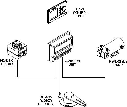
1.3 System Components
A basic AP50 system may consist of the following units (refer to Figure 1-1):
•AP50 Control Unit with accessories
•Heading Sensor
•Rudder Feedback Unit with transmission link
•Junction Unit
•Drive Unit
The basic system can be expanded with remote control unit, hand held remote and steering lever.
Figure 1-1 AP50 Basic system
20221032B |
13 |

Simrad AP50 Autopilot
1.4 AP50 Control Unit
This compact autopilot control for panel, bulkheador bracketmounting has a rotary course knob and a large LCD for readout of autopilot data. It also has two RobNet connectors for system interconnection and expansion.
1.5 Junction Units
The junction unit in the AP50 autopilot system contains the steering computer, interface circuits to all system components, and drive circuits for the drive unit motor and clutch. Two models, J50 and J50-40, are available.
|
J50 |
J50-40 |
Supply voltage |
10-40 V |
10-40 V |
Motor current (continuous/peak) |
10/20A |
20/40A |
Number of RobNet units* (+J50) |
15 |
15 |
NMEA ports (input/output) |
2 |
2 |
Solenoid output |
Yes |
Yes |
Galvanic insulated solenoids |
Yes |
No |
Input for NFU control |
Yes |
Yes |
External alarm |
Yes |
Yes |
Radar clock/data interface |
Yes |
Yes |
* AP50 Control Unit, AP51 Remote Control, RFC35R Rate Compass, FU50 Follow-up lever, CI300X Compass Interface, NI300X NMEA Interface, TI50 Thruster Interface, AD50 Analog Drive.
Table 1-1 Junction Unit Model Comparison
1.6 Rudder Feedback Units
RF300S Rudder Feedback Unit
This rudder feedback unit with transmission link and 10 m (30 feet) of cable transforms the angular travel of the rudder to a digital signal read by the autopilot steering computer. It is to be used on small to medium size vessels.
14 |
20221032B |

General Information
RF45X Rudder Feedback Unit
This rudder feedback unit with T45 transmission link and 2 m (6 feet) of cable transforms the angular travel of the rudder to a digital signal read by the autopilot steering computer. It is to be used on medium to large size vessels.
RF14XU Rudder Feedback Unit
This unit can replace the RF45X Rudder Feedback Unit in installations where a more rugged construction of the feedback unit is preferred. Besides electronic circuitry to generate feedback signals for the autopilot and rudder angle indicators it has been provided with 2 sets of limit switches.
1.7 Heading Sensors
The AP50 autopilot system can be used with the following combinations of heading sensors:
RC25/RFC35R Rate Compass
The fluxgate compass with an integrated rate of turn sensor provides a dramatic improvement to the dynamic performance of both the autopilot and any stabilized radar display.
CD100A Course Detector and CDI35 Course Detector Interface
The sensor and interface unit connects the AP50 system to a magnetic compass. The AP50 provides excitation current for CD100A and converts the analog sine/cosine signal to digital two-wire format for the autopilot steering computer.
General NMEA Compasses
Any compass outputting a NMEA 0183 message with either HDT, HDG, or HDM sentence can be connected directly to the J50/J50-40 junction units or to the NI300X NMEA Interface. An output of 10 Hz is recommended.
HS50 GPS Heading Sensor
The Simrad HS50 is a GPS compass that displays true heading output with position, velocity, and rate-of-turn information. This product replaces several vessel instruments in one compact package (gyrocompass, GPS system, and speed input).
The HS50 comprises three components: the sensor unit, the interface unit, and the display unit.
20221032B |
15 |

Simrad AP50 Autopilot
The sensor unit contains two GPS sensors and an inertial element. This unit is to be mounted on the vessel mast. The interface unit contains the main CPU and serial interface with high-speed communication. The display unit contains a LCD for navigation information and buttons for user control and command. The interface unit and the display unit may be mounted on the bridge. Refer to the HS50 manual.
Other Compass Models
CI300X Compass Interface
The optional CI300X Compass Interface can interface the AP50 with a magnetic compass via CD100A or CD109, a fluxgate compass with heading signal on a sine/cosine format, and a gyrocompass with 1:1 synchro.
GI50 Gyro Interface
This interface unit connects the geared synchro and stepper gyrocompass and the 200P/NM speed log to the AP50 system. Utilize the repeater signal output from the gyrocompass and the pulse output from the speed log to generate a speed and heading signal on NMEA format.
Note ! |
Supply a voltage of only 12 volts to the GI50. |
1.8 Optional Equipment
A series of options are available for the AP50 system.
AP51 Remote Control
This portable remote control unit for AP50 with 7 m (23 ft.) of cable can be used as a hand-held remote control or can be mounted in a fixed bracket-mount.
The JP21 Jack Point can be used for simple connection/ disconnection of the AP51 at different locations on the vessel.
Refer to the AP51 manual.
R3000X Remote Control
This small hand-held remote control has two buttons for power steering and course selection (port and starboard) and one button with a built-in lighted indicator for (limited) mode selection.
16 |
20221032B |

General Information
S100 NFU Steering Lever
The S100 Non-follow-up steering lever is designed for indoor console mounting and it has a spring-loaded return-to- mid-position feature.
S35 NFU Steering Lever
The S35 is designed for indoor and outdoor bulkhead-mounting and is made of shock resistant polyxymethylene. The lever has a spring loaded return-to-mid-position feature. Its push button with light indicator is used for (limited) mode selection when connected to an autopilot junction unit.
FU50 Follow-Up Steering Lever
The FU50 Follow-up steering lever features a dial (scale) with 5° rudder angle markings. The rudder will move and stop at the angle selected on the dial. The FU50 has a mid-position indent, buttons for (limited) mode selection, and mode indicators (STBY, FU, AUTO, NAV, WORK, and THRUSTER). It is designed for indoor and outdoor bulkheador panel-mounting. Refer to the FU50 manual.
F1/2 NFU Remote
This handheld control for push-button steering is fitted with a rubber grip and is made of cast seawater-resistant aluminum. It is fitted with a 10 meter (33 ft.) cable.
TI50 Thruster Interface
The TI50 Thruster Interface is designed to provide a control signal for operating a thruster in an AP50 system by either on/off solenoids, analog ±10V control, or Danfoss PVEM valve. The thruster output signal is calculated in the TI50 based on operational mode and heading information received over RobNet from other system units. Set-up from the control unit and errors in the thruster interface are to be communicated via RobNet. All settings are stored in the thruster interface unit.
Refer to the TI50 manual.
20221032B |
17 |

Simrad AP50 Autopilot
AD50 Analog Drive
The AD50 Analog Drive is designed to provide a control signal for operating an analog rudder in an AP50 system by either analog or proportional ±10V control, or Danfoss PVEM valve. The analog rudder output signal is calculated in the AD50 based on operational mode and heading information received over RobNet from other system units. Set-up from the control unit and errors in the analog rudder interface are to be communicated via RobNet. All settings are stored in the analog rudder interface unit.
Refer to the AD50 manual.
RI35 Mk2 Rudder Angle Indicator
The RI35 Mk2 is manufactured in non-corrosive aluminum with a non-reflective black finish.
The instrument gives a continuous reading of the rudder position up to 45 degrees to each side of midship position. A front panel key is used for rudder zero-adjustment, deflection reversal, and illumination adjustment.
The splash-proof construction allows panel-, bulkhead-, or bracket-mounting in exposed locations, such as the bridge wings, the wheel house, and the engine room.
Refer to the RI35 Mk2 manual.
NI300X NMEA Interface Unit
This interface unit with 4 NMEA In/Out ports for communication with other systems and a selectable heading output for radars (Anritsu or Furuno), includes two RobNet connectors for the AP50 system.
18 |
20221032B |
Operation
2 OPERATION OF THE AUTOPILOT
Caution ! An autopilot is a very useful navigational aid, but it DOES NOT under any circumstance replace a human navigator.
Do not use automatic steering when:
•In heavy traffic areas or in narrow waters
•In poor visibility or extreme sea conditions
•When in areas where use of autopilot is prohibited by law When using an autopilot:
•Do not leave the helm unattended
•Do not place any magnetic material or equipment near the magnetic or fluxgate compass used in the autopilot system
•Verify the course and position of the vessel at regular intervals
•Always switch to Standby mode, and reduce speed in sufficient time to avoid hazardous situations
2.1Overview
SIMRAD
|
|
|
|
|
|
|
|
|
|
|
|
|
|
|
|
|
STBY |
|
|
|
|
|
|
|
|
|
|
||
|
|
|
|
|
|
|
|
|
|
|
CTS |
|
|
|
|
|
|
|
|
|
|
|
|
|
|||||
|
|
|
|
AUTO 329 |
|
|
|
|
|
|
|
|
|
|
|
|
|
|
|||||||||||
|
|
|
|
|
|
|
|
|
|
|
|
|
|
|
|
||||||||||||||
|
|
|
|
AUTO |
|
|
|
|
|
|
|
|
|
|
|
||||||||||||||
|
|
|
|
|
|
|
|
|
|
|
|
|
|
|
|
|
|
|
|
|
|
|
|
|
|
|
|
|
|
|
|
|
|
Inactive |
|
|
|
|
|
|
|
|
|
|
|
|
|
|
|
|
|
|
|
|
|
|
|||
|
|
|
|
340.7 |
|
RUDDER |
|
|
NAV |
|
|
|
|
|
|
|
|
|
|
||||||||||
|
|
|
|
|
|
|
|
|
|
|
SETUP |
|
|
|
|
|
|
|
|
|
|
|
|||||||
|
|
|
|
|
|
|
|
|
|
|
|
|
|
|
|
|
|
|
|
|
|
|
|
|
|
|
|
||
|
|
|
|
|
Gyro1 |
|
04 |
|
|
|
|
|
|
|
|
|
|
|
|
|
|
|
|
|
|
||||
|
|
|
|
|
|
|
|
|
|
|
|
|
|
|
|
|
|
|
|
|
|
|
|
||||||
|
|
|
|
|
|
WORK |
|
|
|
|
|
|
|
|
|
|
|
||||||||||||
|
|
|
|
|
|
|
|
|
|
|
|
|
|
|
|
|
|
|
|
|
|
|
|
||||||
|
|
|
|
|
|
|
|
|
|
|
|
|
|
|
|
|
|
|
|
|
|
|
|
|
|
|
|
||
|
|
|
|
|
|
|
|
|
|
|
|
|
|
|
|
|
|
|
|
|
|
|
|
|
|
|
|
|
|
|
|
|
|
|
|
SIMRAD AP50 |
|
INFO |
|
|
|
|
|
DODGE |
|
|
|
|
|
||||||||||
|
|
|
|
|
|
|
|
|
|
|
|
|
|
|
|
||||||||||||||
|
|
|
|
|
|
|
|
|
|
|
|
|
|
|
|
|
|
|
|
|
|
|
|
TURN |
|
|
|
|
|
|
|
|
|
|
|
|
|
|
|
|
|
|
|
|
|
|
|
|
|
|
|
|
|
|
|
|
|
|
|
|
|
|
|
|
|
|
|
|
|
Figure 2-1 AP50 Front Panel |
|
|
|
|
|
|
|
||||||||||||
|
|
|
|
|
|
|
|
|
|
|
|
|
|
|
|
|
|
|
|
|
|
||||||||
Buttons |
Action |
|
|
|
|
|
|
|
|
|
|
|
|
Function |
|
|
|
|
|
|
|
||||||||
|
Short press: |
|
Switches the system on. Selects STANDBY mode. |
||||||||||||||||||||||||||
STBY |
Long press (3 sec.): |
|
Switches the system off. |
|
|
|
|
|
|
|
|||||||||||||||||||
|
Quick double press: |
|
Locks or unlocks other control units and levers in |
||||||||||||||||||||||||||
|
|
|
|
|
|
the system. |
|
|
|
|
|
|
|
|
|
|
|
|
|
||||||||||
20221032B |
19 |

Simrad AP50 Autopilot
Buttons |
Action |
Function |
|
Single short press: |
Selects AUTO mode and sets the heading |
AUTO |
|
reference. |
|
Second short press |
Sets new heading reference. |
|
Short press: |
Selects NAV mode prompt screen from AUTO |
|
|
mode. |
NAV |
|
Verifies new course to steer when alert screen is |
|
shown (can also use the course knob, see below). |
|
SETUP |
|
|
|
|
|
|
Quick double press: |
Selects User Set-up menu for selected mode. |
|
Long press (5 sec.): |
Selects Installation menu. |
WORK |
Short press: |
Selects AUTO-WORK mode when in STANDBY |
|
|
mode. |
|
|
Selects/deselects AUTO-WORK mode when in |
|
|
AUTO mode. |
|
|
Selects/deselects NAV-WORK mode when in |
|
|
NAV mode. |
|
Short press: |
Selects Instrument screens. |
INFO |
Long press (5 sec.): |
Selects units to be displayed. |
|
|
|
|
Quick double press: |
Selects Instrument screens to be shown. |
|
Short press: |
Activates Dodging. |
DODGE |
Long press (3 sec.): |
Activates U-turn. |
|
|
|
TURN |
|
|
|
Second long press: |
Activates C-turn. |
|
Press in STANDBY |
Rudder moves to port while button is pressed. |
|
mode: |
|
|
Press in AUTO |
Adjusts course to port (1°, 5°, or 10°). |
|
mode: |
|
|
Press in User Set-up |
Reverts to previous menu item. |
|
or Installation |
|
|
menus: |
|
|
Press in STANDBY |
Rudder moves to stbd. while button is pressed. |
|
mode: |
|
|
Press in AUTO |
Adjusts course to starboard (1°, 5°, or 10°). |
|
mode: |
|
|
Press in User Set-up |
Proceeds to next menu item. |
|
or Installation |
|
|
menus: |
|
20 |
20221032B |
Operation
Buttons |
Action |
Function |
|
|
Press simultaneously |
Activates Follow-up steering mode. |
|
|
Rotate in Follow-up |
Sets commanded rudder angle. |
|
|
steering mode: |
|
|
|
Rotate in AUTO |
Counter clock-wise = Port course change |
|
|
mode: |
Clock-wise = Starboard course change |
|
Course |
Rotate in NAV |
Verifies new course to steer when alert screen is |
|
mode: |
shown. |
||
knob |
|||
Rotate in User Set-up |
Adjusts or confirms reading. |
||
|
|||
|
or Installation |
|
|
|
menus: |
|
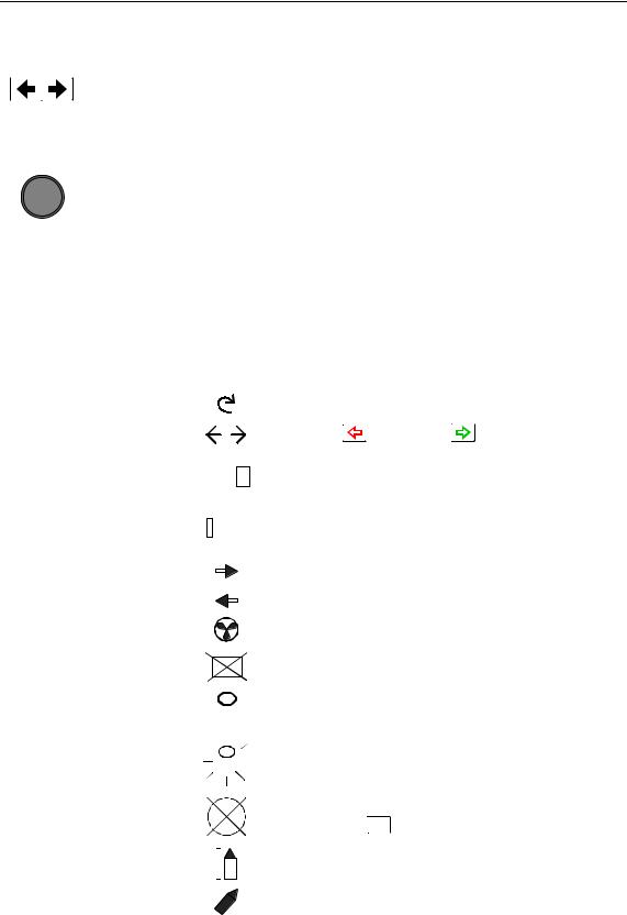
Screen Symbol |
Description |
|
|||||||
|
|
|
|
|
|
|
Rotate course knob |
|
|
|
|
|
|
|
|
|
|
|
|
|
|
|
|
|
|
|
Press |
(PORT) or |
(STBD) button |
|
|
|
|
|
|
|
|
||
04 |
|
|
Rudder angle 4° to starboard |
||||||
|
|
||||||||
|
|
(Rudder command when analog rudder) |
|||||||
|
|
||||||||
|
|
|
|
|
|
|
|
|
|
|
|
02 |
|
Rudder angle 2° to port |
|
||||
|
|
|
|
||||||
|
|
|
(Rudder command when analog rudder) |
||||||
|
|
|
|
|
|
|
|||
|
|
|
|
|
|
|
|
||
|
|
|
|
|
|
|
Rudder command to starboard |
||
|
|
|
|
|
|
|
|||
|
|
|
|
|
|
|
|
|
|
|
|
|
|
|
|
|
Rudder command to port |
|
|
|
|
|
|
|
|
|
|
||
|
|
|
|
|
|
|
|
||
|
|
|
|
|
|
|
Thruster connected to autopilot system |
||
|
|
|
|
|
|
|
|
||
|
|
|
|
|
|
|
Control unit inactive or disengaged |
||
|
|
|
|
|
|
|
|
|
|
|
|
|
|
|
|
|
Control unit locked |
|
|
|
|
|
|
|
|
|
|
||
|
|
|
|
|
|
|
|
||
|
|
|
|
|
|
|
|
|
|
|
|
|
|
|
|
|
|
||
|
|
|
|
|
|
|
Key symbol alternates with mode index on |
||
|
|
|
|
|
|
|
unlocked master unit |
|
|
|
|
|
|
|
|
|
|
||
|
|
|
|
|
|
|
|
||
|
|
|
|
|
|
|
No course changes can be made unless you |
||
|
|
|
|
|
|
|
press the AUTO (AUTO) button |
||
|
|
|
|
|
|
|
|
||
|
|
|
|
|
|
|
Cross track error to starboard |
||
|
|
|
|
|
|
|
|||
|
|
|
|
|
|
|
|||
|
|
|
|
|
|
|
|
|
|
|
|
|
|
|
|
|
Boat turning to starboard |
|
|
|
|
|
|
|
|
|
|
|
|
20221032B |
21 |

Simrad AP50 Autopilot
The control unit shown in Figure 2-1 on page 19 can operate as a stand-alone unit in an autopilot system or it can be combined in a multistation system. In a multistation system, command can easily be transferred from one unit to another and units not in control will display "Inactive".
The autopilot system may also be disabled from the ships’ steering system with an external switch. This will totally disengage the autopilot system from the ships’ main/emergency steering system and the units will display “DISENGAGED”.
The AP50 system is capable of the following primary steering modes with each mode having a dedicated push button: STANDBY (Follow-up and Non-Follow-up), AUTO, NAV and DODGE. AUTO and NAV modes also have a sub-mode that is accessed by pressing the WORK button. The AUTO-WORK and NAV-WORK sub-modes are used under operational conditions different from those normally found when a vessel is in transit on a preset course (e.g. trawling, towing, trolling on one engine, slow speed, using a thruster, etc.).
Each of the mode buttons is clearly identified with the primary function in large text and a secondary function listed in smaller text. Each button provides you with the ability to access a primary display, a secondary display, and/or multiple function displays.
A group of user-adjustable settings belonging to the selected mode are provided in the AP50 User Set-up Menu (see page 38). The settings allow adjustment of display visibility, selection of heading sensor, navigation and position sources, and the ability to select between automatically or manually adjustable sea state filter.
Alarms are presented in plain text to alert you to both system and external data failure conditions. Alarms include both audible and visual presentations. The alarms are listed on page 165.
2.2 ON/OFF - Standby Mode (STBY)
Simrad
AP50
SW V1R2 HW rev. 0
A single press on the STBY (STBY) button switches the system ON and the following status displays are shown:
Autopilot model
Software V(ersion) and R(elease)
Hardware revision
22 |
20221032B |

Operation
Simrad
J50
SW V1R2
P05 M00 S000
Note !
STBY 340.7
Gyro1
RUDDER
02 

ADJUST COMPASS INPUT?
Adjust:
OK? Press  or
or 
Gyro2
Heading 018°
Offset +018°
RUDDER
02 

Stepper or Synchro gyro
STBY 340.7
Gyro1
RUDDER
- -
Analog rudder
Junction unit model
Software V(ersion) and R(elease)
Power board revision, Main board revision and Self check (SW and HW revisions shown are examples only)
After approximately 5 seconds, the system is operative and the unit that was turned on will show the STANDBY mode display. Other units in a multistation system will display "Inactive". Control can be transferred to any single unit by pressing any of its’ mode buttons (except in a Wheelmark system; see the Introduction on page 11).
A long press (3 sec.) on the STBY (STBY) button switches the system off and during this time, the alarm will sound.
In an emergency, it is possible, on a multistation system, to turn
OFF the system at any control unit by pressing the STBY (STBY) button for 3 seconds (except in a Wheelmark system).
STANDBY mode is used when steering the boat at the helm. Display information:
•Standby mode
•Current heading from gyro 1: 340.7°
•Rudder angle: 2° to starboard. When there is no rudder feedback signal (analog rudder drive) the rudder readout shows – –).
If a stepper or synchro gyro is connected to the autopilot system via the GI50 Gyro Interface, a display for the heading adjustment is presented at Power On or at change of compass in the User Set-up menu. Use the course knob to align the autopilot read-out to correspond with the gyro heading. Check the alignment every time the autopilot/gyro is switched on. If two stepper gyros are connected, both will simultaneously be aligned. A stepper gyro used as monitor compass will automatically be aligned to the steering compass.
Press the  (PORT) or
  (STBD) button to proceed to Standby mode.
If the inactive symbol  is shown (when powered up from FU50 or while Disengaged) the Control unit must be activated before alignment by pressing the STBY button.
20221032B |
23 |

Simrad AP50 Autopilot
2.3 AP50 with MSD50 Stern Drive unit
Note !
Note !
STBY 340.7
Gyro1
RUDDER


 10
10
STBY 340.7
Gyro1
RUDDER
00
The information in section 2.3 only applies if your autopilot is driving a Simrad MSD50 Stern Drive.
The MSD50 Stern drive unit has a relative feedback signal which needs a zero point setting after the autopilot has been turned on. Refer to the MSD50 manual for further information.
Zero point setting
If you do not need a rudder angle display when leaving the dock, just steer the boat manually on a straight course and press the AUTO button. The zero point is then set automatically.
If you prefer to use the rudder angle display when leaving the dock, proceed as follows:
After turn on the rudder angle display will alternate between 10 degrees port and starboard to indicate that the "rudder" zero point need be set.
Use the wheel to bring the "rudder" to midship position. Turn the wheel from lock to lock (H.O. to H.O.) and count the exact number of turns. Then start from one lock position and turn the half number of turns.
Press the AUTO button and then the STBY button. The zero point is now set and the following display is shown.
Operation
Follow the operating instructions on the following pages. There is no further need for zero point settings until next time you turn the autopilot on.
24 |
20221032B |
Operation
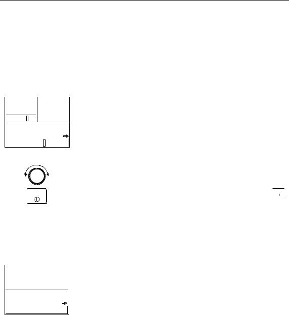
2.4 Follow-Up (FU) Steering
When both the  (PORT) and
  (STBD) buttons are pressed simultaneously, the AP50 will enter Follow-Up steering mode and the course knob may be used to set rudder commands. One revolution of the knob equals a 45° rudder change. The rudder will move to the selected angle and stop.
P FUS |
340.Gyro1 |
7 |
Display information: |
|||||
• |
Follow-Up mode |
|||||||
03 |
|
|
|
|
|
|||
|
|
|
|
|
||||
|
|
|
|
|
|
• Commanded rudder angle: 3° to starboard |
||
RUDDER |
|
|
||||||
|
|
|
|
|
|
• |
Rudder angle: 2° |
|
02 |
|
|
|
|||||
|
|
|
||||||
• The small starboard arrow shows that the rudder is moving. Use the course knob to select the rudder angle.
P S
STBY
Return to manual control in Standby mode by pressing the STBY (STBY) button.
While in Follow-Up mode, you cannot take manual control of the vessel unless you use the External Mode Selector.
2.5 Non-Follow-Up (NFU) Steering
NFU 340.7
340.7
Gyro1
RUDDER
02 

Note !
In STANDBY mode, the NFU display is presented when either the  (PORT) or
  (STBD) button is pressed. The rudder will move as long as the button is pressed and the actual rudder angle is shown on the display. The small arrow shows that the rudder is moving.
When a NFU steering lever or remote control is operated, the control unit(s) become "Inactive".
For safety reasons NFU steering is not possible when an analog rudder is controlled from AD50 Analog Drive
S100 (NFU) Steering Lever
In STANDBY mode, the rudder will move as long as the lever is offset to Port or Starboard.
F1/2 (NFU) Push Button Remote Control
In STANDBY mode, the rudder will move as long as the Port or Stbd button is pressed.
20221032B |
25 |
Simrad AP50 Autopilot
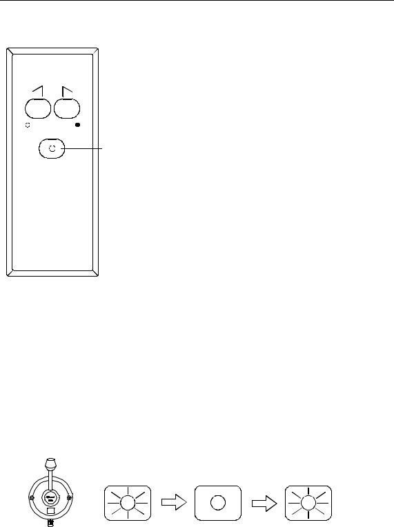
SIMRAD
STBY-AUTO
Simrad R3000X
Note !
R3000X Remote Control (NFU)
Push buttons for Port and 
 Stbd NFU commands
STBY/AUTO mode button. AUTO or NAV mode is when lamp is lit
In STANDBY mode, the rudder will move as long as the Port or Stbd button is pressed.
In AUTO mode the set course will change 1° each time the button is pressed.
Note!
If you keep the button pressed, it will automatically change the course in increments of 3° per second.
Pressing the mode button returns the autopilot to the initial mode, except when in NAV mode:
AUTO → STBY → AUTO AUTO-WORK → STBY → AUTO-WORK NAV → STBY →AUTO
NAV-WORK → STBY → AUTO-WORK
NAV mode can only be entered from a control unit or AP51 Remote Control Unit.
|
S35 NFU Steering Lever |
STANDBY: |
The rudder will move as long as the lever is offset to Port or |
|
Starboard (Non-follow-up steering). |
AUTO/AUTO-WORK: The set course will be changed by 3° per second when the lever is offset to Port or Starboard or 1° for single activation.
The mode button remains lit as long as the autopilot is in AUTO or AUTO-WORK mode (and NAV mode).
The mode change sequence is as follows:
AUTO |
STBY |
AUTO |
AUTO-WORK STBY AUTO-WORK
Pressing the mode button returns the autopilot to the initial mode at the present course.
NAV/NAV-WORK: It is not possible to change the set course by the lever. Pressing the mode button brings the autopilot to STANDBY mode, but the next press brings it to AUTO mode, not back to NAV mode.
26 |
20221032B |

Operation
NAV |
STBY |
AUTO |
|
NAV-WORK |
STBY |
AUTO-WORK |
Note ! |
NAV-WORK mode can only be entered from a control unit or |
||
|
AP51 Remote Control Unit. |
|
|
2.6 Automatic Steering
AUTO Mode
AUTO AUTO mode is used to make the AP50 steer the vessel automatically on a set heading. AUTO mode is always available
from any mode or function within the AP50 by a single push of the AUTO button. When AUTO mode is selected, the AP50 automatically selects the current vessel heading as the set heading and the rudder will move to midship position.
The W Init rudder setting has no effect.
A329
340.7 |
|
|
RUDDER |
|
|
|
|
|
|
|
|
|
02 |
|
|
|
|
||
Gyro1 |
|
|
|
|
|
|
|
|
|
AUTO
In AUTO, the AP50 issues rudder commands to keep the boat on the set heading. The boat heading is provided by the steering compass.
The AP50 will keep the boat on the set heading until a new mode is selected or a new heading is set with either the course knob, the  (PORT) or
  (STBD) buttons, or by pushing the AUTO button again. One revolution of the knob equals a 45° course change.
Once the course is changed to a new set heading, the boat will automatically turn to the new heading and continue to steer straight.
Display information:
•Automatic steering mode
•Set heading: 329°
•Boat heading from gyro compass: 340.7°
•Rudder angle: 2° to port and still moving
Rotate the course knob to change the course: Clock-wise = Starboard course change Counter Clock-wise = Port course change
Press the PORT or STBD button to adjust the course by 1°. It is possible to set the buttons to adjust the course by 5° or 10° per press in the Installation menu (see page 148).
Press the AUTO button to select current vessel heading as set heading.
20221032B |
27 |

Simrad AP50 Autopilot
STBY
WORK
S345Aw
RUDDER
340.7 04
Gyro1
Caution !
Note !
Press the STBY button to regain manual steering
AUTO-WORK Mode
The AUTO-WORK mode is an automatic steering mode to be used under operational conditions different from those normally found when a vessel is in transit on a pre-set course. Examples are trawling, towing, trolling on one engine, slow speed etc.
In such situations, some boats may need different settings. By pressing the WORK button, a separate set of steering and turning values will be used. It can also be set how the rudder should move when entering AUTO-WORK from STANDBY or DODGE.
If W Init Rudder “Actual” is selected (see settings on page 148), the rudder offset is maintained and becomes the Trim value (bumpless transfer).
If W Init Rudder “Midship” is selected, the rudder will move to midship (0°)
When selecting WORK from any automatic mode and when changing between heading and route steering, the rudder offset is always maintained.
To manually change the Trim or other WORK settings, quickly
double press the  (NAV/SETUP) button (see AUTO-WORK mode in the User Set-up menu on page 43).
If Thruster is selected under the Steering function in the User Set-up Menu, the thruster will be used when selecting WORK mode.
Display information:
•AUTO-WORK mode
•Set heading: 329°
•Boat heading from gyro compass: 340.7°
•Rudder offset of 4° to port becomes the Trim value
If you prefer to have complete manual control of the rudder trim in AUTO-WORK mode, the Autotrim can be permanently disabled in the Installation Settings menu (see page 148).
The Off Heading alarm is permanently disabled in AUTOWORK mode.
Pair-trawling requires manual trim only, and the autotrim should be permanently disabled at the Installation Settings menu.
28 |
20221032B |
Loading...