


 Loading...
MANUAL
SIMRAD AP25
Autopilot
20221495F |
Sw.1.3 |
English |

Instruction manual
Instruction Manual
This manual is intended as a reference guide for operating and correctly installing the AP25 autopilot.
Great care has been paid to simplify operation and set-up of the Simrad AP25, however, an autopilot is a complex electronic system. It is affected by sea conditions, speed of the vessel, hull shape and size.
Please take time to read this manual to get a thorough understanding of the operation and system components and their relationship to a complete AP25 autopilot system.
Other documentation material that is included in this manual is a warranty card. This must be filled out by the authorized dealer that performed the installation and mailed in to activate the warranty.
20221495F |
1 |

Simrad AP25 Autopilot
Document history
Rev. A First edition.
Rev. B Minor corrections in text. Table with SimNet/NMEA2000 messages included.
Rev. C FU50 substituted by FU25. Part no. for AC40 Power PCB ass’y, page 136 corrected. Added notes in chapter 3.19. Minor corrections in text and display pictures.
Rev. D Figures 3-6, 3-9, 3-19 and drawing/screen picture on page 39 and 50 corrected. Minor corrections in text. Updated according to autopilot SW 1.2.00
Rev. E Virtual feedback implemented. Minor corrections to text. Applies for SW 1.2.01 and onwards.
Rev. F Correction on page 71, 93 and 150 regarding external alarm on AC10. Use of AT10 for connection of NMEA compass when AC10 is used as autopilot computer, page 90.
2 |
20221495F |
|
|
|
Instruction manual |
|
|
Contents |
|
1 |
System description ....................................................................................... |
9 |
|
|
1.1 |
General .................................................................................................. |
9 |
|
1.2 |
How to use this manual......................................................................... |
9 |
|
1.3 |
System components............................................................................. |
10 |
|
1.4 |
AP25 Control Unit .............................................................................. |
11 |
|
1.5 |
Autopilot Computer ............................................................................ |
11 |
|
1.6 |
RF300 Rudder Feedback unit ............................................................. |
11 |
|
1.7 |
Heading Sensors.................................................................................. |
12 |
|
|
RC36 Rate compass ............................................................................ |
12 |
|
|
RFC35 Electronic Fluxgate Compass (optional)................................ |
12 |
|
|
NMEA compass (optional) ................................................................. |
12 |
|
|
Simrad gyrocompasses........................................................................ |
12 |
|
1.8 |
Optional equipment............................................................................. |
13 |
|
|
R3000X Remote Control .................................................................... |
13 |
|
|
JS10 Joystick....................................................................................... |
13 |
|
|
FU25 Follow-Up Steering Lever ........................................................ |
13 |
|
|
TI25 Thruster Interface ....................................................................... |
13 |
|
|
Multiple stations.................................................................................. |
14 |
|
1.9 |
Software record ................................................................................... |
14 |
2 |
Operation.................................................................................................... |
15 |
|
|
2.1 |
Overview............................................................................................. |
15 |
|
2.2 |
ON/OFF - Standby mode .................................................................... |
16 |
|
|
Flashing course knob icon .................................................................. |
17 |
|
|
Alarms................................................................................................. |
17 |
|
2.3 |
AP25 with MSD50 Stern Drive unit................................................... |
18 |
|
|
Zero point setting ................................................................................ |
18 |
|
2.4 |
Follow-Up steering (FU)..................................................................... |
19 |
|
2.5 |
Non-Follow-Up steering (NFU) ......................................................... |
19 |
|
2.6 |
R3000X Remote Control (NFU)......................................................... |
20 |
|
2.7 |
JS10 Joystick (NFU) ........................................................................... |
20 |
|
2.8 |
Automatic Steering ............................................................................. |
21 |
20221495F |
3 |

Simrad AP25 Autopilot
|
Heading capture .................................................................................. |
21 |
2.9 |
Automatic control of steering parameters........................................... |
22 |
|
Power boat........................................................................................... |
22 |
|
Sailboat................................................................................................ |
23 |
2.10 |
Manual Selection of HI/LO Parameters.............................................. |
23 |
2.11 |
PATTERN steering............................................................................. |
24 |
|
U-turn .................................................................................................. |
24 |
|
C-turn .................................................................................................. |
25 |
|
Spiral-turn ........................................................................................... |
26 |
|
Zigzag-turns ........................................................................................ |
27 |
|
Square-turn.......................................................................................... |
28 |
|
Lazy S-turn.......................................................................................... |
29 |
|
Depth Contour..................................................................................... |
30 |
2.12 |
Dodge in AUTO.................................................................................. |
32 |
2.13 |
Thruster Steering (optional)................................................................ |
33 |
2.14 |
Tacking in Auto mode ........................................................................ |
35 |
2.15 |
NoDrift ................................................................................................ |
35 |
|
Dodge in NoDrift mode ...................................................................... |
36 |
2.16 |
Navigating with the AP25................................................................... |
37 |
|
Setting the waypoint arrival circle ...................................................... |
39 |
2.17 |
Dodge in NAV .................................................................................... |
40 |
2.18 |
Selecting a different Navigation source.............................................. |
41 |
2.19 |
Wind vane steering.............................................................................. |
41 |
2.20 |
Tacking and gybing in Wind mode..................................................... |
43 |
|
Tack and gybe operations ................................................................... |
44 |
|
Tack and gybe prevent ........................................................................ |
44 |
2.21 |
Wind steering and navigation ............................................................. |
45 |
|
Operating in WINDNAV mode............................................................. |
47 |
|
RACING ............................................................................................. |
47 |
2.22 |
Multiple station system ....................................................................... |
48 |
2.23 |
Lock function ...................................................................................... |
48 |
2.24 |
User Set-up Menu ............................................................................... |
50 |
|
Alternating Course Knob Icon ............................................................ |
50 |
|
STANDBY Mode ............................................................................... |
50 |
4 |
20221495F |

|
Instruction manual |
|
|
AUTO Mode ....................................................................................... |
56 |
|
NAV Mode.......................................................................................... |
58 |
|
WIND Mode ....................................................................................... |
58 |
2.25 |
Quick Setup......................................................................................... |
59 |
|
VMG optimizing (RACING).............................................................. |
59 |
|
Layline steering (RACING)................................................................ |
60 |
2.26 |
INFO menu ......................................................................................... |
60 |
|
Course knob icon ................................................................................ |
62 |
|
INFO menu flowchart ......................................................................... |
62 |
|
INFO menu and Main Screen, active unit .......................................... |
63 |
|
INFO menu and Main Screen, inactive or locked unit ....................... |
63 |
3 Installation.................................................................................................. |
65 |
|
3.1 |
General ................................................................................................ |
65 |
3.2 |
Installation checklist ........................................................................... |
65 |
3.3 |
Unpacking and handling ..................................................................... |
66 |
3.4 |
Determine system configuration ......................................................... |
66 |
3.5 |
AP25 System Layout .......................................................................... |
67 |
3.6 |
RF300 Rudder feedback installation................................................... |
67 |
3.7 |
Autopilot computer installation .......................................................... |
69 |
3.8 |
Cable connections ............................................................................... |
70 |
3.9 |
Grounding and RFI ............................................................................. |
70 |
3.10 |
Drive unit installation.......................................................................... |
72 |
|
Connecting a reversible pump ............................................................ |
74 |
|
Connecting a hydraulic linear drive.................................................... |
75 |
|
Connecting a solenoid valve ............................................................... |
75 |
3.11 |
Control unit installation ...................................................................... |
76 |
|
Panel mounting ................................................................................... |
76 |
|
Alternative panel mounting................................................................. |
76 |
|
Optional bracket mounting ................................................................. |
77 |
3.12 |
ROBNET2 network cables ................................................................. |
77 |
|
AP27 connection................................................................................. |
79 |
3.13 |
RC36 Rate Compass installation ........................................................ |
79 |
3.14 |
RFC35 Fluxgate Compass installation ............................................... |
81 |
3.15 |
R3000X Remote Control installation ................................................. |
82 |
20221495F |
5 |

Simrad AP25 Autopilot
|
3.16 |
JS10 Joystick....................................................................................... |
82 |
|
3.17 |
S35 NFU Lever installation ................................................................ |
82 |
|
3.18 |
Interfacing ........................................................................................... |
83 |
|
3.19 |
SimNet................................................................................................. |
83 |
|
|
SimNet network cables ....................................................................... |
84 |
|
|
SimNet power and termination ........................................................... |
84 |
|
3.20 |
Single NMEA input/output................................................................. |
89 |
|
3.21 |
Double NMEA input/output ............................................................... |
89 |
|
3.22 |
NMEA output on Port 2...................................................................... |
90 |
|
3.23 |
NMEA Compass input........................................................................ |
90 |
|
3.24 |
Radar Clock/Data................................................................................ |
91 |
|
3.25 |
IS15 Instrument installation................................................................ |
91 |
|
3.26 |
External Alarm.................................................................................... |
93 |
|
3.27 |
LF3000 Linear Feedback .................................................................... |
93 |
4 |
Configuration and setup ........................................................................... |
95 |
|
|
4.1 |
First time turn on................................................................................. |
95 |
|
4.2 |
Description of Installation Settings..................................................... |
96 |
|
4.3 |
Installation Menu ................................................................................ |
97 |
|
|
Language selection.............................................................................. |
98 |
|
4.4 |
Dockside settings .............................................................................. |
100 |
|
|
Boat type ........................................................................................... |
100 |
|
|
Drive unit voltage.............................................................................. |
101 |
|
|
Rudder Feedback Calibration ........................................................... |
101 |
|
|
Rudder Test ....................................................................................... |
103 |
|
|
Drive engage ..................................................................................... |
105 |
|
|
Rudder Deadband.............................................................................. |
105 |
|
|
Wind setup ........................................................................................ |
106 |
|
|
Minimum wind angle (NORMAL)................................................... |
106 |
|
|
Minimum wind angle (RACING)..................................................... |
107 |
|
|
Tack angle (RACING)...................................................................... |
107 |
|
|
Tack time (RACING)........................................................................ |
107 |
|
|
Wind shift limit (RACING) .............................................................. |
108 |
|
|
Dockside settings when configured for Virtual Feedback................ |
109 |
|
4.5 |
Interface Settings............................................................................... |
113 |
6 |
20221495F |
|
|
|
Instruction manual |
|
4.6 |
Display units ..................................................................................... |
113 |
|
4.7 |
Sea Trial ............................................................................................ |
114 |
|
|
Set Rudder zero................................................................................. |
115 |
|
|
Minimum rudder ............................................................................... |
115 |
|
|
Compass calibration.......................................................................... |
116 |
|
|
Compass Offset ................................................................................. |
118 |
|
|
Set Thrust Direction .......................................................................... |
119 |
|
|
Wind Offset....................................................................................... |
120 |
|
|
Wind damping................................................................................... |
120 |
|
|
Depth Offset...................................................................................... |
121 |
|
|
Automatic tuning............................................................................... |
121 |
|
|
Transition Speed ............................................................................... |
123 |
|
|
Init NAV ........................................................................................... |
123 |
|
|
NAV change limit ............................................................................. |
124 |
|
|
Rudder play compensation................................................................ |
124 |
|
4.8 |
Parameters......................................................................................... |
125 |
|
|
Manual parameter adjust................................................................... |
126 |
|
|
Recall Autotuned?............................................................................. |
128 |
|
4.9 |
Service Menu .................................................................................... |
128 |
|
|
System Data Menu ............................................................................ |
129 |
|
|
SimNet and NMEA Data Screen ...................................................... |
129 |
|
|
NMEA Port test (AC hardware) ....................................................... |
130 |
|
|
Simnet setup...................................................................................... |
131 |
|
|
Master Reset...................................................................................... |
132 |
|
|
Final sea trial..................................................................................... |
132 |
|
|
Providing user training...................................................................... |
133 |
5 |
Maintenance ............................................................................................. |
135 |
|
|
5.1 |
Control unit ....................................................................................... |
135 |
|
5.2 |
Autopilot Computer .......................................................................... |
135 |
|
5.3 |
Rudder Feedback............................................................................... |
135 |
|
5.4 |
Compass ............................................................................................ |
135 |
|
5.5 |
Drive unit .......................................................................................... |
135 |
|
5.6 |
Exchange of software programme .................................................... |
136 |
|
|
Autopilot Computer .......................................................................... |
136 |
20221495F |
7 |

Simrad AP25 Autopilot
|
|
Autopilot Control Unit...................................................................... |
137 |
6 |
Trouble shooting ...................................................................................... |
139 |
|
|
6.1 |
Alarms............................................................................................... |
139 |
7 |
Spare Parts List........................................................................................ |
144 |
|
8 |
Technical Specifications .......................................................................... |
147 |
|
|
8.1 |
AP25 Autopilot System .................................................................... |
147 |
|
8.2 |
AP25 Control Unit ............................................................................ |
149 |
|
8.3 |
Autopilot Computers......................................................................... |
150 |
|
8.4 |
RC36 Rate compass .......................................................................... |
152 |
|
8.5 |
RFC35 Fluxgate compass ................................................................. |
153 |
|
8.6 |
RF300 Rudder Feedback................................................................... |
153 |
|
8.7 |
R3000X Remote Control .................................................................. |
155 |
|
8.8 |
JS10 Joystick..................................................................................... |
155 |
|
8.9 |
FU25 Steering Lever......................................................................... |
156 |
|
8.10 |
IS15 Rudder ...................................................................................... |
157 |
|
8.11 |
SimNet............................................................................................... |
158 |
|
8.12 |
IP protection...................................................................................... |
159 |
|
8.13 |
NMEA and SimNet messages........................................................... |
160 |
9 |
Glossary .................................................................................................... |
164 |
|
10 |
Index.......................................................................................................... |
167 |
|
SALES AND SERVICE WORLDWIDE |
|
||
8 |
20221495F |
System description
1 SYSTEM DESCRIPTION
1.1General
Congratulations on the purchase of your new Simrad AP25 autopilot system and thank you for selecting what we feel is the most advanced autopilot system available on the market today.
Simrad manufactures a complete range of autopilots for all types of vessels, from recreational boats to merchant marine vessels. The company's involvement in autopilots began in 1953 with equipment for the North Sea fishing fleet under the brand name Robertson. Professional mariners around the world acknowledge that the Robertson and Simrad brand names are synonymous with the absolute best in autopilot technology.
The Simrad AP25 autopilot represents yet another step forward in autopilot technology with the intent of providing leisure boats between 30 and 80 foot with a host of new features. Among these the new Virtual Feedback algorithms in the autopilot software enable your autopilot to steer without having to mount a conventional rudder feedback unit.
The autopilot system can be expanded and enhanced with a selection of options and accessories.
The brain in the AP25 autopilot system is the single "intelligent" autopilot computer that communicates on the proprietary Robnet2 network to establish a reliable digital communication and power distribution network between the units in the autopilot system.
The AP25 autopilot is also equipped with the SimNet data and control network. SimNet provides high speed data transfer and control of Simrad products integrated in a total steering and navigation system.
1.2How to use this manual
This manual is intended as a reference guide for operating, installing and maintaining the Simrad AP25 autopilot. Great care has been paid to simplify operation and set-up of the AP25.
Please take time to read this manual to get a thorough understanding of the operation and system components and their relationship to a complete AP25 autopilot system.
20221495F |
9 |
Simrad AP25 Autopilot
Other documentation material that is provided with your system includes a warranty card. This must be filled out by the authorized dealer that performed the installation and mailed in to activate the warranty.
1.3System components
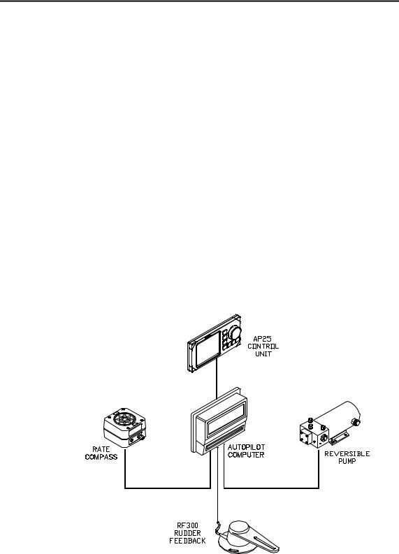
A basic AP25 system consists of the following units (refer to Figure 1-1):
•AP25 Control Unit with accessories
•Autopilot Computer
•Rate compass
•Rudder Feedback Unit with transmission link
•Drive unit
The basic system can be expanded with multiple fixed and hand held full function control units, hand held remote and steering lever.
Figure 1-1 AP25 Basic system
10 |
20221495F |

System description
1.4AP25 Control Unit
A compact autopilot control for panel, bulkhead or bracket mounting. Large LCD 5” display for readout of autopilot data, mode keys and a rotary course knob. It has two Robnet2 connectors for system interconnection and expansion and two SimNet connectors for control and data sharing with other Simrad products. A NMEA2000 Adaptor Cable is available for interface through a SimNet port (page 146).
1.5Autopilot Computer
The autopilot computer is the heart in the AP25 autopilot system. It contains the steering computer, interface to other system components, NMEA 0183 interface and drive electronics for the drive unit motor and clutch. Three models, AC10, AC20 and AC40 are available.
Autopilot computer comparison chart:
|
AC10 |
AC20 (AC40) |
Supply voltage |
10-28 V |
10-40 V |
Motor current (continuous/peak) |
6/12 A |
10/20A (20/40A) |
Clutch/bypass current |
1,5 A* |
1,5 A* |
Number of control units |
2 |
7 |
NMEA 0183 ports (input/output) |
1 |
2 |
Solenoid output |
x |
x |
Input for NFU control |
x |
x |
External alarm |
|
x |
Radar clock/data interface |
|
x |
Input for NMEA compass |
|
x |
*3A on later models
1.6RF300 Rudder Feedback unit
Rudder feedback unit with transmission link and 10 m (30 feet) of cable. Transforms the angular travel of the rudder to a digital signal read by the autopilot steering computer.
20221495F |
11 |

Simrad AP25 Autopilot
1.7Heading Sensors
The AP25 autopilot can be used with the following combinations of heading sensors:
RC36 Rate compass
Fluxgate compass with integrated rate sensor. Provides a dramatic improvement to the dynamic performance of both the autopilot and a stabilized radar display.
RC36 comes as standard with the autopilot.
RFC35 Electronic Fluxgate Compass (optional)
A compact heading sensor from Simrad with 15 m (45 feet) of cable. The direction of the earth's magnetic field is sensed by a floating ring core in a fluxgate coil and transformed to a digital signal read by the autopilot steering computer.
RFC35 can operate as a low cost back-up compass for the AP25 autopilot.
NMEA compass (optional)
A well performing compass that outputs NMEA 0183 HDT or HDG messages at 10 Hz can be connected directly to the AC20 or AC40 autopilot computer.
The AC10 Autopilot Computer has no port for NMEA compass input.
It is absolutely necessary for the autopilot that the heading rate is minimum 10 Hz.
Simrad gyrocompasses
Depending on the model there is direct NMEA0183 interface or you will need an optional GI51 interface unit to get NMEA0183 interface. Ask your Simrad dealer for information.
12 |
20221495F |

System description
1.8Optional equipment
A series of optional equipment are available for the basic AP25 system.
R3000X Remote Control
A small handheld remote control with two push buttons for power steering or course selection (port and starboard), and one push button with built-in lighted indicator for limited mode change.
JS10 Joystick
The JS10 Joystick is a Non-Follow-Up steering lever designed for indoor and outdoor console mount. It has a spring-loaded return-to-mid-position feature and is equipped with 10 m (33’) of cable and installation hardware.
FU25 Follow-Up Steering Lever
Note ! Not applicable for Virtual feedback configuration (page 66).
The FU25 Follow-up steering lever features a dial with 5° rudder angle markings. The rudder will move and stop at the angle selected on the dial. The FU25 has a mid-position indent, buttons for (limited) mode selection, and mode indicators. It is designed for indoor and outdoor bulkhead or flush panel-mounting.
Refer to the FU25 manual for more information.
TI25 Thruster Interface
The TI25 Thruster Interface is designed to provide a control signal for operating a thruster interfaced to an AP25 system. It operates on/off solenoids, or a Danfoss PVEM valve. The Danfoss valve is a proportional valve that will provide full thruster performance with the output from TI25. The thruster output signal is calculated in the TI25 based on the mode of operation and the heading information. Set-up is from the control unit communicated via Robnet2. All settings are stored in the thruster interface unit.
Refer to the TI25 manual.
20221495F |
13 |

Simrad AP25 Autopilot
Multiple stations
Multiple control units can be added to the system. See comparison chart on page 11.
1.9Software record
When the system is switched on, a status display shows the software versions for the control unit and the autopilot computer. See page 16.
Software version |
Description |
SW 1.1.00 |
First issue |
SW 1.2.00 |
NoDrift mode implemented. Easy access to |
|
NAV source selection. Selectable NAV |
|
change limit implemented. Steering |
|
parameters can be changed in Auto mode. |
|
User Setup menu re-edited. Outboard |
|
selectable as boat type in dockside setup. |
|
Improvement in Wind mode algorithms. |
|
Depth contour pattern implemented. New |
|
INFO page showing SOG/Depth. |
SW 1.2.01 |
Virtual feedback implemented. |
SW 1.3.00 |
Anomalies in Setup and in French and |
|
German language repaired. Updated |
|
according to NMEA2000 ver. 1.100. |
Note ! Units with SW 1.2.00 and onwards are not compatible with units with SW 1.1.00.
14 |
20221495F |
Operation
2 OPERATION
WARNING ! An autopilot is a very useful navigational aid, but DOES NOT under any circumstance replace a human navigator.
Do not use automatic steering when:
•In heavy traffic areas or in narrow waters
•In poor visibility or extreme sea conditions
•When in areas where use of autopilot is prohibited by law
When using an autopilot:
•Do not leave the helm unattended
•Do not place any magnetic material or equipment near heading sensor used in the autopilot system
•Verify at regular intervals course and position of vessel
•Always switch to Standby mode and reduce speed in due time to avoid hazardous situations
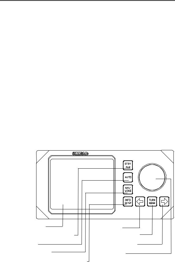
2.1Overview
Multifunction LCD |
PORT key |
STANDBY mode/POWER on/off |
TURN/ DODGE key |
AUTO mode |
STARBOARD key |
NAV or WIND mode |
Course knob |
INSTRUMENT screens/ setup menus |
|
Figure 2-1 AP25 Front Panel
20221495F |
15 |

Simrad AP25 Autopilot
The control unit shown above can operate as a stand alone unit in an autopilot system or combined in a multistation system. In a multistation system the command can easily be transferred from one unit to another. Units not in control will display "Inactive" and/or  .
.
The AP25 system is capable of the following primary steering modes: STBY (power steering), AUTO, NAV and WIND, each mode having a dedicated push button.
Each of the mode push buttons is clearly identified with the primary function in large text, and a secondary function listed in smaller text. Each button provides you with a multiple function mode display.
A group of user adjustable settings are provided in the AP25 User Setup Menu (page 50).
Alarms are presented in plain text to alert you of system and external data failure conditions. Alarms include both audible and visual presentations. The alarm listing is on page 139.
2.2ON/OFF - Standby mode
Note ! At first time turn on see chapter 4.1.
A single press on the STBY button switches the system ON and the following status displays are shown:
Autopilot model
Software version
SimNet no.
Simrad
AP25
SW 1.2.01 HW rev. 00 Sn xxxxxx
Software release Hardware revision
Autopilot computer model
Software version
Power board revision Main board revision
Simrad
AC20
SW 1.2.01
P00 M00 S000 Software release
Self check
SW and HW revisions shown are examples only.
16 |
20221495F |

Operation
After approximately 5 seconds, the system is operative and the unit that was turned on will show the Standby mode display. Other units in a multistation system will display "Inactive". Control is transferred to any single unit by pressing its’ STBY button.
A long press (2-3 sec.) on the STBY button switches the system OFF and during this time, the alarm will sound.
Note ! In an emergency, it is possible, on a multistation system, to turn OFF the system at any control unit by pressing the STBY button for 2-3 seconds.
STBY mode is the mode that is used when steering the boat at the helm.
Display information: − Standby mode
− Current heading 345°
− Rudder angle 1° to starboard.
Note ! When the autopilot operates on Virtual feedback, the numerical indication of the rudder angle is omitted.
Virtual feedback
See pages 67 and 109 about Virtual feedback.
Flashing course knob icon
When the course knob and the PORT/STBD buttons are used for settings etc., an icon will flash on the screen to tell that no course changes can be made unless you press the AUTO button.
Alarms
In the event there is an audible alarm with explaining text on the control unit, refer to section 6, Trouble shooting.
20221495F |
17 |

Simrad AP25 Autopilot
2.3AP25 with MSD50 Stern Drive unit
Note ! The information in section 2.3 only applies if your autopilot is driving a Simrad MSD50 Stern Drive.
The MSD50 Stern drive unit has a relative feedback signal which needs a zero point setting after the autopilot has been turned on. Refer to the MSD50 manual for further information.
Zero point setting
Note ! If you do not need a rudder angle display when leaving the dock, just steer the boat manually on a straight course and press the AUTO button. The zero point is then set automatically.
If you prefer to use the rudder angle display when leaving the dock, proceed as follows:
After turn on the rudder angle display will alternate between 10 degrees port and starboard to indicate that the "rudder" zero point need be set.
Use the wheel to bring the "rudder" to midship position. Turn the wheel from lock to lock (H.O. to H.O.) and count the exact number of turns. Then start from one lock position and turn the half number of turns.
Press AUTO and then STBY. The zero point is now set and the display will show:
Follow the operating instructions on the following pages. There is no further need for zero point settings until next time you turn the autopilot on.
18 |
20221495F |
Operation
2.4Follow-Up steering (FU)
Note ! Not applicable for Virtual feedback configuration (page 67).
In the Follow-Up steering mode the course knob may be used to set rudder commands. The commanded rudder angle is shown on the display and the rudder will move to the commanded angle and stop.
Press both |
Use course |
buttons |
knob to |
simultaneously |
command |
to activate |
rudder angle |
Follow-Up |
|
WARNING ! While in Follow-up mode you cannot take manual control of the wheel.
Return to manual control in Standby by pressing the STBY button
2.5Non-Follow-Up steering (NFU)
In Standby mode, the NFU display is presented when the PORT or STBD button is pressed. The rudder will move as long as the button is pressed and the rudder angle is shown on the display.
|
|
|
|
|
|
|
|
|
|
|
|
|
|
|
|
|
|
|
|
|
|
|
|
|
|
|
|
|
|
|
|
|
|
|
|
|
|
|
|
|
|
|
|
|
|
|
|
|
|
|
|
|
|
|
|
|
|
|
|
|
|
|
|
|
|
|
|
|
|
|
|
|
|
|
|
|
|
|
|
|
|
|
|
|
|
|
|
|
|
|
|
|
|
|
|
|
|
|
|
|
|
|
|
|
|
|
|
|
|
|
|
|
|
|
|
|
|
|
|
|
|
|
|
|
|
Activates |
Activates |
|
||||||||||||||||||
PORT rudder |
STBD |
|
||||||||||||||||||
command |
rudder |
|
||||||||||||||||||
|
|
|
|
|
|
|
|
|
|
command |
|
|||||||||
|
|
|
|
|
|
|
|
|
|
|
||||||||||
Note ! When a NFU steering lever or remote control is operated, other control units become “Inactive”.
20221495F |
19 |
Simrad AP25 Autopilot
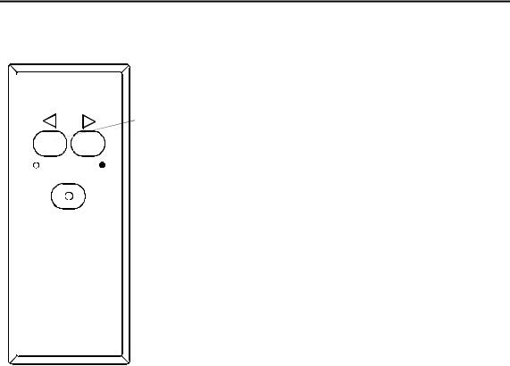
2.6R3000X Remote Control (NFU)
SIMRAD
STBY-AUTO
Simrad R3000X
Notes !
Push button for Port and Stbd commands
STBY/automatic.
Automatic modes are active when the lamp is lit.
In STANDBY mode, the rudder will move as long as the Port or Stbd button is pressed.
In AUTO mode and Wind modes the set course or set wind angle will change 1° each time the button is pressed.
Note!
If you keep the button pressed, it will automatically change the setting in increments of 3° per second.
Mode changes are as per table below.
Initial mode |
1st press |
2nd press |
STBY |
AUTO |
STBY |
AUTO |
STBY |
AUTO |
NAV |
STBY |
AUTO 1)3) |
STBY |
WIND |
STBY 2) |
AUTO |
STBY |
WIND 2) |
WIND |
STBY |
WIND 2) |
WINDN |
STBY |
WIND 3) |
1.When NAV mode is selected in User Setup
2.When WIND mode is selected in User Setup
3.NAV and WINDN modes can only be entered from the Control unit because you have to accept the prompt displays.
2.7JS10 Joystick (NFU)
The principle is similar to that of R3000X Remote Control (see above). The rudder will move as long as the lever is offset to Port or Starboard. JS10 has no mode change feature.
Note ! When a NFU steering lever or a remote control is operated, the control units and FU25 become "Inactive".
20 |
20221495F |
Operation
2.8Automatic Steering
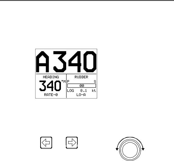
When AUTO mode is selected, the AP25 automatically picks the current boat heading as the set course and maintains the simultaneous rudder angle. This gives a bumpless transfer at the mode change.
Automatic steering mode Set course: 340 degrees Compass reading: 340°M
Heading source: Rate compass Rudder angle: 00°
Speed: 8.1 kt water speed from the log
Steering parameter: LO-A
The AP25 will keep the boat on the set course until a new mode is selected or a new course is set with the course knob or the PORT or STBD buttons. One revolution of the course knob equals a 45° course change.
Decrease Increase |
|
|
Course adjust 1° |
Course change |
|
(or 10°)/ push |
CCW: Decrease |
CW: Increase |
Note ! On power boats it is possible in the User Setup menu to set the buttons to change the course by 10° per press (see page 55)2 .
Once the course is changed to a new set course, the boat will automatically turn to the new heading and continue to steer straight.
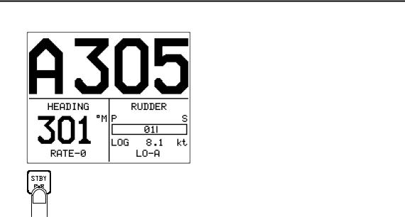
Heading capture
When in AUTO or NoDrift modes this feature allows you to automatically cancel the turn you are in by an instant press on the AUTO or NAV button (NoDrift). The autopilot will counteract the turn and the boat will continue straight ahead on the heading read from the compass the very moment you pressed the AUTO or NAV (NoDrift) button.
20221495F |
21 |
Simrad AP25 Autopilot
Automatic steering mode
New “captured” heading: 305 degrees
Compass reading: 301° M (Magnetic) or
T (True)
Heading source: Rate compass
Rudder angle: 01° to stbd.
Speed: 8.1 kt water speed from the log
Steering parameter: LO-A
Regain manual steering by pressing the STBY button
2.9 Automatic control of steering parameters
The AP25 provides two different sets of steering parameters for controlling the response of the boat at different speeds or wind directions while in AUTO, NAV or WIND modes.
Power boat
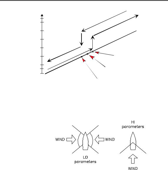
The AP25 selects the LO (response) steering parameters when engaging an automatic mode from STBY provided there is no speed input. This is a safety feature. When entering an automatic mode at low speed, the steering parameters may be changed to HI automatically by input data from a speed log or a GPS navigator, or manually.
The speed at which the AP25 automatically changes from LO to HI parameters (or opposite) is determined by the "Transition Speed" set in the Installation Setup Menu (Sea trial). See diagram below.
Legend
HI-A High response parameters set automatically LO-A Low response parameters set automatically HI-M High response parameters set manually LO-M Low response parameter set manually
22 |
20221495F |
Operation
Speed
26 |
|
|
|
|
|
|
|
|
|
|
|
|
|
|
|
|
|
|
24 |
|
|
|
|
|
|
|
|
|
|
|
|
|
|
|
|
|
|
22 |
|
|
|
|
|
|
|
|
|
|
|
|
|
|
|
|
|
|
20 |
|
|
|
|
|
|
|
|
|
|
|
|
|
|
|
|
|
|
18 |
|
|
|
|
|
|
|
|
|
|
|
|
|
|
|
|
|
|
16 |
|
|
|
|
|
|
|
|
|
|
|
|
|
|
|
|
|
|
14 |
|
|
|
|
|
|
|
|
|
|
|
|
|
|
|
|
|
|
12 |
|
|
|
|
|
|
|
|
|
|
|
|
|
|
|
|
|
|
10 |
|
|
|
|
|
|
|
|
|
|
|
|
|
|
|
rs |
|
|
|
|
|
|
|
|
|
|
|
|
|
|
|
|
|
|
|
||
|
|
|
|
|
|
|
|
|
|
|
|
|
|
|
|
|
||
|
|
|
|
|
|
|
|
|
|
|
|
|
|
|
|
|
|
|
8 |
|
|
|
|
|
|
|
|
|
|
|
ra |
|
te |
|
|
||
|
|
|
|
|
|
|
|
|
|
|
e |
|
|
|
||||
|
|
|
|
|
|
|
|
|
|
|
a |
m |
|
|
|
|
||
6 |
|
|
|
|
|
o |
|
|
p |
|
|
|
|
|
|
|
||
|
|
|
|
|
|
e |
|
|
|
|
|
|
|
|
||||
|
|
|
|
|
|
|
|
s |
|
|
|
|
|
|
|
|
|
|
|
|
|
|
|
p |
n |
|
|
|
|
|
|
|
|
|
|
||
|
|
|
|
s |
|
|
|
|
|
|
|
|
|
|
|
|
|
|
4 |
H |
|
e |
|
|
|
|
|
|
|
|
|
|
|
|
|
|
|
|
|
r |
|
|
|
|
|
|
|
|
|
|
|
|
|
|
|
|
|
I |
|
|
|
|
|
|
|
|
|
|
|
|
|
|
|
|
|
2 |
|
|
|
|
|
|
|
|
|
|
|
|
|
|
|
|
|
|
0 |
|
|
|
|
|
|
|
|
|
|
|
|
|
|
|
|
|
|
|
|
|
|
|
|
|
|
|
|
|
|
|
rs |
|
|
|
|
|
|
|
|
|
|
|
|
te |
|
|
|
|
|
|
|
|
|
|
|
|
e |
|
|
|
|
|
|
|
|
|
|
|
|
m |
|
|
|
|
|
|
|
|
|
|
|
|
a |
|
|
|
|
|
|
|
|
|
|
|
|
|
r |
|
|
|
|
|
|
|
|
|
|
|
|
a |
|
|
|
|
|
|
|
|
|
|
|
|
p |
|
|
|
|
|
|
|
|
|
|
|
|
e |
|
|
|
|
|
|
|
|
|
|
|
|
s |
|
|
|
|
|
|
|
|
|
|
|
|
n |
|
|
|
|
|
|
|
|
|
|
|
|
o |
|
|
|
|
|
|
|
|
|
|
|
|
p |
|
|
|
|
|
|
|
|
|
|
|
|
s |
|
|
|
|
|
|
|
|
|
|
|
|
|
re |
|
|
|
|
|
|
|
|
|
|
|
|
O |
|
|
|
|
|
|
|
|
|
|
|
|
|
L |
|
|
|
|
|
|
|
|
|
|
|
|
|
Transition to LO parameters with increasing speed: 10 Knots
Transition Speed set to 9 Knots
Transition to HI parameters with decreasing speed: 8 Knots
Sailboat
When sailing in WIND mode, the parameters are automatically changed by the direction of the wind as per below or by the boat speed.
The transition between HI and LO parameters and vice versa will have a different characteristics with regards to the wind angle compared with the transition controlled by the speed of the boat.
If you loose too much speed e.g. when tacking, the parameters will change to HI to gain sufficient rudder response. This should be observed when setting the transition speed on sailboats.
2.10Manual Selection of HI/LO Parameters
Manual selection of HI/LO parameters is necessary if there is no speed input to the autopilot or if you want to override the automatic control.
To toggle between LO and HI parameters, press the "AUTO" button two times quickly.
20221495F |
23 |
Simrad AP25 Autopilot
Quick double press
Notes !
1.If you are in NAV or WIND modes you need not enter AUTO mode to manually change the parameter set. Just make a quick double press on the AUTO button.
2.The manually selected setting (HI or LO) will override the automatic selection and remain in effect until you re-enter any automatic mode from STBY.
2.11PATTERN steering
The AP25 offers a number of different pattern steering features when in AUTO mode. The U-turn pattern is always available. Other turn patterns can be selected under the User Set-up 2 menu. Refer to Turn Pattern select on page 55.
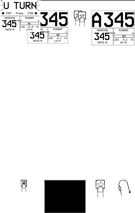
U-turn
This feature is very useful in a man overboard situation and whenever you want to steer back on a reciprocal heading.
U-Turn changes the current set course to be 180 degrees in the opposite direction. The user must decide whether the U-Turn should be made to Port or Starboard when bringing the boat on the new course. U-Turn is activated by a quick press on the TURN/DODGE button. The AP25 will continue on the set course until you press either the PORT or STBD button to select the direction to make the U-Turn. If you do not press PORT or STBD within 1 minute, the AP25 will return to the AUTO mode and stay on course.
Press |
|
Boat makes |
|
TURN/DODGE to |
Select STBD |
||
enter TURN mode |
U-turn |
STBD U- |
|
turn |
|||
|
|
24 |
20221495F |
Operation
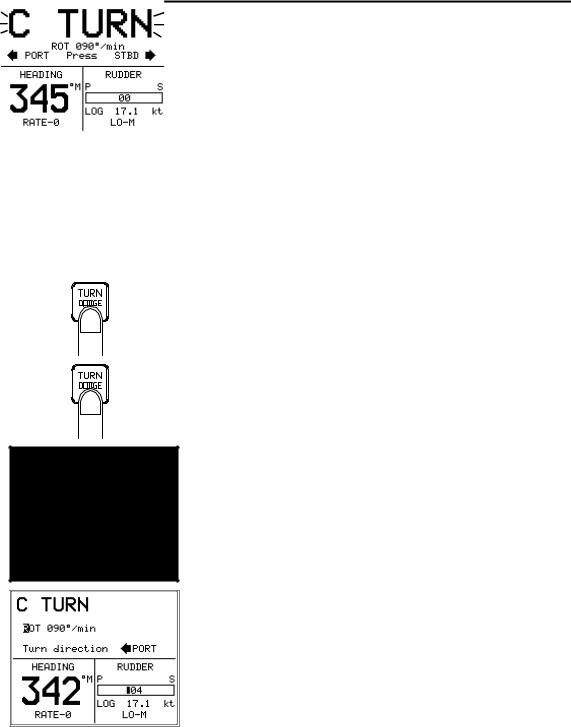
C-turn
The AP25 provides a continuous turn feature when in AUTO mode. This may be used for circling fish or a particular object on the seabed.
C-turn makes the boat turn in a circle with a constant rate of turn. The user decides whether the C-turn should be made to Port or to Starboard.
Ensure that the C-turn pattern has been selected under the User Set-up 2 menu. Refer to Turn Pattern select on page 55.
To enter C-turn mode:
First select U-turn with a press of the TURN/DODGE button.
Then select C-turn by another press of the TURN/DODGE button.
The AP25 will continue on the set course until you press either the PORT or STBD button to select the direction in which to make the C-turn. If you do not press PORT or STBD within 1 minute, the autopilot will return to AUTO mode and stay on course.
The turn rate can be adjusted before the turn is initiated and during the turn. Increasing the turn rate yields to a smaller circle and vice versa.
To exit C-turn mode, press any of the mode buttons. When pressing the AUTO button, the new set course is shown in the upper portion of the display.
Boat turning port
20221495F |
25 |

Simrad AP25 Autopilot
Spiral-turn
The spiral turn feature may also be used for circling fish or when searching a particular object on the seabed.
Spiral-turn makes the boat turn in a spiral with a decreasing or increasing rate of turn. The user decides whether the spiral-turn should be made to Port or Starboard.
Ensure that the Spiral-turn pattern has been selected under the User Set-up 2 menu. Refer to Turn Pattern select on page 55.
To enter Spiral turn mode:
Press the TURN/DODGE button repeatedly until SPIRAL is flashing in the display.
|
|
The initial rate of turn can be adjusted before the turn |
|
||
|
|
is initiated. Increasing the ROT yields to a smaller |
|
|
circle and vice versa. Adjustable range is 10 to |
|
|
600°/min. |
|
|
The AP25 will continue on the set course until you |
|
|
press either the PORT or STBD button to select the |
|
|
direction in which to make the spiral turn. If you do |
|
||
|
|
not press PORT or STBD within 1 minute, the |
|
|
autopilot will return to AUTO mode and stay on |
|
|
course. |
|
|
Select “spiral increase” to move outwards in the |
|
|
spiral and “spiral decrease” to move inwards. Higher |
|
|
number gives a wider spiral. When Spiral 0 the boat |
|
|
will turn in a circle. Range: 0-9. |
Boat turning starboard |
|
|
|
|
Increase 1 |
Increase 5 |
Decrease 1 |
Decrease 5 |
To exit spiral-turn mode, press any of the mode buttons. When pressing the AUTO button, the new set course is shown in the upper portion of the display.
26 |
20221495F |

Operation
Zigzag-turns
A zigzag turn pattern is also available when in AUTO mode.
The user decides whether the first turn should be made to Port or Starboard.
Ensure that the zigzag-turn pattern has been selected under the User Set-up 2 menu. Refer to Turn Pattern select on page 55.
To enter zigzag turn mode:
Press of the TURN/DODGE button repeatedly until ZIGZAG is flashing in the display.
The course change can be set before the turn is initiated. (Range: 2-70°).
The AP25 will continue on the set course until you press either the PORT or STBD button to select the direction in which to make the first course change. If you do not press PORT or STBD within 1 minute, the autopilot will return to AUTO mode and stay on course.
While sailing in a zigzag pattern you can alter the course change (4-140°), time on the leg (1-20 min.), and the set course. An arrow shows the direction of the course change.
Boat turning starboard
Initial course change 20°
Main course
Course change 40° |
Time on leg |
To exit zigzag-turn mode, press any of the mode buttons. When pressing the AUTO button, the new set course is shown in the upper portion of the display.
20221495F |
27 |
Simrad AP25 Autopilot
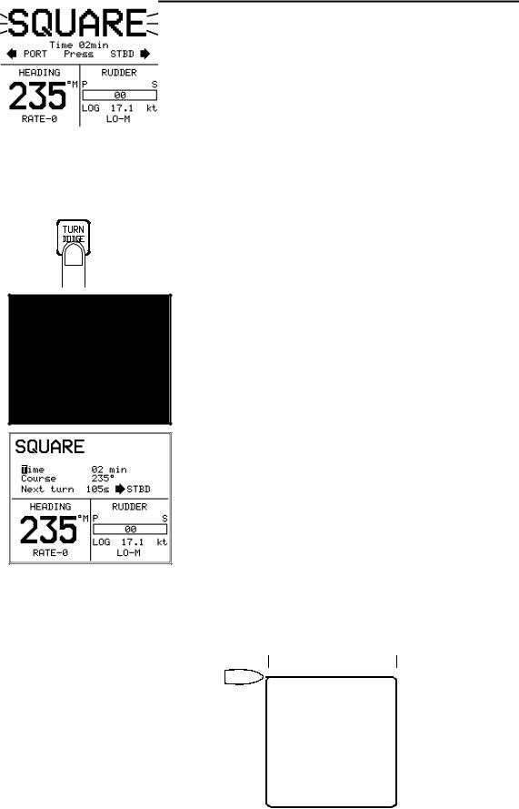
Square-turn
The square turn feature in AUTO mode can also be made a rectangle or any pattern when the next turn is 90°.
The user decides whether the first turn should be to Port or Starboard.
Ensure that the Square-turn pattern has been selected under the User Set-up 2 menu. Refer to Turn Pattern select on page 55.
To enter Square turn mode:
Press of the TURN/DODGE button repeatedly until SQUARE is flashing in the display.
The time between each 90° course change can be adjusted before the turn is initiated (1-30 min.).
The AP25 will continue on the set course until you press either the PORT or STBD button to select the direction in which to make the first course change.
If you do not press PORT or STBD within 1 minute, the autopilot will return to AUTO mode and stay on course.
When the square turn is selected you can change the time between each course change (1-20 min.) hence the length of the leg. While you are on the leg you can also change the time and thus change the shape of the pattern. You can also at any time change the set course.
Boat turning to starboard To exit square-turn mode, press any of the mode buttons. When pressing the AUTO button, the new set course is shown in the upper portion of the display.
Time
28 |
20221495F |
Loading...