

Page 1

Model 5104B
Fire Communicator
Installation and
Operations Manual
Document 151053-L8
05/05/2014 Rev:
P/N 151053-L8-F3 ECN: 14-0068
F3
Page 2

Installation Procedure
Adherence to the following will aid in problem-free installation with long-term reliability:
Installation Precautions - Adherence to the following will aid in problem-free installation with long-term reliability:
WARNING - Several different sources of power can be connected to the fire alarm control panel. Disconnect all sources
of power before servicing. Control unit and associated equipment may be damaged by removing and/or inserti ng card s,
modules, or interconnecting cables while the unit is energized. Do not attempt to install, service, or operate this unit until
manuals are read and understood. CAUTION - System Re-acceptance Test after Software Changes: To ensure proper
system operation, this product must be tested in accordance with NFPA 72 after any programming operation or change in
site-specific software. Re-acceptance testing is required after any change, addition or deletion of system components, or
after any modification, repair or adjustment to system hardware or wiring. All components, circuits, system operations, or
software functions known to be affected by a change must be 100% tested. In addition, to ensure that other operations are
not inadvertently affected, at least 10% of initiating devices that are not directly affected by the change, up to a maximum
of 50 devices, must also be tested and proper system operation verified. This system meets NFPA requirements for
operation within the range of 0°C-49°C (32°F-120°F) or humidity within the range of 10%-93% at 30°C (86°F) noncondensing. However, the useful life of the system's standby batteries and the electronic components may be adversely
affected by extreme temperature ranges and humidity. Therefore, it is recommended that this system and its peripherals be
installed in an environment with a normal room temperature of 15-27º C/60-80º F . Verify that wire sizes ar e adequate for
all initiating and indicating device loops. Most devices cannot tolerate more than a 10% I.R. drop from the specified device
voltage. Like all solid state electronic devices, this system may operate erratically or can be damaged when subjected to
lightning induced transients. Although no system is completely immune from lightning transients and interference, proper
grounding will reduce susceptibility. Overhead or outside aerial wiring is not recommended, due to an increased
susceptibility to nearby lightning strikes. Consult with the Technical Services Department if any problems are anticipated
or encountered. Disconnect AC power and batteries prior to removing or inserting circuit boards. Failure to do so can
damage circuits. Remove all electronic assemblies prior to any drilling, filing, reaming, or punching of the enclosure.
When possible, make all cable entries from the sides or rear. Before making modifications, verify that they will not
interfere with battery, transformer, or printed circuit board location. Do not tighten screw terminals more than 9 in-lbs.
Over-tightening may damage threads, resulting in reduced terminal contact pressure and difficulty with screw terminal
removal. fire alarm control panels contain static-sensitive components. Always ground yourself with a proper wrist strap
before handling any circuits so that static charges are removed from the body. Use static suppressive packaging to protect
electronic assemblies removed from the unit.
Follow the instructions in the installation, operating, and programming manuals. Th ese instructions must be followed to
avoid damage to the control panel and associated equipment. Fire Alarm Control Panel (FACP) operation and reliability
depend upon proper installation.
While installing a fire alarm system may make lower insurance rates possible, it is not a substitute for fire insurance! An
automatic fire alarm system - typically made up of smoke detectors, heat detectors, manual pull stations, audible warning
devices, and a fire alarm control with remote notification capability - can provide early warning of a developing fire. Such
a system, however, does not assure protection against property damage or loss of life resulting from a fire. Any fire alarm
system may fail for a variety of reasons: Smoke detectors may not sense fire where smoke cannot reach the detectors such
as in chimneys, in walls, or roofs, or on the other side of closed doors. Smoke detectors also may not sense a fire on
another level or floor of a building. A second floor detector, for example, may not sense a first floor or basement fire.
Furthermore, all types of smoke detectors, including ionization and photoelectric types, have sensing li mitations. No type
of smoke detector can sense every kind of fire caused by carelessness and safety hazards like smoking in bed, violent
explosions, escaping gas, improper storage of flammable materials, overloaded electrical circuits, children playing with
matches, or arson.
IMPORTANT! Smoke detectors must be installed in the same room as the control panel and in rooms used by the
system for the connection of alarm transmission wiring, communications, signaling, and/or power. If detectors are not so
located, a developing fire may damage the alarm system, crippling its ability to report a fire. Audible warning devices
such as bells may not alert people if these devices are located on the other side of closed or partly open doors or are located
on another floor of a building. A fire alarm system will not operate without any electrical power. If AC power fails, the
system will operate from standby batteries only for a specified time. Rate-of-Rise heat detectors may be subject to
reduced sensitivity over time. For this reason, the rate-of-rise feature of each detector should be tested at least once per
year by a qualified fire protection specialist. Equipment used in the system may not be technically compatible with the
control. It is essential to use only equipment listed for service with your control panel. Telephone lines needed to transmit
alarm signals from a premise to a central monitoring station may be out of service or temporarily disabled. The most
common cause of fire alarm malfunctions, however, is inadequate maintenance. All devices and system wiring should be
tested and maintained by professional fire alarm installers following written procedures supplied with each device. System
inspection and testing should be scheduled monthly or as required by national and/or local fire codes. Adequate written
records of all inspections should be kept.
Page 3

Contents
Section 1
Introduction ..............................................................................................................................................1-1
1.1 Feature ......................................................................... ............................................................1-1
1.2 Accessory Devices ...................................................................................................................1-1
1.3 About This Manual ...................................................................................................................1-1
1.3.1 How to Use This Manual ...................................................................................................1-2
Section 2
Agency Requirements ............................................................................................................... 2-1
2.1 Telephone Requirements .........................................................................................................2-1
2.2 FCC Warning ............................................................................................................................2-2
2.3 UL Requirements .....................................................................................................................2-2
2.4 Canadian Department of Communications ..............................................................................2-2
Section 3
Installation ................................................................................................................................................. 3-1
3.1 Electrical Specifications ................... ... ......................................................................................3-1
3.2 Environmental Specifications .......................... ... ... .... ... .......................................... ..................3-1
3.3 Wiring Specifications ................................................................................................................3-2
3.4 Panel Description .....................................................................................................................3-2
3.4.1 Terminal Description ..........................................................................................................3-4
3.4.2 LED Descriptions ...............................................................................................................3-5
3.4.2.1 Externally Visible LEDs (L3, L4, & L5) .....................................................................3-5
3.4.2.2 Phone Line Fault Indicator LEDs (L6 &L7) ............................. ... ... ... .... ... ... ... ... .... ... ..3-5
3.4.2.3 Overcurrent LED Indicators (L1 & L2) ......................................................................3-6
3.4.3 Reset / Silence Switch .......................................................................................................3-6
3.4.4 Cable Connectors (P1, P2, and P3) ..................................................................................3-6
3.4.5 On-board Piezo Sounder ...................................................................................................3-6
3.5 Calculating Current Draw and Standby Battery ........................................................................3-7
3.5.1 Worksheet Requirements ..................................................................................................3-7
3.5.1.1 Maximum Battery Standby Load .............................................................................. 3-7
3.5.2 Current Draw Worksheet ...................................................................................................3-8
3.6 Mounting the 5104 Cabinet ......................................................................................................3-9
3.6.1 Preventing Water Damage ................................................................................................3-9
3.7 Mounting the 5104 PC Board ...................................................................................................3-9
3.8 AC Connection ......................... .... ... ... ... ... .... ... ... ... .... ...................................... .... ... ... ... ..........3-10
3.8.1 Standard Transformer Connections ................................................................................3-10
3.9 Battery Connection .................................................................................................................3-10
3.10 Detector Installation ................................................................................................................3-12
3.10.1 Class A (Style D) Zones ................................................................................................3-12
3.10.2 Class B (Style B) Zones ...............................................................................................3-12
3.10.3 Four-Wire Smoke Detector Connection ........ .... ...................................... .... ... ... ... ... .... ...3-13
3.11 Supplemental Notification Appliance Installation ............. ... .... ... .............................................3-14
3.11.1 Non-Supervised Notification Appliance Wiring ..............................................................3-15
151053-L8 i
Page 4

3.11.2 Supervised Notification Appliance Wiring ...................... ................................................ 3-16
3.12 Telephone Line Connections ..................................................................................................3-17
3.13 Model 5230 Installation ................................... ... ... ....................................... ... .... ... ... ... ..........3-18
3.13.1 Mounting the 5230 .........................................................................................................3-18
Section 4
Add-on Fire Communicator Application ...........................................................4-1
Section 5
5230 Operation .....................................................................................................................................5-1
5.1 5230 Display Messages ........................... .... ... ... ....................................... ... ... .... ... ... ... ............5-1
5.2 5230 Touchpad Functions .................................. ... ....................................... ... .... ... ... ... ... .... .....5-2
Section 6
Programming .........................................................................................................................................6-1
6.1 UL 864 Programming Requirements ...................................... ................................................ ..6-1
6.2 5230 Programming ............................. ... ... .... ... ... ... .... ... ... ....................................... ... ... ... .........6-1
6.2.1 Default User Codes ...........................................................................................................6-1
6.2.2 How to Enter and Exit Program Mode ...............................................................................6-1
6.2.3 How to Enter Program Mode .............................................................................................6-2
6.2.4 How to Exit Program Mode ............. ... .... ... ... ... ....................................... ... .... ... ... ... ... .........6-2
6.2.5 Step Programming .............................................................................................................6-2
6.2.6 Maneuvering in Program Mode .........................................................................................6-2
6.2.6.1 Entering Selected Values ................................ ... .... ... ... ... ... .... ... ... ............................6-2
6.2.6.2 Bypass a Step ..........................................................................................................6-3
6.2.6.3 Go to a Step ........................................................... ... ... ... ... .... ... ... ............................6-3
6.2.7 Programming Steps ...........................................................................................................6-3
Section 7
Reporting .....................................................................................................................................................7-1
7.1 Reporting Formats ....................................................................................................................7-1
7.2 Reporting Codes ......................................................................................................................7-2
Section 8
Troubleshooting ................................................................................................................................8-1
Silent Knight Fire Product Warranty and Return Policy
Manufacturer Warranties and Limitation of Liability
151053-L8 ii
Page 5

Section 1 Introduction
The Model 5104 is a low-cost fire communicator that meets the requirements for NFPA 72, UL 864, MEA,
CSFM, and FM.
1.1 Feature
• Six supervised fire zones, consisting of one Class A (Style D) and five Class B
(Style B) zones.
• Current limited loop power output for the Class B zone inputs.
• Ground fault detection.
• Built-in piezo sounder for trouble and supervisory conditions.
• Reset/Silence switch that performs the following:
1 Silences troubles and alarms.
2 Resets smoke detector power .
3 Resets accessory power.
151053-L8
• Supervision of Reset/Silence switch. If the switch is depressed for 15 seconds or longer, an audible trouble
signal will occur. See section 3.4.3
• 24 hour battery backup from a 12 VDC, 7 Ah rechargeable battery.
• Separate battery charging circuit that maximizes battery life.
• Multiple reporting formats (SIA, SK 3/1, Sescoa 3/1, Contact ID, SK 4/2, Radionics BFSK).
• Programmable relay output provides additional annunciation for either alarm or dialer-failed condition.
• Three LEDs indicating AC power (green) status, Trouble Silenced (yellow), and Dialer Failed (yellow).
• Four LEDs inside cabinet indicate short circuits and trouble conditions.
• Easy, English-language programming using the 5230 Remote Annunciator.
• Versatile two-number dialing feature for reporting to two different numbers.
• Programmable dialing format (rotary or Touch Tone).
• Two phone line monitoring and seizure circuits.
• Transient Voltage protection on all inputs (AC, phone lines, accessory zones).
• Automatic daily test.
• EEPROM memory storage of all programmed information.
1.2 Accessory Devices
• Model 5230 Remote Annunciator (optional). Used for system control, programming and troubleshooting.
• Model 7860 modular cable with spade lugs for connection to Telco RJ31X plug (optional).
1.3 About This Manual
This manual is intended for those persons involved with the installation and maintenance of the 5104 Fire
Communicator. It is a comprehensive guide providing detailed instructions, and should be kept for reference. As
1-1
Page 6

Model 5104B Installation Manual 151053-L8
much as possible, we have tried to organize the manual chronologically by the tasks that need to be performed.
Please let us know if the manual does not meet your needs in any way.
1.3.1 How to Use This Manual
In this manual, the following conventions are used:
• Pages of the manual are numbered by section. For example, a page numbered as 5-1 is page 1 of Section 5.
• Text in this type face indicates a 5230 display message:System Normal.
1-2
Page 7

151053-L8
Section 2 Agency Requirements
This section list all the requirements for the 5104 by agency.
Install and maintain in accordance with NFPA 72. Detector spacing shall be in accordance to NFPA 72. End-of -
line relays and resistors shall be placed within the electrical box located and the end of the initiating circuit.
Testing and maintenance should be performed according to NFPA 72.
2.1 Telephone Requirements
If requested by telephone company the following information must be provided before connecting this device to
the phone lines:
A. Manufacturer: Silent Knight
B. Model Number: 5104B
C. FCC Registration Number: AC698R-17462-AL-E
D. Type of jack (to be installed by the
telephone company):
Ringer equivalence: 0.1B
This device may not be directly connected to coin operated telephones or party line services.
This device cannot be adjusted or repaired in the field. In case of trouble with device, notify the installing
company or Silent Knight for an RA number and then return it to:
Silent Knight
12 Clintonville Road
Northford, CT 06472-1610
800-328-0103 or 203-484-7161
If the Model 5104 causes harm to the telephone network, the telephone company will notify the user in advance
that temporary discontinuance of service may be required. If advanced notice is not practical the telephone
company will notify the customer as soon as possible. You as the user have the right to file a complaint with the
Federal Communications Commission if you believe it is necessary.
The telephone company may make changes in its facilities, equipment, operations, or procedures that could
affect the operation of the equipment. If this happens, the telephone company will provide advance notice to
allow you to make the necessary modifications to maintain uninterrupted service.
RJ31X
2-1
Page 8

Model 5104B Installation Manual 151053-L8
2.2 FCC Warning
Warning
This device has been verified to comply with FCC Rules Part 15. Operation is subject to the following
conditions: (1) This device may not cause radio interference, and (2) This device must accept any
interference received, including interference that may cause undesired operation.
2.3 UL Requirements
The 5104 is UL listed as a Control Unit for use in Central Station Fire-Protective Signaling Systems (UL864,
NFPA 72). All UL installations must comply with the following requirements:
1. The 120 VAC wiring to the 5104 cabinet must be enclosed in conduit.
2. Total standby current must not exceed 275 mA for central station use or 105 mA for remote station use.
3. Remote station installations must not attach any current drawing devices. This includes 5230 Remote
Annunciator.
4. All electrical connections must comply with ratings shown in Section 3.
Restricted Options:
• The loss of AC signal is defaulted to 3 hours however the system allows settings from 0 - 30 hours. For UL
certified installations this number must be set from 1 to 3 hours.
• Call forwarding shall not be used.
2.4 Canadian Department of Communications
The Canadian Department of Communications label identifies certified equipment. This certification means that
the equipment meets certain telecommunications network protective, operational and safety requirements. The
Department does not guarantee the equipment will operate to the user’s satisfaction.
Before installing this equipment, users should ensure that it is permissible for the equipment to be connected to
the facilities of the local telecommunications company. In some cases, the company’s inside wiring associated
with a single line individual service may be extended by means of a certified connector assembly (telephone
extension cord). The customer should be aware that compliance with the above conditions may not prevent
degradation of service in some situations.
Repairs to certified equipment should be made by an authorized Canadian maintenance facility designated by the
supplier. Any repairs or alterations made by the user to this equipment; or equipment malfunctions, may give the
telecommunication company cause to request the user to disconnect the equipment.
Users should ensure for their own protection that the electrical ground–connections of the power utility,
telephone lines and internal metallic water pipe system, if present, are connected together. This precaution may
be particularly important in rural areas.
CAUTION: Users should not attempt to make such connections themselves, but should contact the appropriate
electric inspection authority, or electrician, as appropriate.
2-2
Page 9

Section 3 Installation
This section contains information necessary to install the 5104 Fire Communicator and accessories.
3.1 Electrical Specifications
Primary AC 120 Vrms @ 60Hz, 374 ma
Total DC load 1.3 Amp
Accessory Power 12 VDC @ 750 mA
Phone Line Voltage 2.75 VDC min.
Smoke Power 12 VDC @ 750 mA
Battery Charging Voltage 13.8 VDC
Minimum Low Battery Detection 10.2 VDC
Minimum Low AC Detection 102 Vrms @ 60 Hz, full load
Auxiliary Notification Appliance Circuit 12 VDC @ 500 mA
151053-L8
3.2 Environmental Specifications
It is important to protect the 5104 panel from water. To prevent water damage, the following precautions should
be FOLLOWED when mounting the unit:
• Mount indoors in dry locations only
• Do not mount directly on exterior walls, especially masonry walls (condensation).
• Do not mount directly on exterior walls below grade (condensation).
• Protect from plumbing leaks.
• Protect from splash caused by sprinkler system inspection ports.
• Do not mount in areas with humidity-generating equipment (such as dryers, production machinery, etc.).
• Operating temperature range is 32° to 120° F (0° to 49° C).
• Indoor use only.
• 10% to 93% non-condensing humidity at 30°C (86°F).
• Non-corrosive environment.
3-1
Page 10

Model 5104B Installation Manual 151053-L8
3.3 Wiring Specifications
Induced noise (transfer of electrical energy from one wire to another) can interfere with telephone
communication or even cause false alarms. T o avoid induced noise, follow these guidelines:
• Isolate input wiring from high current output and power wiring. Do not pull one multi-conductor cable for
the entire panel. Instead, separate the wiring as follows:
High Voltage AC Power
Audio input/output Phone Line Circuits, Terminals 13-20
Notification Circuits Terminals 21-22
Data Communication Circuits Terminals 25-26
• Do Not pull wires from different groups through the same conduit. If you must run them together, do so for
as short a distance as possible or use shielded cable. Connect the shield to earth ground at the panel only.
• High frequency noise, such as that produced by the inductive reactance of a speaker or bell, can also be
reduced by running the wire through ferrite shield beads or by wrapping it around a ferrite toroid.
• Route the wiring around the inside perimeter of the cabinet. It should not cross the circuit board where it
could induce noise into the sensitive microelectronics of pick up unwanted RF noise from the high speed
circuits. See Figure 3-1 for an example.
Figure 3-1 Wire Routing Example
3-2
Page 11

Installation 151053-L8
T erminal
Block 1
T erminal
Block 3
Terminal
Block 2
P1
P2
L3
L4
L5
L7
L6
Reset/
Silence
Switch
Terminal
Block 4
P3
L1
L2
3.4 Panel Description
This section describes the 5104 board components, including terminal strips, LEDs, Switches and cable
connectors. See Figure 3-2.
Figure 3-2 5104 Circuit Board
3-3
Page 12

Model 5104B Installation Manual 151053-L8
3.4.1 Terminal Description
Table 3-1 lists the terminals by number and describes the terminals use.
Table 3-1: Terminal Description by Terminal Block
Terminal
Block #
1
2
3
4
T erminal # Description
1 Loop A output (Class A Style D)
2 Loop B output 0
3 Loop B input 0
4 Loop A input 0
5 Input (Class B Style A)
6 Power (Power Limited) 0
7 Circuit Ground 0
8 Input (Class B Style A)
9 Power (Power Limited) 0
10 Input (Class B Style A)
11 Power (Power Limited) 0
12 Circuit Ground 0
13 Telco Ring
14 Telco Tip N/A
15 House Ring N/A
16 House Tip N/A
17 Telco Ring
18 Telco Tip N/A
19 House Ring N/A
20 House Tip N/A
21 Bell (+) positive
22 Bell (-) negative 0
23 Ground
24 Accessory Power (Power Limited) 0
25 Serial Data Out (Power Limited) 0
26 Serial Data In 0
27 Input (Class B Style A) Zone 5
28 Power Zone 5 & 6 0
29 Input (Class B Style A) Zone 6 0
Zone 1
Zone 2
Zone 3
Zone 4
Phone Line
1
Phone Line
2
Notification
Circuit
5230
Annunciator
(Optional)
Electrical
Specification
(Power Limited) 0
(Power Limited) 0
(Power Limited)
Earth Ground
Impedance
(in Ohms)
0
0
0
N/A
N/A
0
0
3-4
Page 13

Installation 151053-L8
3.4.2 LED Descriptions
This section describes what each LED indicates. The 5104 has a total of seven LEDs, three are visible externally
and four are visible only if the cabinet door is open. See Section 8 for additional information on LED operation.
3.4.2.1 Externally Visible LEDs (L3, L4, & L5)
This section describes the three LEDs (one green and two yellow) that are visible externally through the window
on the 5104 cabinet door. Refer to Table 3-2 and Figure 3-2.
Table 3-2: Externally Visible LEDs
LED # Name Color Description
L3 Power Green
L4 Silenced Yellow
L5 Dialer Yellow
Normally ON unless the panel loses AC power or the panel is
being reset.
Normally OFF unless a trouble or supervisory condition has
been silenced.
Normally OFF unless there is a phone line or communication
problem. See Section 3.4.2.2 for additional information.
3.4.2.2 Phone Line Fault Indicator LEDs (L6 &L7)
The 5104 has a built-in dual-phone line monitoring circuit. This circuit detects any fault in the phone line by
monitoring the loop current and DC voltage. If the phone line drops to 1.8 VDC @ 5 mA or below for 40 to 90
seconds the on-board piezo and the corresponding LED will turn ON. The control panel will then report the fault
condition to the central station on the other phone line. For example, if phone line one looses phone line voltage,
the on-board piezo and the L6 will turn on, then the control panel will report the faulted line on phone line two.
See Figure 3-2 for LED Locations
Note: To comply with NFPA 72 the model 5104 is equipped with phone line seizure. This means that any time the
control panel dialer needs to communicate with the central station, it will not be possib le to use the telephones that are on the same line as the fire system. During communication to the central station the phone
lines will be seized for approximately one minute. However, under adverse telephone circuit conditions
phone line seizure could last as long as 15 minutes.
Table 3-3: Phone Line Fault Indicator LEDs
LED # Name Color Description
L6 Phone Line 1 Fault Red
L7 Phone Line 2 Fault Red
Visible only when the 5104 cabinet is open. If ON indicates
that phone line 1 is faulted. A faulted condition is indicated if
the phone line voltage drops below 1.8 VDC and the loop
current is less than 5 mA. Flashing indicates a communication
error has occurred.
Visible only when the 5104 cabinet is open. If ON indicates
that phone line 2 is faulted. A faulted condition is indicated if
the phone line voltage drops below 1.8 VDC and the loop
current is less than 5 mA. Flashing indicates a communication
error has occurred.
3-5
Page 14

Model 5104B Installation Manual 151053-L8
3.4.2.3 Overcurrent LED Indicators (L1 & L2)
The 5104 has two red LEDs which indicate if excessive current is being drawn by a device connected to either
the Accessory Power or Smoke Power circuits. Table 3-4 lists the two overcurrent LEDs and gives a description
of them. See Figure 3-2 for LED locations.
Table 3-4: Overcurrent LED Description
LED # Name Color Description
L1
L2 Smoke Power Fault Red
If either L1 or L2 turn on disconnect power immediately. Refer to Section 8 for troubleshooting information.
Accessory Power
Fault
Red
If a device connected to the accessory power circuit draws
more than 750 mA the overcurrent poly fuse will open and L1
will turn on.
If a device connected to the smoke power circuit draws more
than 750 mA the overcurrent poly fuse will open and L2 will
turn on.
3.4.3 Reset / Silence Switch
The Reset/Silence switch has three functions:
• Silences audible trouble, or supervisory signals. A trouble or supervisory piezo annunciation will be silenced
immediately when you press the switch.
Note: If the switch is depressed for 15 seconds or longer an audible trouble signal will occur
• Resets smoke detector power. This function removes power from terminals 6, 9 and 11.
Note: To reset smoke detector power, depress the reset /trouble switch for a minimum of 1 second.
• Reset accessory powered devices. This function removes power from terminal 24.
Note: To reset accessory powered devices depress the reset/silence switch for a minimum of 1 second
The Reset/Silence switch is accessible inside the panel (DO NOT install the switch extender provided with the
system) for UL certified installations.
3.4.4 Cable Connectors (P1, P2, and P3)
There are two connectors on the 5104 (see Figure 3-2 for P1 and P2 locations). The function of these connectors
is as follows:
Connector Function
P1 Connects the wires from the secondary winding of the AC transformer
to the control panel. (See Section 8 Troubleshooting for additional
information.
P2 Used as a quick-connect for the 5230 Remote Annunciator to do
programming or troubleshooting.
P3 Standby battery connector.
3.4.5 On-board Piezo Sounder
The on-board piezo sounder gives an audible output for troubl e, and supervisory conditions. Troubles and
supervisories can be silenced with the Reset/Silence switch immediately.
3-6
Page 15

Installation 151053-L8
3.5 Calculating Current Draw and Standby Battery
This section should be used to help you determine the current draw and standby battery needs for your
installation.
3.5.1 Worksheet Requirements
The following steps must be taken when determining the 5104 current draw and standby battery requirements.
Fill in the Current Draw Worksheet (Table 3-6) in section 3.5.2.
For the 5104, the worst case current draw is listed in Table 3-6 for the panel and accessory devices.
Follow these steps to properly fill in the Current Draw Worksheet.
1. Fill in the number of devices used.
2. Compute the current draw requirements for alarm and standby and record this data into line A.
3. Add up the current draw for all the smoke detectors and record the totals in line B.
4. Total all the notification appliance device loads and enter that number into line C.
5. Make sure that the alarm current you calculated, including current for the panel itself, does not exceed 750
mA. This is the maximum current allowable.
6. Complete the remaining instructions in Table 3-6 to determine battery size requirements.
3.5.1.1 Maximum Battery Standby Load
Table 3-5 shows the maximum battery st andby load for the 5104 based on 24 and 60 hours of standby. the
standby load calculations of line D in Table 3-6 must be less than the number shown in Table 3-5 for the battery
size used and standby hours required.
Table 3-5: maximum Battery Standby Load
Rechargeable Battery
Size
7 AH 275 mA 105 mA
Maximum Load for 24
hrs. Standby, 5 min.
Alarm
Maximum Load for 60
hrs. Standby, 5 min.
Alarm
3-7
Page 16

Model 5104B Installation Manual 151053-L8
3.5.2 Current Draw Worksheet
Use this worksheet to determine current requirements during alarm/battery standby operation.
Table 3-6: Current Draw Calculations
Device
For each device use this
formula:
5104 1
5230 3 max
A Current Subtotals: mA mA
Smoke Detectors
B Current Subtotals: mA mA
Notification Appliances
C Current Subtotals:
D Total current rating of all devices in system (add totals of A-C) x .001: A A
E Number of standby hours. (24 or 60 for NFPA 72, chapter 1, 1-5.2.5): H
F Multiply lines D (standby current) and E. Total standby AH AH
G Alarm sounding period in hours. (For example, 5 minutes = .0833 hours) H
H Multiply lines D (alarm Current) and G totals Total alarm AH
I Add lines F and H. AH = Ampere Hours Tot al AH req uired AH
Number of
Devices
This Column
Current per Device
x This Column = Current per number of
Standby: 75 mA 75 mA
Alarm: 135 mA 135 mA
Standby: 25 mA mA
Alarm: 40 mA mA
Standby: mA mA
Alarm: mA mA
Standby: mA mA
Alarm: mA mA
Standby: mA mA
Alarm: mA mA
Standby: mA mA
Alarm: mA mA
Standby: mA mA
Alarm: mA mA
Standby: mA mA
Alarm: mA mA
Standby
Current
devices
Alarm
Current
mA
mA
mA
mA
mA
mA
AH
3-8
Page 17

Installation 151053-L8
3.6 Mounting the 5104 Cabinet
Read the environmental specifications in Section 3.2 before mounting the 5104 cabinet. This will ensure that you
select a suitable location.
The panel should be accessible to main drop wiring runs. It should be mounted as close to the center of the
building as possible and located within a secured area, but should be accessible for testing and service.
When mounting on interior walls, use appropriate screw anchors in plaster. When mounting on concrete,
especially when moisture can accumulate, the enclosure shall be placed or equipped so as to prevent moisture or
water from entering and accumulating within the cabinet, and shall be mounted so there is a least 1/4” space
between the enclosure and the concrete wall surface. A piece of plywood, standoffs, or other equivalent material
can be used to space the cabinet from the concrete surface and then attach the 5104B to that spacing surface. Also
mount any other desired components to the 1/4” spacing surface.
DO NOT flush-mount the 5104B cabinet in a wall designated as a fire break.
3.6.1 Preventing Water Damage
Water damage to the fire system can be caused by moisture entering the cabinet through the conduits. Conduits
that are installed to enter the top of the cabinet are most likely to cause water problems. Installers should take
reasonable precautions to prevent water from entering the cabinet. Water damage is not covered under warranty.
3.7 Mounting the 5104 PC Board
Since the 5104 panel ships with the PC board installed, this section is intended only for installations in which the
5104 PC board is being replaced. Line up the four PC board mounting holes with the four standoffs in the cabinet
as shown in Figure 3-3, and use four mounting screws to secure the board to the cabinet.
Figure 3-3 Mounting the 5104 PC Board
3-9
Page 18

Model 5104B Installation Manual 151053-L8
Green
Ground Wire
Red
Transformer Wires
AC Plug
Replace battery
Every 5 years
3.8 AC Connection
3.8.1 Standard Transformer Connections
The AC transformer is factory mounted into the control panel and is plugged onto the control panel as shown in
Figure 3-4. The ground and the primary side of the transform e r shoul d be wired as shown in Figure 3-4 by a
certified electrician.
Figure 3-4 AC Transformer Connections
3.9 Battery Connection
The battery provides backup power to the system during AC power loss. Connect the 12 VDC battery (SK Model
6712) as shown in Figure 3-5.
Figure 3-5 Backup Battery Connections
Note: Observe proper polarity when connecting the 12 VDC battery to 5104. If polarity is reversed, a resettable
overcurrent protection device on the 5104 will automatically open removing power from the panel.
3-10
Page 19
Installation 151053-L8
3.10 Detector Installation
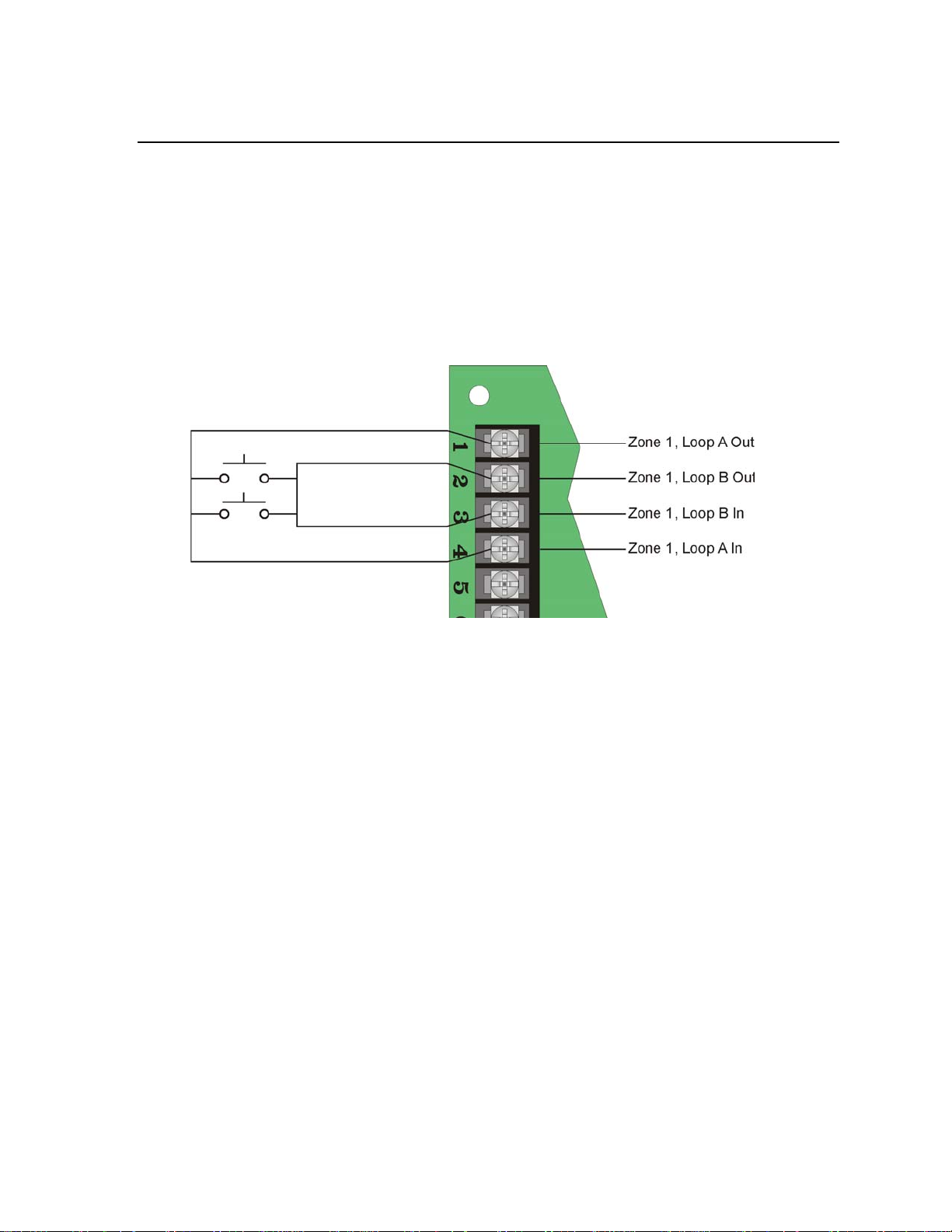
3.10.1 Class A (Style D) Zones
Zones 1 is for a class A (style D) zone. It is intended for use with non-powered devices such as waterflow
switches. Do NOT use smoke or duct detectors on Class A zones.
Each class A zone is a four-wire circuit that allows an alarm to be detected even after a single open or ground
fault occurs. When a single open or ground fault occurs, the audible trouble signal will sound and the 5104 will
report the trouble to the central station.
Figure 3-6 shows how to wire a class A (style D) loop. No end-of-line (EOL) resistor is needed for this zone.
This zone must be wired using normally open contacts.
Figure 3-6 Class A (style D) Supervised Fire Loop
(Normally Open Sensors Only)
Note: Class A wiring is to be used for dry contacts only and does not support 2-wire detectors.
3-11
Page 20

Model 5104B Installation Manual 151053-L8
Model 7628
4.7 K EOL
3.10.2 Class B (Style B) Zones
Zones 2 through 6 are class B (style B) fire zones. Each class B zone consists of a two-wire circuit that will
detect the occurrence of an open in the loop, but may not be able to detect an alarm after such an occurrence. The
detection of an open will cause the audible trouble signal to sound and the 5104 will report the trouble to the cen-
tral station.
Figure 3-7 shows how to wire a class B (style B) loop. One side of each class B loop connects to a zone input ter-
minal and the other side of each loop connects to loop power. For each loop, use a 4.7K-ohm EOL resistor wired
in parallel with the normally open contact farthest from the panel.
Figure 3-7 Model 5104B Class B (Style B) Loops
Note: Does not support 2-wire detectors.
Maximum Loop Resistance - 50 ohms
Maximum Total alarm current for all class B (Style B) zones - 750 mA
Maximum Standby Current per Zone:
Output (loop power) 750 mA
Input 0.5 mA
Note: UL requires all wiring to be at least 18 gauge.
3-12
Page 21

Installation 151053-L8
Model 160150
Supervision
Module
Model 7628
EOL Resistor
ESL 449CT
3.10.3 Four-Wire Smoke Detector Connection
4-wire smoke detectors must use a power supervision module. Connect four-wire smoke detectors as shown in
Figure 3-8.
Figure 3-8 4-wire Smoke Detector Connections
3-13
Page 22

Model 5104B Installation Manual 151053-L8
Wheelock
Model MB-G10-12-R
12 VDC Bell
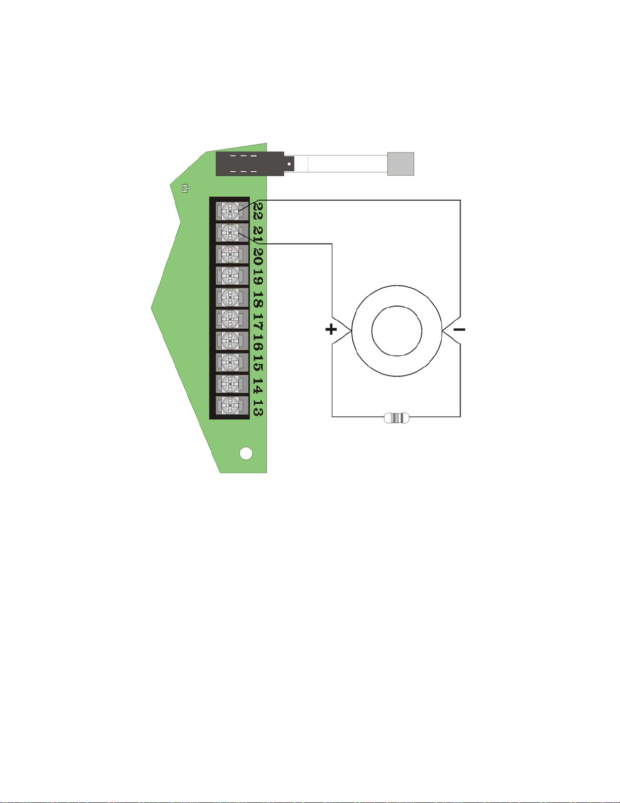
3.11 Supplemental Notification Appliance Installation
The Supplemental notification circuit supplies a DC output that can be used to power a DC audible device during
an alarm condition. Pressing the reset / silence switch will silence the output. Refer to section 6.2.7, Step 14, to
program the notification circuit’s supervision properties.
3.11.1 Non-Supervised Notification Appliance Wiring
Figure 3-9 illustrates how to wire a non-supervised notification device to the control panel.
Figure 3-9 Non-Supervised Alarm Bell Wiring
Note: Polarities shown in Figure 3-9 illustrate the polarity in an alarm condition. Under normal conditions the
polarity of terminals 21 and 22 are reversed.
Note: Per NFPA 72 Requirements the means of silencing a Supervisory Signal or Alarm must be located within
a locked cabinet. To comply, DO NOT install the reset/silence switch extruder or remove the switch knockout.
3-14
Page 23
Installation 151053-L8
Model 7628
4.7 K EOL
Wheelock
Model MB-G10-12-R
12 VDC Bell
3.11.2 Supervised Notification Appliance Wiring
When using a supervised notification device any open or shorted wiring condition will be reported as a trouble.
Figure 3-10 illustrates how to wire a supervised notification device to the control panel. Refer to Section 6.2.7
Step 14 to program the notification circuit’s supervision properties.
Figure 3-10 Supervised Alarm Bell Wiring
Note: Polarities shown in Figure 3-10 illustrate the polarity in an alarm condition. Under normal conditions the
polarity of terminals 21 and 22 are reversed.
3-15
Page 24

Model 5104B Installation Manual 151053-L8
To RJ31X
To RJ31X
3.12 Telephone Line Connections
The 5104 control panel connects to the phone lines with a 7860 cable, which plugs into an RJ31X phone jack.
The telephone company will install an RJ31X phone jack if you request them. Both telephone lines must be
installed to comply with NFPA 72. Wire the phone lines as shown in Figure 3-11.
Figure 3-11 Telephone Line Connections
3-16
Page 25

Installation 151053-L8
3.13 Model 5230 Installation
The optional 5230 remote annunciator provides both trouble and alarm annunciation, and a convenient means of
English-language programming the system.
Figure 3-12 Model 5230 Remote Annunciator.
3.13.1 Mounting the 5230
When installing the 5230 as a permanent component of the system it must be mounted to a dual gang electrical
box. All wire runs must use 12 to 18 AWG wire with a maximum length of 100 0 feet. The annunciator must be
supervised.
Follow these instruction to properly install the 5230 remote annunciator:
1. Remove the rear mounting plate:
By inserting a #4 flat blade screwdriver into the slot located on the bottom edge of the annunciator and gen-
tly turn the screwdriver until the mounting plate pulls away from the frame.
2. Secure the rear mounting plate to the dual gang electrical box.
Be sure to orientate the rear mounting plate so that the word “TOP” is toward the top of the plate and facing
3-17
Page 26

Model 5104B Installation Manual 151053-L8
Mounting Holes
Orientation Mark
Wire Access Hole
Restraining
Tabs
Restraining
Tabs
toward you. See Figure 3-13.
Figure 3-13 Rear Mounting Plate
3. Set the desired ID for the 5230 by setting the dip switches (on = up) as follows:
ID Number Dip Switch 1 Dip Switch 2 Dip Switch 3 Dip Switch 4
0* On On On On
1 Off On On On
2OnOffOnOn
3OffOffOnOn
*Not supervised
4. Pull wire through the wire access hole and connect the wires as follows:
130294
Quick Connect Cable
Brown 1 Annunciator Ground 23 Ground
Red 2 Annunciator Power 24 Accessory Power
Orange 3 Annunciator Input 25 Serial Data Out
Yellow 4 Annunciator Output 26 Serial Data In
Number Description Number Description
5230 Terminals 5104 Terminals
5. Snap the 5230 into place by lining up the 5230 onto the restraining tabs and snapping the 5230 into place.
Note: Refer to Section 5 for 5230 Operation.
3-18
Page 27

151053-L8
Section 4 Add-on Fire Communicator Application
The 5104 can be used to communicate the status of a larger or pre-e xisting (r efer red to as Ho st panel
in this manual) fire control system that does not have a digit al communicato r. To configure the 5104 as
an add-on communicator wire it as shown in Figure 4-1.
Figure 4-1 5104 Add-on Communicator Configuration Using 5104 Transformer for Power
Note: If power is supplied by the 5104 transformer, the host control panel must not send the 5104 a loss
of AC signal.
If power is supplied by the 5104 transformer, do not select the Add-on Dialer option in program-
ming.
Configure the zone inputs, phone lines and annunciator as shown in Section 3 of this manual.
4-1
Page 28

151053-L8
Supervisory
Condition Only
Alarm High
Priority Event
Indicates Other Event Have Occurred
Section 5 5230 Operation
This section contains information about the op eration of the 510 4 through a 523 0 remote annuncia tor.
5.1 5230 Display Messages
If the 5104 is not reporting, being program me d, and if no fu nc tion s ar e be in g en te re d, the LC D w ill
display the event of the highest priority. For example if a supervisory and an alarm condition has
occurred, the alarm condition will be displayed on the top line of the annunciator and any other low
priority events will be displayed on the lower line of the annunciator in abbreviated form. (See Figure 5-
1.)
Figure 5-1 Example of Displayed Messa ge s
Table 5-1 lists of the 5230 messages:
Table 5-1: 5230 LCD Messages and Meanings
Message Meaning
Trouble Zone # (1-6) Trouble condition exist on the zone or zones indicated by #
Alarm Zone # (1-6) Alarm condition exist on the zone or zones indicated by #
Low AC AC power has been lost.
Trouble Line 1 Trouble condition on phone line 1.
Trouble Line 2 Trouble condition on phone line 2.
Dialer Trouble Indicates a dialer failed condition.
Earth Ground Fault Indicates that an earth ground fault condition exists.
Earth Pwr Fault Indicates that an earth ground to power, fault condition exists.
Silenced A trouble condition exists and the annunciation has been turned off.
System Normal Displayed if no trouble, alarm or 5230 system error exists.
Data Lost Displayed if event memory overflows.
Reporting A report is being transmitted to central station.
Up/Download Data is being uploaded or downloaded from the central station computer.
Bus Trouble The 5230 cannot communicate with 5104.
Try Again If there is a 10 seconds time lapse between key presses while entering a function,
the 5230 will display this message. An invalid entry was made.
5-1
Page 29

Model 5104B Installation Manual 151053-L8
ENTER
7
ENTER
SET
9
TIME
ENTER
0
TEST
ENTER
CLEAR
DISABLE
SHIFT
SILENCE
STEP
Table 5-1: 5230 LCD Messages and Meanings
Message Meaning
Trouble Remote # (1-3) One or more 5230 annunciators are in trouble. The 5230 ID number is indicated
in the # place.
EEPROM Sum Error Error during program mode.
Low Battery Battery voltage is less than 10.2 VDC.
Trouble Smk Pwr Smoke loop power is less than 10 V or an overcurrent condition exists.
Bell Trouble Trouble condition on the notification circuit.
Trouble Com 1 Auto test or manual test unable to report on line 1.
Trouble Com 2 Auto test or manual test unable to report on line 2.
Supervisory # (1-6) Alarm condition on the zone programmed as the sprinkler zone.
5.2 5230 Touchpad Functions
There are several key functions used on the 5230 to input to the 5104, which are de scri bed in Table 5-
2. However, as the 5230 is used with other control panels, not all the key function apply to the 5104.
Table 5-2: Touchpad Keystrokes and Their Task or Function
T ask or Function Keystroke
Enter function or data.
Used initiate any command or to enter a step parameter
into programming memory.
Enter Program Mode.
Set Time.
Manual Test.
Sends a phone test to central station.
Clear.
Used to delete the most recent key sequence from
annunciator memory. Used to correct an incorrect entry.
Shift.
Used with other keys to enter alpha-numeric values.
This key is labeled Disable/Shift, but is only used as a
shift task.
Silence.
Used to silence audible trouble or alarm annunciations.
Note: Trouble or supervisory annunciations will be si-
lenced immediately when you press the silence key followed
by the installer or operator code. Silences notification output,
while 5230 remains audible.
. See examples below.
Installer Code.
Installer Or Operator Code.
Installer or Operator Code
followed by the time in military (24 hr clock).
Installer or Operator Code.
5-2
Page 30

5230 Operation 151053-L8
SILENCE
STEP
LOAD
4
ENTER
DISPLAY
6
TRBL.
ENTER
DISPLAY
5
MEMORY
ENTER
DIAL.
3
RESET
ENTER
Table 5-2: Touchpad Keystrokes and Their Task or Function
T ask or Function Keystroke
Step.
Used to advance to a different programming step while
in programming mode. In reference to any
programming tasks this key will be referred to as the
“Step” key.
Perform upload or download to a remote computer.
Display Troubles.
Used to display any system troubles.
Display Memory
Used to display all system events including Alarms,
Troubles, and Supervisory conditions.
Dialer Reset.
Resets dialer and discontinues communication
attempts.
Refer to Section 6 for programming information.
followed by the desired step number.
Installer Code.
Installer or Operator Code.
Installer or Operator Code.
Installer Code.
5-3
Page 31

151053-L8
Section 6 Programming
This section contains information pertaining to the programming of the 5104 with the 5230 Remote Annunciator.
All programming is stored in an EEPROM (Electrically Erasable Read-Only Memory) chip, which is nonvolatile memory storage. The various areas of programming are referred to as programming steps. These steps
are covered in greater detail in Section 6.2.5.
6.1 UL 864 Programming Requirements
NOTICE TO USERS, INST ALLERS, AUTHORITIES HAVING JURISDICTION, AND OTHER INVOLVED
PARTIES:
This product incorporates field programmable software. In order for the product to comply with the requirements in
the Standard for Control Units and Accessories for Fire Alarm Systems, UL 864, certain programming features or
options must be limited to specific values or not used at all as indicated below.
Programming Option
Low AC Hours Y 0 – 30 hours 1 – 3 hours
Test Interval Y 4, 6, 12, 24 hours 4, 6, 12, 24 hours
Format #1 & Format #2 Y 3-4, 6-7 0,2,5,8
Add-on Dialer N Y & N
Permitted in
UL 864 (Y/N)
Possible Settings
Settings Permitted in UL
864
6.2 5230 Programming
6.2.1 Default User Codes
The 5230 uses two programmable us er co des (Installer and Operator codes). This section will refer to these user
codes as either the Installer Code or the Operator Code. Table 6-1 lists the factory default Installer and Operator
codes:
Table 6-1: Factory Default User Codes
User Codes Factory Default
Installer Code 5104
Operator Code 1111
6.2.2 How to Enter and Exit Program Mode
This section describes how to enter and exit programming mode.
6.2.3 How to Enter Program Mode
Follow these steps to enter program mode:
6-1
Page 32

Model 5104B Installation Manual 151053-L8
SILENCE
STEP
SILENCE
STEP
CLEAR
CLEAR
Line 1
Step Nam e
Line 2
Programmed Value
DISABLE
SHIFT
DISABLE
SHIFT
LOAD
4
ENTER
1. Press 7.
2. Press ENTER.
3. Enter the Installer Code.
6.2.4 How to Exit Program Mode
To exit program mode press
6.2.5 Step Programming
All programming, for the 5104, done through the 5230 is done in steps. Each step programs a set parameter of the
5104, such as phone numbers, reporting formats, and zone function s.
6.2.6 Maneuvering in Program Mode
This section describes how to maneuver through programming more efficiently.
6.2.6.1 Entering Selected Values
When in program mode the two-line display shows the step name on the first line and the shows the present value
programmed for that step (see Figure 6-1).
Figure 6-1 Example of 5230 Display
To enter a new value into line 2, simple enter that value and press the enter key.
Yes or No Selections
When the selection choices are Yes or No, you can press any numbered key to toggle the selection between Yes
or No then press the enter key to program your choice into memory.
Selecting Alpha-numeric characters
To enter a number 0-9, simply press the key corresponding to the dig it(s) you desire. For example, to enter a
phone number of 123-4567 press the keys, in order, 1234567 then enter.
T o enter Alpha character (A-E) press the followed by digits 1 (for A), 2 (for B), 3 (for C), 4 (for D), 5
(for E). For example, to enter a 3/1 Alarm Code of D (see Table 6-3 for step information), press
to enter the D character.
6-2
Page 33

Programming 151053-L8
DISABLE
SHIFT
RESET
ALARM
1
DISABLE
SHIFT
CLEAR
MEMORY
2
DISABLE
SHIFT
DIAL.
RESET
3
DISABLE
SHIFT
LOAD
4
SILENCE
STEP
Special Character and Functions
Some phone number require special characters or functions to dial the central station correctly. Table 6-2 lists the
special character used for dialing a phone number and CIC (Carrier ID Code) codes.
Table 6-2: Special Characters for Dialing Sequence
Character Touchpad Inputs Displayed Character
Pause A
*B
#C
Look for second dial tone. D
6.2.6.2 Bypass a Step
To bypass a step to get to the next step, simply press the enter key without entering any data.
6.2.6.3 Go to a Step
You may desire to program only a few features and do not wish to step through the entire programming menu. To
do this follow the steps below.
1. Press .
2. Enter the step number you wish to go to.
3. Press ENTER.
6.2.7 Programming Steps
Table 6-3 lists all the steps names, their task, the choices available in those steps, and the factory default setting
of those steps.
Table 6-3: List of Programming Steps
Step # Task Choices Default
Sets the 3/1 reporting format code sent for an
Step 0 3/1 Alarm Code 0 - 9, A, B, C, D, E 1
Step 1 3/1 Sprnk Code 0 - 9, A, B, C, D, E 2
Step 2 3/1 Trouble Code 0 - 9, A, B, C, D, E 8
Step 3 3/1 Restore Code 0 - 9, A, B, C, D, E 7
"Fire Alarm". Use the Shift key plus digits 1 - 5
for letters A - E.
Sets the 3/1 reporting format code sent for a
"Sprinkler Supervisory". Use the Shift key plus
digits 1 - 5 for letters A - E.
Sets the 3/1 reporting format code sent for a
"Trouble". Use the Shift key plus digits 1 - 5 for
letters A - E.
Sets the 3/1 reporting format code sent for a
"Restore". Use the Shift key plus digits 1 - 5 for
letters A - E.
6-3
Page 34

Model 5104B Installation Manual 151053-L8
Table 6-3: List of Programming Steps
Step # Task Choices Default
Sets the 3/1 reporting format code sent for a
Step 4 3/1 Test Code 0 - 9, A, B, C, D, E 9
Step 5 Low AC Hours 0 - 30 hrs* 3
Step 6 # Rings 0 - 15 0
Step 7 Line 1 DTMF Yes or No No
Step 8 Line 1 Prefix 1 to 8 digits None
Step 9 Line 2 DTMF Yes or No No
Step 10 Line 2 Prefix 1 to 8 digits No ne
Step 11 Must Report #1 Yes or No No
Step 12 Must Report #2 Yes or No No
"Test Code". Use the Shift key plus digits 1 - 5
for letters A - E.
Set the number of hours the control panel will
wait to report a loss of AC power to the central
station.
Used to set the number of rings before the
5104 will answer the phone line to perform a
download from a computer.
0 = disabled, which means the 5104 will not
answer an in coming call.
Yes = DTMF (Touch Tone) dialing enabled.
No = Rotary dialing enabled.
Press any number key to toggle the setting
between "Yes" or "No".
Enter 8 digits to phone line 1. Use special
characters to add pauses, #, *, and “look for
second dial tone” characters into the line 1
prefix number. See Table 6-2 for special
characters.
Yes = DTMF (Touch Tone) dialing enabled.
No = Rotary dialing enabled.
Press any number key to toggle the setting
between "Yes" or "No".
Enter 8 digits to phone line 2. Use special
characters to add pauses, #, *, and “look for
second dial tone” characters into the line 2
prefix number. See Table 6-2 for special
characters.
Set phone number dialing priority. When the
5104 sends a report, it attempts to send the
report to the priority phone number (see steps
16 - 19). If the priority phone number is not
available, the system tries the other phone
number. It continues to alternate between the
two phone numbers until the report is sent to
one of the phone numbers.
If phone #2 is the phone number available, the
report will go to #2. How ever, if the Must
Report #1 option has been selected, the
system will continue to try and send the report
to phone #1. Press any numeric-digit to toggle
the selection from Yes to No.
See also step 1 1. If phone #1 is the first phone
number available, the report will go to phone
#1. However, if the Must Report #2 option is
selected, the system will continue trying to
report to phone #2 until it succeeds or
exhausts the programmed number of attempts.
6-4
Page 35

Programming 151053-L8
Table 6-3: List of Programming Steps
Step # Task Choices Default
Press any numeric-digit to toggle the selection
from Yes to No.
Step 13 Re lay Alarm Yes or No No
Step 14 Re lay Supervise Yes or No No
Step 15 # of 5230 0 - 3 0
Step 16 Send Alarm #1 Yes or No Yes
Step 17 Se nd Trouble #1 Yes or No Yes
Step 18 Send Test #1 Yes or No Yes
Step 19 Report Sprnk #1 Yes or No Yes
Step 20 Report Sprnk #2 Yes or No No
Yes = Bell circuit activates during alarm
condition by the auxiliary relay.
No = Bell circuit activates during a dialer failed
condition.
Press any numeric-digit to toggle the selection
from Yes to No.
Yes = Bell circuit is supervised (see Figure 3-
10).
No = Bell circuit in unsupervised (see Figure 3-
9).
Sets the number of annunciators that will be
supervised.
0 = no supervision on any of the system
annunciators.
Set priority for alarm reports. Press any
numeric-digit to toggle the selection from Yes
to No.
Yes = Priority phone number is #1.
No = Priority phone number is #2.
Set priority for trouble reports.
Yes = Priority phone number is #1.
No = Priority phone number is #2.
Set priority for manual and auto test reports.
Yes = Priority phone number is #1.
No = Priority phone number is #2.
Set how zone 1 will report. Press any numericdigit to toggle the selection from Yes to No.
Y e s = If you want to report troubles and alarms
as a sprinkler (Supervisory), when using SIA
format.
No = If you want troubles and alarms to report
as fires (Alarm).
Note: Bells will only sound if "No" is select-
ed.
Set how zone 2 will report. Press any numericdigit to toggle the selection from Yes to No.
Y e s = If you want to report troubles and alarms
as a sprinkler (Supervisory), when using SIA
format.
No = If you want troubles and alarms to report
as fires (Alarm).
Note: Bells will only sound if “No” is select-
ed.
6-5
Page 36

Model 5104B Installation Manual 151053-L8
Table 6-3: List of Programming Steps
Step # Task Choices Default
Set how zone 3 will report. Press any numericdigit to toggle the selection from Yes to No.
Y e s = If you want to report troubles and alarms
as a sprinkler (Supervisory), when using SIA
Step 21 Report Sprnk #3 Yes or No No
Step 22 Report Sprnk #4 Yes or No No
Step 23 Report Sprnk #5 Yes or No No
Step 24 Report Sprnk #6 Yes or No No
Step 25 Latch Sprnk Yes or No No
format.
No = If you want troubles and alarms to report
as fires (Alarm).
Note: Bells will only sound if “No” is select-
ed.
Set how zone 4 will report. Press any numericdigit to toggle the selection from Yes to No.
Y e s = If you want to report troubles and alarms
as a sprinkler (Supervisory), when using SIA
format.
No = If you want troubles and alarms to report
as fires (Alarm).
Note: Bells will only sound if “No” is select-
ed.
Set how zone 5 will report. Press any numericdigit to toggle the selection from Yes to No.
Y e s = If you want to report troubles and alarms
as a sprinkler (Supervisory), when using SIA
format.
No = If you want troubles and alarms to report
as fires (Alarm).
Note: Bells will only sound if “No” is select-
ed.
Set how zone 6 will report. Press any numericdigit to toggle the selection from Yes to No.
Y e s = If you want to report troubles and alarms
as a sprinkler (Supervisory), when using SIA
format.
No = If you want troubles and alarms to report
as fires (Alarm).
Note: Bells will only sound if “No” is select-
ed.
Set how the sprinkler zone will operate. Press
any numeric-digit to toggle the selection from
Yes to No.
Yes = When the sprinkler zone shorts for a
duration longer than the Zone Response (set in
steps 39 through 44), the annunciator remains
active until reported or manually silenced.
No = When the sprinkler zone shorts for a
duration longer than the Zone Response (set in
steps 39 through 44), the zone will follow
system status and indicate a supervisory on
that zone for the duration of the faulted
condition.
6-6
Page 37

Programming 151053-L8
Table 6-3: List of Programming Steps
Step # Task Choices Default
Enter six-digits for an account number. For
accounts shorter than 6-digits use leading
Step 26 Account #1 6-digits 105104
Step 27 Attempts #1 3 - 5 3
0 = SIA8
1 = Reserved
2 = SK4/2
3 = BFSK14 *
Step 28 Format #1
Step 29 CIC #1 1 to 8 digits None
Step 30 Phone #1 1 to 16 digits None
Step 31 Account #2 6-digits 205104
Step 32 Attempts #2 3 - 5 3
Step 33 Format #2 SK4/2 See Step 28.
Step 34 CIC #2 None See Step 29.
Step 35 Ph one #2 None See Step 30.
Step 36 Computer Account 6-digits 305104
4 = BFSK23*
5 = SIA20
6 = 3/1 14*
7 = 3/1 23*
8 = Contact ID
SIA8
zeros before you enter account number, so
that all six places are filled. For example, if the
format requires a shorter account number,
such as 3/1 enter 000123.
Select the number of attempts the dialer will
make to report to this account before a dialer
failed condition occurs. the dialer will then call
the other account. A total of 15 attempts will be
made.
Selects the reporting format to be used on
phone number 1. Enter the number of the
choice (see choice column) to select the
desired reporting format. See Section 7 for
detailed information on the 5104 reporting
formats.
* for these choices, See Table 6-1
Carrier Identification Code is the prefix that
needs to be dialed before a phone number to
access a particular long distance carrier. Use
special characters to add pauses, #, *, and
“look for second dial tone” characters into the
phone number. See Table 6-2 for special
characters.
Enter 16 digits for phone number 1. Use
special characters to add pauses, #, *, and
“look for second dial tone” characters into the
phone number. See Table 6-2 for special
characters.
Enter up to six-digits for an account number.
For accounts shorter than 6-digits use leading
zeros before you enter account number, so
that all six places are filled. For example, if the
format requires a shorter account number,
such as 3/1 enter 000123.
Select the number of attempts the dialer will
make to report to this account before a dialer
failed condition occurs. the dialer will then call
the other account. A total of 15 attempts will be
made.
Account number used when reporting to the
downloading computer. If account number is
shorter than 6-digits use leading zeros.
6-7
Page 38

Model 5104B Installation Manual 151053-L8
Table 6-3: List of Programming Steps
Step # Task Choices Default
Carrier Identification Code is the prefix that
needs to be dialed before a phone number to
access a particular long distance carrier. Use
Step 37 Computer CIC 1 to 8-digits None
Step 38 Co mputer Phone 1 to 16-digits None
0 = 0.3 to 0.4 sec.
Step 39 Zone Response #1
Step 40 Zone Response #2 1
Step 41 Zone Response #3 1
Step 42 Zone Response #4 1
Step 43 Zone Response #5 1
Step 44 Zone Response #6 1
Step 45 Installers Code 4-d igits 5104
Step 46 Operato rs Cod e 4-digits 1111
Step 47 Test Time
Step 48 Test Interval 0-3 3
1 = 3 to 4 sec.
2 = 16 to 20 sec.
3 = 32 to 40 sec.
24-hrs military
time
1
01:30
special characters to add pauses, #, *, and
“look for second dial tone” characters into the
phone number. See Table 6-2 for special
characters.
Enter up to 16 digits for phone number 1. Use
special characters to add pauses, #, *, and
“look for second dial tone” characters into the
phone number. See Table 6-2 for special
characters.
Select the speed that this zone will respond to
alarm, trouble, or restore conditions. Selection
0 is not recommended, as it may cause
unnecessary alarm. Selection 2 & 3 are
considered delayed response. Delayed
responses may be used only on waterflow
switches, unless the waterflow switch has a
built-in delay. Any selection other than 0 - 3 will
scroll through the available selections.
See Step 39
Enter a 4-digit code to be used by the installer
or service technician.
The installer code allows the user to initiate
downloads, set time, and entering program
mode.
Enter a 4-digit code to be used by the operator.
The operator code allows the user to silence
annunciations and to conduct manual tests.
Enter the time that a automatic test will be sent
to central station. Use a 24-hour military time
format. For example, to enter the time 5:15 pm
enter 17:15. Use leading zeros for single-digit
hours, such as 01:30 etc.
Note: Any events that have not been re-
stored will be sent along with the test report.
Enter how often the control panel will do an
automatic phone test, keyed off the Test Time.
Selections 0-3 respectively; every 4 hours, 6
hours, 12 hours or 24 hours.
6-8
Page 39

Programming 151053-L8
Table 6-3: List of Programming Steps
Step # Task Choices Default
Press any numeric-digit to toggle the selection
from Yes to No.
Yes = If the 5104 is used as an add-on
communicator for a host panel. This tells the
Step 49 Ad d-on Dialer Yes or No No
* For UL certified systems Low AC Hours in Step 5 must be set from 1 - 3 hours.
5104 not to test the battery or earth ground,
which could cause interference with the host
panel.
No = The 5104 will test battery and earth
ground.
see Table 6-1
6-9
Page 40

151053-L8
Section 7 Reporting
The 5104 can transmit information in 5 different formats. This section describes the five basic reporting formats
of the 5104 and the codes that they send to a central station receiver. Of these 5 formats some of the formats offer
a more specific selection for that format. For example, you can select a 3/1 format that requires a 1400 or 2300
Hz handshake, or SIA format that can handle 8 of 20 events per call. Selecting the correct format depends on the
type of receiver that will receive calls from the 5104.
7.1 Reporting Formats
This section gives a description of each of the 5104 reporting formats. Refer to Table 7-1.
Table 7-1: Reporting Formats Descriptions
Format Name
Category
Name
Programming
Name
Description
3/1 3/1 14 Old format, transmits a 3-digit account number and a 1-digit alarm
code. Transmissions are acknowledged at 1400 Hz. See Table 6-1
3/1 23 Old format, transmits a 3-digit account number and a 1-digit alarm
code. Transmissions are acknowledged at 2300 Hz. See Table 6-1
4/2 SK 4/2 Tone burst format, transmits a 4-digit account code and 2-digit alarm
code. Transmissions are acknowledged at 1400 Hz.
BFSK BFSK14 Radionics format which transmits a high-speed, single-round, 3-digit
account number, followed by report information. Transmissions are
acknowledged at 1400 Hz. See Table 6-1
BFSK23 Radionics format which transmits a high-speed, single-round, 3-digit
account number, followed by report information. Transmissions are
acknowledged at 2300 Hz See Table 6-1.
SIA SIA8 Security Industry Association standard communication format which
send a maximum of 8 events per call.
SIA20 Security Industry Association standard communication format which
send a maximum of 20 events per call. Up to a 6-digit account
number.
Contact ID Contact ID Ademco Contact ID format. DTMF (Dual Tone Multiple Frequency)
format. Send a 4-digit account number. Transmission are
acknowledged at both 1400 and 2300 Hz.
7-1
Page 41

Model 5104B Installation Manual 151053-L8
7.2 Reporting Codes
Table 7-2 list the events sent by the 5104 and the code that is sent for that event by the type of reporting format
used.
Table 7-2: Event and Reporting Code by Format
Event
Fire Alarm 1-6 FA1 -
Fire Alarm Restore 1-6 FH1 -
Fire Trouble 1-6 FT1 -
Fire Trouble Restore 1-6 FJ1 - FJ6 71 - 76 Restore Code E1 - E6 3 373 001 - 3
Sprinkler Supervisory 1-6 SS1 -
Sprinkler Supervisory Restore 1-6 SR1 -
Sprinkler Trouble 1-6 ST1 -
Sprinkler Trouble Restore 1-6 SJ1 - SJ6 71 - 76 Restore Code E1 - E6 3 203 001 - 3
Annunciator Trouble 1-3 ET1 -
Annunciator Restore 1-3 ER1 -
SIA8 &
20
FA6
FH6
FT6
SS6
SR6
ST6
ET3
ER3
SK4/2 3/1 1400 &2300 BFSK14 & 23 Contact ID
01 - 06 Alarm Code 01 - 06 1 110 001 - 1
110 006
21 - 26 Restore Code E1 - E6 3 110 001 - 3
110 006
61 - 66 Trouble Code F1 - F6 1 373 001 - 1
373 006
373 006
01 -06 Sprinkler Code 01 - 06 1 203 001 - 1
203 006
21 - 26 Restore Code E1 - E6 3 203 001 - 3
203 006
61 - 66 Trouble Code F1 - F6 1 203 001 - 1
203 006
203 006
33 Trouble Code FD 1 330 001 - 1
330 003
37 Restore Code ED 3 330 001 - 3
330 003
Bell Trouble ET32 33 Trouble Code FD 1 320 001
Bell Restore ER32 37 Restore Code ED 3 320 001
Earth Ground Trouble ET38 33 Trouble Code FD 1 310 000
Earth Ground Restore ER38 37 Restore Code ED 3 310 000
Earth Power Trouble ET39 33 Trouble Code FD 1 310 000
Earth Power Restore ER39 37 Restore Code ED 3 310 000
Smoke (Loop) Power Trouble ET40 33 Trouble Code FD 1 300 000
Smoke (Loop) Power Restore ER40 37 Restore Code ED 3 300 000
Aux Power Trouble ET43 33 Trouble Code FD 1 300 003
Aux Power Restore ER43 37 Restore Code ED 3 300 003
AC Trouble AT0 60 Trouble Code FA 1 301 000
AC Restore AR0 70 Restore Code EA 3 301 000
Battery Trouble YT0 69 Trouble Code F9 1 302 000
Battery Restore YR0 79 Restore Code E9 3 302 000
7-2
Page 42

Reporting 151053-L8
Table 7-2: Event and Reporting Code by Format
Event
Trouble Phone Line #1 LT1 31 Trouble Code FB 1 351 000
Restore Phone Line #1 LR1 35 Restore Code EB 3 351 000
Trouble Phone Line #2 LT2 32 Trouble Code FC 1 352 000
Restore Phone Line #2 LR2 36 Restore Code EC 3 352 000
Communications Failure Line #1 YC1 31 Trouble Code FB 1 351 000
Communications Restore Line #1 YK1 35 Restore Code EB 3 351 000
Communications Failure Line #2 YC2 32 Trouble Code FC 1 352 000
Communications Restore Line #2 YK2 36 Restore Code EC 3 352 000
Manual Test RX0 30 Test Code EE 1 601 000
Automatic Test (Normal) RP0 30 Test Code EE 1 602 000
Automatic Test (Abnormal) RY0 Test 9 Test Code EE 1 608 000
Downloading Passed RS0 30 Test Code EF 1 412 000
Downloading Failed RU0 30 Test Code FF 1 413 000
Data Lost RT0 39 Trouble Code FE 1 354 000
SIA8 &
20
SK4/2 3/1 1400 &2300 BFSK14 & 23 Contact ID
7-3
Page 43

Section 8 Troubleshooting
This section contains trouble shooting information for servicing the 5104. The following is a list of LED
indications, 5230 LCD messages, and their meaning. Along with this information are possible causes of these
problems and some solution.
151053-L8
LED
Indications
L3 Off Low AC AC power has been lost. Check for power on the primary of
L6 On Trouble Line 1 Trouble condition on line 1. Phone line or phone connections are
L7 On Trouble Line 2 Trouble condition on line 2.
L5 On Dialer Trouble Indicates a dialer failed condition.
L4 On. Silenced A trouble condition exists and the
L2 On Trouble Smk Pwr Smoke loop power is less than 10 V
5230 LCD Messages Meaning Cause and Correction
Trouble Zone #
(1-6)
Alarm Zone #
(1-6)
Earth Ground Fault Indicates that an earth ground fault
Earth Pwr Fault Indicates that an earth power fault
Data Lost Displayed if event memory
Bus Trouble The 5230 cannot communicate with
Try Again If there is a 10 seconds time lapse
Trouble Remote # One or more 5230 annunciator is in
EEPROM Sum Error Error during program mode. Exit program mode (see Section
Trouble condition exist on the zone
or zones indicated by #
Alarm condition exist on the zone or
zones indicated by #
condition exists.
condition exists.
annunciator has been turned off.
overflows.
5104.
between key presses while entering
a function, the 5230 will display this
message.
trouble. The 5230 ID number is
indicated in the # place.
or an overcurrent condition exists.
Overcurrent draw on terminal 6, 9, or
11.
The device connected to this zone is
in trouble. EOL problem on this loop.
This indication will clear once the
problem has been corrected
The device connected to this zone is
in the alarm condition.
the transformer.
bad or unable to report to central
station. Verify the programmed
central station phone number.
EOL problem on this loop. This
indication will clear once the problem
has been corrected
You waited to long between
touchpad entries and the system
timed out or an incorrect entry was
made.
Check for shorts or opens in wire
runs. Check to make sure that none
of the 5230 have the same ID code.
6.2.4) then re-enter program mode
and try again.
8-1
Page 44

Model 5104B Installation Manual 151053-L8
LED
Indications
L6 Flashes Trouble Com 1 Event reports, auto test or manual
L7 Flashes Trouble Com 2 Event reports, auto test or manual
L1 On Blank +12 Accessory power fault Check for over current on terminal
5230 LCD Messages Meaning Cause and Correction
Bell Trouble Trouble condition on the notification
circuit.
test unable to report on line 1.
test unable to report on line 2.
Supervisory # (1-6) Alarm condition on the zone
programmed as the sprinkler zone.
Low Battery Backup battery voltage is below 10.2
VDC.
Over current draw on the notification
circuit. Missing or incorrect EOL on a
supervised notification circuit.
Phone line voltage is O.K. but the
panel was unable to communicate on
line 1. Try dialing the phone number
that you programmed, from a
premise phone, to verify it is reaching
the central station. If that checks out
O.K. verify that you are using a
compatible reporting format with that
receiver.
Phone line voltage is O.K. but the
panel was unable to communicate on
line 2. Try dialing the phone number
that you programmed, from a
premise phone, to verify it is reaching
the central station. If that checks out
O.K. verify that you are using a
compatible reporting format with that
receiver.
Short on the programmed sprinkler
zone.
Check backup battery connection.
Check backup battery voltage level
with volt meter. Replace the backup
battery.
24.
8-2
Page 45

Silent Knight Fire Product Warranty and Return Policy
General Terms and Conditions
• All new fire products manufactured by Silent Knight have a limited warranty period of 36 months from the
date of manufacture against defects in materials and workmanship. See limited warranty statement for
details.
• This limited warranty does not apply to those products that are damaged due to misuse, abuse, negligence,
exposure to adverse environmental conditions, or have been modified in any manner whatsoever.
Repair and RMA Procedure
• All products that are returned to Silent Knight for credit or repair require a RMA (Return Authorization)
number. Call Silent Knight Customer Service at
800-328-0103 or 203-484-7161 between 8:00 A.M. and 5:00 P.M. EST, Monday through Friday to obtain a
return authorization number.
• Silent Knight T echnical Support is available at 800-446-6444 between 8:00 A.M. and 5:00 P.M. CST,
Monday through Friday.
• All returns for credit are subject to inspection and testing at the factory before actual determination is made
to allow credit.
• RMA number must be prominently displayed on the outside of the shipping box. See return address example
under Advanced Replacement Policy.
• Included with each return should be: a packing slip that has the RMA number, a content list, and a detailed
description of the problem.
• All products returned to Silent Knight must be sent freight pre-paid. After product is processed, Silent
Knight will pay for shipping product back to customer via UPS ground.
• Return the Silent Knight product circuit board only. Products that are returned in cabinets will be charged an
additional $50 to cover the extra shipping and handling costs over board only returns. Do not return
batteries. Silent Knight has the authority to determine if a product is repairable. Products that are deemed
un-repairable will be returned to the customer.
• Product that is returned that has a board date code more than 36 months from date of manufacture will be
repaired and the customer will be assessed the standard Silent Knight repair charge for that model.
Advanced Replacement Policy
• Silent Knight offers an option of advance replacement for fire product printed circuit boards that fail during
the first 6 months of the warranty period. These items must be returned with transportation charges prepaid
and must be accompanied by a return authorization.
• For advance replacement of a defective board, contact your local Silent Knight distributor or call Silent
Knight at 800-328-0103 to obtain a RMA (Return Authorization) number and request advanced
replacement.
• A new or refurbished board will be shipped to the customer. The customer will initially be billed for the
replacement board but a credit will be issued after the repairable board is received at Silent Knight. All
returned products must comply with the guidelines described under “General Terms and Conditions” and
“Repair and RMA Procedure”.
• The defective board must be returned within 30 days of shipment of replacement board for customer to
receive credit. No credit will be issued if the returned board was damaged due to misuse or abuse.
• Repairs and returns should be sent to:
Silent Knight / Honeywell
Attn: Repair Department / RA Number_______________________
12 Clintonville Road
Northford, CT 06472 USA
1
Page 46

Manufacturer Warranties and Limitation of Liability
Manufacturer Warranties. Subject to the limitations set forth herein, Manufacturer warrants that the Products
manufactured by it in its Northford, Connecticut facility and sold by it to its authorized Distributors shall be free,
under normal use and service, from defects in material and workmanship for a period of thirty six months (36)
months from the date of manufacture (effective Jan. 1, 2009). The Products manufactured and sold by
Manufacturer are date stamped at the time of production. Manufacturer does not warrant Products that are not
manufactured by it in its Northford, Connecticut facility but assigns to its Distributor, to extent possible, any
warranty offered by the manufacturer of such product. This warranty shall be void if a Product is altered, service
repaired by anyone other than Manufacturer or its authorized Distributors. This warranty shall also be void if
there is a failure to maintain the Products and the systems in which they operate in proper working conditions.
MANUFACTURER MAKES NO FURTHER WARRANTIES, AND DISCLAIMS ANY AND ALL OTHER
WARRANTIES, EITHER EXPRESSED OR IMPLIED, WITH RESPECT TO THE
PRODUCTS,TRADEMARKS, PROGRAMS AND SERVICES RENDERED BY MANUFACTURER
INCLUDING WITHOUT LIMITATION, INFRINGEMENT, TITLE, MERCHANTABILITY, OR FITNESS
FOR ANY P AR TICULAR PURPOSE. MANUFACTURER SHALL NOT BE LIABLE FOR ANY PERSONAL
INJURY OR DEATH WHICH MAY ARISE IN THE COURSE OF, OR AS A RESULT OF, PERSONAL,
COMMERCIAL OR INDUSTRIAL USES OF ITS PRODUCTS.
This document constitutes the only warranty made by Manufacturer with respect to its products and replaces all
previous warranties and is the only warranty made by Manufacturer. No increase or alteration, written or verbal,
of the obligation of this warranty is authorized. Manufacturer does not represent that its products will prevent any
loss by fire or otherwise.
Warranty Claims. Manufacturer shall replace or repair, at Manufacturer's discretion, each part returned by its
authorized Distributor and acknowledged by Manufacturer to be defective, provided that such part shall have
been returned to Manufacturer with all charges prepaid and the authorized Distributor has completed
Manufacturer's Return Material Authorization form. The replacement part shall come from Manufacturer's stock
and may be new or refurbished. THE FOREGOING IS DISTRIBUTOR'S SOLE AND EXCLUSIVE REMEDY
IN THE EVENT OF A WARRANTY CLAIM.
Warn-HL-08-2009.fm
2
Page 47

Page 48

Silent Knight
12 Clintonville Road
Northford, CT 06472-1610
203-484-7161
Fax: 203-484-7118
www.silentknight.com
 Loading...