

Page 1
SD505-ADHR Duct Detector Housing
With Relay Module & SD505-DTS
Installation Instructions
The following are instructions on how to install
the SD505-ADHR & SD505-DTS to a Silent
Knight Addressable control panel.
SD505-ADHR Installation
The SD505-ADHR is a duct detector housing
with a built-in relay module that is used to
control a fan motor to stop air flow in a fire
alarm situation.
Specifications
Specification Parameter Rating
Alarm Relay Contact Rating: 10 A @ 120/240 VAC
Trouble Relay Contact Rat-
ing:
Operating Volt-
age:
Aux. Input Power
Current:
SLC Current for
Battery Calculations
Max. SLC Loop Resistance: 50Ω
Operating Temperature: 32° to 120° F (0° to 49° C)
Humidity: 10-85% RH
Air Velocity: 500-4000 fpm 300-4000
Sensitivity: 0.85 to 1.15%
SLC
Loop:
Aux. Pwr.
Input:
24 VDC Standby: 35 mA
24 VAC Standby: 50 mA
120 VAC Standby: 10 mA
240 VAC Standby: 5 mA
Alarm: .018 mA
Standby: .018 mA
2.5 A @ 30VDC
32 VDC
120/240 VAC, 24 VDC/VAC
Alarm: 75 mA
Alarm: 90 mA
Alarm: 20 mA
Alarm: 10 mA
SD505-APS SD505-AIS
fpm
0.5 to 0.81%
per foot
per foot
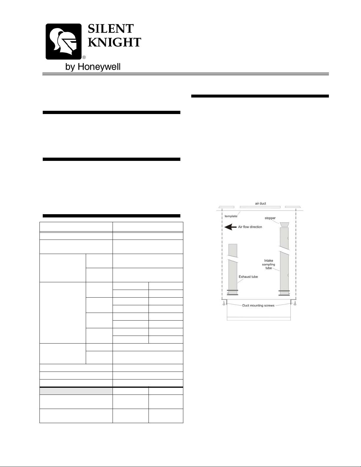
Mounting Instructions
Follow these steps to mount the SD505-ADHR:
1. Remove paper backing from mounting
template (packaged in installation kit) and
affix to duct at installation location.
2. Using the template as a guide, drill the four
mounting holes (3/32” diameter) for duct
detector mounting screws provided (4 # 12 x
1/2” sheet metal screws).
3. Use template as guide to drill or punch holes
for the sampling tubes in the air ducts (13/8” diameter).
4. Clean all holes.
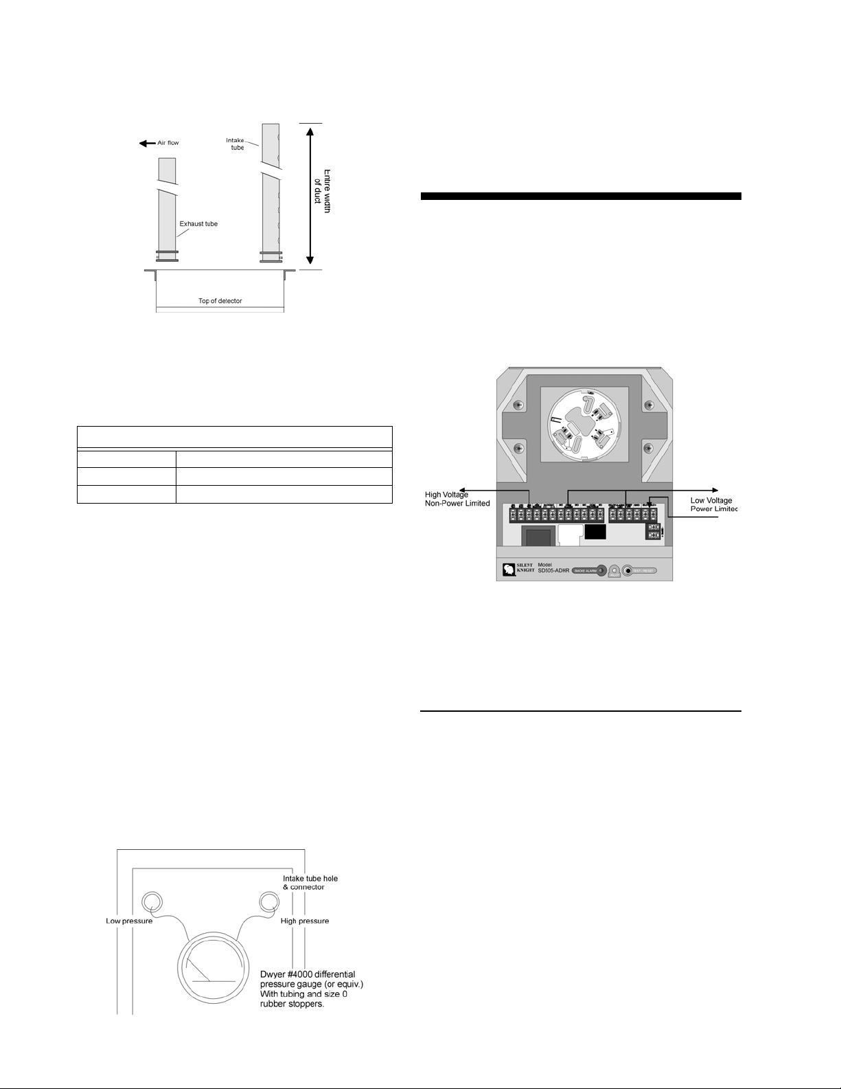
Sampling Tube Assembly
The sampling tubes can be ordered in standard
lengths and cut per requirements. See chart
below for available standard sizes. The intake
sampling tube is a piece of steel piping with a
series of holes drilled the entire length of the
tube. The tube should be cut to a size that allows
it to extend the entire width of the duct.
The holes must be facing into the air flow (see
Figure 1). The exhaust tube is a piece of steel
piping measuring 7 inches.
P/N 151126
Page 2
SD505-ADHR Duct Detector Housing With Relay Module & SD505-DTS Installation Instructions
The pressure differential between the input
sampling tube and exhaust tube should be
greater than 0.01” and less than 1.2” of water.
Wiring Instructions
This section contains information on how to
connect the SD505-ADHR to a power source, to
a fan motor, and to a SD505-DTS remote test
station. Wiring must conform to applicable local
codes, ordinances, and regulations covering this
Figure 1: Sampling Tube Orientation
5. Cut intake sampling tube to the desired
length.
6. Firmly insert the provided stopper into the
end of the intake sampling tube.
Standard Lengths for Intake Sampling Tubes
STS-2.5 For duct widths of 1.0’ to 2.5’
STS-5.0 For duct widths of 2.5’ to 5.0’
STS-10.0 For duct widths of 5.0’ to 10.0’
type of device. Refer to NFPA 90A and NFPA
72E for additional information on duct smoke
detector operation and installation.
7. Mount the detector by placing the
detector/sampling tube assembly into
position and secure to duct housing using
mounting screws.
Verify Air Flow and Direction
8. Verify that air velocity is appropriate for the
type of smoke detector you are using by
checking specifications of installation and, if
necessary, by using air velocity meter (Alnor
Model 6,000P or equivalent). See Figure 1.
Air Sampling Verification
9. Verify proper air sampling by using a
differential pressure gauge (Dwyer Model
4000 or equivalent). See Figure 2 for
connections.
Figure 3: Wire Routing Example
Important! 1/4" spacing must be maintained between
High and Low voltage circuits; as well as
between power limited and non-power
limited circuits.
Power Connections
The SD505-ADHR can be powered from a 120
VAC, 240 VAC, or 24 VDC/VAC power source.
Note: Only one power source can be used to power the SD505-
ADHR.
Figure 4 illustrates how to connect the various
types of power sources to the SD505-ADHR.
2 P/N 151126
Figure 2: Air Sampling Verification
Page 3

SD505-ADHR Duct Detector Housing With Relay Module & SD505-DTS Installation Instructions
FACP
Supervised
Power Limited
SD505-ADHR
Figure 4: Power Source Connections
FACP Connections
Follow these steps to properly connect the
SD505-ADHR to the FACP:
1. Turn power off and leave the detector head
off.
2. Wire the SD505-ADHR as show in Figure 5
or Figure 6.
FACP
Supervised
Power Limited
Figure 6: Class A (Style 6)
Alarm Relay
The Alarm relay can be used to shut off a fan
motor of a HVAC system to prevent the transfer
of smoke. See Figure 7.
Figure 7: Fan Motor Shut-off Block Diagram
Trouble Relay
SD505-ADHR
Figure 5: Class B (Style 4)
P/N 151126 3
The trouble relay is a form C relay that activates
if the input power is lost.
Page 4

SD505-ADHR Duct Detector Housing With Relay Module & SD505-DTS Installation Instructions
SD505-DTS Installation
The SD505-DTS is an optional remote test
switch station that connects to the SD505ADHR. The SD505-DTS also provides visual
access to the SD505-ADHR in installations
where the SD505-ADHR cannot physically be
seen.
SD505-DTS Wiring
Wire the SD505-DTS to the SD505-ADHR as
shown in Figure 8.
Figure 9: SD505-DTS Mounting and Assembly
Supervised
Power Limited
Figure 8: SD505-DTS Wiring Connections
Mounting The SD505-DTS
SD505-DTS Specifications
Parameter Rating
Current Draw Standby: 6 mA
Alarm: 6 mA
Dimensions (including red
trim plate):
Operating Temperature: 32° F to 120° F (0° C to 49° C)
Operating Voltage: 10 VDC
4-3/4” H x 3” W x 1-3/4” D
12.07 cm x 7.62 cm x 4.45 cm
The SD505-DTS mounts into a single gang
electrical switch box. See Figure 9.
4
Maple Grove, MN 55369-4927
763-493-6455 or 800-328-0103
© 2006 Silent Knight PN 151126 Rev C
7550 Meridian Circle
Fax: 763-493-6475
www.silentknight.com
 Loading...