

Page 1
I56-3546-000
SD500-SDM Installation
Instructions
The SD500-SDM two-wire smoke module
allows you to connect a loop of conventional
detectors to a Silent Knight addressable fire
alarm control panel (FACP). Each loop can then
be assigned an address on the FACP.
Specifications
Specification Parameter Rating
2-Wire Smoke Detector
Loop Current:
Operating Voltage: SLC 32 VDC
SLC Current for battery
calculation:
Operating Temperature: 32° - 120° F
Humidity: 10-85% RH
Max. SLC Loop Resistance: 50 Ω
Max. 2-wire Conventional Smoke Loop
Resistance
Dimensions: Length: 4-7/8”
For indoor use only
Compatibility
Standby: 2 mA max.
Alarm: 100 mA max.
Aux Power 24 VDC
Alarm: .55 mA
Standby: .55 mA
(0° - 49° C)
50 Ω
Width: 4-7/8”
Depth: 7/8”
Wiring
Note: Installation and wiring of this device must be done in
accordance with NFPA 72 and local ordinances.
Important! All wiring is supervised and power limited.
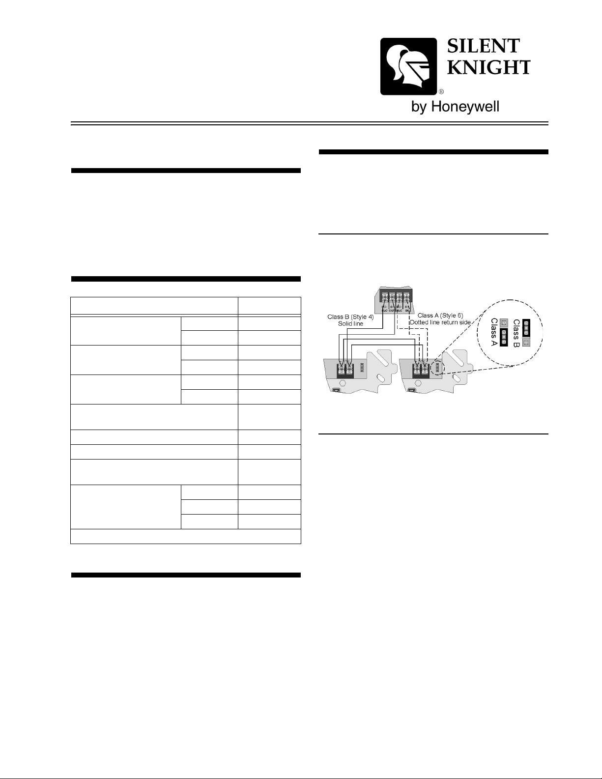
Connecting the SD500-SDM to the SLC Loop
The SD500-SDM connections to the 5815XL
internal and external are the same. Wire as
shown in Figure 1.
Figure 1: SLC Wiring
Smoke Detector Connections
This section contain instructions on how to
connect a 2-wire conventional smoke detector
loop to the SD500-SDM for either Class B (Style
B), or Class A (Style D).
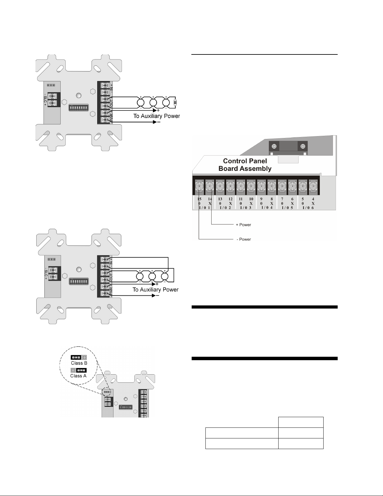
Class B (Style B) Wiring
Wire Class B (Style B) conventional smoke
detector loop to the SD500-SDM as shown in
Figure 2. Place the jumper block in the Class B
The SD500-SDM is compatible with all Silent
Knight addressable FACPs.
P/N 151193
Page 2
SD500-SDM Installation Instructions
(Style B) supervision position (see Figure 4).
Figure 2: Class B (Style B) 2-Wire Detector Loop
Note: Auxiliary power is supplied by a Regulated UL listed
power supply for Fire Protective Signalling Systems.
Class A (Style D) Wiring
Wire Class A (Style D) conventional smoke
detector loop to the SD500-SDM as shown in
Figure 3. Place the jumper block in the Class A
(Style D) supervision position (see Figure 4).
Flexput™ Circuits
The SD500-SDM can use aux power from any
24 VDC source. The following describes how to
use the Flexput circuits as the auxiliary power
source:
1. Connect the aux power wires to the Flexput
terminals using “X” terminals as positive
and “O” terminals as negative power. See
Figure 5.
Figure 3: Class A (Style D) 2-Wire Detector Loop
Figure 4: Supervision Selection Jumper
Auxiliary Power Using
Figure 5: Flexput Auxiliary Power Output
2. Configure the auxiliary power output for
constant output through programming. Refer
to the FACP installation manual form more
information.
For More Information
This document is for quick reference. For more
information, refer to the FACP installation
manual.
Two-Wire Smoke Detectors
Table 1 lists two-wire smoke detectors that are
compatible with the fire control panel. The table
is organized by manufacturer. The columns
show the number of detectors per loop that can
be used.
SD500-SDM
Identifier
Operating Voltage Range
24H
18.5–27.4 VDC
2 P/N 151193
Page 3

SD500-SDM Installation Instructions
Note: The maximum number of smoke detectors per zone is determined by both the current draw and the impedance of the smoke
detector. If too many smoke detectors are used on any zone, false alarms could occur.
Do not mix different models of detectors on any zone; false alarms could occur.
Do not mix detectors of different models unless the system is specifically intended to be installed in that configuration.
Control unit Smoke Reset T ime mu st be programmed for a number greater than or equal to the maximum r eset time of the smoke
detector.
T able 1: Compatible Two-Wire Smoke Detectors
Model Name or Number
Manufacturer
Apollo 55000-350 (45681-200) 55000-350 45681-200 24 / loop
ESL 429C (S10A) N/A S10A 30 / loop
(Base model name or
number in parentheses.)
55000-250 (45681-200) 55000-250 45681-200 24 / loop
55000-225 55000-225 45681-255, 256,
55000-226 55000-226 15/ loop
55000-227 55000-227 15 / loop
55000-325 55000-325 15 / loop
55000-328 5500-328 15 / loop
55000-326 55000-326 15 / loop
55000-327 55000-327 15 / loop
429CRT (S11A) N/A S11A 30 / loop
429CST (S11A) N/A S11A 30 / loop
429CT (S10A) N/A S10A 30 / loop
609U01-11 S10 S00 40 / loop
609U02-11 S10 S00/S03 40 / loop
611U (601U or 602U) S10 S00/S03 40 / loop
611UD (601U or 602U) S10 S00/S03 40 / loop
Compatibility ID
# per Loop
Head Base
15 / loop
45681-200, 220
230, 232, 251,
252
611UT (601U or 602U) S10 S00/S03 40 / loop
612U (601U or 602U) S10 S00/S03 40 / loop
612UD (601U or 602U) S10 S00/S03 40 / loop
71 1U (701E or 701U) N/A S10A 25 / loop
712U (701E or 701U) N/A S10A 25 / loop
713-5U (702E or 701U) N/A S10A 25 / loop
713-6U (702E or 701U) N/A S10A 25 / loop
721-U (S10A) N/A S10A 30 / loop
721-UT (S10A) N/A S10A 30 / loop
Falcon 525 FDT1 N/A 17 / loop
525T FDT1 N/A 17 / loop
P/N 151193 3
Page 4

SD500-SDM Installation Instructions
Table 1: Compatible Two-Wire Smoke Detect or s
Model Name or Number
Manufacturer
Hochiki SIH-24F (HS-224D OR
System Sensor 1400 A N/A 20 / loop
(Base model name or
number in parentheses.)
HD-3 HB-5 25 / loop
HSD-224)
SLK-24F (HS-224D) HD-3 HB-5 25 / loop
SLK-24FH (HS-224D) HD-3 HB-5 25 / loop
1451 (B401B) A A 20 / loop
2100 A N/A 20 / loop
2100T A N/A 20 / loop
2151 A N/A 16 / loop
2151T A N/A 16 / loop
2300T A N/A 20 / loop
2300 A N/A 20 / loop
2300TB A N/A 20 / loop
2400 A N/A 20 / loop
2400 (DH400) A N/A 20 / loop
2400AIT A N/A 20 / loop
Compatibility ID
# per Loop
Head Base
2400AT A N/A 20 / loop
2400TH A N/A 20 / loop
2451 (B401B) A N/A 20 / loop
2451DH (DH 400) A N/A 20 / loop
2451TH (B401B) A N/A 20 / loop
2W-B A N/A 20 / loop
2WT-B A N/A 20 / loop
2WTR-B A N/A 20 / loop
4 151193 Rev E
I56-3546-000
 Loading...