

Page 1

TAC Vista
TAC Pangaea
WorkStation
TAC Xenta 500/700/911/913
Product Manual
Page 2

Page 3

TAC Vista
TAC Xenta 500/700/911/913
Product Manual
Page 4

Copyright © 2011 Schneider Electric Buildings AB. All rights reserved.
This document, as well as the product it refers to, is only intended for licensed users. Schneider Electric Buildings AB owns the copyright of
this document and reserves the right to make changes, additions or deletions. Schneider Electric Buildings AB assumes no responsibility for
possible mistakes or errors that might appear in this document.
Do not use the product for other purposes than those indicated in this document.
Only licensed users of the product and the document are permitted to use the document or any information therein. Distribution, disclosure,
copying, storing or use of the product, the information or the illustrations in the document on the part of non-licensed users, in electronic or
mechanical form, as a recording or by other means, including photo copying or information storage and retrieval systems, without the express
written permission of Schneider Electric Buildings AB, will be regarded as a violation of copyright laws and is strictly prohibited.
Trademarks and registered trademarks are the property of their respective owners.
Page 5

TAC Xenta 500/700/911/913, Product Manual Contents
Contents
INTRODUCTION
1 About this Manual 11
1.1 Structure..................................................................................................................... 12
1.2 Typographic Conventions.......................................................................................... 12
1.3 Terminology............................................................................................................... 13
1.4 Related Documents .................................................................................................... 14
REFERENCE
2 TAC Xenta 500/700/911/913 17
2.1 Hardware.................................................................................................................... 17
2.1.1 Communication Interface........................................................................................... 18
2.1.2 Port Pins ..................................................................................................................... 21
2.1.3 Fail-Safe State............................................................................................................23
2.1.4 LEDs .......................................................................................................................... 23
2.2 Configuring the TAC Xenta 500/700/911/913 .......................................................... 25
2.2.1 Configuration Data..................................................................................................... 25
2.2.2 Configuring Windows HyperTerminal ...................................................................... 26
2.2.3 Configuring the TAC Xenta....................................................................................... 28
2.3 Verifying the TAC Xenta Communication................................................................ 31
2.3.1 Accessing the TAC Xenta.......................................................................................... 32
2.3.2 Changing the Root Password ..................................................................................... 34
2.4 Temporary Login ID.................................................................................................. 35
2.5 Upgrading the System Program................................................................................. 36
3 Connecting the TAC Xenta to Your Network 41
3.1 Alternative Port Settings............................................................................................ 42
3.1.1 HTTP and HTTPS...................................................................................................... 42
4 TAC Xenta 511 43
4.1 Configuration Phase................................................................................................... 43
4.1.1 Connections, configuration........................................................................................ 44
4.2 Engineering Phase...................................................................................................... 45
4.2.1 Connections, engineering........................................................................................... 46
4.3 Operating Phase ......................................................................................................... 47
4.3.1 Directly Connected..................................................................................................... 47
4.3.2 Connections, operation directly ................................................................................. 48
4.3.3 Dialed-Up, operation.................................................................................................. 49
4.3.4 Connections................................................................................................................, op-
eration dial-up ............................................................................................................ 50
Schneider Electric Buildings AB, Feb 2011 5 (134)
04-00071-04-en
Page 6

Contents TAC Xenta 500/700/911/913, Product Manual
4.4 Port Usage ..................................................................................................... .... ..... .... 51
5 TAC Xenta 527 53
5.1 Configuration Phase ................................................................................................... 53
5.1.1 Connections................................................................................................................54
5.2 Engineering Phase ...................................................................................................... 55
5.2.1 Connections................................................................................................................56
5.3 Operating Phase.................................................................. ........................................ 58
5.3.1 Directly Connected..................................................................................................... 58
5.3.2 Connections................................................................................................................58
5.3.3 Dialed-Up................................................................................................................... 60
5.3.4 Connections................................................................................................................60
5.4 Port Usage ........................................................ .......................................................... 63
5.5 Connecting the TAC Xenta 527 to an I/NET Controller LAN .................................. 64
5.6 Using a Direct Connection to I/NET.......................................................................... 65
6 TAC Xenta 555 67
6.1 Configuration Phase ................................................................................................... 67
6.1.1 Connections................................................................................................................68
6.2 Engineering Phase ...................................................................................................... 69
6.2.1 Connections................................................................................................................70
6.2.2 RS485 LAN Wiring.................................................................................................... 72
6.3 Operating Phase.................................................................. ........................................ 73
6.3.1 Connections................................................................................................................73
6.4 Port Usage ..................................................................................................... .... ..... .... 75
6.5 Connecting the TAC Xenta 555 to a MicroNet Controller LAN............................... 76
6.5.1 Connecting to a MicroNet NCP network (MN MI not used)..................................... 77
6.5.2 Connecting to a MicroNet ARCNET network (MN MI used)................................... 78
6.5.3 Connecting to a Satchnet network (MIU not used).................................................... 78
7 TAC Xenta 701/711/721 79
7.1 Configuration Phase ................................................................................................... 79
7.1.1 Connections................................................................................................................80
7.2 Engineering Phase ...................................................................................................... 81
7.2.1 Connections................................................................................................................82
7.3 Operating Phase.................................................................. ........................................ 83
7.3.1 Directly Connected..................................................................................................... 83
7.3.2 Connections................................................................................................................84
7.3.3 Dialed-Up................................................................................................................... 85
7.3.4 Connections................................................................................................................86
7.4 Port Usage ..................................................................................................... .... ..... .... 87
8 TAC Xenta 731 89
8.1 Configuration Phase ................................................................................................... 89
8.1.1 Connections................................................................................................................90
8.2 Engineering Phase ...................................................................................................... 91
8.2.1 Connections................................................................................................................92
8.3 Operating Phase.................................................................. ........................................ 94
8.3.1 Directly Connected..................................................................................................... 94
8.3.2 Connections................................................................................................................95
8.3.3 Dialed-Up................................................................................................................... 97
8.3.4 Connections................................................................................................................98
6 (134) Schneider Electric Buildings AB, Feb 2011
04-00071-04-en
Page 7

TAC Xenta 500/700/911/913, Product Manual Contents
8.4 Port Usage.................................................................................................................. 100
9 Connecting the OP7 to Xenta 700 103
9.1 Connecting the OP7 ................................................................................................... 103
9.2 Remote (cabinet door) mounting ............................................................................... 103
9.3 Wall mounting............................................................................................................ 104
9.4 Handheld terminal...................................................................................................... 104
10 TAC Xenta 911 105
10.1 Configuration Phase................................................................................................... 105
10.1.1 Connections................................................................................................................ 105
10.2 Engineering Phase...................................................................................................... 106
10.2.1 Connections................................................................................................................ 106
10.3 Operating Phase ......................................................................................................... 107
10.3.1 LonTalk Adapter........................................................................................................ 107
10.3.2 Connections................................................................................................................ 107
10.3.3 IP Modem........................................................ .... ..... .................................................. 108
10.3.4 Connections................................................................................................................ 108
10.3.5 Serial Gateway ........................................................................................................... 110
10.4 Port Usage..................................................................................................................111
11 TAC Xenta 913 113
11.1 Configuration Phase................................................................................................... 113
11.1.1 Connections................................................................................................................ 114
11.2 Programming and Operating Phase............................................................................ 115
11.2.1 Connections................................................................................................................ 115
11.3 Port Usage..................................................................................................................117
12 Engineering TAC Xenta 911 119
12.1 Programming the TAC Xenta 911 ............................................................................. 119
APPENDIX
A Hardware 125
A.1 Adapters .....................................................................................................................125
A.1.1 DB9/Female-to-RJ45/Female Adapter....................................................................... 125
A.1.2 DB25/Female-RJ45/Female Adapter......................................................................... 126
A.1.3 RJ45/Female-to-DB25/Male Adapter........................................................................ 127
A.1.4 DB9/Female-to-DB25/Male Adapter......................................................................... 128
A.2 Cables......................................................................................................................... 129
A.2.1 RJ45-to-RJ45 Rollover Cable.................................................................................... 129
A.2.2 RJ45-to-RJ10 Cable ................................................................................................... 129
A.2.3 RJ-45-to-RJ-45 TAC Xenta-to-Xenta Cable.............................................................. 130
Schneider Electric Buildings AB, Feb 2011 7 (134)
04-00071-04-en
Page 8

Contents TAC Xenta 500/700/911/913, Product Manual
8 (134) Schneider Electric Buildings AB, Feb 2011
04-00071-04-en
Page 9

INTRODUCTION
1 About this Manual
Page 10

Page 11

TAC Xenta 500/700/911/913, Product Manual 1 About this Manual
1 About this Manual
This handbook describes
• The hardware interface of the Xenta 500/700/911/913 devices
• Cables required for various communication configurations for the
Xenta 500/700/911/913 devices
• The upgrading of the system program for the
Xenta 500/700/911/913 devices
• The engineering procedure of the Xenta 911
For more information on engineering Xenta 500/700/913, see
• TAC Xenta Server – TA C Networks, Technical Manual
• TAC Xenta Server – Web Server, Technical Manual
• TAC Xenta Server – Controller, Technical Manual
• TAC Xenta Server – Gateway, Technical Manual
For more information on the use of the OP7 operator panel, together
with the TAC Xenta 700 series, see
• TAC OP7 Operator Panel, Mini Manual
Notes
• We are continuously improving and correcting our documentation. This manual may have been updated.
• Please check ExchangeOnline at http://extranet.tac.com for the
latest version.
The Xenta devices as well as other products mentioned in this manual,
must not be used for any other purposes than those for which they were
designed.
Installation, connection and repair should only be carried out by authorized personnel.
Schneider Electric Buildings AB, Feb 2011 11 (134)
04-00071-04-en
Page 12
1 About this Manual TAC Xenta 500/700/911/913, Product Manual
!
1.1 Structure
The manual is divided into the following parts:
• Introduction
The Introduction section contains information on how this manual
is structured and where to find additional information.
• Reference
The Reference section contains comprehensive information about
the products. It also provides you with information on mounting
and electrical installation.
1.2 Typographic Conventions
Throughout the manual the following specially marked texts may occur.
Warning
• Alerts you that failure to take, or avoid, a specific action might
result in physical harm to you or to the hardware.
Caution
• Alerts you to possible data loss, breaches of security, or other
more serious problems.
Important
• Alerts you to supplementary information that is essential to the
completion of a task.
Note
• Alerts you to supplementary information.
Tip
• Alerts you to supplementary information that is not essential to
the completion of the task at hand.
12 (134) Schneider Electric Buildings AB, Feb 2011
04-00071-04-en
Page 13

TAC Xenta 500/700/911/913, Product Manual 1 About this Manual
1.3 Terminology
• DHCP – Dynamic Host Configuration Protocol. A protocol for
assigning dynamic IP addresses to devices on a network. With
dynamic addressing, a device can have a different IP address every
time it connects to the network. In some systems, the device's IP
address can even change while it is connected. DHCP also supports a mix of static and dynamic IP addresses.
• DNS – Domain Name System (or Service), an Internet service that
translates domain names into IP addresses. Because domain names
are alphabetic, they are easier to remember. The Internet however,
is based on IP addresses. Consequently, every time you use a
domain name a DNS service must translate the name into the corresponding IP address.
• FTP – File Transfer Protocol. An application used to transfer files
from one host to another and to store the files on the requesting
host.
• IP Network – A network (for example Internet or Intranet) using
the Internet Protocol (IP) and IP addressing.
• LTA – LonTalk Adaptor . A computer interface with the LonWorks
network.
• NTP – Network Time Protocol. An Internet standard protocol
(used on top of TCP/IP) that assures accurate synchronization to
the millisecond of computer clock times in a network of computers.
• SNMP – Simple Network Management Protocol. A set of proto-
cols for managing complex networks. SNMP works by sending
messages, called protocol data units (PDUs), to different parts of a
network.
• SNTP – Simple Network Time Protocol. A simplified version of
NTP.
• SSL – Secure Sockets Layer. A protocol developed by Netscape
for transmitting private documents via the Internet. By convention,
URLs that require an SSL connection start with https: instead of
http:.
• TCP/IP – Transmission Control Protocol/Internet Protocol. The
suite of protocols that when combined create the “language of the
Internet”.
Schneider Electric Buildings AB, Feb 2011 13 (134)
04-00071-04-en
Page 14

1 About this Manual TAC Xenta 500/700/911/913, Product Manual
1.4 Related Documents
• TAC Xenta Server – TAC Networks, Technical Manual
Part No.: 04-00121
• TAC Xenta Server – Web Server, Technical Manual
Part No.: 04-00122
• TAC Xenta Server – Controller, Technical Manual
Part No.: 04-00123
• TAC Xenta Server – Gateway, Technical Manual
Part No.: 04-00124
• TAC OP7 Operator Panel, Mini Manual
Part No.: 04-00072
14 (134) Schneider Electric Buildings AB, Feb 2011
04-00071-04-en
Page 15

REFERENCE
2 TAC Xenta 500/700/911/913
3 Connecting the TAC Xenta to Your
Network
4 TAC Xenta 511
5 TAC Xenta 527
6 TAC Xenta 555
7 TAC Xenta 701/711/721
8 TAC Xenta 731
10 TAC Xenta 911
11 TAC Xenta 913
12 Engineering TAC Xenta 911
Page 16

Page 17
TAC Xenta 500/700/911/913, Product Manual 2 TAC Xenta 500/700/911/913
2 TAC Xenta 500/700/911/913
The Xenta 500/700/911/913 all share the same hardware design and
hardware layout. For a more detailed description on each Xenta device,
see the Docnet site at
2.1 Hardware
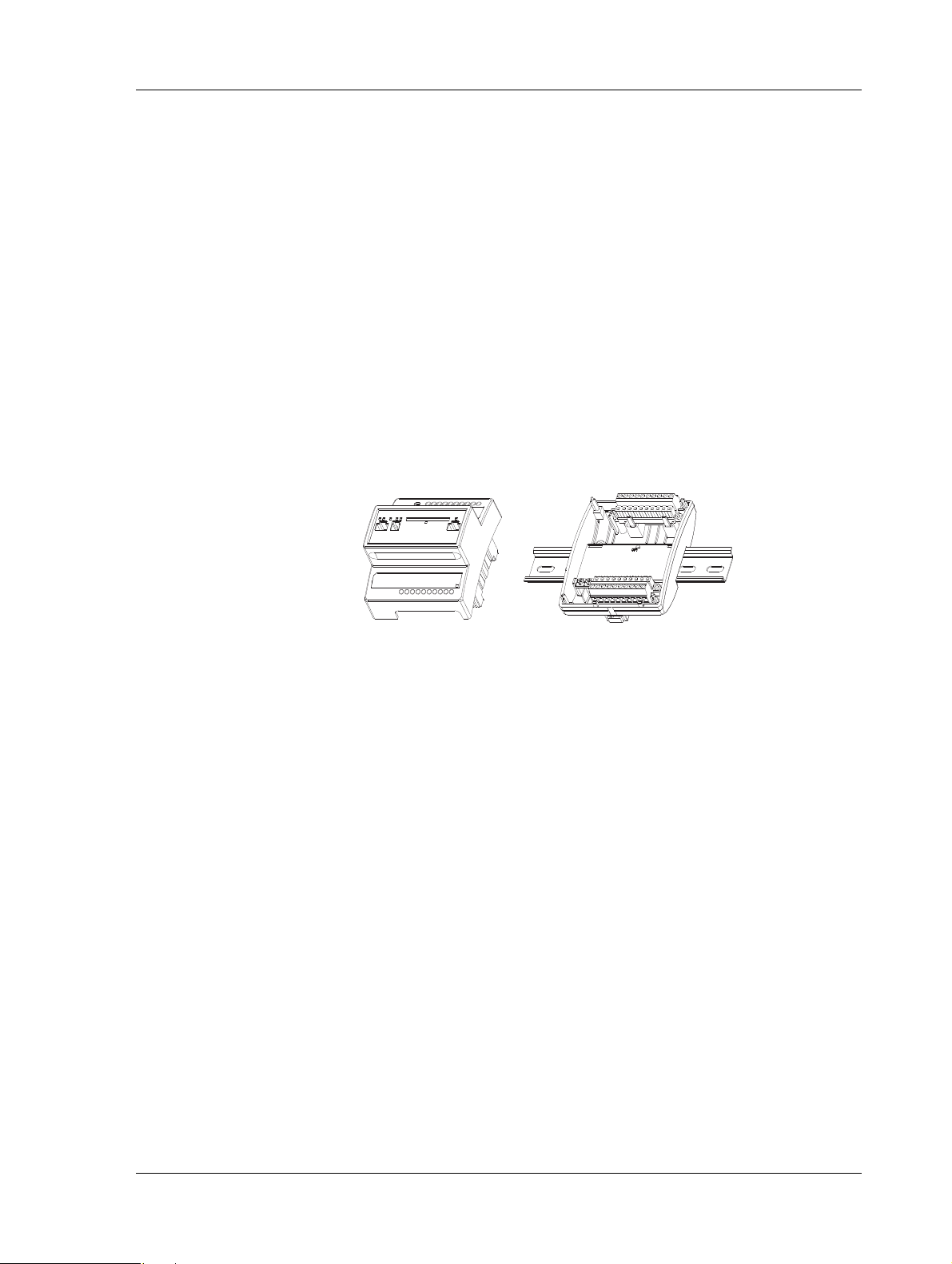
The Xenta device is designed around a microprocessor. The module
consists of two parts, an electronics unit containing the circuit boards
and contacts, and a terminal part including the terminal blocks.
Fig. 2.1: The Xenta device – Electronics and terminal.
• Power Outage Protection – Settings like configurations and web
pages are stored in the non-volatile (flash) memory and will not be
lost in the event of a power outage. A built-in capacitor maintains
operation of the RAM memory for at least 72 hours in the event of
a power outage.
• Real Time Clock – The real time clock provides the internal event
log with a time stamp. The capacitor maintains operation of the
clock for at least 72 hours in the event of a power outage.
• Mounting – The Xenta device is cabinet mounted on a TS 35 mm
norm rail EN 50022.
To simplify commissioning, the terminal part can be pre-mounted
in the cabinet.
If the Xenta device is to be wall-mounted, a wide range of standardized boxes are available.
Schneider Electric Buildings AB, Feb 2011 17 (134)
04-00071-04-en
Page 18
2 TAC Xenta 500/700/911/913 TAC Xenta 500/700/911/913, Product Manual
1 2345678910
11
12 13 14 15 16 17 18 19 20
21
22
23
24
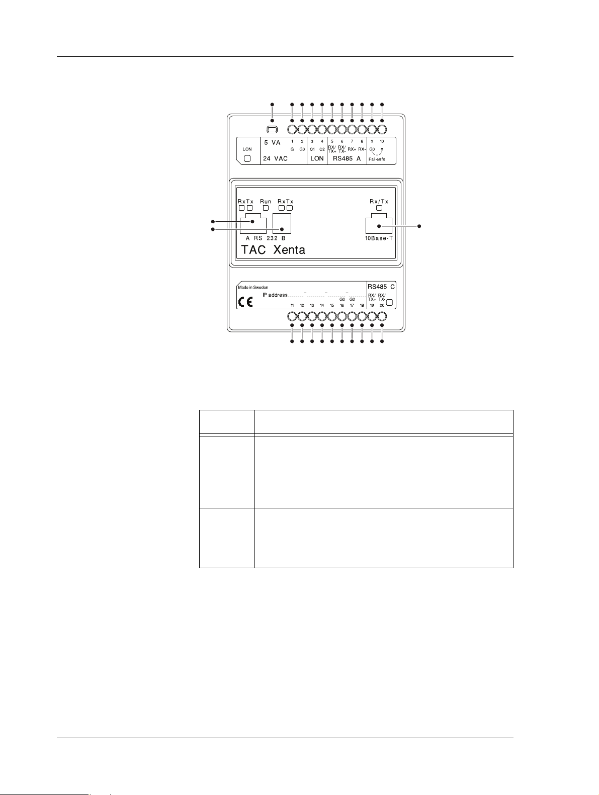
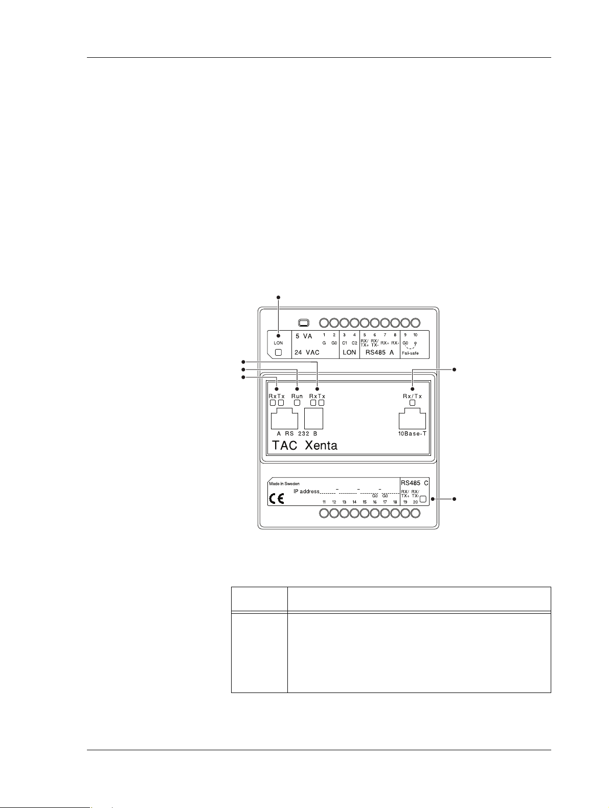
2.1.1 Communication Interface
Fig. 2.2: Connections on the Xenta device.
Table 2.1: Connections on the Xenta device.
Position Description
1–2 Power supply. Minimum cross-sectional area 0.75 mm2
(AWG-19).
• 1 (G) – 24 V AC (or DC+)
• 2 (G0) – Ground
3–4 LonWorks TP/FT-10 connection.
•3 (C1)
•4 (C2)
18 (134) Schneider Electric Buildings AB, Feb 2011
04-00071-04-en
Page 19
TAC Xenta 500/700/911/913, Product Manual 2 TAC Xenta 500/700/911/913
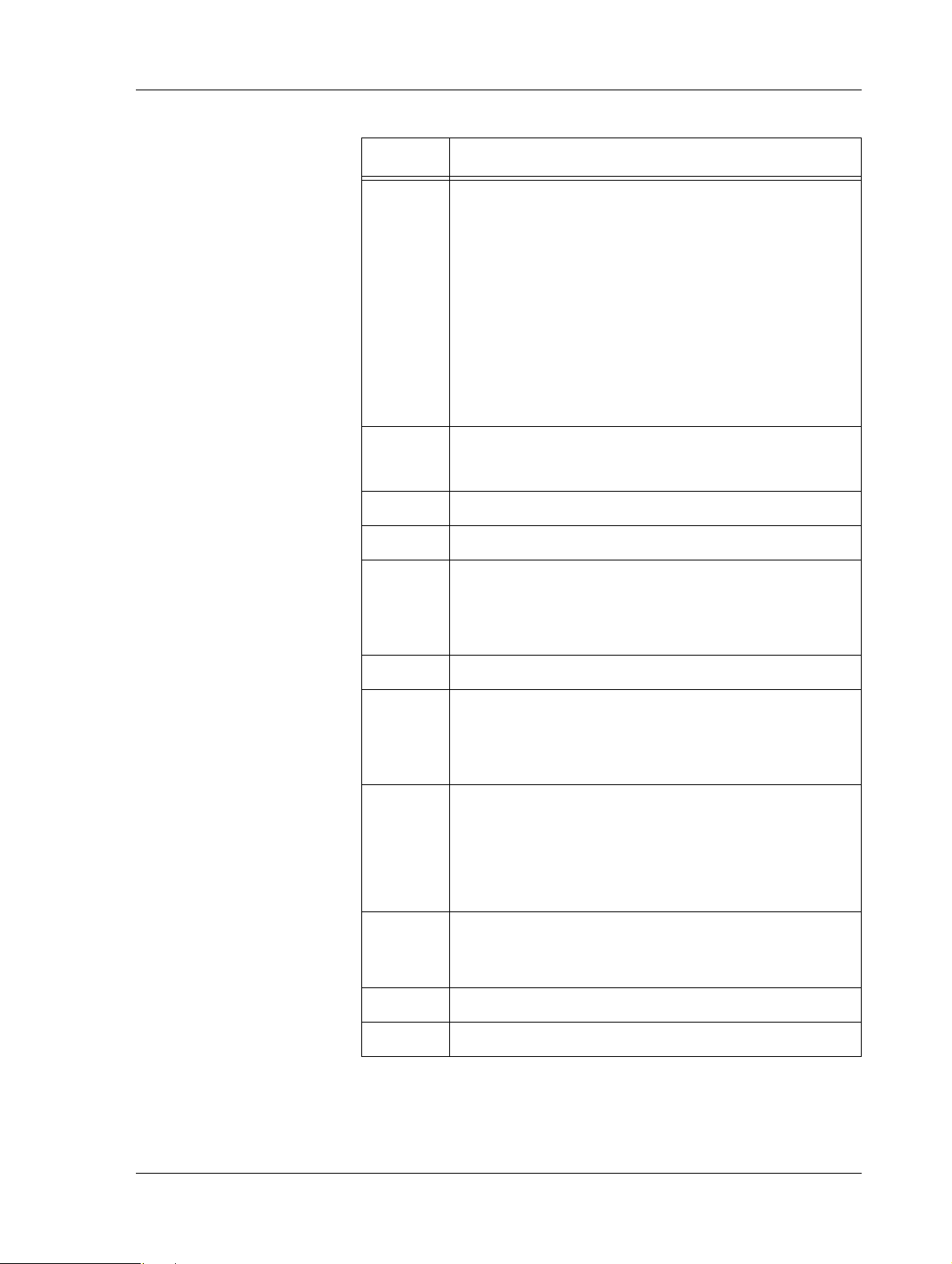
Table 2.1: Connections on the Xenta device. (Contd.)
Position Description
5–8
Internal
port A
RS-485 A connection.
•5 (RX/TX+)
• 6 (RX/TX-)
•7 (RX+)
•8 (RX-)
Note that the interface RS-232 A (position 21) and
interface RS-485 A (position 5–8) are internally connected to port A on the processor. Only one should be
connected.
9 Ground.
•9 (G0)
10 Fail-safe.
11–15 Unused.
16–17 Ground.
•16 (G0)
•17 (G0)
18 Unused.
19–20
Internal
port C
RS-485 C (SDLC) connection.
• 19 (RX/TX+)
• 20 (RX/TX-)
21
Internal
port A
RS-232 A connection.
Note that the interface RS-232 A (position 21) and
interface RS-485 A (position 5–8) are internally connected to port A on the processor. Only one should be
connected.
22
RS-232 B console connection.
Internal
port B
23 Ethernet 10Base-T connection.
24 Service pin.
Schneider Electric Buildings AB, Feb 2011 19 (134)
04-00071-04-en
Page 20

2 TAC Xenta 500/700/911/913 TAC Xenta 500/700/911/913, Product Manual
Caution
• G0 equals GROUND.
• Only G0 may be connected to protective ground.
20 (134) Schneider Electric Buildings AB, Feb 2011
04-00071-04-en
Page 21
TAC Xenta 500/700/911/913, Product Manual 2 TAC Xenta 500/700/911/913
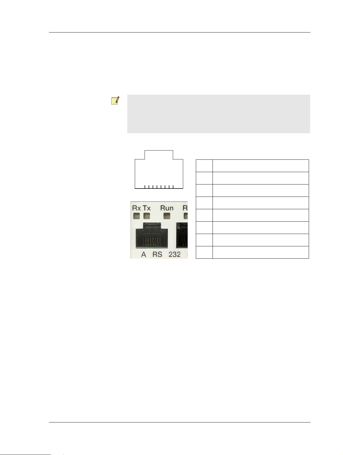
Table 2.2: Port pins – RS-232 A.
1 CTS/RI (input)
2 RTS (output)
3 TxD (output)
4 RxD (input)
5Ground
6 DSR (input)
7 DCD (input)
8DTR (output)
2.1.2 Port Pins
Serial Port – RS-232 A
The RS-232 A port (position 21) is used for serial communication
between the Xenta device and the connected unit. The connector is an
8-pin modular jack (RJ-45).
Note
• The interface RS-232 A (position 21) and interface RS-485 A
(position 5–8) are internally connected to port A on the processor. Only one should be connected.
The port uses the following signals:
87654321
Fig. 2.3: Connection using hardware signals for modem communication.
Schneider Electric Buildings AB, Feb 2011 21 (134)
04-00071-04-en
Page 22
2 TAC Xenta 500/700/911/913 TAC Xenta 500/700/911/913, Product Manual
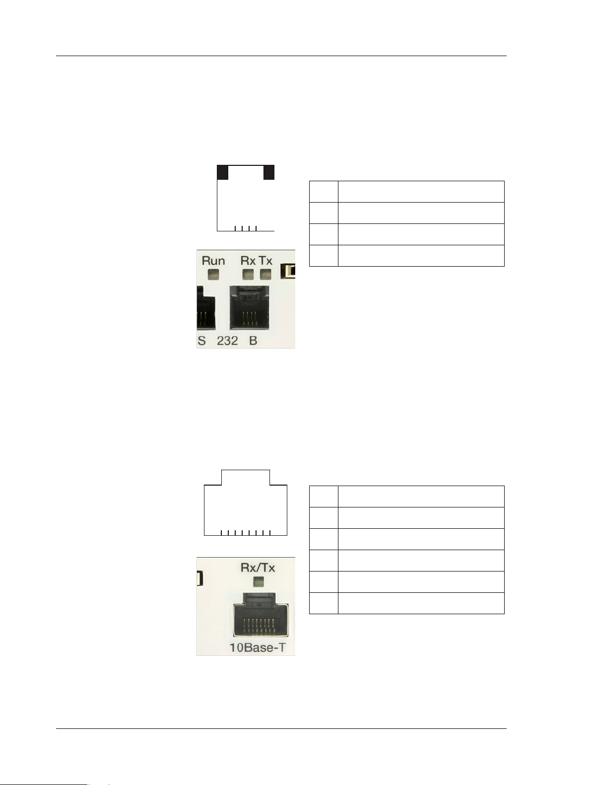
Table 2.3: Port pins – RS-232 B
1 TxD (output)
2 RxD (input)
3 Not used
4Ground
Table 2.4: Port pins – 10Base-T
1TX+
2TX3RX+
4–5 Connected to ground via 75 ohms
6RX7–8 Connected to ground via 75 ohms
Serial Port – RS-232 B
The RS-232 B port is used for communication between the Xenta
device and a computer. It is used for configuration of the Xenta device
using Windows HyperTerminal. The connector is a 4-pin modular jack
(RJ-10).
The port uses the following signals:
4321
Fig. 2.4: Connection using basic RS-232 signals, primarily intended for a
computer running, for example Windows HyperTerminal during the
configuration phase.
Ethernet Port – 10Base-T
The Ethernet 10Base-T port is used for communication between the
Xenta device and the TCP/IP network.
The port uses the following signals:
87654321
Fig. 2.5: Connection for a LAN (Ethernet) cable.
22 (134) Schneider Electric Buildings AB, Feb 2011
04-00071-04-en
Page 23
TAC Xenta 500/700/911/913, Product Manual 2 TAC Xenta 500/700/911/913
1
4
3
2
6
5
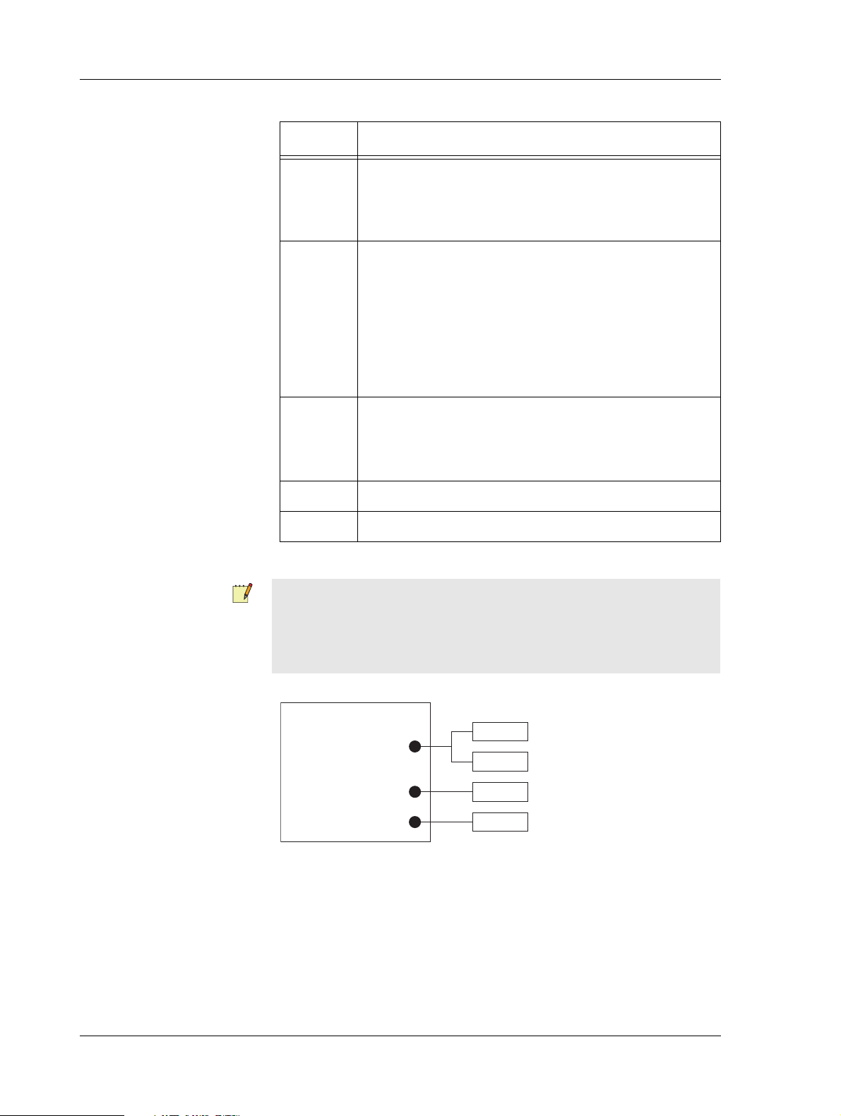
2.1.3 Fail-Safe State
The Xenta can enter a fail-safe state if a severe problem arises in the system program.
The unit can be forced into fail-safe mode by shorting terminals 9 and
10 in Fig. 2.2 during power-up. This can be useful if the system program
experiences problems.
The overall Run indicator (position 3 in Fig. 2.6) will show a steady red
light in the fail-safe state.
2.1.4 LEDs
A number of light-emitting diodes (LEDs) on the Xenta device indicate
that the application program is running and when communication is in
progress.
Fig. 2.6: LEDs on the Xenta device.
Table 2.5: LEDs on the Xenta device.
Position Description
1 Neuron status indicator
Schneider Electric Buildings AB, Feb 2011 23 (134)
04-00071-04-en
•Off – Normal mode
• Red, blinking – Unconfigured mode
• Red, steady – Hardware fault
Page 24
2 TAC Xenta 500/700/911/913 TAC Xenta 500/700/911/913, Product Manual
Serial Ports
A
C
B
Processor
RS-232
RS-485
RS-232
RS-485
Por t 21
Port pins 5, 6 (7, 8)
Por t 22
Port pins 19, 20
Table 2.5: LEDs on the Xenta device. (Contd.)
Position Description
2 Serial RS-232 B port activity indicators:
• RX – Indicates that data is received
• TX – Indicates that data is transmitted
3 Overall Run indicator
• Green, steady – Normal mode
• Green, blinking – Start mode
• Red, steady – Fail-safe mode
(see description below)
• Red, blinking – Unit fault
4 Serial RS-232 A port activity indicators:
• RX – Indicates that data is received
• TX – Indicates that data is transmitted
5 Serial RS-485 C port activity indicator.
6 Ethernet 10Base-T activity indicator
Note
• The LEDs for the RS-232 A interface (position 4) do not indicate
communication when using the RS-485 A interface although
internal port A is used for both.
Fig. 2.7: Internal serial ports and RS-232/485 interfaces.
24 (134) Schneider Electric Buildings AB, Feb 2011
04-00071-04-en
Page 25

TAC Xenta 500/700/911/913, Product Manual 2 TAC Xenta 500/700/911/913
2.2 Configuring the TAC Xenta 500/700/911/913
The technician uses Microsoft Windows and HyperTerminal to initialize and configure the Xenta.
• For more information on how to connect the Xenta 511, see
Section 4.1, “Configuration Phase”, on page 43.
• For more information on how to connect the Xenta 527, see
Section 5.1, “Configuration Phase”, on page 53.
• For more information on how to connect the Xenta 555, see
Section 6.1, “Configuration Phase”, on page 67.
• For more information on how to connect the Xenta 701/711/721,
see Section 7.1, “Configuration Phase”, on page 79.
• For more information on how to connect the Xenta 731, see
Section 8.1, “Configuration Phase”, on page 89.
• For more information on how to connect the Xenta 911, see
Section 10.1, “Configuration Phase”, on page 105.
• For more information on how to connect the Xenta 913, see
Section 11.1, “Configuration Phase”, on page 113.
2.2.1 Configuration Data
To configure the Xenta, the following information should be obtained
from the network administrator:
• DHCP is used or not used
• IP address (only if DHCP is not used)
• Subnet mask (only if DHCP is not used)
• Default gateway
•DNS server
• Web site name (can be set later, using XBuilder)
• Domain name (only used as information)
• Host name (only used as information)
This information is used once you have connected to the Xenta using
HyperTerminal and a serial cable (null modem cable).
Schneider Electric Buildings AB, Feb 2011 25 (134)
04-00071-04-en
Page 26
2 TAC Xenta 500/700/911/913 TAC Xenta 500/700/911/913, Product Manual
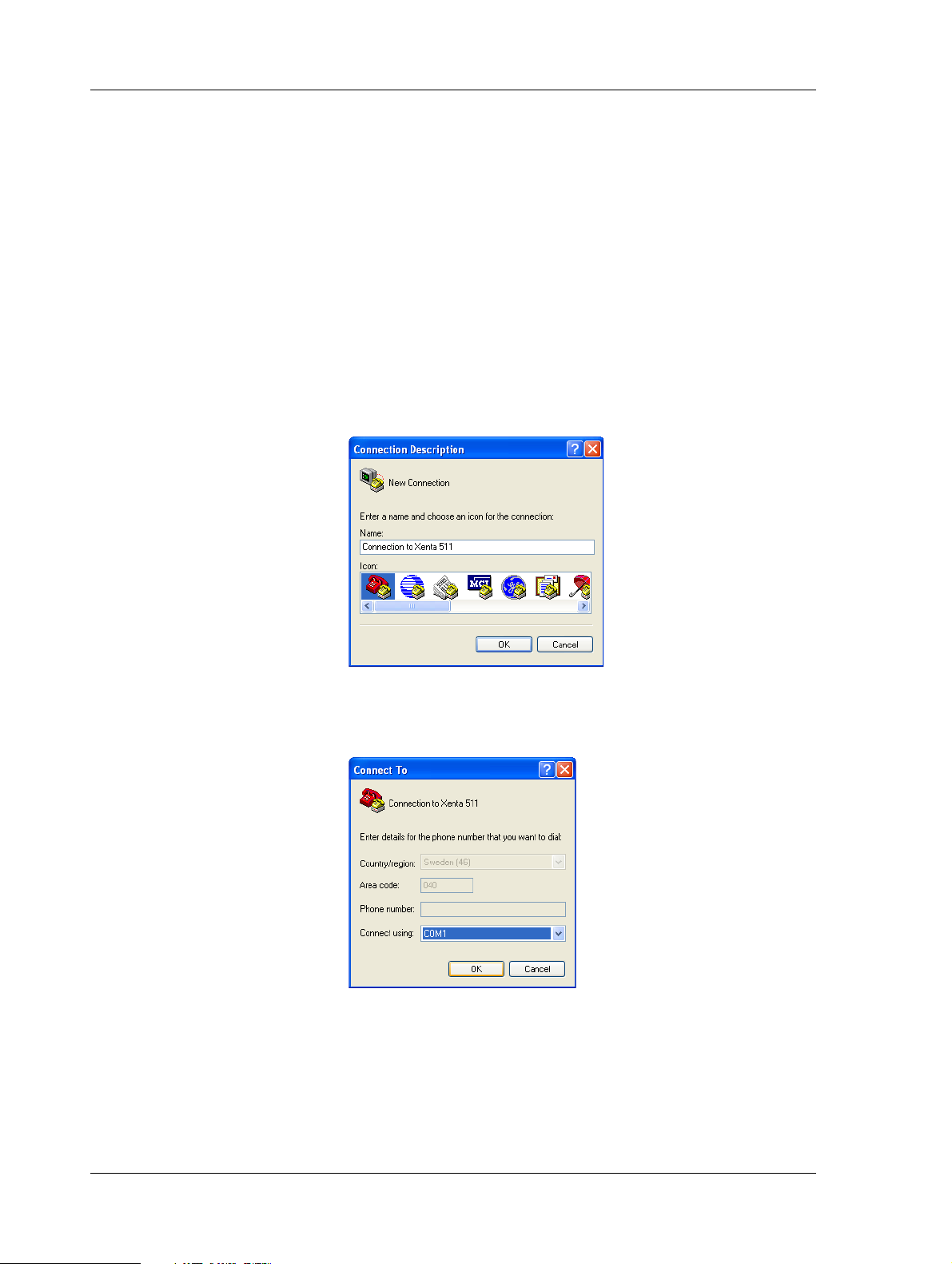
2.2.2 Configuring Windows HyperTerminal
When you use Windows HyperTerminal you need to set up a connection. Once created it can be used when required. In the example below
a Xenta 511 is configured.
To configure Windows HyperTerminal
1 Connect the Xenta to the engineering PC.
2 On the Start menu, point to All Programs, point to Accessories,
point to Communications, and then click HyperTerminal.
3 In the Connection Description dialog box, in the Name box, type
a name that describes the connection. In the example “Connection
to Xenta 511”.
4 In the Icon box, click the required icon.
5 Click OK.
6 In Connect To dialog box, in the Connect using list, click the
COM port used in step 1 above.
7 Click OK.
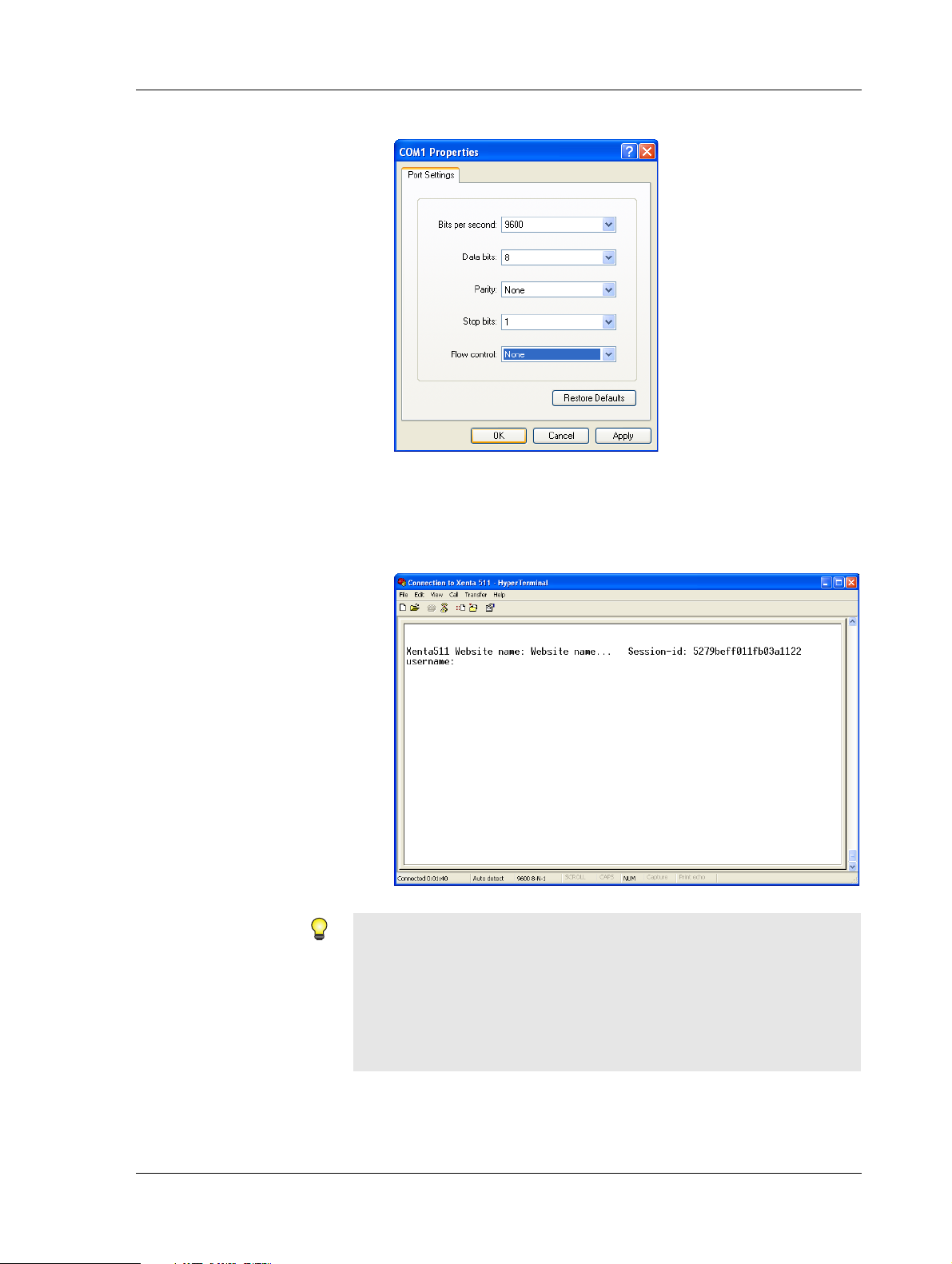
8 In the COM1 Properties dialog box, in the Bits per second list,
click 9600.
26 (134) Schneider Electric Buildings AB, Feb 2011
04-00071-04-en
Page 27
TAC Xenta 500/700/911/913, Product Manual 2 TAC Xenta 500/700/911/913
9 In the Flow control list, click None.
10 Click OK.
11 On the File menu, click Save to save the HyperTerminal connec-
tion. The HyperTerminal for the Xenta is now ready to use.
12 Press ENTER to activate the command prompt.
Tips
• To reopen the HyperTerminal connection to the Xenta, click
Start, point to All Programs, point to Accessories, point to
Communications, point to HyperTerminal and then click Connection to Xenta 511. ht .
• You can also click Open on the File menu in HyperTerminal.
Schneider Electric Buildings AB, Feb 2011 27 (134)
04-00071-04-en
Page 28
2 TAC Xenta 500/700/911/913 TAC Xenta 500/700/911/913, Product Manual
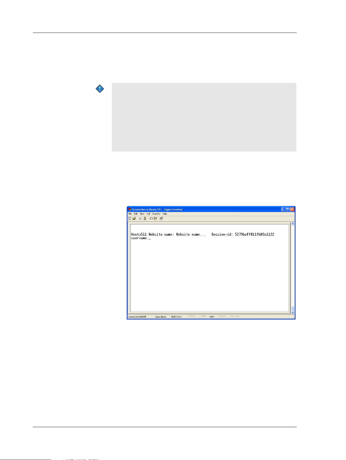
2.2.3 Configuring the TAC Xenta
The configuration parameters for the Xenta are entered using HyperTerminal. The parameters enable the Xenta to communicate using its
TCP/IP port.
Important
• Because the Xenta’s TCP/IP default parameters are set at the factory, you can immediately access it using a web browser and
change the parameters without having to use HyperTerminal.
The default parameters are:
• IP address: 192.168.255.2
• Subnet mask: 255.255.255.0
To configure the TAC Xenta
1 Start Windows HyperTerminal using the connection created in
Section 2.2.2, “Configuring Windows HyperTerminal”, on
page 26.
2 Press ENTER to activate the command prompt.
3 Type the user name “root” and press ENTER.
28 (134) Schneider Electric Buildings AB, Feb 2011
04-00071-04-en
Page 29
TAC Xenta 500/700/911/913, Product Manual 2 TAC Xenta 500/700/911/913
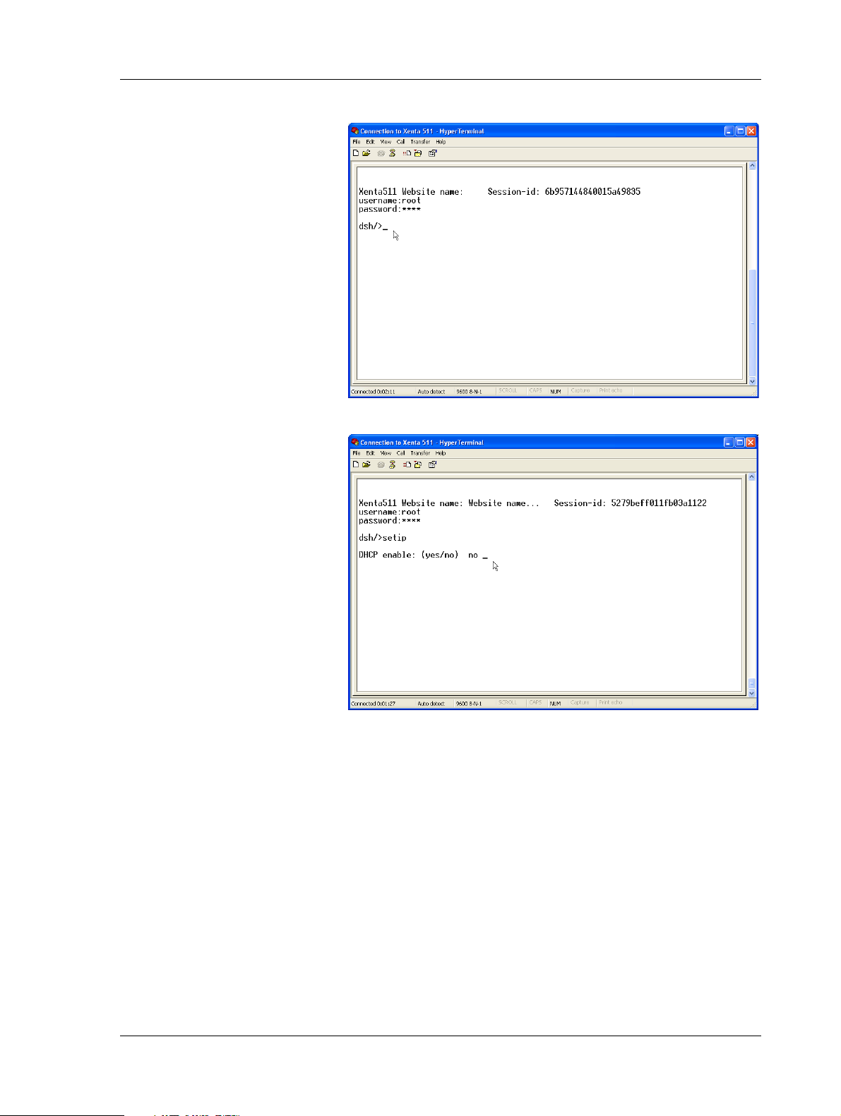
4 Type the password “root” and press ENTER.
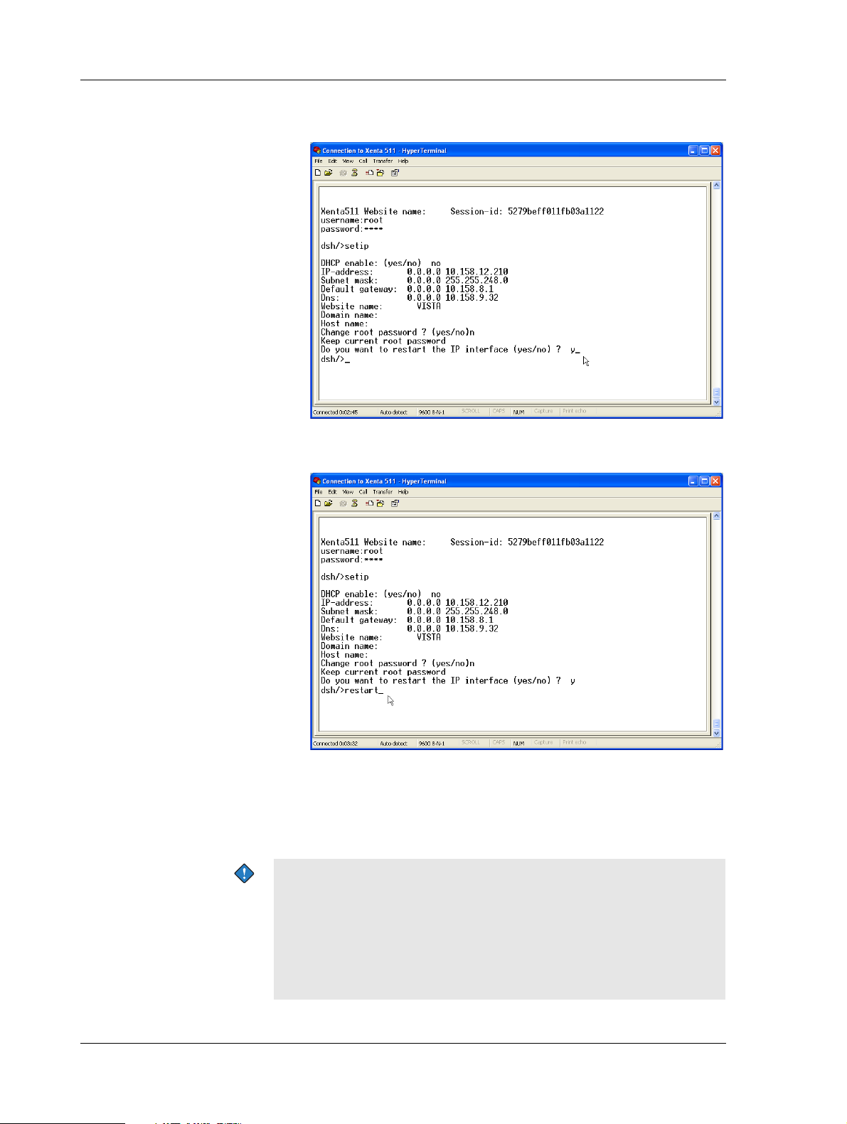
5 Type the command “setip” and press ENTER.
6 Type the configuration parameters, collected in Section 2.2.1,
“Configuration Data”, on page 25. Press ENTER after each entry.
Schneider Electric Buildings AB, Feb 2011 29 (134)
04-00071-04-en
Page 30
2 TAC Xenta 500/700/911/913 TAC Xenta 500/700/911/913, Product Manual
In the example, the configuration parameters appear as follows.
The root password is not changed.
7 T ype the command “restart” and press ENTER, to activate the new
configuration parameters.
8 Quit HyperTerminal.
The Xenta is now configured to communicate over TCP/IP, this means
that you can access the Xenta through a web browser and that you can
send web pages to the Xenta using XBuilder.
Important
• The password can be changed from a configuration page on the
web site in the Xenta.
• The user name and the password are used by the operator when
logging on to the web site and by XBuilder when sending the
project to the Xenta.
30 (134) Schneider Electric Buildings AB, Feb 2011
04-00071-04-en
Page 31

TAC Xenta 500/700/911/913, Product Manual 2 TAC Xenta 500/700/911/913
2.3 Verifying the TAC Xenta Communication
Once the Xenta has been configured with respect to its address on the
TCP/IP network, it can be accessed through a web browser.
• For more information on how to connect the Xenta 511, see
Section 4.2, “Engineering Phase”, on page 45.
• For more information on how to connect the Xenta 527, see
Section 5.2, “Engineering Phase”, on page 55.
• For more information on how to connect the Xenta 555, see
Section 6.2, “Engineering Phase”, on page 69.
• For more information on how to connect the Xenta 701/711/721,
see Section 7.2, “Engineering Phase”, on page 81.
• For more information on how to connect the Xenta 731, see
Section 8.2, “Engineering Phase”, on page 91.
• For more information on how to connect the Xenta 911, see
Section 10.2, “Engineering Phase”, on page 106.
• For more information on how to connect the Xenta 913, see
Section 11.2, “Programming and Operating Phase”, on page 115.
Schneider Electric Buildings AB, Feb 2011 31 (134)
04-00071-04-en
Page 32

2 TAC Xenta 500/700/911/913 TAC Xenta 500/700/911/913, Product Manual
2.3.1 Accessing the TAC Xenta
The Xenta is accessed using an standard web browser.
To access the TAC Xenta
1 Start Internet Explorer.
2 In the Address box, type the IP address of the Xenta. In the ex am-
ple “10.158.12.210”.
3 Press ENTER.
A security alert appears, similar to the following figure, with information about the site’s security certificate.
4 Click Yes.
5 In the Username box, type “root”.
32 (134) Schneider Electric Buildings AB, Feb 2011
04-00071-04-en
Page 33

TAC Xenta 500/700/911/913, Product Manual 2 TAC Xenta 500/700/911/913
6 In the Password box, type the password. In the example, “root”.
7 Click Login.
The default web page in the Xenta appears.
Note
• A java applet security dialog warning may be displayed. Click
Yes in the dialog.
Schneider Electric Buildings AB, Feb 2011 33 (134)
04-00071-04-en
Page 34

2 TAC Xenta 500/700/911/913 TAC Xenta 500/700/911/913, Product Manual
2.3.2 Changing the Root Password
The default password for the system administrator is widely known. To
avoid unauthorized access to the system the password has to be
changed. You can change the password using the Change Password
page on the Xenta web site.
To change the password
1 In the navigator, expand Configuration-User Administrator, and
click Change Password.
2 In the Old password box, type the old password. In the example,
“root”.
3 In the New password box, type the new password. In the example,
“seagull3”.
4 In the Confirm new password box, confirm the new password.
5 Click Save.
Use the new password the next time you log on as system administrator.
34 (134) Schneider Electric Buildings AB, Feb 2011
04-00071-04-en
Page 35

TAC Xenta 500/700/911/913, Product Manual 2 TAC Xenta 500/700/911/913
2.4 Temporary Login ID
If you do not have access to the root password when you try to connect
to a Xenta 500/700/913, a temporary user name and password can be
used. The temporary password is generated by based on the Session ID
displayed on the Login page.
Send the Session ID to helpdesk@tac.com, which generates and returns
a temporary password. Then type the Session ID in the Username box
and the temporary password in the Password box.
Tip
• You can select the text on the login page, copy it and then paste it
into the e-mail message and the Username box.
The Session ID changes each day, so the temporary password is only
valid on the day it is generated.
Schneider Electric Buildings AB, Feb 2011 35 (134)
04-00071-04-en
Page 36

2 TAC Xenta 500/700/911/913 TAC Xenta 500/700/911/913, Product Manual
2.5 Upgrading the System Program
The Xenta system program can be upgraded via the IP network from a
computer running the installation program. The installation program is
distributed by Schneider Electric. In the example the Xenta 511 will be
upgraded.
Note
• To upgrade the system program of the Xenta device you must
first configure the Xenta using Windows HyperTerminal. For
more information on how to configure the Xenta, see
Section 2.2, “Configuring the TAC Xenta 500/700/911/913”, on
page 25.
To upgrade the system program
1 Connect the Xenta and a computer to a TCP/IP network according
to the figure.
TCP/IP TCP/IP
2 Obtain the installation program from Schneider Electric’ s web site
or from the TAC Software CD-ROM.
3 Double-click the installation program to start the installation.
The following screen shots show the installation procedure for a
Xenta 511 but they are similar for other Xenta devices.
4 Read the instructions.
5 If the requirements are met, click Next.
36 (134) Schneider Electric Buildings AB, Feb 2011
04-00071-04-en
Page 37

TAC Xenta 500/700/911/913, Product Manual 2 TAC Xenta 500/700/911/913
6 Select temporary folder for the installation program.
7 Click Next.
8 Select skin.
9 Click Next.
10 Select which kind of installation you want to carry out. In our
example, select Install full system.
Schneider Electric Buildings AB, Feb 2011 37 (134)
04-00071-04-en
Page 38

2 TAC Xenta 500/700/911/913 TAC Xenta 500/700/911/913, Product Manual
11 Click Next.
12 In the TAC Xenta 511 target unit parameters dialog box, in the
Username box, type root.
13 In the Password box, type the password for root.
14 In the IP address box, type the IP address (or the URL address) of
the Xenta device.
15 Click Next.
16 Read the list of actions that will be carried out during the installa-
tion.
38 (134) Schneider Electric Buildings AB, Feb 2011
04-00071-04-en
Page 39

TAC Xenta 500/700/911/913, Product Manual 2 TAC Xenta 500/700/911/913
17 Click Yes.
18 Click Finish to complete the installation.
Schneider Electric Buildings AB, Feb 2011 39 (134)
04-00071-04-en
Page 40

2 TAC Xenta 500/700/911/913 TAC Xenta 500/700/911/913, Product Manual
40 (134) Schneider Electric Buildings AB, Feb 2011
04-00071-04-en
Page 41

TAC Xenta 500/700/911/913, Product Manual 3 Connecting the TAC Xenta to Your Network
3 Connecting the TAC Xenta to Your
Network
The Xenta integrates with your building control system by communicating across the Ethernet using TCP/IP transport protocols.
In order for the Xenta to successfully establish communications with
your building control system, certain network criteria must be met.
More specifically, the ports required for proper communication with
these systems must be open and available to the Xenta . The Xenta uses
the following communication ports:
• Port 80 (HTTP access, configurable)
• Port 443 (HTTPS access, configurable)
• Port 20/21 (FTP access)
• Port 25 (SMTP access)
• Port 80 (Status Viewer, Alarm Viewer and Graphics Viewer)
• Port 1068 (LTA for Vista)
• Port 161 (SNMP access)
Schneider Electric Buildings AB, Feb 2011 41 (134)
04-00071-04-en
Page 42

3 Connecting the TAC Xenta to Your Network TAC Xenta 500/700/911/913, Product Manual
3.1 Alternative Port Settings
3.1.1 HTTP and HTTPS
Perhaps you are unable to make the necessary configuration changes to
your proxies/firewalls because of restrictions imposed by your company’s network security policies. In this case, you have the option of
choosing different numbers for the HTTP and HTTPS communication
ports shown above.
The following steps describe how to select other communication ports:
1 From the web browser, expand the navigation tree as shown in the
following figure and select
HTTP Server.
2 Set the HTTP and HTTPS communication port assignments to the
appropriate values.
3 Accept your settings by selecting
4 Configure your network to allow communication on the ports you
assigned to the Xenta.
5 Verify that the Xenta can now successfully communicate across
the Internet and with your building control systems.
Save & Restart.
42 (134) Schneider Electric Buildings AB, Feb 2011
04-00071-04-en
Page 43

TAC Xenta 500/700/911/913, Product Manual 4 TAC Xenta 511
RS-232
Windows HyperTerminal
4 TAC Xenta 511
A Xenta 511 can be configured as a web-based presentation system for
LonWorks networks. Using a standard web browser, the operator can
easily view and control the devices in the LonWorks network.
4.1 Configuration Phase
The technician uses Microsoft Windows and HyperTerminal via an
RS-232 connection to initialize and configure the Xenta 511. For more
information on how to initialize and configure the Xenta 511,
see Section 2.2, “Configuring the TAC Xenta 500/700/911/913”, on
page 25.
Fig. 4.1: Windows HyperTerminal communicating with a TAC Xenta 511
using RS-232 during the configuration phase.
Schneider Electric Buildings AB, Feb 2011 43 (134)
04-00071-04-en
Page 44

4 TAC Xenta 511 TAC Xenta 500/700/911/913, Product Manual
12
4.1.1 Connections, configuration
Cables that can be ordered from Schneider Electric are ordered as cable
kits. Below you find information on which kit to order and how to connect the cables.
Required Cable Kit
Part. No. 007309200.
Fig. 4.2: Connections during the configuration phase.
Pos. Description Qty Part No.
1 DB9/Female-to-RJ45/Female adapter connecting the computer
serial port to the cable directly below.
2 Serial cable (null modem cable) connecting adapter directly above
to the Xenta serial port RS-232 B.
1. Part of cable kit no. 007309200. The cable kit also contains a RJ-45-to-RJ-45 rollover cable
(3-781-0118-0). This cable is not needed during the configuration phase.
1 3-621-3056-0
1 3-781-0128-0
1
1
44 (134) Schneider Electric Buildings AB, Feb 2011
04-00071-04-en
Page 45

TAC Xenta 500/700/911/913, Product Manual 4 TAC Xenta 511
ial
l
4.2 Engineering Phase
The technician uses XBuilder to program the Xenta 511 via the TCP/IP
network. To access the Xenta 511 web site a standard web browser is
used.
LonTalk
TCP/IP
TAC XBuilder
Web browser
Fig. 4.3: TAC XBuilder or a web browser communicating with a TAC
Xenta 511 using IP during the engineering phase.
Modbus Master, ser
Modbus Slave, seria
Modbus TCP Client
Schneider Electric Buildings AB, Feb 2011 45 (134)
04-00071-04-en
Page 46

4 TAC Xenta 511 TAC Xenta 500/700/911/913, Product Manual
4.2.1 Connections, engineering
Below you find information on which cables to use and how to connect
the cables.
3
4
12
TCP/IP
TxD 3
RxD 4
Cr 5
5
Fig. 4.4: Connections during the engineering phase.
Pos. Description Qty Part No.
11TP UTP/STP CAT.6 RJ-45 cable connecting the computer network
port to the TCP/IP network.
1
TP UTP/STP CAT.6 RJ-45 cable connecting the TCP/IP network to
2
the Xenta 10Base-T port.
3 Cable connecting the Xenta port pins 3–4 to the LonWorks device.
For more information on cables approved by Echelon,
see www.echelon.com.
2
Cable connecting the Xenta RS485Aport pins 5–6 (5–8) to the
4
Modbus device.
For more information on cable requirements, see the Modbus equipment documentation.
1N/A
1N/A
1N/A
1N/A
2
Cable connecting the Xenta port RS-232 A to the Modbus device.
5
1N/A
For more information on cable requirements, see the Modbus equipment documentation.
1. TAC Xenta 511does not support Ethernet MDI, a crossover cable may be required.
2. Only one may be connected.
46 (134) Schneider Electric Buildings AB, Feb 2011
04-00071-04-en
Page 47

TAC Xenta 500/700/911/913, Product Manual 4 TAC Xenta 511
Web browser
TCP/IP
LonTalk
Modbus Master, serial
Modbus Slave, serial
Modbus TCP Client
4.3 Operating Phase
The operator uses a standard web browser to view and control the
devices in the LonWorks network, either via a directly connected or
using a dialed-up connection.
4.3.1 Directly Connected
The operator uses a standard web browser to view and control the
devices in the LonWorks network.
Fig. 4.5: A web browser communicating with a TAC Xenta 511 using
TCP/IP during the operating phase.
Schneider Electric Buildings AB, Feb 2011 47 (134)
04-00071-04-en
Page 48

4 TAC Xenta 511 TAC Xenta 500/700/911/913, Product Manual
TxD 3
RxD 4
Cr 5
TCP/IP
12
5
3
4
4.3.2 Connections, operation directly
Below you find information on which cables to use and how to connect
the cables.
Fig. 4.6: Connections during the operating phase.
Pos. Description Qty Part No.
11TP UTP/STP CAT.6 RJ-45 cable connecting the computer network
port to the TCP/IP network.
1
TP UTP/STP CAT.6 RJ-45 cable connecting the TCP/IP network to
2
the Xenta 10Base-T port.
3 Cable connecting the Xenta port pins 3–4 to the LonWorks device.
For more information on cables approved by Echelon,
see www.echelon.com.
2
Cable connecting the Xenta RS485Aport pins 5–6 (5–8) to the
4
Modbus device.
For more information on cable requirements, see the Modbus equipment documentation.
2
Cable connecting the Xenta port RS-232 A to the Modbus device.
5
For more information on cable requirements, see the Modbus equipment documentation.
1. TAC Xenta 511does not support Ethernet MDI, a crossover cable may be required.
2. Only one may be connected.
1N/A
1N/A
1N/A
1N/A
1N/A
48 (134) Schneider Electric Buildings AB, Feb 2011
04-00071-04-en
Page 49

TAC Xenta 500/700/911/913, Product Manual 4 TAC Xenta 511
RS232
ISP Modem
Web browser
TCP/IP
4.3.3 Dialed-Up, operation
The operator uses a standard web browser to view and control the
devices in the LonWorks network, using a dialed-up connection via
RS-232 with the possibility to use a TCP/IP network.
RS232
Web browser
RS232
Fig. 4.7: Dialed-up connection.
Fig. 4.8: Dialed-up connection via TCP/IP.
Schneider Electric Buildings AB, Feb 2011 49 (134)
04-00071-04-en
Page 50

4 TAC Xenta 511 TAC Xenta 500/700/911/913, Product Manual
Modem
3
4
21
5
4.3.4 Connections, operation dial-up
Cables that can be ordered from Schneider Electric are ordered as cable
kits. Below you find information on which kit to order and how to connect the cables.
Required Cable Kit
Part. No. 007309160.
Fig. 4.9: Connections during the engineering phase.
Pos. Description Qty Part No.
1 DB25/Male-to-RJ45/Female adapter connecting the modem serial
port to the cable directly below.
22RJ-45-to-RJ-45 rollover cable connecting the adapter to the Xenta
serial port RS-232 A.
3 Cable connecting the Xenta port pins 3–4 to the LonWorks device.
For more information on cables approved by Echelon,
see www.echelon.com
2
4
Cable connecting the Xenta port pins 5–6 (5–8) to the Modbus
device.
For more information on cable requirements, see the Modbus equipment documentation.
5 TP UTP/STP CAT.6 RJ-45 cable connecting the TCP/IP to the
Xenta 10Base-T port.
1. Part of cable kit no. 007309160.
2. Only one should be connected.
1 3-621-3052-0
1 3-781-0118-0
1N/A
1N/A
1N/A
1
1
50 (134) Schneider Electric Buildings AB, Feb 2011
04-00071-04-en
Page 51

TAC Xenta 500/700/911/913, Product Manual 4 TAC Xenta 511
4.4 Port Usage
If a Xenta 511 and the IP network are located on opposite sides of one
or several firewalls, these firewalls must be configured to allow traffic
through.
The Xenta 511 uses the following ports:
Table 4.1: Port Usage
Local/
Protocol IP Ports
FTP 20, 21 Local No File transfer protocol.
HTTP 80 Local Yes HTTP traffic.
HTTPS 443 Local Yes HTTP traffic over SSL, secure socket
Remote
Xenta
Port
Configurable Comments
layer.
DHCP Server 67 Remote No
DHCP Client 68 Local No
DNS 53 Remote No
VarTransfer-http 80 Local/
Remote
VarTransfer-TCP
VarTransfer-UDP
SNMP 161 Local No Network management protocol
SNMP Trap 162 Remote No Network management protocol
SMTP 25 Remote No Mail protocol.
LTA IP 1068 Local/
1233
9088/9089
Local/
Remote
Remote
Yes Dynamic data protocol, used by
applets to communicate on-line data.
The port number is the same as the
http port.
Dynamic data protocol, used between
No
Yes Protocol used between Vista Server
Xenta 500/700/913s that exchange
variable data.
(UDP).
(UDP).
and Xenta 511 operating as an LTA
port.
NTP, SNTP 123 Local/
Remote
Modbus TCP
Client
Schneider Electric Buildings AB, Feb 2011 51 (134)
04-00071-04-en
502 Remote Yes Modbus TCP client to a server or
No Time synchronization (UDP).
router on a network.
Page 52

4 TAC Xenta 511 TAC Xenta 500/700/911/913, Product Manual
52 (134) Schneider Electric Buildings AB, Feb 2011
04-00071-04-en
Page 53

TAC Xenta 500/700/911/913, Product Manual 5 TAC Xenta 527
RS-232
Windows HyperTerminal
5 TAC Xenta 527
A Xenta 527 can be configured as a web-based presentation system for
I/NET networks. Using a standard web browser, the operator can easily
view and control the devices in the LonW o rks network via the Internet
or a local intranet.
5.1 Configuration Phase
The technician uses Microsoft Windows and HyperTerminal via a
RS-232 connection to initialize and configure the Xenta 527. For more
information, see Section 2.2, “Configuring the
TAC Xenta 500/700/911/913”, on page 25.
Fig. 5.1: Windows HyperTerminal communicating with a TAC Xenta 527
using RS-232 during the configuration phase.
Schneider Electric Buildings AB, Feb 2011 53 (134)
04-00071-04-en
Page 54

5 TAC Xenta 527 TAC Xenta 500/700/911/913, Product Manual
12
5.1.1 Connections
Cables that can be ordered from Schneider Electric are ordered as cable
kits. Below you find information on which kit to order and how to connect the cables.
Required Cable Kit
Part. No. 007309200.
Fig. 5.2: Connections during the configuration phase.
Pos. Description Qty Part No.
1 DB9/Female-to-RJ45/Female adapter connecting the computer
serial port to the cable directly below.
2 Serial cable (null modem cable) connecting adapter directly above
to the Xenta serial port RS-232 B.
1. Part of cable kit no. 007309200. The cable kit also contains a RJ-45-to-RJ-45 rollover cable
(3-781-0118-0). This cable is not needed during the configuration phase.
1 3-621-3056-0
1 3-781-0128-0
1
1
54 (134) Schneider Electric Buildings AB, Feb 2011
04-00071-04-en
Page 55

TAC Xenta 500/700/911/913, Product Manual 5 TAC Xenta 527
TAC XBuilder
Web browser
TCP/IP
I/NET
LonTalk
Modbus Master, serial
Modbus Slave, serial
Modbus TCP Client
5.2 Engineering Phase
The technician uses XBuilder to program the Xenta 527 via the TCP/IP
network. To access the Xenta 527 web site a standard web browser is
used.
Fig. 5.3: TAC XBuilder or a web browser communicating with a TAC
Xenta 527 using IP during the engineering phase.
Schneider Electric Buildings AB, Feb 2011 55 (134)
04-00071-04-en
Page 56

5 TAC Xenta 527 TAC Xenta 500/700/911/913, Product Manual
LAN
WAN
TCP/IP
12
3
4
TxD 3
RxD 4
Cr 5
6
5
5.2.1 Connections
Below you find information on which cables to use and how to connect
the cables.
Fig. 5.4: Connections during the engineering phase.
56 (134) Schneider Electric Buildings AB, Feb 2011
04-00071-04-en
Page 57

TAC Xenta 500/700/911/913, Product Manual 5 TAC Xenta 527
Pos. Description Qty Part No.
11TP UTP/STP CAT.6 RJ-45 cable connecting the computer network
port to the TCP/IP network.
1
TP UTP/STP CAT.6 RJ-45 cable connecting the TCP/IP network to
2
the Xenta 10Base-T port.
3 Cable connecting the Xenta port pins 3–4 to the LonWorks device.
For more information on cables approved by Echelon,
see www.echelon.com.
2
I/NET Controller LAN cable connected to serial port RS-485 C.
4
Use either of the following wire types:
2
• 22 AWG (0.324 mm
) shielded, twisted pair, 5000' (1500 m)
maximum per segment, 150 Ω impedance, 9 pF/ft. conductor-to-conductor, 14 pF/ft. conductor-to-shield.
or
• 24 AWG (0.206 mm
2
) shielded, twisted pair, 4000' (1200 m)
maximum per segment, 120 Ω impedance, 13 pF/ft. conduc-
tor-to-conductor, 23 pF/ft. conductor-to-shield.
3
5
Cable connecting the Xenta port pins 5–6 (5–8) to the Modbus
device.
For more information on cable requirements, see the Modbus equipment documentation.
1N/A
1N/A
1N/A
1
Belden 9184
Belden 9841
1N/A
3
Cable connecting the Xenta port RS-232 A to the Modbus device.
6
1N/A
For more information on cable requirements, see the Modbus equipment documentation.
1. TAC Xenta 527 does not support Ethernet MDI, a crossover cable may be required.
2. Maintain proper polarity when connecting this cable to each device on the controller LAN.
3. Only one may be connected.
Schneider Electric Buildings AB, Feb 2011 57 (134)
04-00071-04-en
Page 58

5 TAC Xenta 527 TAC Xenta 500/700/911/913, Product Manual
ial
l
TCP/IP
12
3
4
TxD 3
RxD 4
Cr 5
6
5
5.3 Operating Phase
The operator uses a standard web browser to view and control the
devices in the LonWorks network, either via a directly connected or
using a dialed-up connection.
5.3.1 Directly Connected
The operator uses a standard web browser to view and control the LonWorks devices directly connected via TCP/IP.
I/NET
LonTalk
TCP/IP
Web browser
Fig. 5.5: A web browser communicating with a TAC Xenta 527 using
TCP/IP during the operating phase.
5.3.2 Connections
Modbus Master, ser
Modbus Slave, seria
Modbus TCP Client
Below you find information on which cables to use and how to connect
the cables.
Fig. 5.6: Connections during the operating phase.
58 (134) Schneider Electric Buildings AB, Feb 2011
04-00071-04-en
Page 59

TAC Xenta 500/700/911/913, Product Manual 5 TAC Xenta 527
Pos. Description Qty Part No.
11TP UTP/STP CAT.6 RJ-45 cable connecting the computer network
port to the TCP/IP network.
1
TP UTP/STP CAT.6 RJ-45 cable connecting the TCP/IP network to
2
the Xenta 10Base-T port.
3 Cable connecting the Xenta port pins 3–4 to the LonWorks device.
For more information on cables approved by Echelon,
see www.echelon.com.
2
I/NET Controller LAN cable connected to serial port RS-485 C.
4
Use either of the following wire types:
2
• 22 AWG (0.324 mm
) shielded, twisted pair, 5000' (1500 m)
maximum per segment, 150 Ω impedance, 9 pF/ft. conductor-to-conductor, 14 pF/ft. conductor-to-shield.
or
• 24 AWG (0.206 mm
2
) shielded, twisted pair, 4000' (1200 m)
maximum per segment, 120 Ω impedance, 13 pF/ft. conduc-
tor-to-conductor, 23 pF/ft. conductor-to-shield.
3
5
Cable connecting the Xenta port pins 5–6 (5–8) to the Modbus
device.
For more information on cable requirements, see the Modbus equipment documentation.
1N/A
1N/A
1N/A
1
Belden 9184
Belden 9841
1N/A
3
Cable connecting the Xenta port RS-232 A to the Modbus device.
6
1N/A
For more information on cable requirements, see the Modbus equipment documentation.
1. TAC Xenta 527 does not support Ethernet MDI, a crossover cable may be required.
2. Maintain proper polarity when connecting this cable to each device on the controller LAN.
3. Only one may be connected.
Schneider Electric Buildings AB, Feb 2011 59 (134)
04-00071-04-en
Page 60

5 TAC Xenta 527 TAC Xenta 500/700/911/913, Product Manual
RS232
RS232
Web browser
RS232
ISP Modem
Web browser
TCP/IP
5.3.3 Dialed-Up
The operator uses a standard web browser to view and control the LonWorks devices using a dialed-up connection via RS-232 with the possibility to use a TCP/IP network.
Fig. 5.7: Dialed-up connection.
5.3.4 Connections
Fig. 5.8: Dialed-up connection via TCP/IP.
Cables that can be ordered from Schneider Electric are ordered as cable
kits. Below you find information on which kit to order and how to connect the cables.
60 (134) Schneider Electric Buildings AB, Feb 2011
04-00071-04-en
Page 61

TAC Xenta 500/700/911/913, Product Manual 5 TAC Xenta 527
Required Cable Kit
Part. No. 007309160.
3
12
Fig. 5.9: Connections during the operating phase.
4
Schneider Electric Buildings AB, Feb 2011 61 (134)
04-00071-04-en
Page 62

5 TAC Xenta 527 TAC Xenta 500/700/911/913, Product Manual
Pos. Description Qty Part No.
1 DB25/Male-to-RJ45/Female adapter connecting the modem serial
1 3-621-3052-0
port to the cable directly below.
22RJ-45-to-RJ-45 rollover cable connecting the adapter directly above
1 3-781-0118-0
to the Xenta serial port RS-232 A.
3 Cable connecting the Xenta port pins 3–4 to the LonWorks device.
1N/A
For more information on cables approved by Echelon,
see www.echelon.com
3
4
I/NET Controller LAN cable connected to serial port RS-485 C.
1
Use either of the following wire types:
2
• 22 AWG (0.324 mm
) shielded, twisted pair, 5000' (1500 m)
maximum per segment, 150 Ω impedance, 9 pF/ft. conductor-to-conductor, 14 pF/ft. conductor-to-shield.
or
• 24 AWG (0.206 mm
2
) shielded, twisted pair, 4000' (1200 m)
maximum per segment, 120 Ω impedance, 13 pF/ft. conductor-to-conductor, 23 pF/ft. conductor-to-shield.
1. Part of Modem Connect Cable Kit no. 007309160.
2. Only one should be connected.
3. Maintain proper polarity when connecting this cable to each device on the controller LAN.
1
1
Belden 9184
Belden 9841
62 (134) Schneider Electric Buildings AB, Feb 2011
04-00071-04-en
Page 63

TAC Xenta 500/700/911/913, Product Manual 5 TAC Xenta 527
5.4 Port Usage
If a Xenta 527 and the IP network are located on opposite sides of one
or several firewalls, these firewalls must be configured to allow traffic
through. The Xenta 527 uses the following ports:
Table 5.1: Port Usage
Local/
Protocol IP Ports
FTP 20, 21 Local No File transfer protocol.
HTTP 80 Local Yes HTTP traffic.
HTTPS 443 Local Yes HTTP traffic over SSL, secure socket
DHCP Server 67 Remote No
Remote
Xenta
Port
Configurable Comments
layer.
DHCP Client 68 Local No
DNS 53 Remote No
VarTransfer-http 80 Local/
Remote
VarTransfer-TCP
VarTransfer-UDP
SNMP 161 Local No Network management protocol
SNMP Trap 162 Remote No Network management protocol
SMTP 25 Remote No Mail protocol.
LTA IP 1068 Local/
NTP, SNTP 123 Local/
1233
9088/9089
Local/
Remote
Remote
Remote
Yes Dynamic data protocol, used by
applets to communicate on-line data.
The port number is the same as the
http port.
Dynamic data protocol, used between
No
Yes Protocol used between Vista Server
No Time synchronization (UDP).
Xenta 500/700/913s that exchange
variable data.
(UDP).
(UDP).
and Xenta 527 operating as an LTA
port.
I/NET 50069 Local No I/NET UDP/IP.
Modbus TCP
Client
Schneider Electric Buildings AB, Feb 2011 63 (134)
04-00071-04-en
502 Remote Yes Modbus TCP client to a server or
router on a network.
Page 64

5 TAC Xenta 527 TAC Xenta 500/700/911/913, Product Manual
A RS 232 B
TAC X e nt a
RS485 C
RX/
TX+
RX/
TX–
10Base-T
11 12 13 14 15 16 17 18 19 20
IP address..........
.......-..
..
............-...............-................
Controller LAN
Connections
5.5 Connecting the TAC Xenta 527 to an I/NET Controller LAN
The Xenta 527 connects to the I/NET controller LAN through terminal
19 and 20 of its lower terminal block connector.
Fig. 5.10: Controller LAN Connections
To connect the Xenta 527 to an I/NET controller LAN
1 Connect the positive (+) line to position 19.
2 Connect the negative (–) line to position 20.
3 Splice shield wires together at each device on the controller LAN,
and connect to a good earth ground at one location only. Ensure
that shield wire continuity is maintained across the controller
LAN.
Note
• The polarity of the RS485 connection is important. It is recommended that you observe the network’s polarity convention (the
positive line connected to position 1, and the negative line to
position 2, on all devices). This convention will help ensure consistent voltage measurements should diagnostic troubleshooting
become necessary.
04-00071-04-en
64 (134) Schneider Electric Buildings AB, Feb 2011
Page 65

TAC Xenta 500/700/911/913, Product Manual 5 TAC Xenta 527
5.6 Using a Direct Connection to I/NET
The Xenta 527 is intended for use on an Ethernet LAN. However, you
can also directly connect an I/NET host workstation to the RS-232 A
port on the front of the Xenta 527. This allows the directly connected
I/NET host to communicate with devices on the Xenta 527’s controller
LAN. This type of connection can also be used when you are configuring the Xenta 527’s communication parameters.
In order to directly connect an I/NET host workstation to the Xenta 527,
you must connect a cable from the workstation’s serial COM port to the
Xenta 527’s RS-232 B port. TAC Xenta Programming Serial Kit
007309200 provides that adapters and cables required for this type of
connection, as well as for a console connection. to the Xenta 527’s
RS-232 B port.
Once you have connected an I/NET host workstation to Xenta 527, set
I/NET’s link type to “NetPlus Router” in the I/NET Configuration editor. Refer to TCON298, I/NET Seven Getting Started, for complete
instructions.
Schneider Electric Buildings AB, Feb 2011 65 (134)
04-00071-04-en
Page 66

5 TAC Xenta 527 TAC Xenta 500/700/911/913, Product Manual
66 (134) Schneider Electric Buildings AB, Feb 2011
04-00071-04-en
Page 67

TAC Xenta 500/700/911/913, Product Manual 6 TAC Xenta 555
55
6 TAC Xenta 555
A Xenta 555 can be configured as a web-based presentation system for
MicroNet networks. Using a standard web browser, the operator can
easily view and control the devices in the MicroNet network via the
Internet or a local intranet.
6.1 Configuration Phase
The technician uses Microsoft Windows and HyperTerminal via an
RS-232 connection to initialize and configure the Xenta 555. For more
information, see Section 2.2, “Configuring the
TAC Xenta 500/700/911/913”, on page 25 of this handbook.
RS-232
Xenta 5
Windows HyperTerminal
Fig. 6.1: Windows HyperTerminal communicating with a Xenta 555
using RS-232 during the configuration phase.
Schneider Electric Buildings AB, Feb 2011 67 (134)
04-00071-04-en
Page 68

6 TAC Xenta 555 TAC Xenta 500/700/911/913, Product Manual
6.1.1 Connections
Cables that can be ordered from Schneider Electric are ordered as cable
kits. Below you find information on which kit to order and how to connect the cables.
Required Cable Kit
Part. No. 007309200.
Fig. 6.2: Connections during the configuration phase.
Table 6.1: Connector descriptions (configuration phase)
Pos. Description Qty Part No.
1 DB9/Female-to-RJ45/Female adapter connecting the computer
serial port to the cable directly below.
2 RJ-45-to-RJ-10 Serial cable (null modem cable) connecting adapter
directly above to the Xenta serial port RS-232 B.
1. Part of cable kit no. 007309200. The cable kit also contains a RJ-45-to-RJ-45 rollover cable
(3-781-0118-0). This cable is not needed during the configuration phase.
1 3-621-3056-0
1 3-781-0128-0
1
1
68 (134) Schneider Electric Buildings AB, Feb 2011
04-00071-04-en
Page 69

TAC Xenta 500/700/911/913, Product Manual 6 TAC Xenta 555
TCP/IP
MicroNet or Satchnet
LonTalk
Modbus TCP Client
TAC XBuilder
Web browser
6.2 Engineering Phase
The technician uses XBuilder to program the Xenta 555 via the TCP/IP
network. To access the Xenta 555 web site a standard web browser is
used.
Fig. 6.3: TAC XBuilder or a web browser communicating with a
Xenta 555 using IP during the engineering phase.
Schneider Electric Buildings AB, Feb 2011 69 (134)
04-00071-04-en
Page 70

6 TAC Xenta 555 TAC Xenta 500/700/911/913, Product Manual
6.2.1 Connections
Cables that can be ordered from Schneider Electric are ordered as cable
kits. Below you will find information on which cables to use and how
to connect the cables.
Required Cable Kit
Part. No. 007309200.
TCP/IP
MNMI
PL4
Fig. 6.4: Connections during the engineering phase.
70 (134) Schneider Electric Buildings AB, Feb 2011
04-00071-04-en
Page 71

TAC Xenta 500/700/911/913, Product Manual 6 TAC Xenta 555
Table 6.2: Connector descriptions (engineering phase)
Pos. Description Qty Part No.
11TP UTP/STP CAT.6 RJ-45 cable connecting the computer network
1N/A
port to the TCP/IP network.
1
TP UTP/STP CAT.6 RJ-45 cable connecting the TCP /IP network to
2
1N/A
the Xenta 10Base-T port.
2
MicroNet or Satchnet Controller LAN cable connecting the Xenta
3
serial port RS-485 A pins 5-6 to a MicroNet device
Use one of the following cable types (as appropriate)
2
• 24 AWG (0.206 mm
), 7 x 32 stranded, shielded5, twisted pair,
3
.
4
:
1
Belden 9502
3281' (1000 m) maximum per segment, 75 Ω impedance,
30 pF/ft. conductor-to-conductor, 50 pF/ft. conductor-to-shield.
or
2
• 20 AWG (0.519 mm
), 7 x 28 stranded, shielded5, twisted pair,
Belden 8762
3281' (1000 m) maximum per segment, 56 Ω impedance,
27 pF/ft. conductor-to-conductor, 49 pF/ft. conductor-to-shield.
4 DB9/Female-to-RJ45/Female adapter connecting the MicroNet
1 3-621-3056-0
Manager Interface PL4 to the cable directly below.
5 RJ-45-to-RJ-45 rollover cable connecting the cable directly above
1 3-781-0118-0
to the Xenta RS 232 Port A.
1. TAC Xenta 555 does not support Ethernet MDI, a crossover cable may be required.
2. Maintain proper polarity when connecting this cable to a device on the MicroNet controller LAN.
3. Alternative communication is also possible by connecting the MicroNet Manager Interface directly to the
MicroNet network, using the same cable.
4. For MN50 Series networks, use Belden 9502. For older MicroNet or Satchnet networks, use Belden 8762.
5. Connect the shield at one end of the network only, either at the MicroNet end (see MicroNet data sheets)
or to a verified good earth at the Xenta end.
6. Connect the second twisted pair (i.e the LAN REF) to Pin 2 (G0) at the Xenta 555. Maintain the LAN REF
at all devices.
7. Part of cable kit no. 007309200. The cable kit also contains a serial cable no. 3-781-0128-0 (null modem
cable) which is not needed during the engineering phase.
6
7
7
Schneider Electric Buildings AB, Feb 2011 71 (134)
04-00071-04-en
Page 72

6 TAC Xenta 555 TAC Xenta 500/700/911/913, Product Manual
Xenta 555 MN500 MN440
5 6 6 5 13 12
1
GND
+– +– +–
65
+–
MN620
6.2.2 RS485 LAN Wiring
The following illustrations show example RS485 LAN connections
from the Xenta 555 to MicroNet networks. For full MicroNet network
wiring details refer to the MicroNet System Engineering Guide and to
the relevant MicroNet controller data sheets.
1st twisted pair (signal)
Xenta 555 MN550 MN450
5 6 21 20 14 13
+– +– +–
243151
G0 LAN
REF
2nd twisted pair (LAN REF)
LAN
REF
GND
Fig. 6.5: RS485 LAN from Xenta 555 to a MicroNet MN50 Series
network (Belden 9502 dual twisted pair used).
Fig. 6.6: RS485 LAN from Xenta 555 to an older MicroNet network
(Belden 8762 single twisted pair used).
Note
• NCP networks are shown.
72 (134) Schneider Electric Buildings AB, Feb 2011
04-00071-04-en
Page 73

TAC Xenta 500/700/911/913, Product Manual 6 TAC Xenta 555
TCP/IP
MicroNet
or Satchnet
Web browser
TCP/IP
MNMI
PL4
6.3 Operating Phase
The operator uses a standard web browser to view and control the
devices in the MicroNet network via TCP/IP.
Fig. 6.7: A web browser communicating with a Xenta 555 using TCP/IP
during the operating phase
6.3.1 Connections
Cables that can be ordered from Schneider Electric are ordered as cable
kits. Below you find information on which cables to use and how to connect the cables.
Required Cable Kit
Part. No. 007309200.
Fig. 6.8: Connections during the operating phase.
Note
• Items 4 and 5 are required whenever an ARCNET network is
used.
Schneider Electric Buildings AB, Feb 2011 73 (134)
04-00071-04-en
Page 74

6 TAC Xenta 555 TAC Xenta 500/700/911/913, Product Manual
Table 6.3: Connector descriptions (operating phase)
Pos. Description Qty Part No.
11TP UTP/STP CAT.6 RJ-45 cable connecting the computer network
1N/A
port to the TCP/IP network.
1
TP UTP/STP CAT.6 RJ-45 cable connecting the TCP/IP network to
2
1N/A
the Xenta 10Base-T port.
2
MicroNet or Satchnet Controller LAN cable connecting the Xenta
3
serial port RS-485 A pins 5-6 to a MicroNet device
Use one of the following cable types (as appropriate)
• 24 AWG (0.206 mm2), 7 x 32 stranded, shielded
3
.
4
:
5
, twisted pair,
1
Belden 9502
5000' (1500 m) maximum per segment, 75 W impedance,
30 pF/ft. conductor-to-conductor, 50 pF/ft. conductor-to-shield.
or
5
• 22 AWG (0.324 mm2), 7 x 28 stranded, shielded
, twisted pair,
Belden 8762
4000' (1200 m) maximum per segment, 120 W impedance,
17 pF/ft. conductor-to-conductor, 24.3 pF/ft. conductor-to-shield.
4 DB9/Female-to-RJ45/Female adapter connecting the MicroNet
1 3-621-3056-0
Manager Interface PL4 to the cable directly below.
5 RJ-45-to-RJ-45 rollover cable connecting the cable directly above
1 3-781-0118-0
to the Xenta RS 232 Port A.
1. TAC Xenta 555 does not support Ethernet MDI, a crossover cable may be required.
2. Maintain proper polarity when connecting this cable to a device on the MicroNet controller LAN.
3. Alternative communication is also possible by connecting the MicroNet Manager Interface directly to the
MicroNet network, using the same cable.
4. For MN 50 Series networks, use Belden 9502. For older MicroNet or Satchnet networks, use Belden 8762.
5. Connect the shield at one end of the network only, either at the MicroNet end (see MicroNet data sheets)
or to a verified good earth at the Xenta end.
6. Connect the second twisted pair (i.e the LAN REF) to Pin 2 (G0) at the Xenta 555. Maintain the LAN REF
at all devices.
7. Part of cable kit no. 007309200. The cable kit also contains a serial cable no. 3-781-0128-0 (null modem
cable) which is not needed during the operating phase.
6
7
7
74 (134) Schneider Electric Buildings AB, Feb 2011
04-00071-04-en
Page 75

TAC Xenta 500/700/911/913, Product Manual 6 TAC Xenta 555
6.4 Port Usage
If a Xenta 555 and the IP network are located on opposite sides of one
or several firewalls, these firewalls must be configured to allow traffic
through. The Xenta 555 uses the following ports:
Table 6.4: Port Usage
Local/
Protocol IP Ports
FTP 20, 21 Local No File transfer protocol.
HTTP 80 Local Yes HTTP traffic.
HTTPS 443 Local Yes HTTP traffic over SSL, secure socket
DHCP Server 67 Remote No
Remote
Xenta
Port
Configurable Comments
layer.
DHCP Client 68 Local No
DNS 53 Remote No
VarTransfer-http 80 Local/
Remote
VarTransfer-TCP
VarTransfer-UDP
SNMP 161 Local No Network management protocol
SNMP Trap 162 Remote No Network management protocol
SMTP 25 Remote No Mail protocol.
LTA IP 1068 Local/
NTP, SNTP 123 Local/
1233
9088/9089
Local/
Remote
Remote
Remote
Yes Dynamic data protocol, used by
applets to communicate on-line data.
The port number is the same as the
http port.
Dynamic data protocol, used between
No
Yes Protocol used between Vista Server
No Time synchronization (UDP).
Xenta 500/700/913s that exchange
variable data.
(UDP).
(UDP).
and Xenta 555 operating as an LTA
port.
MicroNet 7001 Local Yes VisiSat Port (TCP)
Modbus TCP
Client
Schneider Electric Buildings AB, Feb 2011 75 (134)
04-00071-04-en
502 Remote Yes Modbus TCP client to a server or
router on a network.
Page 76

6 TAC Xenta 555 TAC Xenta 500/700/911/913, Product Manual
!
6.5 Connecting the TAC Xenta 555 to a MicroNet Controller LAN
The method of connecting the Xenta 555 to a MicroNet controller LAN
depends on the MicroNet LAN type. These networks are:
• MicroNet NCP network, that is, MicroNet controllers using the
Native Communications Protocol. A MicroNet Manager Interface
(MN MI) must not be used.
• MicroNet ARCNET network, that is, MicroNet controllers using
the Attached Resource Computer Network protocol. An MN MI
must be used.
• Satchnet network, that is, older products using the Satchwell Networking Protocol (SNP). A Modem Interface Unit (MIU) must not
be used.
Note
• Auto dial remote sites are not supported by the Xenta 555.
Tip
• The MN MI and the MIU are not required for NCP and SNP networks and can be removed when installing the Xenta 555.
76 (134) Schneider Electric Buildings AB, Feb 2011
04-00071-04-en
Page 77

TAC Xenta 500/700/911/913, Product Manual 6 TAC Xenta 555
Rx Tx Rx Tx
Rx / TxRun
LON
24 VAC
5 VA
GG0C1C2
G0
Fail-safe
RX-
LON
MicroNet Controller
LAN Connection
(RS485)
1 2 3 4 5 6 7 8 9 10
RS485 A
RX/
TX+
RX/
TX-
RX+
6.5.1 Connecting to a MicroNet NCP network (MN MI not used)
The Xenta 555 connects to the MicroNet controller network through terminals 5 and 6 of its upper terminal block connector.
Fig. 6.9: RS485 LAN connections (MicroNet NCP network)
To connect the TAC Xenta 555 to a MicroNet controller
LAN
1 Connect the positive (+) line to position 5.
2 Connect the negative (–) line to position 6.
Join the shield wires together at each device on the controller LAN, and
connect to a good earth ground at one location only. Ensure that shield
wire continuity is maintained across the controller LAN.
If Belden 9502 dual-twisted pair is being used (recommended), join
together both wires of the second twisted pair and connect them to the
LAN REF terminal at each MicroNet device (refer to the relevant
MicroNet data sheets for details). For the Xenta 555, connect the second
twisted pair to Pin 2 (G0).
Caution
• Belden 9502 dual-twisted pair cable contains one black wire in
each twisted pair. It is essential to good communications that
these black wires are not crossed over between pairs.
Note
• It is important to ensure that the polarity of the network connections is consistent throughout the system, that is, (–) is connected
to (–) and (+) is connected to (+).
Schneider Electric Buildings AB, Feb 2011 77 (134)
04-00071-04-en
Page 78

6 TAC Xenta 555 TAC Xenta 500/700/911/913, Product Manual
Rx Tx Rx Tx
Rx / TxRun
LON
24 VAC
5 VA
GG0C1C2
G0
Fail-safe
RX-
LON
Satchnet Controller
LAN Connection
(RS485)
1 2 3 4 5 6 7 8 9 10
RS485 A
RX/
TX+
RX/
TX-
RX+
6.5.2 Connecting to a MicroNet ARCNET network (MN MI used)
To connect to a MicroNet ARCNET network (MN MI used)
1 Connect adapter 3-621-3056-0 to the MN MI’s serial COM port
2 Connect cable 3-781-0118-0 to the above adaptor and then to the
Xenta 555’s RS232 A port
3 If connecting an ARCNET network, connect the LAN twisted pair
cable to the MN MI (MN50-MI-ARC) terminals as detailed in
MicroNet data sheet DS 10.217A.
4 If connecting an NCP network, connect the LAN twisted pair
cable to the MN MI (MN50-MI-NCP) terminals as detailed in
MicroNet data sheet DS 10.217A.
6.5.3 Connecting to a Satchnet network (MIU not used)
This method applies to Satchnet networks. The Xenta 555 connects to
the MicroNet controller network through terminals 5 and 6 of its upper
terminal block connector.
Fig. 6.10: RS485 LAN connections (Satchnet network)
To connect the TAC Xenta 555 to a MicroNet controller
LAN
1 Connect the positive (+) line to position 5.
2 Connect the negative (–) line to position 6.
Join the shield wires together at each device on the controller LAN, and
connect to a good earth ground at one location only. Ensure that shield
wire continuity is maintained across the controller LAN.
Note
• It is important to ensure that the polarity of the network connections is consistent throughout the system, that is, (–) is connected
to (–) and (+) is connected to (+).
78 (134) Schneider Electric Buildings AB, Feb 2011
04-00071-04-en
Page 79

TAC Xenta 500/700/911/913, Product Manual 7 TAC Xenta 701/711/721
RS-232
Windows HyperTerminal
7 TAC Xenta 701/711/721
A Xenta 701/711/721 can be configured as a control system for LonWorks networks that communicate over a TCP/IP network. By using a
standard web browser, the operator can easily view and control the
devices in the LonWorks network via a TCP/IP network.
Note
• Only the Xenta 711 is designed to be used by an operator for
day-to-day operation. The Xenta 701/721 can be accessed for
engineering purposes using a web browser.
7.1 Configuration Phase
The technician uses Microsoft Windows and HyperTerminal via an
RS-232 connection to initialize and configure the Xenta 701/711/721.
For more information on how to initialize and configure the
Xenta 701/711/721, see Section 2.2, “Configuring the
TAC Xenta 500/700/911/913”, on page 25.
Fig. 7.1: Windows HyperTerminal communicating with a TAC Xenta
701/711/721 using RS-232 during the configuration phase.
Schneider Electric Buildings AB, Feb 2011 79 (134)
04-00071-04-en
Page 80

7 TAC Xenta 701/711/721 TAC Xenta 500/700/911/913, Product Manual
12
7.1.1 Connections
Cables that can be ordered from Schneider Electric are ordered as cable
kits. Below you find information on which kit to order and how to connect the cables.
Required Cable Kit
Part. No. 007309200.
Fig. 7.2: Connections during the configuration phase.
Pos. Description Qty Part No.
1 DB9/Female-to-RJ45/Female adapter connecting the computer
serial port to the cable directly below.
2 Serial cable (null modem cable) connecting adapter directly above
to the Xenta serial port RS-232 B.
1. Part of cable kit no. 007309200. The cable kit also contains a RJ-45-to-RJ-45 rollover cable
(3-781-0118-0). This cable is not needed during the configuration phase.
1 3-621-3056-0
1 3-781-0128-0
1
1
80 (134) Schneider Electric Buildings AB, Feb 2011
04-00071-04-en
Page 81

TAC Xenta 500/700/911/913, Product Manual 7 TAC Xenta 701/711/721
ial
l
7.2 Engineering Phase
The technician uses XBuilder to program the Xenta 701/711/721 via the
TCP/IP network. To access the Xenta 701/711/721 web site a standard
web browser is used.
LonTalk
TCP/IP
TAC XBuilder
Web browser
Fig. 7.3: TAC XBuilder or a web browser communicating with a TAC
Xenta 701/711/721 using IP during the engineering phase.
Modbus Master, ser
Modbus Slave, seria
Modbus TCP Client
Schneider Electric Buildings AB, Feb 2011 81 (134)
04-00071-04-en
Page 82

7 TAC Xenta 701/711/721 TAC Xenta 500/700/911/913, Product Manual
7.2.1 Connections
Below you find information on which cables to use and how to connect
the cables.
4
3
12
TCP/IP
TxD 3
RxD 4
Cr 5
5
Fig. 7.4: Connections during the engineering phase.
Pos. Description Qty Part No.
11TP UTP/STP CAT.6 RJ-45 cable connecting the computer network
port to the TCP/IP network.
1
TP UTP/STP CAT.6 RJ-45 cable connecting the TCP/IP network to
2
the Xenta 10Base-T port.
3 Cable connecting the Xenta port pins 3–4 to the LonWorks device.
For more information on cables approved by Echelon,
see www.echelon.com.
2
Cable connecting the Xenta port pins 5–6 (5–8) to the Modbus
4
device.
For more information on cable requirements, see the Modbus equipment documentation.
1N/A
1N/A
1N/A
1N/A
2
Cable connecting the Xenta port RS-232 A to the Modbus device.
5
1N/A
For more information on cable requirements, see the Modbus equipment documentation.
1. TAC Xenta 701/711/721 does not support Ethernet MDI, a crossover cable may be required.
2. Only one may be connected.
82 (134) Schneider Electric Buildings AB, Feb 2011
04-00071-04-en
Page 83

TAC Xenta 500/700/911/913, Product Manual 7 TAC Xenta 701/711/721
Web browser
TCP/IP
LonTalk
Modbus Master, serial
Modbus Slave, serial
Modbus TCP Client
7.3 Operating Phase
The operator uses a standard web browser to view and control the
devices in the LonWorks network, either via a directly connected or
using a dialed-up connection.
7.3.1 Directly Connected
The operator uses a standard web browser to view and control the
devices in the LonWorks network, directly connected via the TCP/IP
network.
Fig. 7.5: A web browser communicating with a TAC Xenta using TCP/IP
during the operating phase.
Schneider Electric Buildings AB, Feb 2011 83 (134)
04-00071-04-en
Page 84

7 TAC Xenta 701/711/721 TAC Xenta 500/700/911/913, Product Manual
7.3.2 Connections
Below you find information on which cables to use and how to connect
the cables.
4
3
12
TCP/IP
TxD 3
RxD 4
Cr 5
5
Fig. 7.6: Connections during the operating phase.
Pos. Description Qty Part No.
11TP UTP/STP CAT.6 RJ-45 cable connecting the computer network
port to the TCP/IP network.
1
TP UTP/STP CAT.6 RJ-45 cable connecting the TCP/IP network to
2
the Xenta 10Base-T port.
3 Cable connecting the Xenta port pins 3–4 to the LonWorks device.
For more information on cables approved by Echelon,
see www.echelon.com.
2
Cable connecting the Xenta port pins 5–6 (5–8) to the Modbus
4
device.
For more information on cable requirements, see the Modbus equipment documentation.
1N/A
1N/A
1N/A
1N/A
2
Cable connecting the Xenta port RS-232 A to the Modbus device.
5
1N/A
For more information on cable requirements, see the Modbus equipment documentation.
1. TAC Xenta 701/711/721 does not support Ethernet MDI, a crossover cable may be required.
2. Only one may be connected.
84 (134) Schneider Electric Buildings AB, Feb 2011
04-00071-04-en
Page 85

TAC Xenta 500/700/911/913, Product Manual 7 TAC Xenta 701/711/721
7.3.3 Dialed-Up
The operator uses a standard web browser to view and control the
devices in the LonWorks network, using a dialed-up connection via
RS-232 with the possibility to use a TCP/IP network.
RS232
Web browser
RS232
Fig. 7.7: Dialed-up connection.
ISP Modem
TCP/IP
Web browser
RS232
Fig. 7.8: Dialed-up connection via TCP/IP.
Schneider Electric Buildings AB, Feb 2011 85 (134)
04-00071-04-en
Page 86

7 TAC Xenta 701/711/721 TAC Xenta 500/700/911/913, Product Manual
7.3.4 Connections
Cables that can be ordered from Schneider Electric are ordered as cable
kits. Below you find information on which kit to order and how to connect the cables.
Required Cable Kit
Part. No. 007309160.
3
12
Modem
Fig. 7.9: Connections during the engineering phase.
Pos. Description Qty Part No.
1 DB25/Male-to-RJ45/Female adapter connecting the modem serial
port to the cable directly below.
2 RJ-45-to-RJ-45 rollover cable connecting the adapter to the Xenta
serial port RS-232 A.
3 Cable connecting the Xenta port pins 3–4 to the LonWorks device.
For more information on cables approved by Echelon,
see www.echelon.com
1. Part of cable kit no. 007309160.
1 3-621-3052-0
1 3-781-0118-0
1N/A
1
1
86 (134) Schneider Electric Buildings AB, Feb 2011
04-00071-04-en
Page 87

TAC Xenta 500/700/911/913, Product Manual 7 TAC Xenta 701/711/721
7.4 Port Usage
If a Xenta 701/711/721 and the IP network are located on opposite sides
of one or several firewalls, these firewalls must be configured to allow
traffic through. The Xenta 701/711/721 uses the following ports:
Table 7.1: Port Usage
Local/
Protocol IP Ports
FTP 20, 21 Local No File transfer protocol.
HTTP 80 Local Yes HTTP traffic.
HTTPS 443 Local Yes HTTP traffic over SSL, secure socket
DHCP Server 67 Remote No
Remote
Xenta
Port
Configurable Comments
layer.
DHCP Client 68 Local No
DNS 53 Remote No
VarTransfer-http 80 Local/
Remote
VarTransfer-TCP
VarTransfer-UDP
SNMP 161 Local No Network management protocol
SNMP Trap 162 Remote No Network management protocol
SMTP 25 Remote No Mail protocol.
LTA IP 1068 Local/
NTP, SNTP 123 Local/
1233
9088/9089
Local/
Remote
Remote
Remote
Yes Dynamic data protocol, used by
applets to communicate on-line data.
The port number is the same as the
http port.
Dynamic data protocol, used between
No
Yes Protocol used between Vista Server
No Time synchronization (UDP).
Xenta 500/700/913s that exchange
variable data.
(UDP).
(UDP).
and Xenta 701/711/721 operating as
an LTA port.
UDP 5069 Remote Yes Notification on Change (UDP).
Modbus TCP
Client
Schneider Electric Buildings AB, Feb 2011 87 (134)
04-00071-04-en
502 Remote Yes Modbus TCP client to a server or
router on a network.
Page 88

7 TAC Xenta 701/711/721 TAC Xenta 500/700/911/913, Product Manual
88 (134) Schneider Electric Buildings AB, Feb 2011
04-00071-04-en
Page 89

TAC Xenta 500/700/911/913, Product Manual 8 TAC Xenta 731
RS-232
Windows HyperTerminal
8 TAC Xenta 731
A Xenta 731 can be configured as a web-based presentation system for
LonWorks networks. Using a standard web browser, the operator can
easily view and control the devices in the LonWorks network via a
TCP/IP network.
8.1 Configuration Phase
The technician uses Microsoft Windows and HyperTerminal via an
RS-232 connection to initialize and configure the Xenta 731. For more
information on how to initialize and configure the Xenta 731,
see Section 2.2, “Configuring the TAC Xenta 500/700/911/913”, on
page 25.
Fig. 8.1: Windows HyperTerminal communicating with a TAC Xenta 731
using RS-232 during the configuration phase.
Schneider Electric Buildings AB, Feb 2011 89 (134)
04-00071-04-en
Page 90

8 TAC Xenta 731 TAC Xenta 500/700/911/913, Product Manual
12
8.1.1 Connections
Cables that can be ordered from Schneider Electric are ordered as cable
kits. Below you find information on which kit to order and how to connect the cables.
Required Cable Kit
Part. No. 007309200.
Fig. 8.2: Connections during the configuration phase.
Pos. Description Qty Part No.
1 DB9/Female-to-RJ45/Female adapter connecting the computer
serial port to the cable directly below.
2 Serial cable (null modem cable) connecting adapter directly above
to the Xenta serial port RS-232 B.
1. Part of cable kit no. 007309200. The cable kit also contains a RJ-45-to-RJ-45 rollover cable
(3-781-0118-0). This cable is not needed during the configuration phase.
1 3-621-3056-0
1 3-781-0128-0
1
1
90 (134) Schneider Electric Buildings AB, Feb 2011
04-00071-04-en
Page 91

TAC Xenta 500/700/911/913, Product Manual 8 TAC Xenta 731
TAC XBuilder
Web browser
TCP/IP
I/NET
MicroNet
LonTalk
Modbus Master, serial
Modbus Slave, serial
Modbus TCP Client
8.2 Engineering Phase
The technician uses XBuilder to program the Xenta 731 via the TCP/IP
network. To access the Xenta 731 web site a standard web browser is
used.
Fig. 8.3: TAC XBuilder or a web browser communicating with a TAC
Xenta 731 using IP during the engineering phase.
Schneider Electric Buildings AB, Feb 2011 91 (134)
04-00071-04-en
Page 92

8 TAC Xenta 731 TAC Xenta 500/700/911/913, Product Manual
TxD 3
RxD 4
Cr 5
TCP/IP
6
21
5
3
4
8.2.1 Connections
Below you find information on which cables to use and how to connect
the cables.
Fig. 8.4: Connections during the engineering phase.
Pos. Description Qty Part No.
11TP UTP/STP CAT.6 RJ-45 cable connecting the computer network
port to the TCP/IP network.
1
TP UTP/STP CAT.6 RJ-45 cable connecting the TCP/IP network to
2
the Xenta 10Base-T port.
3 Cable connecting the Xenta port pins 3–4 to the LonWorks device.
For more information on cables approved by Echelon,
see www.echelon.com.
2
Cable connecting the Xenta RS485 A port pins 5–6 (5–8) to the
4
Modbus device. For more information on cable requirements, see
the Modbus equipment documentation.
or
cable connecting the Xenta serial port RS-485 A pins 5-6 to a
MicroNet device. For more information on MicroNet communication, see Chapter 6, “TAC Xenta 555”, on page 67.
1N/A
1N/A
1N/A
1N/A
92 (134) Schneider Electric Buildings AB, Feb 2011
04-00071-04-en
Page 93

TAC Xenta 500/700/911/913, Product Manual 8 TAC Xenta 731
Pos. Description Qty Part No.
52Cable connecting the Xenta port RS-232 A to the Modbus device.
For more information on cable requirements, see the Modbus equipment documentation.
6 I/NET Controller LAN cable connected to serial port RS-485 C. For
more information on I/NET communication, see Chapter 5, “TAC
Xenta 527”, on page 53.
1. TAC Xenta 731 does not support Ethernet MDI, a crossover cable may be required.
2. Only one may be connected.
1N/A
Schneider Electric Buildings AB, Feb 2011 93 (134)
04-00071-04-en
Page 94

8 TAC Xenta 731 TAC Xenta 500/700/911/913, Product Manual
ial
l
8.3 Operating Phase
The operator uses a standard web browser to view and control the
devices in the LonWorks network, either via a directly connected or
using a dialed-up connection.
8.3.1 Directly Connected
The operator uses a standard web browser to view and control the
devices in the LonWorks network, directly connected via the TCP/IP
network.
I/NET
MicroNet
TCP/IP
Web browser
Fig. 8.5: A web browser communicating with a TAC Xenta 731 using
TCP/IP during the operating phase.
LonTalk
Modbus Master, ser
Modbus Slave, seria
Modbus TCP Client
94 (134) Schneider Electric Buildings AB, Feb 2011
04-00071-04-en
Page 95

TAC Xenta 500/700/911/913, Product Manual 8 TAC Xenta 731
TxD 3
RxD 4
Cr 5
TCP/IP
12
5
3
4
6
8.3.2 Connections
Below you find information on which cables to use and how to connect
the cables.
Fig. 8.6: Connections during the operating phase.
Pos. Description Qty Part No.
11TP UTP/STP CAT.6 RJ-45 cable connecting the computer network
port to the TCP/IP network.
1
TP UTP/STP CAT.6 RJ-45 cable connecting the TCP/IP network to
2
the Xenta 10Base-T port.
3 Cable connecting the Xenta port pins 3–4 to the LonWorks device.
For more information on cables approved by Echelon,
see www.echelon.com.
2
Cable connecting the Xenta RS485 A port pins 5–6 (5–8) to the
4
Modbus device. For more information on cable requirements, see
the Modbus equipment documentation.
or
cable connecting the Xenta serial port RS-485 A pins 5-6 to a
MicroNet device. For more information on MicroNet communication, see Chapter 6, “TAC Xenta 555”, on page 67.
2
Cable connecting the Xenta port RS-232 A to the Modbus device.
5
For more information on cable requirements, see the Modbus equipment documentation.
1N/A
1N/A
1N/A
1N/A
1N/A
Schneider Electric Buildings AB, Feb 2011 95 (134)
04-00071-04-en
Page 96

8 TAC Xenta 731 TAC Xenta 500/700/911/913, Product Manual
Pos. Description Qty Part No.
6 I/NET Controller LAN cable connected to serial port RS-485 C. For
more information on I/NET communication, see Chapter 5, “TAC
Xenta 527”, on page 53.
1. TAC Xenta 731 does not support Ethernet MDI, a crossover cable may be required.
2. Only one may be connected.
96 (134) Schneider Electric Buildings AB, Feb 2011
04-00071-04-en
Page 97

TAC Xenta 500/700/911/913, Product Manual 8 TAC Xenta 731
RS232
ISP Modem
Web browser
TCP/IP
8.3.3 Dialed-Up
The operator uses a standard web browser to view and control the
devices in the LonWorks network, using a dialed-up connection via
RS-232 with the possibility to use a TCP/IP network.
RS232
Web browser
RS232
Fig. 8.7: Dialed-up connection.
Fig. 8.8: Dialed-up connection via TCP/IP.
Schneider Electric Buildings AB, Feb 2011 97 (134)
04-00071-04-en
Page 98

8 TAC Xenta 731 TAC Xenta 500/700/911/913, Product Manual
Modem
3
4
6
21
5
8.3.4 Connections
Cables that can be ordered from Schneider Electric are ordered as cable
kits. Below you find information on which kit to order and how to connect the cables.
Required Cable Kit
Part. No. 007309160.
Fig. 8.9: Connections during the engineering phase.
Pos. Description Qty Part No.
1 DB25/Male-to-RJ45/Female adapter connecting the modem serial
port to the cable directly below.
22RJ-45-to-RJ-45 rollover cable connecting the adapter to the Xenta
serial port RS-232 A.
3 Cable connecting the Xenta port pins 3–4 to the LonWorks device.
For more information on cables approved by Echelon,
see www.echelon.com
2
Cable connecting the Xenta port pins 5–6 (5–8) to the Modbus
4
device. For more information on cable requirements, see the Modbus equipment documentation.
or
cable connecting the Xenta serial port RS-485 A pins 5-6 to a
MicroNet device. For more information on MicroNet communication, see Chapter 6, “TAC Xenta 555”, on page 67.
1 3-621-3052-0
1 3-781-0118-0
1N/A
1N/A
1
1
98 (134) Schneider Electric Buildings AB, Feb 2011
04-00071-04-en
Page 99

TAC Xenta 500/700/911/913, Product Manual 8 TAC Xenta 731
Pos. Description Qty Part No.
5 TP UTP/STP CAT.6 RJ-45 cable connecting the TCP/IP network t o
the Modbus device.
6 I/NET Controller LAN cable connected to serial port RS-485 C. For
more information on I/NET communication, see Chapter 5, “TAC
Xenta 527”, on page 53.
1. Part of cable kit no. 0-073-0916-0.
2. Only one should be connected.
1N/A
Schneider Electric Buildings AB, Feb 2011 99 (134)
04-00071-04-en
Page 100

8 TAC Xenta 731 TAC Xenta 500/700/911/913, Product Manual
8.4 Port Usage
If a Xenta 731 and the IP network are located on opposite sides of one
or several firewalls, these firewalls must be configured to allow traffic
through.
The Xenta 731 uses the following ports:
Table 8.1: Port Usage
Local/
Protocol IP Ports
FTP 20, 21 Local No File transfer protocol.
HTTP 80 Local Yes HTTP traffic.
HTTPS 443 Local Yes HTTP traffic over SSL, secure socket
Remote
Xenta
Port
Configurable Comments
layer.
DHCP Server 67 Remote No
DHCP Client 68 Local No
DNS 53 Remote No
VarTransfer-http 80 Local/
Remote
VarTransfer-TCP
VarTransfer-UDP
SNMP 161 Local No Network management protocol
SNMP Trap 162 Remote No Network management protocol
SMTP 25 Remote No Mail protocol.
LTA IP 1068 Local/
1233
9088/9089
Local/
Remote
Remote
Yes Dynamic data protocol, used by
applets to communicate on-line data.
The port number is the same as the
http port.
Dynamic data protocol, used between
No
Yes Protocol used between Vista Server
Xenta 500/700/913s that exchange
variable data.
(UDP).
(UDP).
and Xenta 731 operating as an LTA
port.
NTP, SNTP 123 Local/
Remote
Modbus TCP
Client
100 (134) Schneider Electric Buildings AB, Feb 2011
502 Remote Yes Modbus TCP client to a server or
No Time synchronization (UDP).
router on a network.
04-00071-04-en
 Loading...