


 Loading...
M84PRO
Thermal Transfer Printer
SERVICE MANUAL
PN 9001111A
SATO America, Inc.
10350A Nations Ford Road
Charlotte, NC 28273
Main Phone: (704)644-1650
Tech Support Hotline: (704)644-1660 Tech Support Fax: (707)644-1661 E-Mail: satosales@satoamerica.com www.satoamerica.com
© Copyright 2003
SATO America, Inc.
All rights reserved. No part of this document may be reproduced or issued to third parties in any form whatsoever without the express permission of SATO America, Inc. The materials in this document is provided for general information and is subject to change without notice. SATO America, Inc. assumes no responsibilities for any errors that may appear.
Preliminary 02/01/03
TABLE OF CONTENTS
INTRODUCTION
General Description |
1-2 |
Theory Of Operation |
1-2 |
Switches And Indicators |
1-4 |
Connection Ports |
1-4 |
TECHNICAL DATA
Physical Characteristics |
2-1 |
Power |
2-1 |
Enviromental |
2-1 |
2-1 |
|
Media |
2-2 |
Ribbon |
2-2 |
Sensing |
2-2 |
Interface Modules |
2-2 |
Processing |
2-3 |
Character Font Capabilities |
2-3 |
Bar Code Capabilities |
2-4 |
Regulatory Approvals |
2-4 |
INTERFACE SPECIFICATIONS
Interface Types |
3-1 |
Receive Buffer |
3-1 |
IEEE1284 Parallel Interface |
3-3 |
RS232 Serial Interface |
3-4 |
Universal Serial Bus (Usb) Adapter |
3-6 |
Local Area Network (Lan) Interface |
3-6 |
Bi-Directional Communications |
3-6 |
ACCESSORIES INSTALLATION
Label Cutter |
4-1 |
Dispenser |
4-4 |
Flash Memory |
4-7 |
PCMCIA Memory Expansion |
4-8 |
Real-time Clock |
4-10 |
Interface Module Upgrade |
4-12 |
CONFIGURATION
Dip Switch Panels |
5-1 |
RS232 Transmit/receive Setting |
5-1 |
Printer Setup |
5-3 |
Default Settings |
5-7 |
Software Default Settings |
5-7 |
Potentiometer Adjustments |
5-8 |
LCD Panel Printer Configuration |
5-9 |
TROUBLESHOOTING
Error Signals |
6-1 |
Troubleshooting Table |
6-2 |
Troubleshooting Procedures |
6-4 |
PN 9001111A
REPLACEMENT PROCEDURES
Main Circuit Board |
7-1 |
Interface Board (Module) |
7-3 |
Daughter Board |
7-4 |
Memory Board (Card) |
7-5 |
Power Board |
7-5 |
Panel Board |
7-6 |
LCD Board |
7-7 |
Fuse |
7-8 |
Motor |
7-9 |
Platen Roller |
7-11 |
Feed Roller |
7-12 |
Timing Belt |
7-14 |
Print Head |
7-18 |
Label-out Sensor Switch |
7-20 |
Label Position Sensor |
7-22 |
Ribbon Sensor |
7-23 |
Cutter Belt |
7-25 |
Cutter Circuit Board |
7-27 |
ADJUSTMENT PROCEDURES
Print Head Position Alignment |
8-2 |
Print Head Balance |
8-3 |
Ribbon Guide Plate |
8-5 |
Feed Roller |
8-6 |
Timing Belt |
8-8 |
Pitch Sensor Setup For Notched Tags |
8-9 |
Print Position |
8-10 |
Label Gap Sensor |
8-11 |
Eye-Mark Sensor |
8-13 |
Offset Label Stop Position |
8-14 |
LCD Display |
8-14 |
Print Darkness |
8-15 |
FACTORY RESETS
Factory Settings/Test Print |
9-1 |
Clear Head Counters |
9-2 |
Clear Dispenser Counter |
9-3 |
Clear Cutter Counter |
9-4 |
Clear EEPROM |
9-5 |
DIAGRAMS & SCHEMATICS
Housing Cover Removal & Installation |
10-1 |
Media Loading |
10-2 |
Ribbon Loading |
10-2 |
Paper Specifications |
10-3 |
Accessories & Sensors Location |
10-4 |
Print Position Reference |
10-5 |
Print Operation Sequence |
10-6 |
PN: 9001111A

INTRODUCTION |
1 |
This manual is laid out consistent with the product discussed and provides all of the information required for general printer configuration, troubleshooting, and maintenance. For specialized programming, refer to the Programming Manual also provided with the product.
Step-by-step maintenance instructions are provided with typical problems and solutions. It is recommended that you become familiar with each section before installing and maintaining the printer.
This manual also incorporates the use of special information boxes. Examples of these boxes and the type of information provided in each, are below.
WARNING: PROVIDES INFORMATION THAT, IF UNHEEDED MAY
RESULT IN PRESONAL INJURY.
CAUTION: PROVIDES INFORMATION THAT, IF UNHEEDED MAY RESULT
IN EQUIPMENT DAMAGE.

 NOTE: Provides helpful hints to assist in performing the tasks at hand.
LCD DISPLAY: Provides the specific display that should be visible on the
LCD at that point.
A comprehensive Table Of Contents provided at the front of this manual facilitates rapid movement within. The contents identify the different unit sections and their respective subsections. Each references the page number of their commencement.
The pages of this manual have embedded headers and footer to assist the user in identifying his or her exact position within the manual. The header provides the section number followed by its name. The footer identifies the product on the left, the manual’s part number in the center, and the page number to the right side of the page.
Page enumeration is two-part with each separated by a hyphen. The first character set references the section number and the second identifies the page number. Page numbers begin with the numeral (1) one at the commencement of a new section and ascends sequentially.
M84Pro Service Manual |
PN: 9001111A |
Page 1-1 |
Section 1: Introduction
GENERAL DESCRIPTION
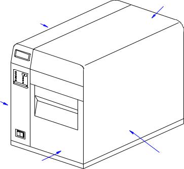
The M84Pro printer was designed for continuous industrial and commercial applications as selfevident with its uncompromising all-metal housing, 203 to 609 dpi resolution, and label width capacity up to 5 inches wide.
This printer uses standard SATO programming language with specific values for print resolutions. These values are specified in “dots” and will vary depending upon the printer resolution and the amount of memory available for label imaging.
The M84Pro was designed to be compatible with preceding M-8400 series printers. The main difference is how it receives the command sequence and how it responds to certain commands. Refer to the Operator and Technical Reference Manuals for additional information.
TOP HOUSING COVER
LEFT HOUSING COVER
PANEL COVER
RIGHT HOUSING COVER
FRONT HOUSING COVER
Figure 1-1, Primary Components
THEORY OF OPERATION
When activated, the media and ribbon (where applicable) are fed in conjunction past the print head by an integrated drive train. The drive train is electric, stepper motor driven, coupled to a gear configuration located on the left side of the printer chassis. Paper guides within the chassis assembly ensure that the media remains properly positioned during the printing process and is fed unimpeded through the front cover. The exhausted ribbon material is rewound onto a take-up core inserted onto drive-train driven spindles.
A series of strategically located sensors send signals to the processing unit. The processing unit in turn sends response signals to the various features based on programmed and received data. Correct signals initiate print head activity.
M84Pro Service Manual |
PN: 9001111A |
Page 1-2 |

Section 1: Introduction
DAUGHTER BOARD
LCD BOARD
INTERFACE BOARD
|
RD |
IEEE1284 |
+ RSBOA |
PANEL BOARD
MAIN CIRCUIT BOARD
BELT CONFIGURATION
POWER BOARD
Figure 1-2, Primary Components
RIBBON SUPPLY SPINDLE
RIBBON REWIND SPINDLE
LCD PANEL 
LABEL ROLL HOLDER
OPERATOR
PANEL
PRINT ASSEMBLY
LABEL HOLD DOWN
PLATEN ROLLER
LOWER FEED ROLLER
STEPPER MOTOR
Figure 1-3, Primary Components
M84Pro Service Manual |
PN: 9001111A |
Page 1-3 |

Section 1: Introduction
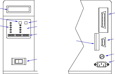
SWITCHES AND INDICATORS
The table below identifies and defines printer switches and indicators for operator interface. The accompanying graphics display their locations and appearance.
|
SWITCHES |
Power Switch |
Two position on/off switch that controls power flow to the system. |
|
|
Line Key |
Toggles the printer between the on-line and off-line modes. When |
|
on-line, the printer is ready to receive data from the host. Acts as a |
|
pause during print by taking the printer off-line. Also used as a scroll- |
|
and-enter interface for printer setup. |
|
|
Feed Key |
Feeds one blank label through the printer when off-line. When the |
|
printer is on-line, another copy of the last label will be printed. Also |
|
used as a scroll-and-enter interface for printer setup. |
|
|
|
INDICATORS |
LCD Display |
Dual line x 16 character display. Used for setting operational param- |
|
eters and displaying error conditions. |
|
|
Power Indicator |
Illuminates when the power switch is activated. |
Label |
Illuminates when the label supply is depleted. |
|
|
Ribbon |
Illuminates when the ribbon supply is depleted. |
Error |
Illuminates when there is a system fault. |
On-Line |
Illuminates when the system is operating. |
|
|
|
DIP SWITCHES |
DSW2 & DSW3 |
Sets operational parameters of printer. |
DSW1 |
Used to configure optional RS232 communication card. |
|
|
CONNECTION PORTS
These ports are externally accessible and permit connection of the accessories and attachments necessary for printer programming and operation. Not listed here, are the connection ports of circuit boards not externally accessible.
|
CONNECTION PORTS |
AC Power Input |
Connector permits 115V, 50/60 Hz supply via supplied cord. |
Interface Port |
Connector for interface harness. Must be connected for the printer to |
|
be operational. Acceptable interface types are: |
|
• RS232C Serial I/F Module, DB-25 |
|
• IEEE1284 Parallel I/F Module, AMP 57-40360 |
|
• Universal Serial Bus Adapter |
|
• Ethernet 10/100 BaseT I/F Module |
|
• RS422/485 I/F Module, DB-9 |
|
|
Ext. Interface Port |
Connector for external control of print cycle. Also supplies power for |
|
optional accessories - AMP 57-60140 |
|
|
Memory Card Slot |
Slot for the insertion of optional PCMCIA Memory Card |
Main Fuse Connection |
For input power protection - type 3A/250V |
M84Pro Service Manual |
PN: 9001111A |
Page 1-4 |
Section 1: Introduction
LCD DISPLAY
LINE KEY
INDICATORS
|
LINE |
FEED |
POWER |
|
|
LABEL |
|
|
RIBBON |
|
OFFSET |
ERROR |
|
PITCH |
ON LINE |
|
DISPLAY |
DSW1 |
DSW2 |
DSW3 |
FEED KEY
POTENTIOMETERS
DIP SWITCHES
MEMORY CARD SLOT
POWER SWITCH
I/F
EXT.
FUSE T3.15A H 250V
100V - 120V
INTERFACE PORT
EXT PORT
MAIN FUSE CONNECTIO
AC POWER INPUT
PANEL COVER |
REAR COVER |
Figure 1-4, Switches, Indicators, and Connection Ports
M84Pro Service Manual |
PN: 9001111A |
Page 1-5 |

TECHNICAL DATA |
2 |
All technical data deemed pertinent has been tabulated below for quick reference. Find the relative section header and then locate the specific type of technical data in th left column.
PHYSICAL CHARACTERISTICS
Width |
10.4 Inches (265 mm) |
|
|
Height |
13.4 Inches (341 mm) |
|
|
Depth |
17.1 Inches (435 mm) |
|
|
Weight |
39.7 Pounds (18.0 mm) |
|
|
POWER
Input Voltage |
115/220 Volts AC +/- 10%, |
50/60 Hertz +/-1% |
|
|
|
Power Consumption |
130 Watt Operating, |
24 Watt Idle |
|
|
|
ENVIRONMENTAL
Operating Temperature |
41° to 104°F (5° to 40°C) |
|
|
Storage Temperature |
23° to 140°F (-5° to 60°C) |
|
|
Storage Humidity |
30 to 90% RH Non-Condensing |
|
|
Operating Humidity |
30 to 80% RH Non-Condensing |
|
|
Electrostatic Discharge |
8kV |
|
|
Method |
Direct or Thermal Transfer |
|
|
|
|
Speed (user selectable) |
M84PRO-2: 2 to 10 Inches Per Second (50 - 250 mm/s) |
|
|
M84PRO-3: 2 to 8 Inches Per Second (50 - 200 mm/s) |
|
|
M84PRO-6: 2 to 6 inches Per Second (50 - 150 mm/s) |
|
|
|
|
Print Module (dot size) |
M84PRO-2: .0049 |
Inches (.125 mm) |
|
M84PRO-3: .0033 |
Inches (.083 mm) |
|
M84PRO-6: .0017 |
Inches (.081 mm) |
|
|
|
Resolution |
M84PRO-2: 203 Dots Per Inch (8 d/mm) |
|
|
M84PRO-3: 305 Dots Per Inch (12 d/mm |
|
|
M84PRO-6: 609 Dots Per Inch (24 d/mm) |
|
Maximum Print Width |
4.1 Inches (104 mm) |
|
|
|
|
Maximum Print Length |
M84PRO-2: 49.2 Inches (1249 mm) |
|
|
M84PRO-3: 32.8 Inches (835 mm) |
|
|
M84PRO-6: 14.0 |
Inches (356 mm) |
|
|
|
M84Pro Service Manual |
PN: 9001111A |
Page 2-1 |
Section 2: Technical Data
MEDIA
Minimum Width |
.87 Inches (22 mm) |
|
|
Minimum Length |
0.24 Inches (6 mm) |
Continuous |
|
Tear-Off |
0.63 Inches (16 mm) |
Cutter |
1.18 Inches (30 mm) |
Dispense |
1.18 Inches (30 mm) |
Maximum Width |
5.0 Inches (125 mm) |
|
|
Type |
Die Cut Labels, Fan-Fold, Tag Stock or Continuous |
|
|
Maximum Caliper |
.008 Inches (.21 mm) |
|
|
Maximum Roll Diameter |
8.6 Inches (220 mm), Wound face inward |
|
|
Minimum Core Diameter |
3 Inches (76.2 mm) |
|
|
RIBBON
Maximum Width |
4.4 Inches (111 mm) |
|
|
Length |
1475 Feet (450 m) |
|
|
Thickness |
4.5 Microns, Wound face inward |
|
|
SENSING
See-Through for labels or tags |
Movable |
|
|
Reflective Eye-Mark |
Movable |
|
|
Continuous Form |
Sensor not used. |
|
|
INTERFACE MODULES
Parallel Port |
IEEE 1284 Standard |
|
|
Serial Port |
RS232C (9600 to 57,6000 dps) Standard |
|
RS422/485 (9600 to 57600 bps) Optional |
|
Ready/Busy or X-On/X-Off Flow Control |
|
Bi-Directional Status |
|
|
Universal Serial Bus |
USB Adapter |
|
|
Ethernet |
10/100 Base T, 802.116 Wireless Wi-Fi |
|
|
Data Transmission |
ASCII Format |
|
|
PROCESSING
CPU |
32 Bit RISC |
|
|
FLash ROM |
2 Mega-Bytes |
|
|
SDRAM |
16 Mega-Bytes |
|
|
Receive Buffer |
2.95 Mega-Bytes |
|
|
Memory Expansion |
See Options and Accessories |
|
|
M84Pro Service Manual |
PN: 9001111A |
Page 2-2 |

Section 2: Technical Data
CHARACTER FONT CAPABILITIES
MATRIX FONTS
U Font |
5 dots W x 9 dots H |
|
|
S Font |
8 dots W x 15 dots H |
|
|
M Font |
13 dots W x 20 dots H |
|
|
XU Font |
5 dots W x 9 dots H (Helvetica) |
|
|
XS Font |
17 dots W x 17 dots H (Univers Condensed Bold) |
|
|
XM Font |
24 dots W x 24 dots H (Univers Condensed Bold) |
|
|
OA Font (OCR-A) |
M84PRO-2: 15 dots W x 22 dots H |
|
M84PRO-3: 22 dots W x 33 dots H |
|
M84PRO-6: 44 dots W x 66 dots H |
OB Font (OCR-B) |
M84PRO-2: 30 dots W x 36 dots H |
|
M84PRO-3: 30 dots W x 36 dots H |
|
M84PRO-6: 60 dots W x 72 dots H |
|
|
AUTO SMOOTHING FONTS |
|
|
|
WB |
18 dots W x 30 dots H |
|
|
WL |
28 dots W x 52 dots H |
|
|
XB |
48 dots W x 48 dots H (Univers Condensed Bold) |
|
|
XL |
48 dots W x 48 dots H (Sans Serif) |
|
|
VECTOR FONT |
|
|
|
|
Proportional or Fixed Spacing |
|
Font Size 50 x 50 dots to 999 x 999 dots |
|
Helvetica, 10 Font Variations |
AGFA RASTER FONTS |
|
|
|
A Font |
CG Times, 8 to 72 pt. |
|
|
B Font |
CG Triumvirate, 8 to 72 pt. |
|
|
DOWNLAODABLE FONTS |
|
|
|
|
Bit Mapped True Type Fonts with Utility Program |
|
|
CHARACTER CONTROL |
|
|
|
|
Expansion up to 12 x in either the X or Y coordinates. |
|
Charcter Pitch Control |
|
Line Space Control |
|
Journal Print facility |
|
0, 90, 180, and 270 Degree Rotation |
|
|
M84Pro Service Manual |
PN 9001111A |
Page 2-3 |

Section 2: Technical Data
BAR CODE CAPABILTIES
Linear Bar Codes |
Bookland (UPC/EAN Supplemental |
|
EAN-8, EAN-13 |
|
CODABAR |
|
Code 39 |
|
Code 93 |
|
Code 128 |
|
Interleaved 2 of 5 |
|
Industrial 2 of 5 |
|
Matrix 2 of 5 |
|
MSI |
|
POSTNET |
|
UCC/EAN-128 |
|
UPC-A and UPC-E |
|
|
Two Dimemsional |
Data Matriix |
|
Maxicode |
|
PDF417 |
|
Micro PDF |
|
Truncated PDF |
|
QR Code |
|
RSS-14 Composite Code |
Ratios |
1:2, 1:3, 2:5, User definable bar widths |
|
|
Bar Height |
4 to 999 dots, User progammable |
|
|
Rotation |
0, 90, 180, and 270 Degrees |
|
|
Sequential Numbering |
Sequential numbering of both numerics and bar codes |
|
|
Custom Characters |
RAM storage for special characters |
|
|
Graphics |
Full dot addressable graphics, SATO Hex/Binary, .BMP or |
|
.PCX formats |
Form Overlay |
Form overlay for high-speed editing of complex formats |
|
|
REGULATORY APPROVALS
Safety |
VCCI (Class B), UL, CUL, CE, FCC (Class B) |
|
|
RFI/EMI |
FCC (Class B) |
|
|
M84Pro Service Manual |
PN: 9001111A |
Page 2-4 |

INTERFACE SPECIFICATIONS |
3 |
This section presents the interface specifications and include detailed information on how to properly interface the printer with the host system.
INTERFACE TYPES
The parallel interface is a high speed, bi-directional interface that conforms to the IEEE1284 specification (ECP mode on some computers). The interface is also compatible with the older Centronics parallel interface standard. If it does not detect the correct IEEE1284 signals in the interface connection, it will automatically operate in the standard Centronics mode which is much slower. To use the IEEE1284 parallel interface to its fullest capability requires that the host also have an IEEE1284 compatible interface and that the two be connected with a cable that meets the IEEE1284 specification. If either of these two are not present, the data rate is reduced.
In order to provide flexibility in communicating with a variety of host computer systems all printers use a Plug-In Interface Module. The IEEE1284 Interface module is shipped with the printer unless another interface type is specified at the time of the order. The other interfaces available is a high speed serial interface, an Ethernet interface, wireless Ethernet, or an optional Universal Serial Bus (USB) Adapter.
The Parallel interface will probably be the most useful in communicating with IBM PCs and compatibles. The RS232C Serial interface allows connectivity to a number of other hosts. The USB interface allows the printer to be connected to a computer that supports peripherals attached to a USB bus. Up to 127 peripherals can be connected to a single USB port.
WARNING: NEVER CONNECT OR DISCONNECT INTERFACE CABLES (OR USE A SWITCH BOX) WITH POWER APPLIED TO EITHER THE HOST OR THE PRINTER. THIS MAY CAUSE DAMAGE TO THE INTERFACE CIRCUITRY IN THE PRINTER/HOST AND IS NOT COVERED BY WARRANTY.
RECEIVE BUFFER
The printer may be configured to receive a data stream from a singular or multiple print jobs. The single job print buffer is generally used by software programs that wish to maintain control of the job print queue so that it can move a high priority job in front of ones of lesser importance. The multiple job buffer, on the other hand prints all jobs in the order they are received by the printer, and the order of printing cannot be changed.
SINGLE JOB BUFFER
The printer receives and prints one job at a time. Each job must not exceed 2.95 MB.
M84Pro Service Manual |
PN: 9001113A |
Page 3-1 |
Section 3: Interface Specifications
MULTIPLE JOB BUFFER
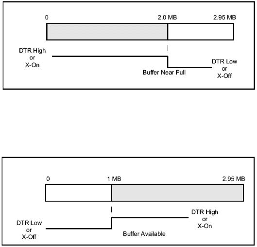
The printer is able to continuously receive print jobs while compiling and printing other jobs at the same time. It acts much like a “print buffer” to maximize the performance of the host and the printer. When using the RS232C Serial interface, the multiple job buffer uses either the Ready/ Busy with DTR (pin 20) or X-On/X-Off flow control protocols. See these sections for more details.
With an empty receiving buffer, the status of DTR is “high” (in X-On status if using X-On/X-Off) meaning the printer is ready to receive data. When the receive buffer is holding 2.0 MB of data (1 MB from being full), DTR will go “low” (an X-Off is sent) indicating the printer can no longer receive data. This condition is called “Buffer Near Full.”
The receiving buffer will not be able to receive more data again until a “Buffer Available” condition occurs. This takes place when the receiving buffer has emptied so that only 1 MB bytes of data are being held (2.0 MB bytes from being full). At this time, DTR will go “high” or an X-On is sent to tell the host that it can again receive data.
All printer error conditions (i.e., label out, ribbon out) will cause the printer to go busy (DTR “low” or X-Off) until the problem is corrected and the printer is placed on-line. The printer will also be busy if taken off-line from the front panel.
M84Pro Service Manual |
PN 9001113A |
Page 3-2 |

Section 3: Interface Specifications
IEEE1284 PARALLEL INTERFACE
The parallel interface for the M-84PRO printers is a Plug-In Interface Module that can be installed by the user. It conforms to the IEEE1284 specification. It will automatically detect the IEEE1284 signals and operate in the high speed mode. If it does not detect the IEEE1284 signals, it will operate in the standard Centronics mode, which is significantly slower. For this reason, an interface cable and host interface conforming to the IEEE1284 specification must be present to fully utilize the speed capabilities. This interface also operates bi-directionally and can report the status of the printer back to the host.
|
SPECIFICATIONS |
Printer Connector |
AMP 57-40360 DDK (or equivalent) |
Cable Connector |
AMP 57-30360 DDK (or equivalent) |
Cable |
IEEE1284 Parallel, 10 ft. (3 m) or less |
Signal Level |
High = +2.4V to +5.0V, Low = 0V to -0.4V |
Data Stream |
<ESC>A . . Job#1 . . <ESC>Z<ESC>A . . Job#n . . <ESC>Z |
NOTE: Pin assignments begin with one (1) in the upper right corner and descend to eighteen (18) in the upper left corner. Pin number nineteen (19) picks up in the lower right corner and descends to thirty-six (36) in the lower left.
IEEE 1284 PARALLEL INTERFACE PIN ASSIGNMENTS
PIN |
SIGNAL |
DIRECTION |
PIN |
SIGNAL |
DIRECTION |
1 |
Strobe |
To Printer |
19 |
Strobe Return |
Reference |
2 |
Data 1 |
To Printer |
20 |
Data 1 Return |
Reference |
3 |
Data 2 |
To Printer |
21 |
Data 2 Return |
Reference |
4 |
Data 3 |
To Printer |
22 |
Data 3 Return |
Reference |
5 |
Data 4 |
To Printer |
23 |
Data 4 Return |
Reference |
6 |
Data 5 |
To Printer |
24 |
Data 5 Return |
Reference |
7 |
Data 6 |
To Printer |
25 |
Data 6 Return |
Reference |
8 |
Data 7 |
To Printer |
26 |
Data 7 Return |
Reference |
9 |
Data 8 |
To Printer |
27 |
Data 8 Return |
Reference |
10 |
ACK |
To Host |
28 |
ACK Return |
Reference |
11 |
Busy |
To Host |
29 |
Busy Return |
Reference |
12 |
Ptr Error |
To Host |
30 |
PE Return |
Reference |
13 |
Select |
To Host |
31 |
INIT |
From Host |
14 |
AutoFD1 |
To Host |
32 |
Fault |
To Host |
15 |
Not Used |
|
33 |
Not Used |
|
16 |
Logic Gnd |
|
34 |
Not Used |
|
17 |
FG |
Frame Gnd |
35 |
Not Used |
|
18 |
+5V (z=24k ohm) |
To Host |
36 |
SelectIn1 |
From Host |
1 Signals required for ieee 1284 mode.
M84Pro Service Manual |
PN: 9001113A |
Page 3-3 |

Section 3: Interface Specifications
RS232 SERIAL INTERFACE
The High Speed Serial Interface is a Plug-In Interface Module that can be installed in the printer by the user.
|
SPECIFICATIONS |
Asynchronous ASCII |
Half-duplex communication |
|
Ready/Busy Hardware Flow Control |
|
Pin 20, DTR Control |
|
Pin 4, RTS Error Condition |
|
X-On/X-Off Software Flow Control |
|
Bi-Directional Communication |
Data Transmission Rate |
9600, 19200, 38400, 57600 bps |
Character Format |
1 Start Bit (fixed) |
|
7 or 8 data bits (selectable) |
|
Odd, Even or No Parity (selectable) |
|
1 or 2 Stop bits (selectable) |
Connector |
DB-25S (Female) |
Cable |
DB-25P (Male), 50 ft. maximum length. |
|
For cable configuration, refer to Cable |
|
Requirements appropriate to the RS232C protocol chosen. |
Signal Levels |
High = +5V to +12V, Low = -5V to -12V |
NOTE: Pin assignments begin with one (1) in the upper right corner and descend to thirteen (13) in the upper left corner. Pin number fourteen (14) picks up in the lower right corner and descends to twenty-five (25) in the lower left.
|
|
RS232C SERIAL INTERFACE SIGNALS |
PIN |
DIRECTION |
SIGNAL DEFINITION |
1 |
Reference |
FG (Frame Ground) |
2 |
To Host |
TD (Transmit Data) - Data from the printer to the host computer. Sends X-On/ |
|
|
X-Off characters or status data (bi-directional protocols). |
3 |
To Printer |
RD (Receive Data) - Data to the printer from the host computer. |
4 |
To Host |
RTS (Request to Send) - Used with Ready/Busy flow control to indicate an |
|
|
error condition. RTS is high and remains high unless the print head is open (in |
|
|
this case, RTS would return to the high state after the print head is closed and |
|
|
the printer is placed back on-line) or an error condition occurs during printing |
|
|
(e.g., ribbon out, label out). |
5 |
To Printer |
CTS (Clear to Send) - When this line is high, the printer assumes that data is |
|
|
ready to be transmitted. The printer will not receive data when this line is low. If |
|
|
this line is not being used, it should be tied high (to pin 4). |
6 |
To Printer |
DSR (Data Set Ready) - When this line is high, the printer will be ready to |
|
|
receive data. This line must be high before data is transmitted. If this line is not |
|
|
being used, it should be tied high (to pin 20). |
7 |
Reference |
SG (Signal Ground) |
M84Pro Service Manual |
PN 9001113A |
Page 3-4 |

Section 3: Interface Specifications
|
|
RS232C SERIAL INTERFACE SIGNALS |
PIN |
DIRECTION |
SIGNAL DEFINITION |
20 |
To Host |
DTR (Data Terminally Ready) - This signal applies to Ready/Busy flow control. |
|
|
The printer is ready to receive data when this pin is high. It goes low when the |
|
|
printer is off-line, either manually or due to an error condition, and while |
|
|
printing in the single job buffer mode. It will also go low when the data in the |
|
|
buffer reaches the buffer near full level. |
CABLE REQUIREMENTS
DB9 |
DB25 |
HOST |
INTERCONNECTION |
DB25 |
PRINTER |
|
1 |
1 |
FG |
< |
---------------- |
1 |
FG (Frame Ground) |
2 |
3 |
RD |
---------------- |
> |
2 |
TD (Transmit Data) |
3 |
2 |
TD |
<--------------- |
> |
3 |
RD (Receive Data) |
8 |
5 |
CTS |
-------- |
I |
4 |
RTS (Request to Send) |
|
|
|
|
I |
|
|
7 |
4 |
RTS |
-------- |
5 |
CTS (Clear to Send) |
|
4 |
20 |
DTR |
< -------- |
I |
6 |
DSR (Data Set Ready) |
6 |
6 |
DSR* |
|
20 |
DTR (Data Terminal Ready) |
|
5 |
7 |
SG |
<--------------- |
> |
7 |
SG (Signal Ground) |
* This connection at the host side of the interface would depend upon the pin that is being used as the Ready/Busy signal by the driving software. Typically, on a PC, it would be either CTS (pin5) or DSR (pin 6) on a DB-25 connector.
READY/BUSY FLOW CONTROL
Ready/Busy is the hardware flow control method for the serial interface on the M-84PRO printers. By raising/lowering the voltage level on Pin 20 of the RS232C port, the printer notifies the host when it is ready to receive data. Pin 4 (RTS) and pin 20 (DTR) are the important signals on the printer for this method of flow control. The host must be capable of supporting this flow control method for it to function properly.
X-ON/X-OFF FLOW CONTROL
X-On/X-Off flow control is used whenever hardware (Ready/Busy) flow control is not available or desirable. Instead of a voltage going high/low at pin 20, control characters representing ìPrinter Readyî (X-On =11 hexadecimal) or “Printer Busy” (X-Off = 13 hexadecimal) are transmitted by the printer on pin 2 (Transmit Data) to the host. In order for this method of flow control to function correctly, the host must be capable of supporting it. X-On/X-Off operates in a manner similar to the function of pin 20 (DTR) as previously explained. When the printer is first powered on it sends an X-Off when the “Buffer Near Full” level is reached and a X-On when the data level of the buffer drops below the “Buffer Available” mark. When the printer is taken off-line manually, it transmits an X-Off indicating it cannot accept data. When it is placed back on line manually, it sends an X- On, indicating it is again available for receipt of data. If an error occurs during printing (paper out, ribbon out), the printer sends an X-Off as soon as an error condition is detected. When the error is cleared and the printer is placed back on-line, it transmits an X-On indicating it is again ready to accept data. Upon power up if no error conditions are present, the printer will continually send X-On characters at five millisecond intervals until it receives a transmission from the host.
M84Pro Service Manual |
PN: 9001113A |
Page 3-5 |
Section 3: Interface Specifications
DATA STREAMS
The data streams for X-On/X-Off and Ready/Busy flow control are constructed in the same way as they are for Ready/Busy flow control (<ESC>A . . Job#1 . . <ESC>Z<ESC>A . . Job#n . . <ESC>Z). An example of this would be: <ESC>A . . Job#1 . . <ESC>Z. All characters are in ASCII.
UNIVERSAL SERIAL BUS (USB) ADAPTER
The Universal Serial Bus (USB) interface is a Plug-In Interface Module that can be installed by the user. It requires a driver (shipped with each printer that has the interface installed) that must be loaded on your PC and the PC must be configured to support USB peripherals using Windows 98 or above. Details for loading the USB driver are contained in the USB Interface Manual that is shipped with each printer with a USB Optional interface installed. Up to 127 devices may be connected to a USB port using powered hubs.
|
SPECIFICATIONS |
Printer Connector |
USB Type B Plug |
Cable |
10 feet (3 m) maximum |
Host |
Windows 98 or above with USB Port |
Power Supply |
BUS Power through cable |
Power Consumption |
+5 V at 80 ma |
LOCAL AREA NETWORK (LAN) INTERFACE
A Local Area Network (LAN) interface is an optional Plug-In Interface Module that can be installed by the user. It requires a driver shipped with each printer that has the interface installed. The driver that must be loaded on your PC and the PC must be configured to run one of the supported network protocols using a 10/100BaseT LAN connection. Details for loading the LAN driver are contained in the LAN Interface Manual that is shipped with each printer with a LAN Optional interface installed.
|
SPECIFICATIONS |
Connector |
RJ-45 Receptacle |
Cable |
10/100BaseT Category 5 |
Power Supply |
Powered from printer |
BI-DIRECTIONAL COMMUNICATIONS
This is a two-way communications protocol between the host computer and the printer, thus enabling the host to check printer status. When Bi-Com 4 communications is selected, there is no busy signal from the printer. The host must request the complete status from the printer, including ready/busy. The host may request status in two different ways.
ENQUIRE/ACK/NAK
In the Bi-Com 4 mode, the host transmits an ENQ (05 hexadecimal) to the printer and the printer will respond with its status within five milliseconds. If printing, it will respond upon finishing the current label, then resume printing. In order for this protocol to work properly with an RS232C
M84Pro Service Manual |
PN 9001113A |
Page 3-6 |
Section 3: Interface Specifications
Optional Interface, pin 6 (DTR) and pin 5 (CTS) must be held high by the host. One way to ensure these pins are always in the correct state is to tie pin 20 (DTR) to pin 6 (DSR) and pin 4 (RTS) to pin 5 (CTS) at the printer end of the cable.
ENQUIRE (ENQ)
Upon receipt of an ENQ command, the printer responds with 25 bytes of status information bounded by an STX/ETX pair. The Bi-Com protocol works only in the multiple job buffer mode. The status information is defined as follows:
<STX>{ 2 Byte ID}{1 Status Byte}{6 Byte Label Remaining}{16 Byte Job Name}<ETX>
|
STREAM IDENTIFICATION |
|
ID |
|
Is a two byte number identifying the current print job ID. The |
|
|
print job ID is defined using the <ESC>ID Job ID command |
|
|
transmitted with the print job (see Job ID Store in the |
|
|
command listing for more information on how to use this |
|
|
command). The range is from 00 to 99. |
Status |
|
A single byte defining the current status of the printer (see the |
|
|
Status Byte Definition table). |
Label Remaining |
|
Six bytes defining the number of labels remaining in the current |
|
|
print job. The range is from 000000 to 999999 labels. |
Job Name |
|
16 bytes of ASCII characters identifying the name assigned |
|
|
to the job by the <ESC>WK Job Name command. If the Job |
|
|
Name is less than 16 characters, the field will be padded |
|
|
with leading zeroes. |
|
|
If an ENQ is received after the print job specified in the ID |
|
|
bytes has been completed, or there is no data in the buffer, |
|
|
the printer will respond with two “space” characters (20 |
|
|
hexadecimal) for the ID number, six “zero” characters (30 |
|
|
hexadecimal) in the Remaining Labels bytes and the 16 |
|
|
byte Job Name. |
CANCEL (CAN)
If a CAN (18 hexadecimal) command is received, it will stop the print job and clear all data from the receive and print buffers. A delay of five milliseconds or more is required before any new data can be downloaded. The CAN command is effective immediately upon receipt, even if the printer is off-line or in an error condition. The printer will return an ACK (06 hexadecimal) if there is no printer error condition and a NAK (15 hexadecimal) if an error condition exists.
PRINT JOB
Upon receipt of a valid print job (<ESC>A . . . <ESC>Z), an ACK (06 hexadecimal) will be returned by the printer if there are no errors and a NAK (16 hexadecimal) if a printer error exists.
M84Pro Service Manual |
PN: 9001113A |
Page 3-7 |
Section 3: Interface Specifications
PRINT STOP (DLE)
If a DLE (10 hexadecimal) is received by the printer, the print process is stopped and an ACK (06 hexadecimal) is returned if there are no errors and a NAK (16 hexadecimal) if a printer error exists.
PRINT START (DC1)
If the printer has been stopped by receipt of a DLE (10 hexadecimal) command, it can be restarted by sending a DC1 (hexadecimal 11) command. Upon receipt of this command an ACK (06 hexadecimal) is returned if there are no errors and a NAK (16 hexadecimal) if a printer error exists.
Note: To provide compatibility with older SATO printers, the RS232C interface can be configured to use an earlier Bi-Com 3 ENQ/ACK/NAK protocol selected via DSW2-8 and DSW1-7/8 (on the RS232 Interface module).The earlier protocol did not have provisions for the Job Name and did not respond to the DLE or DCI commands. Also, there are additional Response Codes in the Status Byte Definition. It is recommended that you use the current protocol rather than the earlier version unless it is necessary for compatibility with existing software.
M84Pro Service Manual |
PN 9001113A |
Page 3-8 |

ACCESSORIES INSTALLATION |
4 |
The following procedures provide in-depth instructions on the installation of all optional accessories. Each accessory is a purchase option that may not apply to your setup. Refer to the list below to determine if any are applicable and their installation is required. If not, disregard this section of the manual and proceed to the next.
Label Cutter Kit |
Label dispenser |
PCMCIA Memory Expansion |
Flash Memory Expansion |
Real Time Clock |
Interface Module Upgrade |
LABEL CUTTER INSTALLATION
This procedure only covers the physical installation of cutter assembly hardware. Refer to other procedures for configuration, etc.
NOTE: Additional relative information may also be found in Figure 10-5,
Accessories & Sensors Location; Figure 10-6, Print Position Reference
Diagram; and Figures 10-12 through 10-15, Operation & Timing Charts of the
Diagrams & Schematics section.
1Switch off the printer and disconnect the power supply cord.
2Open/remove the top, right, and left housing covers.
NOTE: Figures 10-1, 10-2, and 10-3 in the Diagrams & Schematics section provide guidance on housing cover, media, and ribbon removal respectively.
3Remove the ribbon and label stock if applicable and leave the print head open.
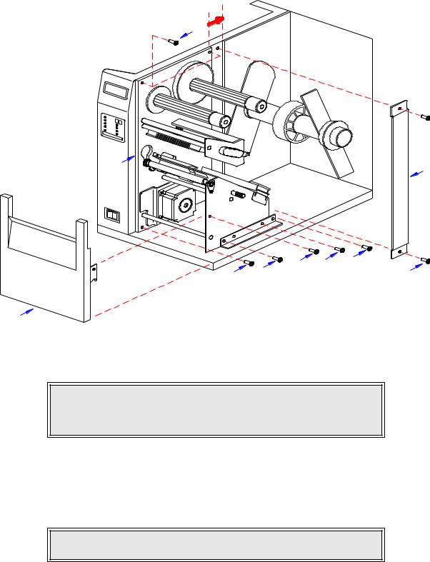
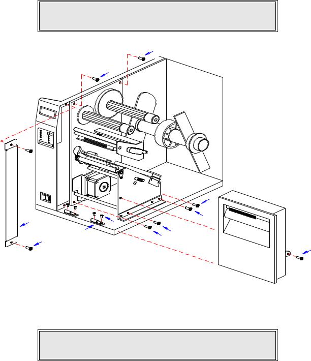
4Remove screw (1, Figure 4-1a) securing front cover (2) to the printer frame. Lift away front cover (2).
NOTE: The screw is accessible at the rear of the cover on the right side.
Manipulate the cover upward and outward to remove.
5Remove two screws (3) to detach spacer panel (4). Lift away spacer panel (4).
6Remove four screws (5) from back panel (6) and two screws (7) from side frame bracket (8) to release the entire print mechanism.
NOTE: The print mechanism will be all that is stainless steel or aluminum. The print mechanism back plate is vertically arranged and reaches from the very top down to the base.
M84Pro Service Manual |
PN: 9001111A |
Page 4-1 |
Section 4: Accessories Installation
5
6 |
4 |
|
|
1 |
7 |
5 |
5 |
7 |
|
3 |
|
|
2
Figure 4-1a, Label Cutter Installation
7 Slide entire print mechanism fully toward the rear.
CAUTION: ENSURE WIRING HARNESSES ARE NOT PINCHED WHEN
ADJUSTING THE PRINT MECHANISM. THE PRINT MECHANISM WHEN
ADJUSTED, WILL COVER THE VOID LEFT BY THE REMOVAL OF THE
SPACER PANEL.
8Reapply two screws (7) to side frame bracket (8) and four screws (5) to back panel (6) to secure print mechanism.
9Attach two hinge halves (9, Figure 4-1b) to the front base of the printer using two screws (10) for each.
NOTE: Before tightening the hinge screws, pull the hinges forward to align them.
10Install spacer panel (4) into the void left in front of print mechanism and secure using two screws (3).
M84Pro Service Manual |
PN 9001111A |
Page 4-2 |
Section 4: Accessories Installation
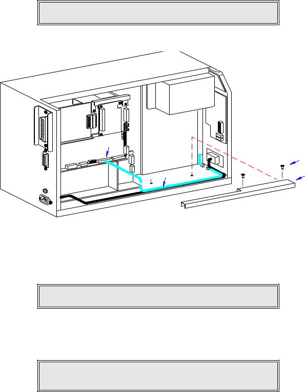
11Route the single connector end of cutter wiring harness (11, Figure 4-1c) through the printer side wall from the electric side to the mechanical side.
CAUTION: WHEN ROUTING THE WIRING HARNESS, ENSURE THAT IS
IS ROUTED IN A MANNER SO AS TO PREVENT PINCHING OR
INTANGLEMENTS.
5
5
5
4 |
7 |
|
10 |
||
|
9 |
7 |
3 |
5 |
|
1
Figure 4-1b, Label Cutter Installation
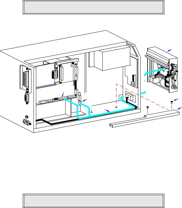
12Connect wiring harness (11) to cutter assembly (12), main circuit board board (13), and power board (14).
NOTE: There is one small connector on the wiring harness that will remain unconnected for cutter installation. Ensure the connectors are properly oriented when mating. Equipment damage may occur otherwise.
13Attach cutter assembly (11) to the printer base by connecting their respective hinge halves.
14Remove two screws (15) securing cable shield (16).
15Encase cutter wiring harness (11) with the power cable in cable shield (16) and secure using two screws (15).
M84Pro Service Manual |
PN: 9001111A |
Page 4-3 |
Section 4: Accessories Installation
16Place DSW3-1 in the up position and the DSW3-2 in the down position.
17Load the printer with ribbon and media stock and close/install all housing covers.
NOTE: Refer to Figures 10-1, 10-2, and 10-3 in the Diagrams & Schematics section for housing cover, media, and ribbon installation respectively.
18 Restore power and test cycle.
12
LCD
|
|
|
|
|
|
ER |
|
|
|
|
|
HT |
|
|
|
|
UG |
|
||
|
|
CE |
DA |
|
RD |
|
|
|
|
A |
|
||
|
FA |
BO |
|
|
||
ER |
|
|
|
|
|
|
INT |
|
D |
|
|
|
|
|
AR |
|
|
|
|
|
BO |
|
|
|
|
|
|
PANEL BOARD
|
|
|
|
|
N |
|
|
|
|
|
|
|
|
|
|
|
|
|
|
|
|
|
|
TIO |
|
|
|
|
|
|
|
|
RA |
|
|
|
|
|
|
|
|
GU |
|
|
|
|
|
|
|
|
NFI |
|
|
|
|
|
|
|
|
LTCO |
|
|
|
|
|
|
|
|
|
BE |
|
|
|
|
|
|
|
|
|
|
|
|
|
|
RD |
|
|
|
OA |
||
|
|
ITB |
|
|
|
|
CU |
|
|
|
|
INCIR |
|
|
|
|
|
MA |
|
|
|
|
|
|
|
|
|
|
D |
|
|
|
|
AR |
|
|
|
RBO |
|
||
|
WE |
|
|
|
|
|
PO |
|
|
|
|
13
14 |
15 |
16
11
Figure 4-1c, Label Cutter Installation
DISPENSER INSTALLATION
Installation of the optional label dispenser into the printer adds the convenience of automatic label dispensing. Each label is printed, then peeled from the backing paper and presented at the front of the printer for removal by the operator. A photo-electric sensor detects the presence of a completed label and signals the printer to automatically backfeed the label stock for correct alignment of the next print cycle.
NOTE: Refer to Figure 10-5, Accessories & Sensors Location in the
Diagrams & Schematics section if assistance is needed.
1 Switch off the printer and disconnect the power supply cord. 2 Open/remove the top, right, and left housing covers.
M84Pro Service Manual |
PN 9001111A |
Page 4-4 |
Section 4: Accessories Installation
NOTE: Figures 10-1, 10-2, and 10-3 in the Diagrams & Schematics section provide guidance on housing cover, media, and ribbon removal respectively.
3Remove the ribbon and label stock if applicable and leave the print head open.
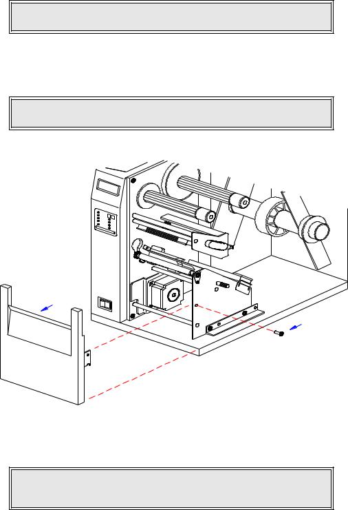
4Remove screw (1, Figure 4-2a) securing front cover (2) to the printer frame. Lift away front cover (2).
NOTE: The screws are accessible at the rear of the cover on the right side.
Manipulate the cover upward and outward to remove.
2
1
Figure 4-2a, Dispenser Installation
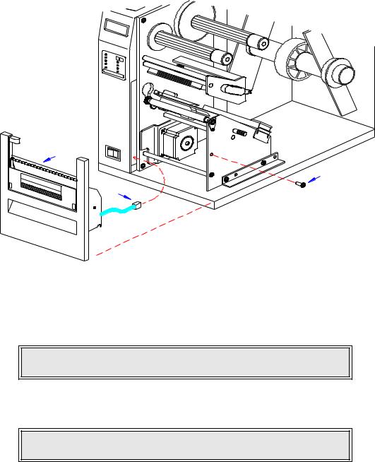
5 Route dispenser wiring harness (3) through the slot in the printer side wall.
CAUTION: WHEN ROUTING THE WIRING HARNESS, ENSURE THAT IIS
ROUTED IN A MANNER SO AS TO PREVENT PINCHING OR
INTANGLEMENTS.
M84Pro Service Manual |
PN: 9001111A |
Page 4-5 |
Section 4: Accessories Installation
4
1
3
Figure 4-2b, Dispenser Installation
6Insert dispenser (4, Figure 4-2b) in place of removed front cover (2) and secure using screw (1).
NOTE: Dispenser installation will only require a single screw. Discard the remaining screw from front cover removal.
7Connect dispenser wiring harness (3, Figure 4-2c) with free end of wiring harness connected to CN10 port (5) of main circuit board.
CAUTION: ENSURE THE CONNECTORS ARE PROPERLY ORIENTED
WHEN MATING. EQUIPMENT DAMAGE MAY OCCUR OTHERWISE.
8Remove two screws (6) securing cable shield (7).
9Encase cutter wiring harness (3) along with the power cable, in cable shield (7) and secure using two screws (6).
10Place the DSW3-1 and the DSW3-2 dip switches in the up position.
11 Load the printer with ribbon and media stock and close/install all housing covers.
M84Pro Service Manual |
PN 9001111A |
Page 4-6 |
Section 4: Accessories Installation
NOTE: Figures 10-1, 10-2, and 10-3 in the Diagrams & Schematics section provide guidance on housing cover, media, and ribbon installation.
12 Restore power and test cycle.
|
|
|
TER |
|
|
|
GH |
|
|
CE |
DAU D |
|
|
AR |
|
RFA |
BO |
||
INTE |
|
D |
|
|
AR |
|
|
BO |
|
|
|
L |
|
C |
|
D |
|
P |
|
A |
|
N |
|
EL B |
|
OA |
|
|
R |
|
D |
|
|
|
|
|
N |
|
|
|
|
ATIO |
|
|
|
|
UR |
|
|
|
|
FIG |
|
|
|
|
ON |
|
|
|
|
TC |
|
|
|
|
|
BEL |
|
|
|
|
|
5
|
|
|
|
D |
|
|
|
AR |
|
|
|
UITBO |
|
|
|
IRC |
|
|
|
NC |
|
|
|
|
MAI |
|
|
|
|
6
3 |
7 |
|
D |
AR |
|
WERBO |
|
PO |
|
Figure 4-2c, Dispenser Installation
FLASH MEMORY INSTALLATION
1Switch off the printer and disconnect the power supply cord.
2Open/remove the top, right, and left housing covers.
NOTE: Figure 10-1 in the Diagrams & Schematics section provides guidance on housing cover removal.
3Remove three screws (1, Figure 4-3) securing daughter board (2) to main circuit board (3).
4Disconnect daughter board (2) from circuit board (3).
5Insert flash card (4) into its reserved brackets on main circuit board (3).
NOTE: The flash card will properly insert into the connector bracket in a single orientation. Ensure that the contactor side is goes first then press inward to index the notched areas.
M84Pro Service Manual |
PN: 9001111A |
Page 4-7 |

Section 4: Accessories Installation
3
|
RD |
IEEE1284 |
+RS BOA |
|
1
4 |
2 |
|
5
Figure 4-3, Flash Card Installation
6Apply and connect daughter board (2) to main circuit board (3) and secure using three screws (1).
7Ensure power supply wiring harness (5) is fully connected to daughter board (2).
8Factory Reset as directed in the Factory Reset section of this manual.
9Restore power, test cycle, and replace covers.
NOTE: Figure 10-1 in the Diagrams & Schematics section provides guidance on housing cover installation.
PCMCIA MEMORY EXPANSION INSTALLATION
1Switch off the printer and disconnect the power supply cord.
2Open/remove the top, right, and left housing covers.
NOTE: Figure 10-1 in the Diagrams & Schematics section provides guidance on housing cover removal.
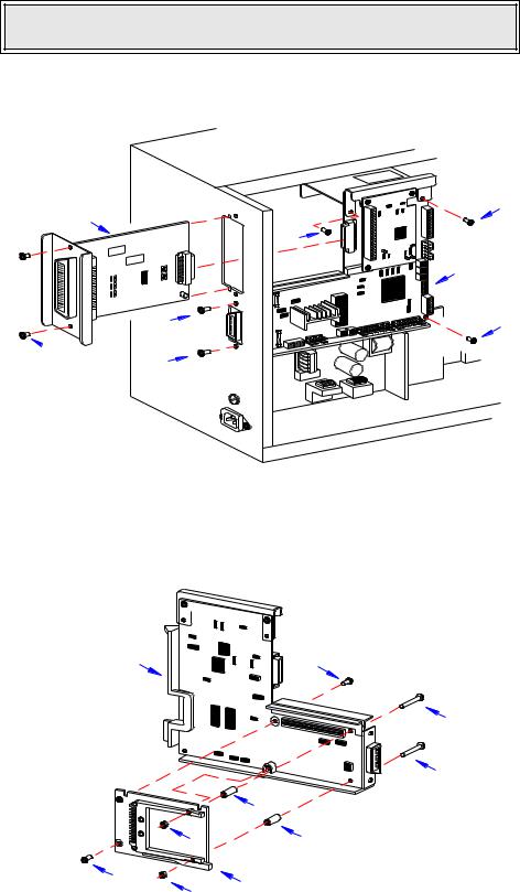
3Remove two screws (1, Figure 4-4a) securing interface board (2) to the rear printer housing.
4Withdraw interface board (2) from printer.
5Remove two screws (3) securing main circuit board (4) to the rear printer housing.
6Remove three screws (5) securing main circuit board (4) to the printer frame.
7Manipulate main circuit board (4) from printer.
M84Pro Service Manual |
PN 9001111A |
Page 4-8 |
Section 4: Accessories Installation
NOTE: It is advised that all wiring harnesses remain connected during expansion board instalation to prevent the possibility of incorrect connections.
2
IEEE1284+ RSBOARD
3
 1
1
3
5
5
4
5
Figure 4-4a, Memory Expansion
8 Insert two long screws (6, Figure 4-4b) into main circuit board (4) from the front.
4 |
10 |
6
6
7
9 |
7 |
10 |
8 |
|
9 |
Figure 4-4b, Memory Expansion
M84Pro Service Manual |
PN: 9001111A |
Page 4-9 |
Loading...