


 Loading...
LM Basic (408e/412e)
OPERATOR’S MANUAL

SATO ASIA PACIFIC PTE. LTD.
438A ALEXANDRA ROAD
#05-01/04 ALEXANDRA TECHNOPARK
SINGAPORE 119967
Tel: (65) 6271 5300
Fax: (65) 6273 6011
Sales Hotline: (65) 6276 2722 Service Hotline: (65) 6273 6455 Email: sales@satoasiapacific.com Website: www.satoworldwide.com
Be sure to ask your dealer about our maintenance contracts to ensure peace of mind during your usage of SATO products
©Copyright 1994 – 2006 SATO International
Warning: This equipment complies with the requirements in Part 15 of FCC rules for a Class A computing device. Operation of this equipment in a residential area may cause
unacceptable interference to radio and TV reception requiring the operator to take whatever steps are necessary to correct the interference.
All rights reserved. No part of this document may be reproduced or issued to third parties in any form whatsoever without the express permission of SATO. The materials in this document are provided for general information and are subject to change without notice. SATO assumes no responsibilities for any errors that may appear.
Version: SI-LM4xxe-01rA-16-01-OM
TABLE OF CONTENTS
1. OVERVIEW
1.1 General Specifications ........................................................................................ |
1-2 |
2. INSTALLATION
Safety Precautions..................................................................................................... |
2-2 |
|
2.1 |
Unpacking............................................................................................................. |
2-4 |
2.1.1 Included Accessories ....................................................................................... |
2-5 |
|
2.1.2 Parts Identification............................................................................................ |
2-6 |
|
2.2 |
Loading the Carbon Ribbon................................................................................ |
2-8 |
2.3 |
Loading Labels..................................................................................................... |
2-9 |
2.3.1 Loading Roll Paper ........................................................................................ |
2-10 |
|
2.3.2 Loading Fanfold Paper .................................................................................. |
2-11 |
|
2.3.3 Adjusting the Paper Sensor ............................................................................. |
2-12 |
|
2.4 |
Replacing the Print Head .................................................................................... |
2-13 |
3. CONFIGURATION AND OPERATION
3.1 Operating Modes.................................................................................................. |
3-1 |
3.2 The Operation Panel ............................................................................................ |
3-2 |
3.3 Accessing the Various PRINTER MODES ......................................................... |
3-3 |
3.3.2 Overview of LCD Menu Options In Various Modes ....................................... |
3-5 |
3.4 NORMAL Modes................................................................................................... |
3-8 |
3.4.1 Online ............................................................................................................. |
3-8 |
3.4.2 Offline .............................................................................................................. |
3-8 |
3.4.3 Print Darkness ................................................................................................. |
3-8 |
3.4.4 Print Speed ...................................................................................................... |
3-9 |
3.4.4 Pitch Offset ...................................................................................................... |
3-9 |
3.4.5 Cancel Print Job .............................................................................................. |
3-9 |
3.5 ADVANCED Mode ................................................................................................ |
3-10 |
3.5.1 Advanced ....................................................................................................... |
3-10 |
3.5.2 Darkness Range ............................................................................................. |
3-10 |
3.5.3 Zero Slash ....................................................................................................... |
3-10 |
3.5.4 Auto Online ...................................................................................................... |
3-10 |
3.5.5 Print Offset ....................................................................................................... |
3-10 |
3.5 Advanced Mode (cont’d) ..................................................................................... |
3-11 |
3.5.6 Set Calendar .................................................................................................... |
3-11 |
3.6 SERVICE Mode..................................................................................................... |
3-12 |
3.6.1 Service ........................................................................................................... |
3-12 |
3.6.2 Slice Level ...................................................................................................... |
3-12 |
3.6.3 Auto Line Feed ................................................................................................ |
3-12 |
3.6.4 Feed On Error .................................................................................................. |
3-12 |
3.6.5 Reprint W/Feed ................................................................................................ |
3-12 |
3.6.6 Forward/Backfeed Amount ............................................................................. |
3-13 |
1
3.6.7 Euro Code ....................................................................................................... |
3-13 |
3.6.8 Select Language .............................................................................................. |
3-13 |
3.6.9 Command or LCD Priority ................................................................................ |
3-13 |
3.6.10 Ignore CAN/DLE ............................................................................................ |
3-13 |
3.6.11 Ribbon Near End On/Off ................................................................................ |
3-14 |
3.6.12 IEEE1284 ACK Signal ................................................................................... |
3-14 |
3.6.13 Backfeed Speed ............................................................................................ |
3-14 |
3.7 COUNTERS Mode ................................................................................................ |
3-15 |
3.7.1 Counters ........................................................................................................ |
3-15 |
3.7.2 Counter Select ................................................................................................ |
3-15 |
3.7.3 Show Head Counter ........................................................................................ |
3-15 |
3.7.4 Clear Head Counter ......................................................................................... |
3-15 |
3.7.5 Show Life Counter ........................................................................................... |
3-15 |
3.8 MOVE Mode .......................................................................................................... |
3-16 |
3.8.1 Movements of Labels ....................................................................................... |
3-16 |
3.8.2 Move Mode ..................................................................................................... |
3-16 |
3.8.3 Pitch Sensor .................................................................................................... |
3-16 |
3.9 TEST PRINT Mode................................................................................................ |
3-17 |
3.9.1 Select Test Print .............................................................................................. |
3-17 |
3.9.2 Test Print Size ................................................................................................ |
3-17 |
3.9.3 Print Size ......................................................................................................... |
3-17 |
3.9.3 Start/Stop Test Print ........................................................................................ |
3-17 |
3.10 DEFAULT SETTING Mode ................................................................................. |
3-18 |
3.10.1 Resetting the Printer ...................................................................................... |
3-18 |
3.10.2 Reset Completed ......................................................................................... |
3-18 |
3.11 Protocol Storing................................................................................................. |
3-19 |
3.11.1 Protocol Download ......................................................................................... |
3-19 |
3.11.2 Loading Completed ....................................................................................... |
3-19 |
3.11.3 Initialization of Protocol Code ........................................................................ |
3-19 |
3.12 MAINTENANCE Mode ........................................................................................ |
3-20 |
3.12.1 Factory or All Clear Mode ............................................................................ |
3-20 |
3.12.2 Factory Mode ................................................................................................ |
3-20 |
3.12.3 Test-Print Width ............................................................................................ |
3-20 |
3.12.4 Start/Stop Test Print ...................................................................................... |
3-20 |
3.12.5 All Clear Mode ............................................................................................. |
3-21 |
3.12.6 Counter/EEPROM clear ................................................................................. |
3-21 |
3.12.7 Clear Confirmation ......................................................................................... |
3-21 |
3.13 HEX DUMP Mode................................................................................................ |
3-22 |
3.13.1 LCD Status .................................................................................................. |
3-22 |
3.13.2 Hex Dump Mode in buffer .............................................................................. |
3-22 |
3.14 DOWNLOAD Mode ............................................................................................. |
3-23 |
3.14.1 LCD Status .................................................................................................. |
3-23 |
3.15 BOOT DOWNLOAD Mode.................................................................................. |
3-24 |
3.15.1 LCD Status .................................................................................................. |
3-24 |
2
TABLE OF CONTENTS (CON’TD)
4. CLEANING AND MAINTENANCE
4.1 |
Introduction .......................................................................................................... |
4-1 |
4.2 |
Cleaning The Print Head, Platen and Rollers .................................................... |
4-1 |
4.3 |
How To Clean The Printer (With A Cleaning Set).............................................. |
4-2 |
4.4 |
How To Clean The Printer (Cleaning Sheet)...................................................... |
4-3 |
4.5 |
Adjusting Print Quality ........................................................................................ |
4-4 |
4.5.1 Adjusting Print Darkness ................................................................................. |
4-4 |
|
4.5.2 Adjusting Print Speed ...................................................................................... |
4-5 |
|
4.6 |
Replacing A Blown Fuse ..................................................................................... |
4-5 |
5. INTERFACE SPECIFICATIONS
5.1 |
Interface types...................................................................................................... |
5-1 |
|
5.2 |
Interface Card DIP SWITCH Settings (RS-232C) ............................................... |
5-2 |
|
5.3 |
Interface Card DIP SWITCH Settings (LAN)....................................................... |
5-3 |
|
5.4 |
Interface Card DIP SWITCH Settings (Wireless LAN)....................................... |
5-3 |
|
5.5 |
External Signal Interface ..................................................................................... |
5-4 |
|
5.6 |
Serial Interface Specifications (RS-232C).......................................................... |
5-4 |
|
5.7 READY/BUSY ....................................................................................................... |
5-5 |
||
5.8 |
Single Job Buffer ................................................................................................. |
5-6 |
|
5.9 |
Multi Job Buffer.................................................................................................... |
5-7 |
|
5.10 |
X-ON/X-OFF ........................................................................................................ |
5-7 |
|
5.11 |
Single Job Buffer ............................................................................................... |
5-9 |
|
5.12 |
Multi Job Buffer.................................................................................................. |
5-10 |
|
5.13 |
IEEE 1284 Interface............................................................................................ |
5-11 |
|
5.13 |
Interface Signals ................................................................................................ |
5-13 |
|
5.14 |
Single Job Buffer ............................................................................................... |
5-14 |
|
5.15 |
Multi Job Buffer.................................................................................................. |
5-16 |
|
6. TROUBLESHOOTING
6.1 |
Initial Checklist..................................................................................................... |
6-1 |
6.2 |
Using the RS232C (SERIAL) Interface ............................................................... |
6-2 |
6.3 |
Understanding the LCD Error Messages........................................................... |
6-3 |
6.4 |
Troubleshooting Guide ....................................................................................... |
6-4 |
3
TABLE OF CONTENTS (CON’TD)
7. OPTIONAL ACCESSORIES
7.1 |
Introduction .......................................................................................................... |
7-1 |
7.2 |
Available Interface Boards.................................................................................. |
7-1 |
7.3 |
Optional Accessories: Interface boards ............................................................ |
7-2 |
7.4 |
Optional Accessories: Others ............................................................................ |
7-4 |
4

Section 1: Introduction
1
OVERVIEW
Thank you for your investment in this SATO printer product.
This Operator’s Manual contains basic information about the installation, setup, configuration, operation and maintenance of the printer.
A total of seven topics are covered herein, and they are organized as follows:
Section 1: Overview
Section 2: Installation
Section 3: Configuration and Operation
Section 4: Cleaning and Maintenance
Section 5: Interface Specifications
Section 6: Troubleshooting
Section 7: Optional Accessories
It is recommended that you become familiar with each section before installing and maintaining the printer. Refer to the Table Of Contents at the front of this manual to search for the relevant information needed. All page numbers in this manual consist of a section number followed by the page number within the stated section.
For specialized programming, refer to the separate Programming Manual available from your authorized SATO dealer.
LM Basic 408e/412e Operator’s Manual |
Page 1-1 |
Section 1: Introduction
1.1 GENERAL SPECIFICATIONS
The SATO LM 408e and 412e are dual-use (Thermal Transfer and Direct Thermal) high performance labeling solutions designed for logistics and manufacturing sectors. Based mechanically on the field-proven CL ‘enhance’ series, the LM408e and LM412e promise reliable operation and consistent performance at a reasonable cost.
Key features of the two models in the LM Basic series are:
•Low cost 4-inch printer for Logistics and Warehousing
•Backlit two-line 16-character alphanumeric LCD panel
•Clear printing at a fixed resolution of 203dpi/305dpi
•Support for a wide range of I/O interfaces
•Supports SATO Barcode Programming Language for enhanced customizability
•Field-proven label and ribbon path from the acclaimed CL ‘enhance’ series
The two models support all popular barcodes, including 2-D codes. Seven human-read- able fonts and two fast and efficient vector fonts, are resident in memory, providing literally thousands of combinations of type styles and sizes.
|
Key Feature |
LM408e and LM412e |
|
|
|
|
Print resolution |
203dpi/305dpi |
|
|
|
|
Print method |
Thermal Transfer and Direct Thermal |
|
|
|
|
Label sizes supported |
LM408e: 4 inches (W) by 7 inches |
|
(using default internal |
LM412e: 4 inches (W) by 7 inches |
|
memory) |
|
|
|
|
|
Label sizes supported |
LM408e: 4 inches (W) by 49.2 inches at 203 dpi |
|
|
LM412e: 4 inches (W) by 32.7 inches at 305 dpi |
|
|
|
|
Interfaces available |
One of the following interfaces installable upon purchase: |
|
|
High speed RS-232C (25-pin), LAN, USB, IEEE 1284/parallel |
|
|
|
Page 1-2 |
LM Basic 408e/412e Operator’s Manual |
|
|
|
|
|
Section 1: Introduction |
1.1 GENERAL SPECIFICATIONS (CONT’D) |
|
|
|||
|
|
|
|
|
|
|
|
|
|
|
|
|
|
Specification |
Model LM408e |
|
Model LM412e |
|
|
|
|
|
|
|
|
Electrical Characteristics |
|
|
|
|
|
|
|
|
|
|
|
Print method |
Thermal transfer or direct thermal |
||
|
|
|
|
|
|
|
|
Head density |
8 dots/ mm (203 dpi) |
|
12 dots/ mm (305 dpi) |
|
|
|
|
|
|
|
|
Printable Area |
W104 mm x pitch 1249 mm (203dpi) |
||
|
|
|
|
||
|
|
|
(No printing within 3 mm from the inner edge) |
||
|
|
|
|
|
|
|
|
Print speed |
2 to 6 inches/sec @203dpi |
(adjustable in 1-inch/sec increments) |
|
|
|
|
|
|
|
|
|
|
Note: |
|
|
|
|
|
Maximum speed depends on print resolution, and may be further dependent on the type of |
||
|
|
|
print layout, paper, or carbon ribbon in use. |
||
|
|
|
|
||
|
|
CPU |
32-bit RISC |
||
|
|
|
|
||
|
|
Onboard Memory |
Main Memory: 2MB FLASH ROM |
||
|
|
|
Expandable Memory: 2x4MB Expandable memory |
||
|
|
|
Interface Buffer: 2.95MB for Receive Buffer, “Near Full” warning at 2MB mark. |
||
|
|
|
|
||
|
|
Acceptable Print Area |
Standard width: 104mm |
||
|
|
|
Standard pitch:178mm |
||
|
|
|
(Expandable Pitch (using AX command): 356mm |
||
|
|
|
|
|
|
|
|
|
(Expandable Pitch |
|
(Expandable Pitch |
|
|
|
(using EX command): 1249mm |
|
(using EX command): 833mm |
|
|
|
|
|
|
|
|
Memory cartridge |
Not accepted |
||
|
|
|
|
|
|
|
|
Print Characteristics |
|
|
|
|
|
|
|
|
|
|
|
Print Format |
Transmitted from host (computer) |
|
|
|
|
|
|
|
|
|
|
Paper Thickness |
0.08 mm to 0.26 mm supported. |
|
|
|
|
|
Note: Be sure to use only printer supplies manufactured or certified by SATO. |
||
|
|
|
|
||
|
|
Paper Size |
Width: 10mm to 112mm (13 mm to 115 mm including liner) |
||
|
|
*in continuous mode |
Pitch 15mm to 1252mm (18 mm to 1255 mm including liner) |
||
|
|
|
|
||
|
|
Label Pitch Sensor |
Reflective type (I-mark) and Transmissive type (Gap) |
||
|
|
|
|
||
|
|
Carbon ribbon |
Be sure to use the specified carbon ribbons manufactured or specified by SATO |
||
|
|
Dimensions |
W25mm to 111m by 450 m/roll |
|
|
|
|
Thickness of base material |
4.5 µm |
|
|
|
|
Color |
Black (standard), also red, blue, purple, and green |
||
|
|
Winding direction |
Face-In winding |
|
|
|
|
|
|
|
|
|
|
|
|
|
|
LM Basic 408e/412e Operator’s Manual |
Page 1-3 |
Section 1: Introduction
|
Specification |
|
Model LM408e |
|
Model LM412e |
|
|
|
|
|
|
|
Media Characteristics |
|
|
|
|
|
|
|
|
|
|
|
Media Types supported |
|
Thermal transfer or direct thermal: 0.08 to 0.26mm |
||
|
|
|
Scantro label, Standard Thermal, Super HIgh Sensitivity Thermal, |
||
|
|
|
Logistic Thermal, Synthetic Thermal |
||
|
|
|
|
|
|
|
Media Size |
|
Continuous |
|
Width: 22 - 128mm (25 - 131mm) |
|
|
|
|
|
Pitch: 6 - 178mm (9 - 181mm) |
|
|
|
|
|
|
|
|
|
Tear Off |
|
Width: 22 - 128mm (25 - 131mm) |
|
|
|
|
|
Pitch: 20 - 178mm (9 - 181mm) |
|
|
|
|
|
|
|
Media Supply Profile |
Roll |
Max Outer Diameter |
|
8.6 in (210.85mm) |
|
|
|
Inner Diameter of Roll |
|
3 in (70.62mm) |
|
|
|
Wind orientation |
|
Face-in |
|
|
|
|
|
|
|
|
Fan-fold |
Maximum folding height |
|
100mm |
|
|
|
External Supply |
|
Supported |
|
|
|
|
|
|
|
Carbon ribbon |
Be sure to use the specified carbon ribbons manufactured or specified by SATO |
|||
|
Material |
Polyester film |
|
||
|
Dimensions |
Max width 111mm by 450m length |
|
||
|
Core Inner Diameter |
25.6 mm +/- 0.3mm |
|
||
|
Thickness of base material |
4.5 to 5.7µm +/-0.5µm (film), 5.8 to 8.3 µm +/- 0.6µm |
|
||
|
Color |
Black (standard), also red, blue, purple, and green |
|
||
|
Winding direction |
Face-In |
|
|
|
|
|
|
|
|
|
|
|
|
Labels and Ribbons available |
|
|
|
|
||
|
|
|
|
|
|
|
|
|
Ribbons |
|
Type |
Wax |
|
T102C, T101A, T104C |
|
|
|
|
|
|
|
Wax/Resin |
|
T110A, T112D, T123A, T112B, T123B |
|
|
|
|
|
|
|
Resin |
|
T222A, R335A, R236A, R333A |
|
|
|
|
Labels |
|
Type |
Paper |
|
Vellum, Semi-gloss Coat, Matt Coat, Gloss Coat |
|
|
|
|
|
|
|
Film |
|
Polyester (PET), Polyethylene (PE, white), Polyethylene (PE, transparent) |
|
|
|
|
|
Page 1-4 |
LM Basic 408e/412e Operator’s Manual |
Section 1: Introduction
1.1 GENERAL SPECIFICATIONS (CONT’D)
|
Specification/ |
LM408e and LM412e |
|
|
Model Name |
|
|
|
|
|
|
|
|
|
|
|
Interface Characteristics |
|
|
|
|
|
|
|
External connectivity |
Interface board |
|
||
|
(Slot 1) |
|
¤ Parallel (IEEE1284) |
|
|
|
|
|
¤ RS-232C |
|
|
|
|
|
• READY/BUSY |
|
|
|
|
|
• XON/XOFF |
|
|
|
|
|
• Status 2/3 |
|
|
|
|
|
• Driver specific protocol |
|
|
|
|
|
• Status 5 |
|
|
|
|
|
¤ USB (Ver. 1.1) |
|
|
|
|
|
¤ LAN (10BASE-T/ 100BASE-TX automatic changeover) |
|
|
|
|
|
¤ Wireless LAN (IEEE802.11b) |
|
|
|
|
|
|
|
|
|
Configuration and Functions |
|
|
|
|
|
|
|
|
|
|
|
User settings (via LCD) |
1. Settings indications |
|
||
|
|
|
2. Print speed |
|
|
|
|
|
3. Print darkness |
|
|
|
|
|
4. Print position adjustments |
|
|
|
|
|
5. Zero slash changeover |
|
|
|
|
|
6. Proportional pitch adjustments |
|
|
|
|
|
|
|
|
|
Operation |
Buttons |
LINE, FEED |
|
|
|
|
|
|
|
|
|
Switch |
POWER ON/OFF |
|
||
|
Panel |
|
|||
|
|
|
|
|
|
|
|
LCD |
Backlit green LCD, two-line 16-character alphanumeric display |
|
|
|
|
|
|
|
|
|
|
LED(s) |
STATUS |
|
|
|
|
|
|
|
|
|
|
Adjustment |
PITCH: |
print position adjustment |
|
|
|
Potentiometers |
OFFSET: |
dispense adjustment |
|
|
|
|
PRINT: |
print darkness adjustment |
|
|
|
|
|
|
|
|
|
Other |
Status Monitor function |
|
|
|
|
Functions |
Commands for drawing of graphics |
|
|
|
|
|
Sequential numbering |
|
|
|
|
|
Outline and Outline variations |
|
|
|
|
|
Label Skip |
|
|
|
|
|
Line Print |
|
|
|
|
|
Form Overlay |
|
|
|
|
|
Storage of Formats |
|
|
|
|
|
Storage of Customized Font Characters in memory |
|
|
|
|
|
Reverse printing function (White text on a black background) |
|
|
|
|
|
Function for printing of lines and boxes |
|
|
|
|
|
Label format storage function |
|
|
|
|
|
Zero-slash character switching, HEX Dump Print function, Calendar option. |
|
|
|
|
|
|
|
|
|
DIP Switches |
|
One 8-bit DIP switch |
|
|
|
|
|
|
||
|
Programming Language |
SATO Barcode Printer Language Ver 4.1 |
|
||
|
|
|
|
||
|
Automatic diagnostics |
Head check function (for detection of failed heating elements in the print head) |
|
||
|
|
|
”Paper-End” detection |
|
|
|
|
|
“Head Open” detection |
|
|
|
|
|
Test Print |
|
|
|
|
|
Ribbon End detection |
|
|
|
|
|
Ribbon Near End detection |
|
|
|
|
|
Calendar Check (if optional Calendar chip is installed) |
|
|
|
|
|
|
|
|
LM Basic 408e/412e Operator’s Manual |
Page 1-5 |

Section 1: Introduction
1.1 GENERAL SPECIFICATIONS (CONT’D)
|
Specification/ |
LM408e and LM412e |
|
|
Model Name |
|
|
|
|
|
|
|
|
|
|
|
Barcoding Functions |
|
|
|
|
|
|
|
Barcodes |
One- |
• UPC-A/E, EAN8/13, JAN8/13 |
|
|||
|
Supported |
dimensional |
• NW-7 |
|
|||
|
|
|
|
code |
• INTERLEAVED 2 of 5 (ITF) |
|
|
|
|
|
|
|
• INDUSTRIAL 2 of 5 |
|
|
|
|
|
|
|
• MATRIX 2 of 5 |
|
|
|
|
|
|
|
• CODE39, CODE93, CODE128 |
|
|
|
|
|
|
|
• UCC/EAN128 |
|
|
|
|
|
|
|
• RSS-14 |
|
|
|
|
|
|
|
• MSI |
|
|
|
|
|
|
|
• POSTNET |
|
|
|
|
|
|
|
• BOOKLAND |
|
|
|
|
|
|
|
• Customer barcode |
|
|
|
|
|
|
|
|
|
|
|
|
|
|
Two- |
• |
QR code model 2, Micro QR (Ver 8.1) |
|
|
|
|
|
dimensional |
• |
PDF417 (Ver. 2.4, including micro PDF) |
|
|
|
|
|
code |
• |
MAXI code (Ver. 3.0) |
|
|
|
|
|
|
• |
Data matrix code ECC200 (Ver. 2.0) |
|
|
|
|
|
|
• Composite Symbols Ver 1.0 (UPC-A/E, EAN8/13, JAN8/13, CODE39, CODE128 CC-A/ |
|
|
|
|
|
|
|
|
B/C supported with RSS-14) |
|
|
|
|
|
|
|
||
|
Stored |
|
Standard |
XU 5 x 9 dots (alphanumeric, symbol, and kana) |
|
||
|
Font Types |
|
|
XS 17 x 17 dots (alphanumeric, symbol, and kana) |
|
||
|
|
|
|
|
XM 24 x 24 dots (alphanumeric, symbol, and kana) |
|
|
|
|
|
|
|
XB 48 x 48 dots (alphanumeric, symbol, and kana) |
|
|
|
|
|
|
|
XL 48 x 48 dots (alphanumeric, symbol, and kana) |
|
|
|
|
|
|
|
Outline font (alphanumeric, symbol, and kana): |
|
|
|
|
|
|
|
LM408e: OCR-A 15 x 22 dots (alphanumeric and symbol) |
|
|
|
|
|
|
|
|
OCR-B 20 x 24 dots (alphanumeric and symbol) |
|
|
|
|
|
|
LM412e: OCR-A 22 x 33 dots (alphanumeric and symbol) |
|
|
|
|
|
|
|
|
OCR-B 30 x 36 dots (alphanumeric and symbol) |
|
|
|
|
|
|
|
|
|
|
|
|
|
Optional |
Kanji ROM fonts: |
|
|
|
|
|
|
|
Kanji 16 x 16 (JIS 1st and 2nd standard. Selectable between square Gothic/Mincho) |
|
|
|
|
|
|
|
Kanji 24 x 24 (JIS 1st and 2nd standard. Selectable between square Gothic/Mincho) |
|
|
|
|
|
|
|
|
|
|
|
|
|
|
Outline (vector) |
Alphanumeric, symbol |
|
|
|
|
|
|
|
|
||
|
Print Magnification |
Vertical 1 to 12 times, Horizontal 1 to 12 times (characters) |
|
||||
|
|
|
|
|
L1 to L12 for barcodes |
|
|
|
|
|
|
|
|||
|
Print Rotation |
|
Characters: 0°, 90°, 180°, and 270° |
|
|||
|
|
|
|
|
Barcode: Parallel 1 (0°), Serial 1 (90°), Parallel 2 (180°), Serial 2 (270°) |
|
|
|
|
|
|
|
|||
|
Barcode Ratio |
|
1:2, 1:3, 2:5; Arbitrary user settings allowed |
|
|||
|
|
|
|
|
|
|
|
|
Accessories |
|
|
|
|
||
|
|
|
|
|
|
|
|
|
Options |
|
• |
Calendar IC (installed at the factory upon order) |
|
||
|
|
|
|
|
• |
2MB x 2 Expansion ROM (installed at the factory upon order) |
|
|
|
|
|
|
• Interface cards including Ethernet, Wireless LAN, High speed RS-232C (25-pin), |
|
|
|
|
|
|
|
• |
IEEE1284 and USB (full speed) |
|
|
|
|
|
|
Separate 203dpi or 305dpi print head for changing of print resolution |
|
|
|
|
|
|
|
|
|
|
Page 1-6 |
LM Basic 408e/412e Operator’s Manual |

Section 1: Introduction
|
Specification/ |
LM408e and LM412e |
|
|
Model Name |
|
|
|
|
|
|
|
|
|
|
|
Physical Characteristics |
|
|
|
|
|
|
Dimensions |
W 430 mm x D 271 mm x H 321 mm (Standard) |
|
|
Weight |
13 Kg (for a standard configuration) |
|
|
Power Supply |
Input voltage: AC100V - 120V or AC200V to 240V ±10% |
|
|
Power Consumption |
180 W (peak) |
|
|
Standards Compliance |
CE(NEMCO-GS), UL/c-UL(MET), FCC (Class B), EN55022 (Class B), En61000, CCC, |
|
MIC |
|
Energy Saving: International Energy Star Program |
|
Environmental Conservation: Manufactured according to environment friendly processes |
|
In-house equipment level: Class B conformance |
|
Package Fall: ISTA-2A |
|
|
Operating Environment |
Operational ambient temperature: 5 to 40 degrees Celsius |
|
Operational ambient humidity: 30 to 80% (no condensation) |
|
Ambient Storage temperature: -5 to 60 degrees Celsius |
|
Ambient Storage humidity: 30 to 90% (no condensation) |
|
(Paper, and carbon ribbon excluded) |
LM Basic 408e/412e Operator’s Manual |
Page 1-7 |
Section 1: Introduction
This page is intentionally left blank
Page 1-8 |
LM Basic 408e/412e Operator’s Manual |

|
Section 2: Installation |
INSTALLATION |
2 |
This section assists you in unpacking and installing the printer from the shipping container. You will also be guided through a familiarization tour of the main parts and controls.
The following information is provided:
•Safety Precautions
•Unpacking and Parts Identification
•Loading the Carbon Ribbon
•Loading Labels and Tags
•Adjusting the Sensors
•Replacing the Print Head
LM Basic 408e/412e Operator’s Manual |
Page 2-1 |
SECTION 2: INSTALLATION
SAFETY PRECAUTIONS
Please read the following information carefully before installing and using the printer
THE CAUTION SYMBOL 
Whenever the triangular Caution logo appears in this manual, pay special attention to the warning(s) cited below it. Failure to abide by the warnings may result in injury or damage to property.
PRINTER PLACEMENT TIPS
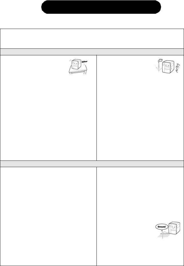
•Place the printer on a solid, stable, horizontal surface that is not subject to strong vibrations from adjacent mechanical devices.
•Avoid shaky or slanting tables, or
platforms that are liable to collapse under a heavy weight. If the printer is dropped or damaged, immediately turn off the power, pull out the power plug and contact a service center. In this case, continued use of the printer may cause a fire or electric shocks.
•Avoid installing the printer in direct sunlight, or in dusty, very hot or slippery areas. Also avoid placement in damp, unventilated or humid areas. If condensation forms, immediately turn off the power, and do not use the printer until the condensation disappears. Otherwise the moisture may cause electric shocks.
•Avoid placing the printer near large high-current equipment, as such equipment can cause spikes or undervoltages in the power supply.
•Do not leave containers of water or chemicals around the printer. If any liquid is spilled onto the printer, immediately turn off the power, pull out the
power cable from the AC outlet, and contact a sales outlet, dealer, or service center. In this case, continued use of the printer may cause fires or electric shocks.
•Do not move the printer with any paper loaded. The stack of paper may fall off, causing trips and accidents.
•When laying the printer down, be careful not to catch your foot or fingers under it.
•When moving the printer, be sure to pull out the power cable from the AC outlet, and check that any other external interface cables have been disconnected. Otherwise, the connected cables may be damaged, or may cause trips and falls, in addition to or a fire or electric shocks.
ELECTRICAL PRECAUTIONS
•Do not damage, break, or process the power cable. Hanging heavy objects on it, heating or pulling it may damage the power cable and cause fires or electric shocks.
•When the power cable is damaged (cable conductors are exposed or cut, etc.), contact a sales outlet, dealer, or service center. In this case, continued use of the printer may cause fires or electric shocks.
•Do not process, forcibly bend, twist, or pull the power cable. Continued use of such a cable may cause fires or electric shocks.
•If the printer emits any smoke or peculiar odors at any time, turn it OFF and prevent further usage until you have contacted a qualified service personnel.
•Do not use any other voltage except the specified power voltage for the printer that matches your domestic power supply. Otherwise, it may cause fires or electric shocks.
•Do not operate the power switch or handle the power cable with a wet hand.
•Do not insert or drop anything metallic or flammable into the openings of the printer (the cable outlet or mounting hole of the memory cartridge). Otherwise, immediately turn off the power, pull out the power cable, and contact a sales outlet, dealer, or service center. In this case, continued use of the printer may cause fires or electric shocks.
•To reduce electrical risks, be sure to connect the printer to ground before use. Also, try not to share the printer’s AC outlet with other electrical
equipment, especially those that draw high amounts of current or cause electrical interference.
Page 2-2 |
LM Basic 408e/412e Operator’s Manual |

Section 2: Installation
GENERAL PRECAUTIONS
•Head cleaning liquid (if supplied) is flammable. Never heat it or throw it into a fire. Keep it out of children’s reach to avoid accidental consumption. Should this occur, consult a doctor immediately.
•When opening/closing the cover, beware of getting your fingers caught. Also, hold the opening/closing cover well so that it will not slip and fall on your hand.
•After printing, the print head remains hot. When replacing paper or cleaning the printer immediately after printing, be careful not to burn yourself.
•Touching even the edge of the printer head may cause injuries. When replacing paper or cleaning the printer, be careful not to hurt yourself.
•If the printer will not be used for extended periods of time, disconnect the power cable for safety.
•When releasing and locking down the printer head, be careful not to catch any other foreign matter in it except label paper.
•Do not disassemble or perform modifications to the printer, as this renders the product unsafe. For maintenance, troubleshooting and repairs, consult a sales outlet, dealer, or service center for help, instead of attempting to perform this yourself. Renewable annual service contracts are available.
•When maintaining or cleaning the printer, always disconnect the power cable for safety.
•Do not insert your hand or other objects into the cutter.
•When loading roll paper, be careful not to catch your fingers between the paper and the feeder.
•Be careful not to hurt yourself when detaching the back cover of the fanfold through the hole and attaching it.
•The simplified cutter (where installed) is structured as a blade. Be careful not to cut yourself.
This equipment is a piece of Class B information technology equipment based on the standards of the Voluntary Control Council for Interference by Information Technology Equipment (VCCI). Although this equipment is for use in home environment, if it is used close to a radio or television set, it may cause poor reception. Handle it properly in accordance with the content from the instruction manual.
LM Basic 408e/412e Operator’s Manual |
Page 2-3 |
SECTION 2: INSTALLATION
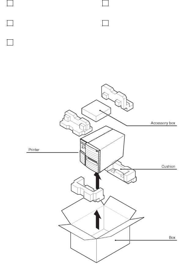
2.1 UNPACKING
When unpacking the printer, take note of the following:
|
|
The box should stay right-side up. |
|
|
If the printer was been stored in the |
1 |
4 |
||||
|
|
Lift the printer out of the box carefully. |
|
|
cold, allow it to reach room |
|
|
|
|
|
temperature before turning it on. |
|
|
|
|
|
|
|
|
Remove the plastic covering from the |
|
|
Set the printer on a solid, flat surface. |
2 |
5 |
||||
|
|
printer. |
|
|
Inspect the shipping container and |
|
|
|
|
|
printer for any sign of damage that |
|
|
|
|
|
may have occurred during shipping. |
|
|
Remove the accessory items from their |
|
|
|
|
3 |
|
|
|
|
|
|
protective containers. |
|
|
|
|
|
|
|
|
|
Note
The following illustrations are representative only. Your printer may not be packed exactly as shown, but the unpacking steps are similar.
Page 2-4 |
LM Basic 408e/412e Operator’s Manual |
Section 2: Installation
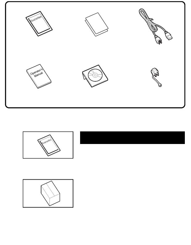
2.1.1 INCLUDED ACCESSORIES
After unpacking the printer, verify that the following materials are in the accessories or packaging:
Global Warranty |
Additional information |
document |
leaflets |
Power cable*
Operator’s Manual |
Accessory CD-ROM* |
Two-pole adaptor* |
* Items marked with an asterisk may be different from what you see here, or may be excluded.
Important!
Please fill out the Global Warranty card and submit it to us in order that we can provide fast and efficient after-sales service. For malfunctions under normal use, this product will be repaired free of charge according to the warranty terms applicable for the country of use.
Please do not discard the original packaging box and cushioning material after installing the printer. They may be needed in future, if the printer needs to be shipped for repairs.
LM Basic 408e/412e Operator’s Manual |
Page 2-5 |
SECTION 2: INSTALLATION
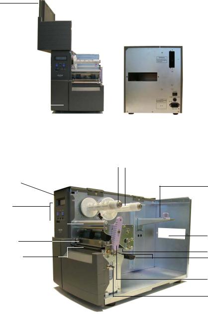
2.1.2 PARTS IDENTIFICATION
IDENTIFYING THE MAIN PRINTER PARTS
Front and Rear View
Main Cover
|
|
LCD screen |
|
|
|
|
|
|
|
|
|
|
|
|
|
|
|
|
|
|
|
|
|
|
|
|
|
|
|
|
|
|
|
|
|
|
|
|
|
|
|
|
|
|
|
|
|
|
|
|
|
|
Interface |
||||||||||||||||||
|
|
|
|
|
|
|
|
|
|
|
|
|
|
|
|
|
|
|
|
|
|
|
|
|
|
|
|
|
|
|
|
|
|
|
|
|
|
|
|
|
|
|
|
|
|
|
|
|
|
|
|
||||||||||||||||||||
|
|
|
|
|
|
|
|
|
|
|
|
|
|
|
|
|
|
|
|
|
|
|
|
|
|
|
|
|
|
|
|
|
|
|
|
|
|
|
|
|
|
|
|
|
|
|
|
|
|
Card Slot |
|||||||||||||||||||||
|
|
Operation Panel |
|
|
|
|
|
|
|
|
|
|
|
|
|
|
|
|
|
|
|
|
|
|
|
|
|
|
|
|
|
|
|
|
|
|
|
|
|
|
|
|
|
|
|
|
|
|
|
||||||||||||||||||||||
|
|
|
|
|
|
|
|
|
|
|
|
|
|
|
|
|
|
|
|
|
|
|
|
|
|
|
|
|
|
|
|
|
|
|
|
|
|
|
|
|
|
|
|
|
|
|
|
|
Fanfold paper slot |
||||||||||||||||||||||
|
|
|
|
|
|
|
|
|
|
|
|
|
|
|
|
|
|
|
|
|
|
|
|
|
|
|
|
|
|
|
|
|
|
|
|
|
|
|
|
|
|
|
|
|
|
|
|
|
|
|
|
|
|
|
|
|
|
|
|
||||||||||||
|
|
|
|
|
|
|
|
|
|
|
|
|
|
|
|
|
|
|
|
|
|
|
|
|
|
|
|
|
|
|
|
|
|
|
|
|
|
|
|
|
|
|
|
|
|
|
|
|
|
|
|
|
|
|
|
|
|
|
|
||||||||||||
|
|
|
|
|
|
|
|
|
|
|
|
|
|
|
|
|
|
|
|
|
|
|
|
|
|
|
|
|
|
|
|
|
|
|
|
|
|
|
|
|
|
|
|
|
|
|
|
|
|
|
|
|
|
|
|
|
|
|
|
Power switch |
|||||||||||
|
|
|
|
|
|
|
|
|
|
|
|
|
|
|
|
|
|
|
|
|
|
|
|
|
|
|
|
|
|
|
|
|
|
|
|
|
|
|
|
|
|
|
|
|
|
|
|
|
|
|
|
|
|
|
|
|
|
|
|
||||||||||||
|
|
Front Cover |
|
|
|
|
|
|
|
|
|
|
|
|
|
|
|
|
|
|
|
|
|
|
|
|
|
|
|
|
|
|
|
|
|
|
|
|
|
|
|
|
|
|
|
|
|
|
|
|
|
|
Fuse holder |
||||||||||||||||||
|
|
|
|
|
|
|
|
|
|
|
|
|
|
|
|
|
|
|
|
|
|
|
|
|
|
|
|
|
|
|
|
|
|
|
|
|
|
|
|
|
|
|
|
|
|
|
|
|
|
|
|
||||||||||||||||||||
|
|
|
|
|
|
|
|
|
|
|
|
|
|
|
|
|
|
|
|
|
|
|
|
|
|
|
|
|
|
|
|
|
|
|
|
|
|
|
|
|
|
|
|
|
|
|
|
|
|
|
|
||||||||||||||||||||
|
|
|
|
|
|
|
|
|
|
|
|
|
|
|
|
|
|
|
|
|
|
|
|
|
|
|
|
|
|
|
|
|
|
|
|
|
|
|
|
|
|
|
|
|
|
|
|
|
|
AC power socket |
|||||||||||||||||||||
|
|
|
|
|
|
|
|
|
|
|
|
|
|
|
|
|
|
|
|
|
|
|
|
|
|
|
|
|
|
|
|
|
|
|
|
|
|
|
|
|
|
|
|
|
|
|
|
|
|
||||||||||||||||||||||
|
|
|
|
|
|
|
|
|
|
|
|
|
|
|
|
|
|
|
|
|
|
|
|
|
|
|
|
|
|
|
|
|
|
|
|
|
|
|
|
|
|
|
|
|
|
|
|
|
|
|
|
|
|
|
|
|
|
|
|
|
|
|
|
|
|
|
|
|
|
|
|
|
|
|
|
|
|
|
|
|
|
|
|
|
|
|
|
|
|
|
|
|
|
|
|
|
|
|
|
|
|
|
|
|
|
|
|
|
|
|
|
|
|
|
|
|
|
|
|
|
|
|
|
|
|
|
|
|
|
|
|
|
|
|
|
|
|
|
|
|
|
|
|
Angled Front View (Main Cover removed)
Ribbon Take-Up Shaft |
|
|
|
Ribbon Feeder Shaft |
|
|
|
Front Cover
Operation panel and LCD
DIP Switches
Ribbon Roller 

Print Head
Platen Roller
Label holder
Fanfold paper slot
Ribbon Roller
Label Guide
Head Lock Lever
Screw for front cover
Page 2-6 |
LM Basic 408e/412e Operator’s Manual |
Section 2: Installation
2.1.2 PARTS IDENTIFICATION (CONT’D)
IDENTIFYING THE MAIN PRINTER PARTS
View of Front Panel
8888888888888888
8888888888888888
LINE STATUS FEED
|
|
|
|
|
|
|
|
|
|
|
|
|
|
|
|
|
|
|
|
|
|
|
|
|
|
|
|
|
|
|
|
|
|
|
|
|
|
|
|
|
|
|
|
|
|
|
|
|
|
|
|
|
|
|
|
|
|
|
|
|
|
|
|
|
|
|
|
|
|
|
|
|
|
|
|
|
|
|
|
|
|
|
|
|
|
|
|
|
|
|
|
|
|
|
|
|
|
|
|
|
|
|
|
|
|
|
|
|
|
|
|
|
|
|
|
|
|
|
|
|
|
|
|
|
|
|
|
|
|
|
|
|
|
|
|
|
|
|
|
|
|
|
|
|
|
|
|
|
|
OFFSET |
PITCH |
|||||||||||||
|
|
|
|
|
|
|
|
|
|
|
|
|
|
|
|
|
|
|
|
|
|
|
|
|
|
|
|
|||||
|
|
|
|
|
|
|
|
|
|
|
|
|
|
|
|
|
|
|
|
|
|
|
|
|
|
|
|
|||||
|
|
|
|
|
|
|
|
|
|
|
|
DSW |
|
|
|
|
|
|
|
|
|
|
|
|
||||||||
|
|
|
|
|
|
|
|
|
|
|
|
|
|
|
|
|
|
|
|
|
|
|
|
|
|
|
|
|
|
|
|
|
|
|
|
|
|
|
|
|
|
|
|
|
|
|
|
|
|
|
|
|
|
|
|
|
|
|
|
|
|
|
|
|
|
|
LCD screen |
|
|
|
|
|
|
|
|
|
|
|
||||||||||||||||||||
|
|
|
|
|
|
|
|
|
|
|
|
|
|
|
|
|
|
|
|
|
|
|
FEED button |
|
|
|||||||
|
|
|
|
|
|
|
|
|
|
|
|
|
|
|
|
|
|
|
|
|
|
|
|
|
||||||||
Icons, prompts and system messages |
|
|
|
|
|
|
|
|
|
|
|
|
|
|
|
|||||||||||||||||
|
. |
|
|
|
|
|
||||||||||||||||||||||||||
are displayed here. |
|
|
|
|
|
|
|
|
|
|
|
|
|
|
|
|
|
Feeds the label forward. When it is pressed once, |
||||||||||||||
|
|
|
|
|
|
|
|
|
the equivalent of a sheet of paper or label is ejected. |
|||||||||||||||||||||||
|
|
|
|
|
|
|
|
|
|
|
|
|
|
|
|
|
|
|
|
|
|
|
|
|
|
|
||||||
|
|
|
|
|
|
|
|
|
|
|
|
|
|
|
|
|
|
|
|
|
|
|
|
|
|
|
*There are times when the paper is not aligned prop- |
|||||
|
LINE button |
|
|
|
|
|
|
|
|
|
|
|
|
|
|
|
|
|
|
|
|
|
|
|
||||||||
|
|
|
|
|
|
|
|
|
|
|
|
|
|
|
|
|
|
|
|
|
|
|
|
erly when power is turned on or when the paper was |
||||||||
Takes the printer ONLINE (to proceed with printing) or |
|
|
|
|
|
|
set. In this case, always press the FEED button to |
|||||||||||||||||||||||||
OFFLINE (to perform configuration or other settings) |
|
|
|
|
|
|
align the paper properly. |
|||||||||||||||||||||||||
|
|
|
|
|
|
|
|
|
|
|
|
|
|
|
|
|
|
|
|
|
|
|
|
|
|
|
|
|
|
|||
|
Status LED |
|
|
|
|
|
|
|
|
|
|
|
|
|
|
|
|
|
|
|
|
|
|
|
|
|
Adjustment Potentiometers |
|
||||
|
|
|
|
|
|
|
|
|
|
|
|
|
|
|
|
|
|
|
|
|
|
|
|
|
|
|
||||||
Lights up and flashes to indicate exchange of data. |
|
|
|
|
|
|
PRINT: Adjusts the print darkness (print den- |
|||||||||||||||||||||||||
|
|
|
|
|
|
|
|
|
|
|
|
|
|
|
|
|
|
|
|
|
|
|
|
|
|
|
sity). |
|
|
|
|
|
|
|
|
|
|
|
|
|
|
|
|
|
|||||||||||||||||||||
DIP switch panel |
|
|
|
|
|
|
|
|
|
|
OFFSET: Adjusts the stop position offset values |
|||||||||||||||||||||
|
|
|
|
|
|
|
|
|
|
|
|
|
|
|
|
|
|
|
|
|
|
|
|
|||||||||
|
|
|
|
|
|
|
|
|
|
|
|
|
|
|
|
|
|
|
|
|
|
|
|
|
|
|
for the cutter, peeler and tear off modes (cutter, |
|||||
|
|
|
|
|
|
|
|
|
|
|
|
|
|
|
|
|
|
|
|
|
|
|
|
|
|
|
peeler must be installed). |
|||||
PITCH: Adjusts the vertical print position with reference to the top edge of a label.
LM Basic 408e/412e Operator’s Manual |
Page 2-7 |
SECTION 2: INSTALLATION
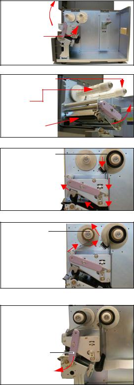
2.2 LOADING THE CARBON RIBBON
1.Lift up the main cover. Make sure that the cover is pushed upwards until it rests firmly on top of the printer, in case it falls downwards and injures you.
2.Pull the purple Head Lock lever upwards in a counterclockwise direction. The print head assembly will be lifted up to allow ribbon loading. The rightmost white plastic shaft is the Ribbon Feeder Shaft. The left-most shaft is the Ribbon Take-Up Shaft.
3.Insert the carbon ribbon in the Ribbon Feeder shaft. Push the ribbon roll inwards all the way, with the ribbon winding in a counterclockwise direction, as shown. Pull the ribbon around the print head assembly so it reaches the Ribbon Take-up Shaft. The dull side of the ribbon should be facing down.
4.Insert an empty ribbon core into the Ribbon TakeUp Shaft. If necessary, use secure the ribbon with adhesive tape, and wind the ribbon around the core a few times.
Note:
If in doubt about the ribbon path, refer to the useful diagram pasted inside the Main Cover.
5.Press the purple Head Lock lever clockwise and downwards to lock the print head assembly into place. The ribbon is now loaded.
Note:
To remove the ribbon, reverse the steps described here. For maximum print quality and printer durability use genuine SATO carbon ribbons.
 Caution
Main Cover
Head Lock  lever (purple)
Ribbon Feeder
Shaft
Ribbon
Take-Up Shaft
Print head assembly
Ribbon Feeder Shaft
Carbon ribbon
Ribbon Take-
Up Shaft
Head Lock Lever (purple)
•When replacing the carbon ribbon, bear in mind that the print head and its surrounding area remain hot. Keep your fingers away from these areas to prevent injury.
•Avoid touching even the edge of the print head with your bare hands.
Page 2-8 |
LM Basic 408e/412e Operator’s Manual |
Section 2: Installation
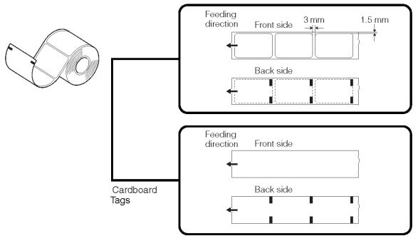
2.3 LOADING LABELS
This printer is designed to print on roll paper supplied via a separate label supply stand.
The printing mechanism can be set to detect the I-mark on the paper to feed each label correctly.
Note:
For optimal print performance and durability, please use SATO-certified label and ribbon supplies on this printer. Using supplies not tested and approved for use by SATO can result in unnecessary wear and damage to vital parts of the printer, and may void the warranty.
Roll Paper Characteristics
Labels
CAUTION
If your labels are less than the full width of the print head, the outside edge will eventually wear out a small portion of the print head, resulting in an area that will not print. Special care must be taken if you plan to use multiple widths of labels, since the damaged portion of the print head caused from edge wear on a more narrow label may affect the printing on a wider label. We suggest you plan your print formats carefully to avoid using the area of possible damage on the print head when using a wider label. The small area of damage will have no effect on printing with the undamaged part of the print head.
Damage from a label edge is physical damage and is unavoidable. It is not covered by warranty. It is possible to delay such damage by always ensuring that the ribbon used is wider than the label stock. This will help to protect the print head from label edge damage.
LM Basic 408e/412e Operator’s Manual |
Page 2-9 |

SECTION 2: INSTALLATION
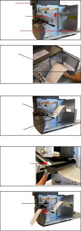
2.3 LOADING LABELS (CONT’D)
2.3.1 Loading Roll Paper
1.Lift up the main cover. Make sure that the cover is pushed upwards until it locks firmly in place so that it will not fall downwards and injure your hands.
Release the purple Head Lock lever by pushing it upwards. The print head assembly will be lifted up to allow ribbon and label loading.
Main Cover
Label Holder
Label
Guide Plate
2. Load the ribbon rolls as described earlier. Pull down the Label Guide Plate. Then insert a label roll onto the Label Holder. Push the purple Label Stopper against the label roll to prevent it from slipping sideways.
Label |
Stopper |
3. Guide the label under the ribbon, making sure it  goes under the paper sensors. The label should
  emerge at a perpendicular angle from the print
  head. Head
Lock lever latched in place
4.Fasten the Head Lock Lever by pushing it
clockwise until the print head locks into place. Pull up the Label Guide Plate to and push it against the outside edge of the label to restrict and straighten the label path. Now turn the purple Head Lock Lever clockwise to latch the print head assembly back in place.
5.The illustration below summarizes the ribbon and label loading paths for your reference. To check whether your ribbon and label are loading correctly, perform a test print.
 Caution
•When replacing paper, bear in mind that the print head and its surrounding area remain hot. Keep your fingers away from these areas to prevent injury.
•Avoid touching even the edge of the print head with your bare hands.
Page 2-10 |
LM Basic 408e/412e Operator’s Manual |
Section 2: Installation
2.3 LOADING LABELS (CONT’D)
2.3.2 Loading Fanfold Paper
1.Lift up the main cover. Make sure that the cover is pushed upwards until it locks firmly in place. Remove the fanfold slot cover by removing two screws. Pull the Head Lock Lever upward to release the print head assembly.
2.Stack the fanfold paper behind the printer and pull it through the fanfold slot and over the Label Holder. Push the purple Label Stopper so that it presses the label lightly against the side of the printer.
3.Guide the label under the label sensor and print head, and out through the front of the printer. Make sure the label goes under the black plastic guide bar adjacent to the Label Guide.
4.Use the metal plate of the Label Guide to press against the paper so that the paper runs at a perpendicular angle from the print head.
5.Load ribbon media and labels, then turn the purple Head Lock Lever clockwise to latch the print head assembly back in place. and perform a test print to check whether your ribbon and label are loaded correctly.
 Caution
Main
Cover
Head Lock
Lever
Fanfold slot cover
Fanfold paper
Label
Stopper
Paper Sensor
Label Guide 

Guide Bar
Label Guide
Head Lock lever latched in place
•When replacing paper, bear in mind that the print head and its surrounding area remain hot. Keep your fingers away from these areas to prevent injury.
•Avoid touching even the edge of the print head with your bare hands.
LM Basic 408e/412e Operator’s Manual |
Page 2-11 |
SECTION 2: INSTALLATION
2.3 LOADING LABELS AND TAGS (CONT’D)
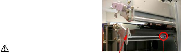
2.3.3 Adjusting the Paper Sensor
Adjustment of the paper sensors (I-mark and Gap sensors) is usually not necessary, but the procedure is described here when you need to make adjustments.
1.Lift up the main cover. Make sure that the cover is pushed upwards until it locks firmly in place so that it will not fall downwards and injure your hands.
2.The sensor assembly is located just under the Label Guide Shaft. Turn the purple Sensor Adjustment knob to adjust the sensors’ position.
3.After adjustment, feed a few labels and do a test
print to see if the sensor is working properly. Adjust the label pitch if necessary.
Caution
• When closing the front cover, be careful not to injure your fingers |
Label Guide Plate Sensor Adjustment knob |
due to a sudden release of the heavy cover. |
|
Page 2-12 |
LM Basic 408e/412e Operator’s Manual |
Loading...