


®
CT 400 and CT410
Desk Top Printers
Operator and Technical
Reference Manual
PN 9001069A
SATO UK Limited
Valley Road, Harwich
Essex CO12 4RR
Tel: 01255 240000
Fax: 01255 240111
Tech Support Hotline: 01255 252828
Email: techsupport@satouk.com
www.satouk.com
© Copyright 2005
SATO UK Limited
Warning: This equipment complies with the requirements in Part 15 of FCC rules for a Class A computing device. Operation of this equipment in a residential area may cause unacceptable interference to radio and TV reception requiring the operator to take whatever steps are necessary to correct the interference.
All rights reserved. No part of this document may be reproduced or issued to third parties in any form whatsoever without the express permission of SATO America, Inc. The materials in this document is provided for general information and is subject to change without notice. SATO America, Inc. assumes no responibilities for any errors that may appear.

PREFACE
CT SERIES PRINTER OPERATOR’S MANUAL
The CT Series Printer Operator’s Manual contains basic information about the printer such as setup, installation, cleaning and maintenance. It also contains complete instructions on how to use the operator panel to configure the printer. The following is a brief description of each section in this manual.
SECTION 1. PRINTER OVERVIEW
This section contains a discussion of the printer specifications and optional features.
SECTION 2. INSTALLATION AND CONFIGURATION
This section contains instructions on how to unpack and set up the printer, load the labels and ribbon, and how to use the operator panel to configure the printer.
SECTION 3. CLEANING AND MAINTENANCE
This section contains instructions on how to clean and maintain the printer.
SECTION 4. PROGRAMMING
This section introduces the SATO printer programming language. It contains the commands that are used with the printer to produce labels with bar codes, alphanumeric data and graphics.
SECTION 5. INTERFACE SPECIFICATIONS
This section contains the printer’s interface specifications, which include detailed information on how to properly interface your printer to the host system.
SECTION 6. TROUBLESHOOTING
This section contains troubleshooting procedures to follow in the event you have printer problems.
SATO CT Series Printers |
9001069A |
Page - i |
Preface
APPENDICES
APPENDIX A: Command Code Quick Reference
APPENDIX B: Bar Code Specifications
APPENDIX C: Custom Characters and Graphics
Page - ii |
9001069A |
SATO CT Series Printers |

Preface
TABLE OF CONTENTS
SECTION 1. PRINTER OVERVIEW |
|
Introduction . . . . . . . . . . . . . . . . . . . . . . . . . . . . . |
1-1 |
General Printer Specifications . . . . . . . . . . . . . . . . . . . . |
1-2 |
Character Fonts . . . . . . . . . . . . . . . . . . . . . . . . . . . . |
1-4 |
Bar Codes . . . . . . . . . . . . . . . . . . . . . . . . . . . . . . . |
1-5 |
Physical . . . . . . . . . . . . . . . . . . . . . . . . . . . . . . . . |
1-6 |
Optional Accessories . . . . . . . . . . . . . . . . . . . . . . . . . |
1-7 |
SECTION 2. INSTALLATION AND CONFIGURATION |
|
Introduction . . . . . . . . . . . . . . . . . . . . . . . . . . . . . |
2-1 |
Unpacking . . . . . . . . . . . . . . . . . . . . . . . . . . . . . . |
2-2 |
Setting Up the Printer . . . . . . . . . . . . . . . . . . . . . . . . |
2-3 |
Loading Ribbon (CT4XXTT Only) . . . . . . . . . . . . . . . . . . . |
2-5 |
Loading Media . . . . . . . . . . . . . . . . . . . . . . . . . . . . |
2-7 |
Label Sensing . . . . . . . . . . . . . . . . . . . . . . . . . . . . . |
2-10 |
Operator Panel . . . . . . . . . . . . . . . . . . . . . . . . . . . . |
2-11 |
Rear Connector Panel . . . . . . . . . . . . . . . . . . . . . . . . . |
2-12 |
Configuration Panel . . . . . . . . . . . . . . . . . . . . . . . . . . |
2-13 |
Offset . . . . . . . . . . . . . . . . . . . . . . . . . . . . . . . . |
2-16 |
Potentiometer Adjustments . . . . . . . . . . . . . . . . . . . . . . |
2-16 |
Hex Dump Diagnostic Label . . . . . . . . . . . . . . . . . . . . . |
2-19 |
Print Test Labels . . . . . . . . . . . . . . . . . . . . . . . . . . . |
2-20 |
SECTION 3. CTEANING AND MAINTENANCE |
|
Introduction . . . . . . . . . . . . . . . . . . . . . . . . . . . . . |
3-1 |
Procedures . . . . . . . . . . . . . . . . . . . . . . . . . . . . . . |
3-1 |
Adjusting the Print Quality . . . . . . . . . . . . . . . . . . . . |
3-1 |
Darkness . . . . . . . . . . . . . . . . . . . . . . . . . . . |
3-1 |
Print Speed . . . . . . . . . . . . . . . . . . . . . . . . . . |
3-2 |
Cleaning the Print Head, Platen and Rollers . . . . . . . . . . . |
3-2 |
Replacing the Print Head . . . . . . . . . . . . . . . . . . . . . |
3-3 |
Cleaning the Sensors . . . . . . . . . . . . . . . . . . . . . . . |
3-5 |
SATO CT Series Printers |
9001069A |
Page - iii |

Preface
SECTION 4. PROGRAMMING |
|
Introduction . . . . . . . . . . . . . . . . . . . . . . . . . . . . . |
4-1 |
The SATO CT Programming Language . . . . . . . . . . . . . . . . |
4-1 |
Protocol Control Codes . . . . . . . . . . . . . . . . . . . . . . . . |
4-2 |
Using Basic . . . . . . . . . . . . . . . . . . . . . . . . . . . . . . |
4-2 |
The Print Area . . . . . . . . . . . . . . . . . . . . . . . . . . . . |
4-4 |
Rotated Fields . . . . . . . . . . . . . . . . . . . . . . . . . . . . |
4-6 |
Command Default Settings . . . . . . . . . . . . . . . . . . . . . . |
4-6 |
Command Codes . . . . . . . . . . . . . . . . . . . . . . . . . . . |
4-6 |
Bar Codes . . . . . . . . . . . . . . . . . . . . . . . . . . . . . |
4-9 |
Bar Codes, Expansion . . . . . . . . . . . . . . . . . . . . . . . |
4-14 |
Bar Codes, Variable Ratio . . . . . . . . . . . . . . . . . . . . . |
4-15 |
Base Reference Point . . . . . . . . . . . . . . . . . . . . . . . |
4-17 |
Characters, Custom Designed . . . . . . . . . . . . . . . . . . . |
4-29 |
Character Expansion . . . . . . . . . . . . . . . . . . . . . . . |
4-21 |
Character, Fixed Spacing . . . . . . . . . . . . . . . . . . . . . |
4-23 |
Character Pitch . . . . . . . . . . . . . . . . . . . . . . . . . . |
4-24 |
Character, Proportional Spacing . . . . . . . . . . . . . . . . . |
4-26 |
Clear Print Job(s) and Memory . . . . . . . . . . . . . . . . . . |
4-27 |
Continuous Forms Printing . . . . . . . . . . . . . . . . . . . . |
4-28 |
Copy Image Area . . . . . . . . . . . . . . . . . . . . . . . . . |
4-29 |
Cut Job . . . . . . . . . . . . . . . . . . . . . . . . . . . . . . |
4-31 |
Cut . . . . . . . . . . . . . . . . . . . . . . . . . . . . . . . . |
4-32 |
Cut Last . . . . . . . . . . . . . . . . . . . . . . . . . . . . . . |
4-33 |
Fonts, U, S, M, OA, OB, XU, XS and XM . . . . . . . . . . . . . |
4-34 |
Font/Graphic Recall . . . . . . . . . . . . . . . . . . . . . . . |
4-36 |
Font, Raster . . . . . . . . . . . . . . . . . . . . . . . . . . . . |
4-37 |
Fonts, Vector . . . . . . . . . . . . . . . . . . . . . . . . . . . |
4-38 |
Fonts, WB,WL, XB and XL . . . . . . . . . . . . . . . . . . . . |
4-40 |
Form Overlay Recall . . . . . . . . . . . . . . . . . . . . . . . |
4-42 |
Form Overlay Store . . . . . . . . . . . . . . . . . . . . . . . . |
4-43 |
Graphics, Custom . . . . . . . . . . . . . . . . . . . . . . . . . |
4-44 |
Job ID Store . . . . . . . . . . . . . . . . . . . . . . . . . . . |
4-46 |
Journal Print . . . . . . . . . . . . . . . . . . . . . . . . . . . |
4-47 |
Lines and Boxes . . . . . . . . . . . . . . . . . . . . . . . . . . |
4-48 |
Job Name . . . . . . . . . . . . . . . . . . . . . . . . . . . . . |
4-50 |
Label/Tag Select . . . . . . . . . . . . . . . . . . . . . . . . . |
4-51 |
Line Feed . . . . . . . . . . . . . . . . . . . . . . . . . . . . . |
4-52 |
Media Size . . . . . . . . . . . . . . . . . . . . . . . . . . . . |
4-54 |
Off-Line . . . . . . . . . . . . . . . . . . . . . . . . . . . . . . |
4-55 |
Postnet . . . . . . . . . . . . . . . . . . . . . . . . . . . . . . |
4-56 |
Print Darkness . . . . . . . . . . . . . . . . . . . . . . . . . . |
4-57 |
Print Position . . . . . . . . . . . . . . . . . . . . . . . . . . . |
4-58 |
Print Quantity . . . . . . . . . . . . . . . . . . . . . . . . . . |
4-60 |
Print Speed . . . . . . . . . . . . . . . . . . . . . . . . . . . . |
4-61 |
Repeat Label . . . . . . . . . . . . . . . . . . . . . . . . . . . |
4-62 |
Replace Data (Partial Edit) . . . . . . . . . . . . . . . . . . . . |
4-63 |
Reverse Image . . . . . . . . . . . . . . . . . . . . . . . . . . |
4-65 |
Rotate, Fixed Base Reference Point . . . . . . . . . . . . . . . . |
4-67 |
Page - iv |
9001069A |
SATO CT Series Printers |

|
Preface |
Sequential Numbering . . . . . . . . . . . . . . . . . . . . . . |
4-68 |
Start/Stop Label . . . . . . . . . . . . . . . . . . . . . . . . . |
4-70 |
Two-Dimensional Symbols . . . . . . . . . . . . . . . . . . . . |
4-71 |
Data Matrix, Data Format . . . . . . . . . . . . . . . . . . . |
4-72 |
Data Matrix, Data Print . . . . . . . . . . . . . . . . . . . . |
4-74 |
Dat Matrix Sequential Numbering . . . . . . . . . . . . . . |
4-75 |
Maxicode . . . . . . . . . . . . . . . . . . . . . . . . . . . |
4-77 |
PDF417 . . . . . . . . . . . . . . . . . . . . . . . . . . . . |
4-79 |
Printer Configuration Commands . . . . . . . . . . . . . . . . . |
4-81 |
Protocol Codes . . . . . . . . . . . . . . . . . . . . . . . . |
4-82 |
Printer Setting . . . . . . . . . . . . . . . . . . . . . . . . |
4-83 |
Print Mode . . . . . . . . . . . . . . . . . . . . . . . . . . |
4-86 |
Print Type . . . . . . . . . . . . . . . . . . . . . . . . . . . |
4-87 |
Pitch Offset . . . . . . . . . . . . . . . . . . . . . . . . . . |
4-88 |
Sensor Type . . . . . . . . . . . . . . . . . . . . . . . . . . |
4-89 |
Serial Interface Parameters . . . . . . . . . . . . . . . . . . |
4-90 |
SECTION 5. INTERFACE SPECIFICATIONS |
|
Introduction . . . . . . . . . . . . . . . . . . . . . . . . . . . . . |
5-1 |
Interface Types . . . . . . . . . . . . . . . . . . . . . . . . . . . . |
5-1 |
The Receive Buffer . . . . . . . . . . . . . . . . . . . . . . . . . . |
5-2 |
RS232C Serial Interface . . . . . . . . . . . . . . . . . . . . . . . |
5-3 |
IEEE 1284 Parallel Interface . . . . . . . . . . . . . . . . . . . . . |
5-3 |
Optional RS232 Interface . . . . . . . . . . . . . . . . . . . . . . . |
5-5 |
General Specifications . . . . . . . . . . . . . . . . . . . . . . |
5-5 |
Electrical Specifications . . . . . . . . . . . . . . . . . . . . . . |
5-5 |
Pin Assignments . . . . . . . . . . . . . . . . . . . . . . . . . |
5-5 |
Ready/Busy Flow Control . . . . . . . . . . . . . . . . . . . . . |
5-6 |
X-On/X-Off Flow Control . . . . . . . . . . . . . . . . . . . . . |
5-57 |
Optional Universal Serial Bus (USB) Interface . . . . . . . . . . . . |
5-7 |
Optional Local Area Network Interface . . . . . . . . . . . . . . . . |
5-8 |
Bi-Directional Communications . . . . . . . . . . . . . . . . . . . . |
5-8 |
SECTION 6. TROUBLESHOOTING |
|
Initial Checklist . . . . . . . . . . . . . . . . . . . . . . . . . . . . |
6-1 |
Using the IEEE 1284 Parallel Interface . . . . . . . . . . . . . . . . |
6-1 |
Using the RS232C Serial Interface . . . . . . . . . . . . . . . . . . |
6-3 |
Error Signals . . . . . . . . . . . . . . . . . . . . . . . . . . . . . |
6-4 |
SATO CT Series Printers |
9001069A |
Page - v |
Preface
APPENDICES |
|
APPENDIX A: Command Code Quick Reference |
|
APPENDIX B: Bar Code Specifications |
|
Bar Code Symbologies . . . . . . . . . . . . . . . . . . . . . . |
B-1 |
Codabar . . . . . . . . . . . . . . . . . . . . . . . . . . . . |
B-2 |
Code 39 . . . . . . . . . . . . . . . . . . . . . . . . . . . . |
B-3 |
Interleaved Two of Five (I 2/5) . . . . . . . . . . . . . . . . |
B-4 |
UPC-A/EAN-13 . . . . . . . . . . . . . . . . . . . . . . . . |
B-5 |
EAN-8 . . . . . . . . . . . . . . . . . . . . . . . . . . . . . |
B-6 |
Industrial Two of Five . . . . . . . . . . . . . . . . . . . . |
B-8 |
Matrix Two of Five . . . . . . . . . . . . . . . . . . . . . . |
B-9 |
Code 128 . . . . . . . . . . . . . . . . . . . . . . . . . . . |
B-10 |
MSI . . . . . . . . . . . . . . . . . . . . . . . . . . . . . . |
B-11 |
Code 93 . . . . . . . . . . . . . . . . . . . . . . . . . . . . |
B-12 |
UPC-E . . . . . . . . . . . . . . . . . . . . . . . . . . . . . |
B-13 |
Bookland (UPC/EAN Supplements) . . . . . . . . . . . . . |
B-14 |
UCC-128 . . . . . . . . . . . . . . . . . . . . . . . . . . . |
B-15 |
Postnet . . . . . . . . . . . . . . . . . . . . . . . . . . . . |
B-17 |
Data Matrix . . . . . . . . . . . . . . . . . . . . . . . . . . |
B-18 |
Maxicode . . . . . . . . . . . . . . . . . . . . . . . . . . . |
B-20 |
PDF417 . . . . . . . . . . . . . . . . . . . . . . . . . . . . |
B-21 |
Code 128 Character Table . . . . . . . . . . . . . . . . . . |
B-22 |
APPENDIX C: Custom Characters and Graphics |
|
Custom Designed Characters Example . . . . . . . . . . . . . . |
C-1 |
Custom Graphics Example . . . . . . . . . . . . . . . . . . . . |
C-4 |
PCX Graphics Example . . . . . . . . . . . . . . . . . . . . . . |
C-8 |
Page - vi |
9001069A |
SATO CT Series Printers |

SECTION 1.
PRINTER OVERVIEW
INTRODUCTION
The SATO CT Series Thermal Transfer Printers are complete, high-performance on-site labeling systems. All printer parameters are user programmable using software commands or the utility program provided. All popular bar codes and 15 human-readable fonts, including a vector font and two raster fonts, are resident in memory providing literally thousands of type styles and sizes. Additional fonts can be downloaded into memory.
The Operator’s Manual will help you understand the basic operations of the printer such as setup, installation, configuration, cleaning and maintenance.
The major differences in the CT400 and the CL410 printers is the resolution of the head. The CT400 with its 203 dpi head provides an economical labeling solution for most applications. It can print labels up to four inches wide. The CT410’s higher 305 dpi resolution provides greater detail for graphics and small point size text.
The CT Series printers use a subset of the standard SATO Command Language. The CT400 and CT410 share the same command set, the only differences are the allowable values representing the print positions on the label. These values are specified in “dots” and will vary depending upon the resolution of the printer and the amount of memory available for imaging the label. The allowable range for each printer is specified in a table for those command codes.
This commonalty makes it very easy to convert labels from one CT printer to another without having to create an entirely different command stream. There are some caveats that must be observed though to compensate for the different resolution print heads. The effect of the different printer resolutions are best illustrated by taking a label designed for a 203 dpi printer and sending the command stream to its 305 dpi counterpart. The label printed will be an exact two-thirds scale, including the fonts, bar code dimensions and line lengths/widths. The only exceptions are PostNet and Maxicode which have only one legal size and the printer resolution is automatically compensated for by the printer. Conversely, a label designed for a 305 dpi printer and sent to its 203 dpi cousin will be one-third larger. It probably will be “truncated” if the label size is larger than the maximum allowable for the printer.
The following general information is presented in this section:
∙General Printer Specifications
∙Optional Accessories
SATO CT Series Printers |
9001069A |
Page 1-1 |

Section 1. Printer Overview
GENERAL PRINTER SPECIFICATIONS
SPECIFICATION |
CT400 |
|
CT410 |
|
|
|
|
|
|
|
|
|
|
|
|
Method |
Direct or Thermal Transfer |
||
|
|
|
|
Speed (User Selectable) |
2 to 6 ips |
|
2 to 4 ips |
|
50 to 150 mm/s |
|
50 to 100 mm/s |
|
|
|
|
Print Module (Dot Size) |
.0049 in. |
|
.0033 in. |
|
.125 mm |
|
.083 mm |
|
|
|
|
Resolution |
203 dpi |
|
305 dpi |
|
8 dpmm |
|
12 dpmm |
|
|
|
|
Maximum Print Width |
|
4.1 in. |
|
|
|
104 mm |
|
|
|
|
|
Maximum Print Length |
|
15.6 in. |
|
|
|
400 mm |
|
|
|
|
|
MEDIA |
|
|
|
|
|
|
|
Minimum Width |
|
.90 in. (23 mm) |
|
|
|
|
|
Minimum Length |
|
.60 in. (15 mm) |
|
|
|
|
|
Maximum Width |
|
4.6 in. (118 mm) |
|
|
|
||
Type |
Die Cut Labels, Fan-Fold, Tag Stock or Continuous |
||
|
|
||
Caliper |
0.003 to .0075 in. (0.08 to 0.19 mm) |
||
|
|
||
Roll OD (max) |
4.3 in. (110 mm), Face-Out Wind |
||
|
|
|
|
Core ID (min) |
|
1.5 in. (40 mm) |
|
|
|
|
|
SENSING |
|
|
|
|
|
|
|
See-Thru for labels or tags |
Fixed, 0.25" (6.3 mm) from left label edge |
||
|
|
||
Reflective Eye-Mark |
Fixed, 0.20" (5 mm) from left label edge |
||
|
|
|
|
Continuous Form |
|
Sensor not used |
|
|
|
|
|
RIBBON |
|
|
|
|
|
|
|
Maximum Width |
|
4.4 in. (111 mm) |
|
|
|
|
|
Length |
|
325 ft. (100 m) |
|
|
|
|
|
Core ID |
|
0.5 in. (12.7 mm) |
|
|
|
||
Thickness |
4.5 micron, Face-Out Wind |
||
|
|
|
|
|
|
|
|
All specifications subject to change without notice.
Page 1-2 |
9001069A |
SATO CT Series Printers |
|
|
Section 1. Printer Overview |
|
|
|
|
|
SPECIFICATION |
CT400 |
|
CT410 |
|
|
|
|
CONTROLS AND SIGNALS |
|
|
|
|
|
|
|
On-Line LED |
|
Green |
|
|
|
|
|
Power LED |
|
Green |
|
|
|
|
|
Error LED |
|
Red |
|
|
|
||
LED Display Panel |
7 Segment Single Character |
||
|
|
|
|
On/Off-Line Switch |
|
Front Panel |
|
|
|
|
|
Label Feed Switch |
|
Front Panel |
|
|
|
|
|
Power On/Off Switch |
|
Front Panel |
|
|
|
|
|
POTENTIOMETER ADJUSTMENTS |
|
|
|
|
|
|
|
Pitch Offset/Print Darkness |
|
Front Panel |
|
|
|
|
|
Reflective Sensor Adjustment |
|
Front Panel |
|
|
|
|
|
See-thru Sensor Adjustment |
|
Front Panel |
|
|
|
|
|
INTERFACE CONNECTIONS |
|
|
|
|
|
|
|
Parallel (Standard) |
|
IEEE 1284 |
|
|
|
||
Serial (Option) |
RS232C (9600 to 57.6K bps) |
||
|
Hardware Flow Control (Ready/Busy) |
||
|
Software Flow Control (X-On/X-Off) |
||
|
Bi-directional Status |
||
|
|
||
USB (Option) |
USB Specification Version 1.0 |
||
|
|
|
|
PROCESSING |
|
|
|
|
|
|
|
CPU |
|
32 Bit RISC |
|
|
|
|
|
EEPROM |
|
8KB |
|
|
|
|
|
SDRAM |
|
8MB |
|
|
|
|
|
Flash ROM |
|
2MB |
|
|
|
|
|
Flash ROM Option |
|
8MB |
|
|
|
|
|
Receive Buffer |
|
2.95MB |
|
|
|
|
|
|
|
|
|
|
|
|
|
All specifications subject to change without notice.
SATO CT Series Printers |
9001069A |
Page 1-3 |

Section 1. Printer Overview
CHARACTER FONTS
SPECIFICATION |
CT400 |
CT410 |
|
|
|
MATRIX FONTS |
|
|
|
|
|
U Font |
(5 dots W x 9 dots H) |
|
|
|
|
S Font |
(8 dots W x 15 dots H) |
|
|
|
|
M Font |
(13 dots W x 20 dots H) |
|
|
|
|
XU Font |
(5 dots W x 9 dots H) Helvetica |
|
|
|
|
XS Font |
(17 dots W x 17 dots H) Univers Condensed Bold |
|
|
|
|
XM Font |
(24 dots W x 24 dots H) Univers Condensed Bold |
|
|
|
|
OA Font |
(15 dots W x 22 dots H) OCR-A |
(22 dots W x 33 dots H) OCR A |
|
|
|
OB Font |
20 dots W x 24 dots H) OCR-B |
(30 dots W x 36 dots H) OCR B |
|
|
|
AUTO SMOOTHING FONTS |
|
|
|
|
|
WB(1) |
WB Font (18 dots W x 30 dots H) |
|
WL(1) |
WL Font (28 dots W x 52 dots H) |
|
XB |
XB Font (48 dots W x 48 dots H) Univers Condensed Bold |
|
|
|
|
XL |
XL Font (48 dots W x 48 dots H) Sans Serif |
|
|
|
|
VECTOR FONT |
|
|
|
|
|
|
Proportional or Fixed Spacing |
|
|
Font Size 50 x 50 dots to 999 x 999 dots |
|
|
Helvetica, 10 Font Variations |
|
|
|
|
RASTER FONTS |
|
|
|
|
|
A Font(1) |
CG Times |
|
B Font(1) |
CG Triumvirate |
|
DOWNLOADABLE FONTS |
|
|
|
|
|
|
TrueType Fonts with Utility Program |
|
|
|
|
CHARACTER CONTROL |
|
|
|
|
|
|
Expansion up to 12X in either the X or Y coordinates |
|
|
Character Pitch control |
|
|
Line Space control |
|
|
Journal Print facility |
|
|
0°, 90°, 180° and 270° Rotation |
|
|
|
|
|
|
|
(1) Not available on early models.
All specifications subject to change without notice.
Page 1-4 |
9001069A |
SATO CT Series Printers |
|
|
|
Section 1. Printer Overview |
BAR CODES |
|
|
|
|
|
|
|
|
|
|
|
SPECIFICATION |
CT400 |
|
CT410 |
|
|
|
|
SYMBOLOGIES |
|
|
|
|
|
|
|
|
Bookland (UPC/EAN Supplemental) |
||
|
|
EAN-8, EAN-13 |
|
|
|
CODABAR |
|
|
|
Code 39 |
|
|
|
Code 93 |
|
|
|
Code 128 |
|
|
|
Interleaved 2 of 5 |
|
|
|
Industrial 2 of 5 |
|
|
|
Matrix 2 of 5 |
|
|
|
MSI |
|
|
|
POSTNET |
|
|
|
UCC/EAN-128 |
|
|
|
UPC-A and UPC-E |
|
|
|
Data Matrix |
|
|
|
Maxicode |
|
|
|
PDF417 |
|
|
|
Micro PDF |
|
|
|
Truncated PDF |
|
|
|
||
Ratios |
1:2, 1:3, 2:5 User definable bar widths |
||
|
|
||
Bar Height |
4 to 600 dots, User programmable |
||
|
|
|
|
Rotation |
|
0°, 90°, 180° and 270° |
|
|
|
|
|
OTHER FEATURES |
|
|
|
|
|
|
|
Sequential Numbering |
Sequential numbering of both numerics and bar codes |
||
|
|
||
Custom Characters |
RAM storage for special characters |
||
|
|
||
Graphics |
Full dot addressable graphics, SATO Hex/Binary and PCX(1) format |
||
Form Overlay |
Form overlay for high-speed editing of complex formats. |
||
|
|
|
|
|
|
|
|
(1) Not available on early models.
All specifications subject to change without notice.
SATO CT Series Printers |
9001069A |
Page 1-5 |

Section 1. Printer Overview
PHYSICAL
SPECIFICATION |
CT400 |
|
CT410 |
|
|
|
|
DIMENSIONS |
|
|
|
|
|
|
|
Wide |
|
7.8 in. (198 mm) |
|
|
|
|
|
Deep |
|
9.1 in. (230 mm) |
|
|
|
|
|
High |
|
6.5 in. (181 mm) |
|
|
|
|
|
WEIGHT |
|
6.6 lbs (3 Kg) |
|
|
|
|
|
POWER REQUIREMENTS |
|
|
|
|
|
|
|
Voltage |
|
110 V (±10 %) |
|
|
|
220V (±10 %) |
|
|
|
50/60 Hz (±1%) |
|
|
|
||
Power Consumption |
150W Operating at 30% density |
||
|
|
|
|
ENVIRONMENTAL |
|
|
|
|
|
|
|
Operating Temperature |
|
41° to 104°F (5° to 40°C) |
|
|
|
|
|
Storage Temperature |
|
-0° to 104°F (-20° to 40°C) |
|
|
|
||
Operating Humidity |
30-80 % RH, non-condensing |
||
|
|
||
Storage Humidity |
20-80% RH, non-condensing |
||
|
|
|
|
Electrostatic Discharge |
|
8KV |
|
|
|
|
|
REGULATORY APPROVALS |
|
|
|
|
|
|
|
Safety |
|
UL, CSA |
|
|
|
|
|
RFI/EMI |
|
FCC Class B |
|
|
|
|
|
|
|
|
|
All specifications subject to change without notice.
Page 1-6 |
9001069A |
SATO CT Series Printers |
|
|
|
|
Section 1. Printer Overview |
OPTIONAL ACCESSORIES |
|
|
|
|
|
|
|
|
|
|
|
|
|
|
ACCESSORY |
|
CT400 |
|
CT410 |
|
|
|
|
|
|
|
|
|
|
LABEL CUTTER |
|
Internal option allowing labels to be cut at specified intervals. |
||
|
|
Controlled through programming. Factory installed only. |
||
|
|
|
||
LABEL DISPENSER |
|
Internal option allowing labels to be peeled from backing for |
||
|
|
immediate (on demand) application. Factory installed only. |
||
|
|
|
||
LABEL REWINDER |
|
External accessory rewinds labels onto a roll after they are printed. |
||
|
|
|
||
SERIAL INTERFACE |
|
High Speed RS232 Interface option, 9600 to 57.6KB. Factory |
||
|
|
installed only. |
|
|
|
|
|
||
ETHERNET INTERFACE |
|
TCP/IP Protocol Interface option. Factory installed only. |
||
|
|
|
||
USB INTERFACE |
|
Universal Serial Bus Interface option. Factory installed only. |
||
|
|
|
||
COAX/TWINAX INTERFACE |
|
External Coax/Triax I/F Interface accessory. Coax I/F emulates an |
||
|
|
IBM 3287-2 printer with a standard Type A BNC connector. Twinax |
||
|
|
I/F emulates IBM 5224, 5225, 5226 or 4214 printers with |
||
|
|
auto-terminate/cable-thru capabilities. |
|
|
|
|
|
|
|
|
|
|
|
|
All specifications subject to change without notice.
SATO CT Series Printers |
9001069A |
Page 1-7 |
Section 1. Printer Overview
This page left intentionally blank.
Page 1-8 |
9001069A |
SATO CT Series Printers |

SECTION 2.
INSTALLATION AND CONFIGURATION
INTRODUCTION
This section is to assist you in taking the CT Series printer from the shipping container to the application environment.
The following information is provided in this section:
∙Unpacking and Parts Identification
∙Setting Up the Printer
∙Loading Labels or Tags
∙Loading the Ribbon (CT4XXTT only)
∙Control Panel
∙Printer Configuration
SATO CT Series Printers |
9001069A |
Page 2-1 |
Section 2. Installation and Configuration
UNPACKING
Consider the following when unpacking the printer:
∙The box should stay upright.
∙Lift the printer out of the box carefully.
∙Remove the plastic covering from the printer.
∙Remove the accessory items from their protective containers.
∙If the printer has been stored in a cold environment, allow it to reach room temperature before applying power.
∙Set the printer on a solid flat surface. Inspect the shipping container and printer for any signs of damage that may have occured during shipping.
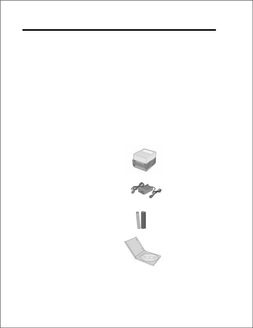
In addition to this manual, verify that you have the following materials when unpacking:
Printer
Power Module
AC Power Cord
Ribbon/Core
CD-ROM
Page 2-2 |
9001069A |
SATO CT Series Printers |
Section 2. Installation and Configuration
SETTING UP THE PRINTER
Consider the following when setting up the printer/
∙Locate a solid flat surface with adequate room to set the printer. Make sure the Power Module can be located so that the power connecting cable can be attached to the printer and the AC Power Cable can be connected to an AC power outlet.
∙The location should be near the host or computer terminal. The maximum distance is:
-10 feet for the Parallel interface. To fully utilize the capabilities of the printer, a cable meeting IEEE 1284 specifications must be used.
-18 feet for the optional Serial RS232 Interface.
-10 feet for the optional USB interface without hub.
-the optional 10baseT Ethernet Interface depends upon the LAN cabling.
∙For imformation on interfacing the printer to a host system, see Section 5. Interface Specifications.
Follow these steps to set up your printer:
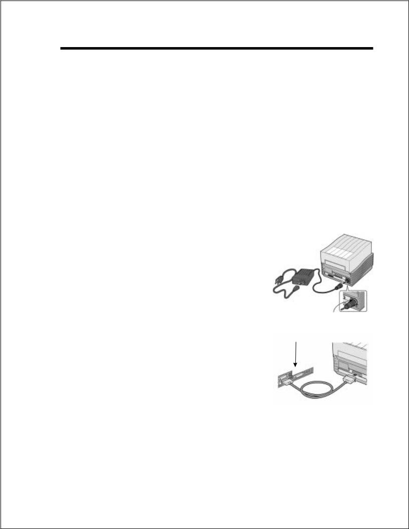
1.Make sure the power switch on the Operator Panel is in the OFF (0) position and place the Power Module in a safe and secure location, taking into consideration the location of the AC outlet and the host in relation to the printer.
2.Connect the Input Power connector to the printer. This connector is keyed and must be turned approximately 3/4 turn clockwise to secure it to the printer.
3.Connect the AC Power Cable to the proper AC Outlet supply.
4.Connect the interface cable to the host system. A parallel IEEE1284 interface cable must be used to realize the high data transfer rate of the printer’s parallel port. If an optional interface is installed, the appropriate cable should be used.
Input Power
Connector
Host I/F
Connector
5.Load the ribbon and media following the instructions in this section.
6.Configure the printer for label width and operating mode using the instructions in this section.
SATO CT Series Printers |
9001069A |
Page 2-3 |

Section 2. Installation and Configuration
7.Apply power to the printer by placing the AC Power switch in the ON (1) position.
8.Print a test label to verify the printer is set up and operating correctly.
Page 2-4 |
9001069A |
SATO CT Series Printers |

Section 2. Installation and Configuration
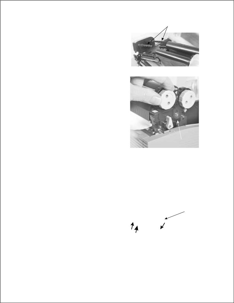
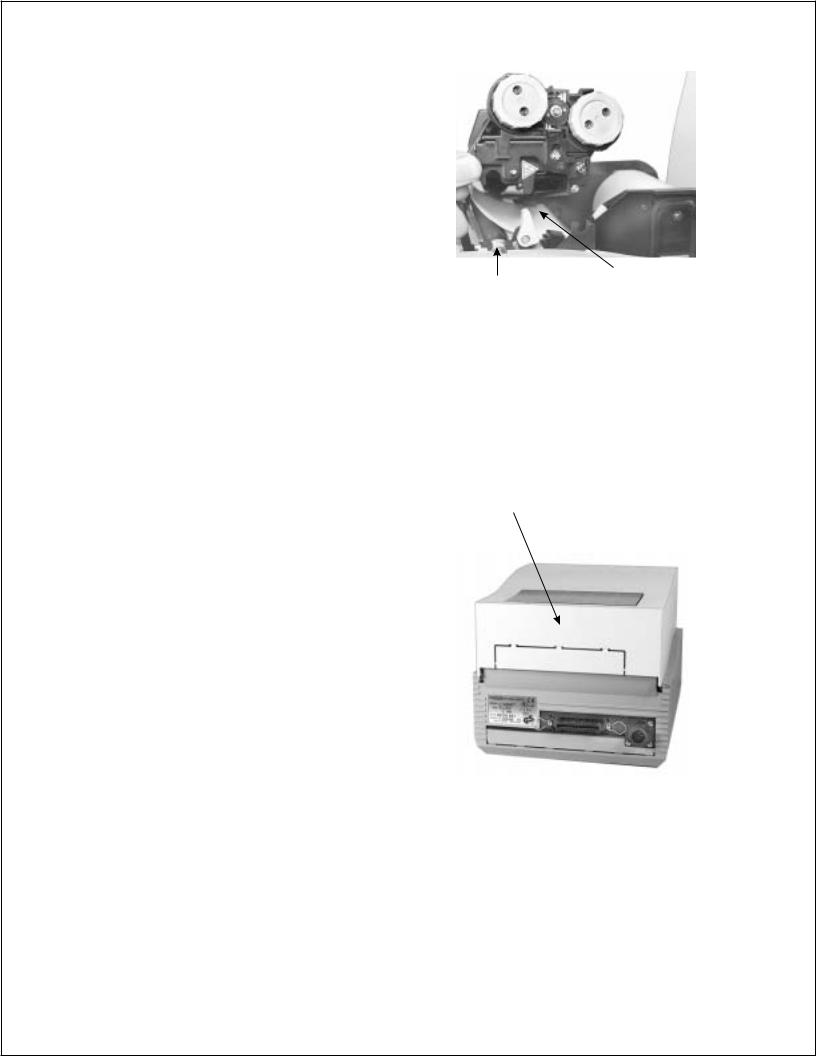
LOADING RIBBON (CT4XXTT only)
The SATO CT Series ribbons come shrink-wrapped with a 12" (305 mm)leader pre-attached to a takeup core. There are three widths of ribbon available for the CT Series printers; 4.3" (110 mm), 3" (76 mm) and 1.75" (45 mm).
1.Remove power from the printer.
2.Open the Top Cover by by pressing on cover the release points located on each side of the printer. This releases the cover latch and allows it to swing upward on the rear mounted hinge points.
3.Release the Print Head Assembly by pressing the Head Latch to the rear. This allows the assembly to rotate upward to the left allowing easy access for ribbon routing. Rotate the assembly until it is vertical.
4.Press down on the Ribbon Assembly Latch. This allows the Paper Roller to swing downward for ribbon routing.
5.Press down on the Ribbon Positioning button while simultaneously pulling upward on the Ribbon Spindle Unit. The Ribbon Spindle Unit should slide off.
6.Remove the shrink wrap from the ribbon and unwind approximately 6" of the leader. Press the Ribbon Supply core all the way onto the rear spindle of Ribbon Spindle Unit. Press the attached take-up core on the front spindle. Make sure each of the cores is fully seated on the spindles and there is enough ribbon leader to go down around the print head.
Head Latch
Ribbon
Position
Button 
Ribbon Supply
Spindle
Note: CT Series ribbons are wound face
(ink side) out. Make sure the dull (ink) Ribbon Take-Up Spindle
Ribbon
Spindle
Ribbon Ass’y
Latch
Head Latch
Ribbon Ass’y
Latch
Paper
Roller
Ribbon
Position
Button
SATO CT Series Printers |
9001069A |
Page 2-5 |
Section 2. Installation and Configuration
side of the ribbon will be in contact with the paper and the supply core is on the rear spindle.
7.Slide the Ribbon Spindle Unit over the Ribbon Drive Spindles until the Head Positioning Latch snaps into position. The first position corresponds to a 4.3" ribbon width. If you are using a narrower ribbon, press the Head Position Latch while sliding the Ribbon Spindle Unit to the correct position. There are three latch positions, one for a 4.3" wide ribbon, one for a 3" wide ribbon and one for a 1.75" wide ribbon.
8.The ribbon should be center justified (i.e., the center of the ribbon roll should be aligned with the center of the print head). If it is not, reposition the Ribbon Spindle Unit on the Drive Spindles until the Ribbon Position Latch is is in the correct position.
Ribbon Drive
Spindles
Ribbon Ass’y
Latch
9.Route the ribbon leader under the print head and between the Ribbon Assembly and the Paper Roller. Rotate the take-up spindle until the leader is completely wound onto the take-up core.
10.Push the Ribbon Assembly Latch to the up or locked position. Rotate the Paper Roller upward and latch it by pushing the Ribbon Assembly Latch into the upward position.
11.Latch the Print Head
Assembly in the closed |
Ribbon Path |
|
|
|
|
position by pushing |
|
|
downward on the “PUSH” |
|
|
tabs on both sides of the |
|
|
assembly until it latches in |
|
|
position. |
|
|
|
|
|
Page 2-6 |
9001069A |
SATO CT Series Printers |
Section 2. Installation and Configuration
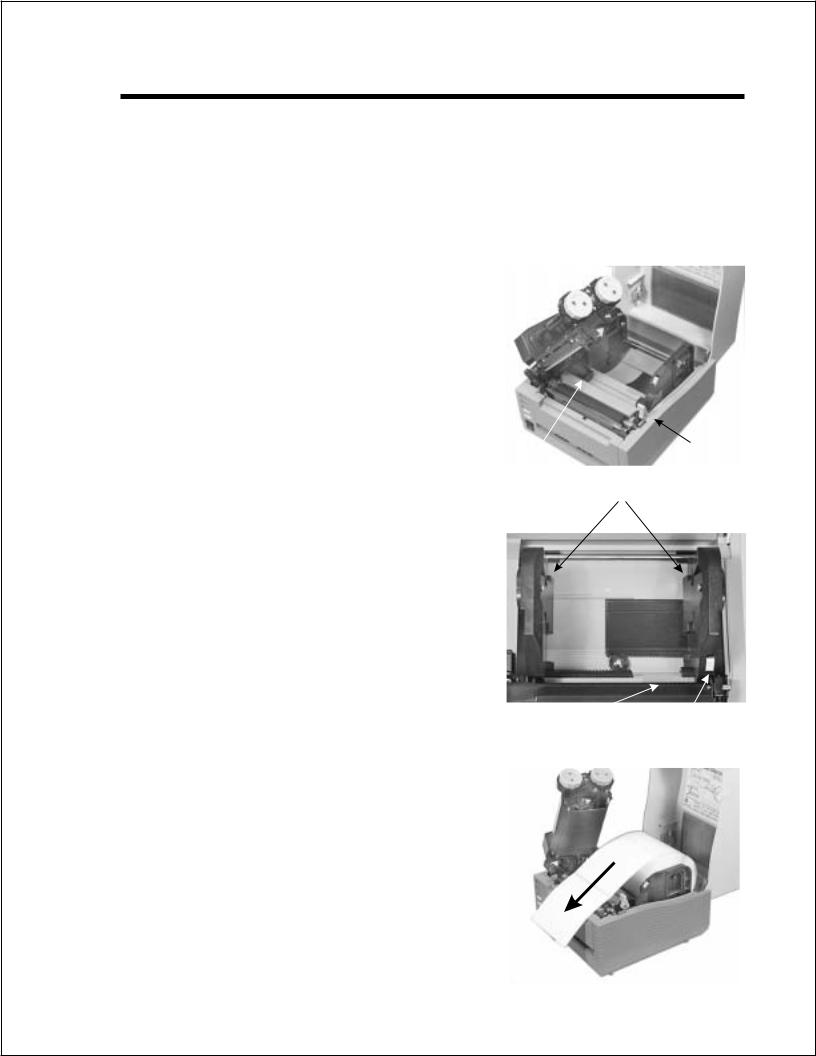
LOADING MEDIA
The CT Series printers can use die-cut labels, tag stock or continuous media. The media supply can be either roll or fanfold.
Roll Media
Roll media should be between 0.90" (23 mm) and 4.5" (115 mm) in width and wound face-out on a core with a minimum ID of 1.6" (40 mm).
1.Remove power from the printer by placing the Power Switch in the OFF (0) position.
2.Open the Top Cover by by pressing on cover release points located on
each side of the printer. This releases the cover latch and allows it to swing upward on the rear mounted hinge points.
3. Release the Print Head Assembly |
Paper |
Head |
|
Latch |
|||
by pressing the Head Latch to the |
Sensor |
||
|
|||
rear. This allows the assembly to |
|
Roll Holders |
|
rotate upward to the left allowing |
|
||
|
|
||
easy access for media routing. |
|
|
|
Rotate the assembly until it is |
|
|
|
vertical. |
|
|
4.With the Print Head Assembly in the up position, press the Paper Guide Release while adjusting the Paper Guides until they
allow a media roll to fit between |
|
|
|
them. A millimeter scale is molded |
|
|
|
into the case to provide a guide |
|
|
|
when making the adjustment. The |
Millimeter |
Paper Guide |
|
Paper Guides are center justified |
Scale |
||
Release |
|||
and interact with each other so that |
|
||
|
|
||
each moves an equal distance. |
|
|
5.Make sure the Roll Holders are in the released position. If they are not, lift up on each one and they will snap to the open position.
6.Unwind approximately 12" of label material from the roll. The labels should be wound face-out (printing side to the outside of the roll). Drop the roll in between the Paper Guides so that the labels
SATO CT Series Printers |
9001069A |
Page 2-7 |
Section 2. Installation and Configuration
come off the top of the roll. The Paper Guides will automatically position the Roll Holders to suspend the roll.
7.Route the label material through the
Paper Sensor Assembly and
over the Platen. Note that the |
|
|
|
Sensor is part of the left Label |
|
|
|
Roll Guide so that the Paper |
|
|
|
Sensor is always positioned in the |
|
|
|
same location relative to the left |
Platen |
Paper Sensor |
|
edge of the label. |
|||
|
|
8.Close and latch the Print Head Assembly.
9.Press the LINE key so that the printer is in the OFF LINE mode and then press the FEED key. The label should advance to the next index (label gap or eye-mark) position.
Fanfold Media
1.Place the fanfold media behind the printer with the printing surface up.
2.Open the Top Cover by by pressing on cover release points located on each side of the printer. This releases the cover latch and allows it to swing upward on the rear mounted hinge points.
Break Out for Fanfold Paper
3.Carefully break out the Fanfold Access Panel from the back of the Top Cover.
4.Release the Print Head Assembly by pressing the Head Latch to
the rear. This allows the assembly to rotate upward to the left allowing easy access for ribbon routing. Rotate the assembly until it is vertical.
5.With the Print Head Assembly in the up position, press the Paper Guide Release while adjusting the Paper Guides until they allow a media to fit between them. A millimeter scale is molded into the case to provide a guide when making the adjustment. The Paper Guides are center justified and interact with each other so that each moves an equal distance.
6.Route the label material through the Sensor Assembly and over the
Platen.
Page 2-8 |
9001069A |
SATO CT Series Printers |
Section 2. Installation and Configuration
7.Close and latch Print Head Assembly.
8.After loading the ribbon and media, it is recommended that you run a Test Print to make sure the labels and ribbon (for CX4XXTT only) are correctly loaded. See Section 2 for instructions on how to run test prints.
Route Paper under the Sensor
SATO CT Series Printers |
9001069A |
Page 2-9 |
Section 2. Installation and Configuration
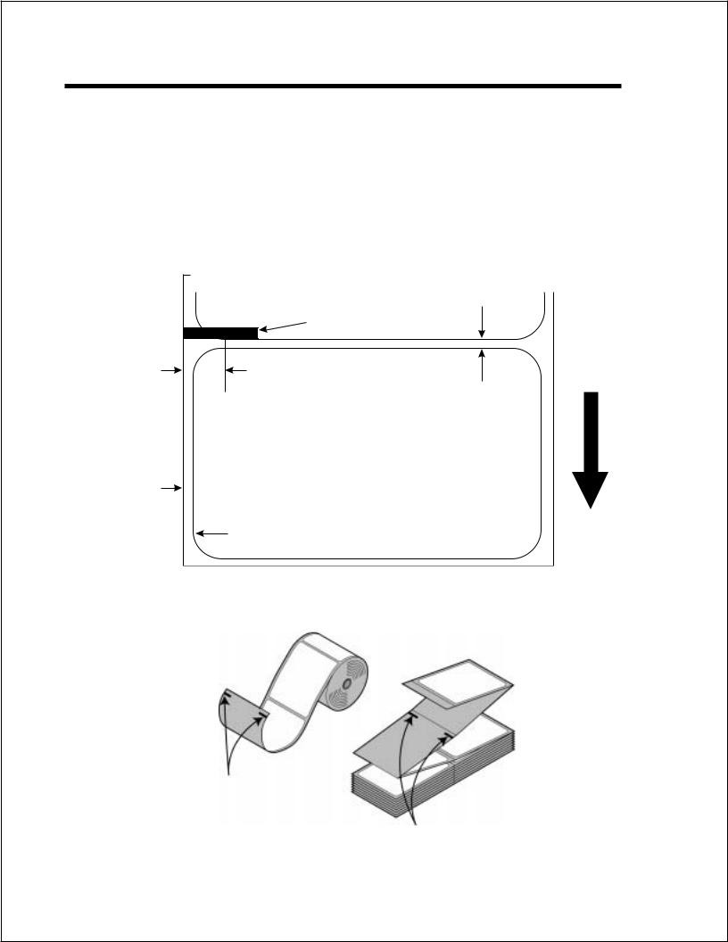
LABEL SENSING
The CT Series printers can use either label Gap (see-thru) or Eye-Mark (reflective) sensing. The Sensor Assembly is located on the left edge of the media and is automatically positioned by the Paper Guides.
The printer is shipped from the factory with the default sensing method set for label gap. The setting can be overridden by using the <ESC>IG command (Section 4) however it will be reset to the default when power is cycled. The default setting can be changed using the <ESC>PG command (Section 4) or the Printer Configuration Utility program on the CD-ROM.
Miminum Eye-Mark Size
.12 in (3 mm) W x .5 in. (12 mm) L
0.20" (5 mm) Eye-Mark Sensor 0.25" (6.3 mm) Gap Sensor
Backing
Paper Inside
Edge
Label Inside Edge
Label
Feed
Direction
Inter-Label Gap Min. 0.12" (3 mm) Max. 0.20" (5 mm)
CT Series Printer Label Sensor Positioning
Eye-Mark
Roll Paper
Eye-Mark
Fanfold Paper
Page 2-10 |
9001069A |
SATO CT Series Printers |
Section 2. Installation and Configuration
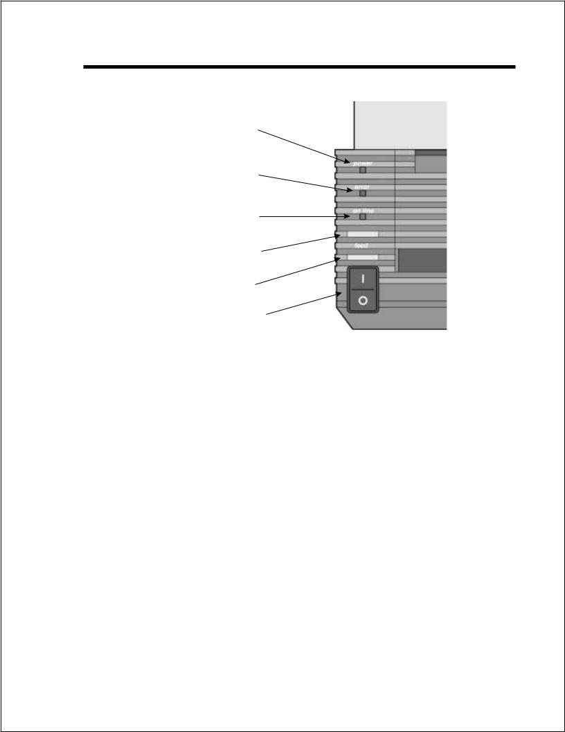
OPERATOR PANEL
The Operator Panel consists of three LED indicators and three switches.
POWER
LED
ERROR
LED
ON LINE
LED
|
ON LINE |
|
Key |
|
FEED |
|
Key |
|
POWER |
|
Switch |
POWER |
Green LED, illuminated when power is applied. |
ERROR |
Red LED, illuminated when there is a system fault |
|
such as an open print head. |
ON LINE |
Green LED, illuminated when the printer is ON LINE |
|
and ready to receive data. The printer is placed ON |
|
LINE and OFF LINE by toggling the ON LINE key. |
ON LINE KEY |
If the ONLINE LED is illuminated, pressing this switch |
|
will place the printer in the OFFLINE mode. Pressing |
|
the switch again will place the printer back in the |
|
ONLINE mode. If this switch is pressed while the |
|
printer is printing, the printing process is suspended. |
|
To resume printing, press this switch again. When the |
|
printer is ON LINE, it is ready to receive data from the |
|
host. When it is OFF LINE, the printer will not receive |
|
data from the host or print. |
FEED KEY |
Feeds one label when pressed in the OFFLINE mode. |
|
If this switch is held in the depressed position while |
|
power is applied, a printer status label will be printed. |
POWER |
A two position switch that applies power to the printer. |
|
When the “0" position is pressed, power is removed |
|
from the printer. When the ”1" position is pressed, |
|
power is applied to the printer. |
SATO CT Series Printers |
9001069A |
Page 2-11 |
Section 2. Installation and Configuration
REAR CONNECTOR PANEL
All of the printer cable connectors are located on the Rear Connector Panel.
Fanfold Paper
Slot
Optional I/F |
IEEE1284 Parallel |
Power |
|
Connector |
|||
IF Connector |
|||
Connector |
|||
|
|||
|
|
Power |
DC Power input to the printer. From Power Module. |
Parallel Interface |
IEEE1284 Parallel Interface Connector.. |
Optional Interface |
Connector for any installed optional interface. |
(if Installed) |
|
Fanfold Paper Slot |
Slot for fanfold paper. Panel must be removed to route |
|
fanfold paper into the printer. |
Page 2-12 |
9001069A |
SATO CT Series Printers |
Section 2. Installation and Configuration
CONFIGURATION PANEL
The Configuration Panel can be accessed by opening the Top Cover. It consists of an eight position DIP switch, three adjustment potentiometers and a seven segment LED Error display. Receptacles for connecting the Dispenser and Cutter options are also located on this panel.
Configuration |
|
Error |
Switch |
|
Display |
|
|
|
VR1
Potentiometer
Paper Handling
Print Mode
Head Check
VR1 Adjust
Hex Dump
I/F Select
CONFIGURATION SWITCH
An eight position DIP switch is utilized for setting the operating conditions of the printer.
Paper Handling (DSW1-3). Selects the method used for controlling the paper handling.
Continuous - Does not use the sensor for paper indexing. The paper movement will stop after all the label data has been printed.
Tear Off - Paper is fed out to the cut/tear off position after printing is complete. Before the next label is printed, the paper is pulled back in to the first print line position.
Cutter Mode - Enables the Cutter option if installed.
Dispenser Mode - Enables the Label Taken sensor if the Dispenser option is installed.
DSW1 |
DSW2 |
DSW3 |
SETTING |
|
|
Configuration Switch |
|
|
||||||
Off |
Off |
Off |
Continuous |
ON |
|
|
|
|
|
|
|
|
|
|
On |
Off |
Off |
Tear Off |
OFF |
|
|
|
|
|
|
|
|
|
|
|
|
|
|
|
|
|
|
|
||||||
|
|
|
|
|
|
|
|
|
|
|
|
|
||
Off |
On |
Off |
Cutter Mode |
|
|
|
|
|
|
|
|
|||
|
|
|
|
|
|
|
|
|
|
|||||
|
1 |
2 |
3 |
4 |
5 |
6 |
|
7 |
8 |
|||||
|
|
|
|
|
||||||||||
On |
On |
Off |
Dispenser |
|||||||||||
|
|
|
|
|
|
|
|
|
|
|||||
|
|
|
|
|
|
|
|
|
|
|
|
|
|
|
SATO CT Series Printers |
9001069A |
Page 2-13 |

Section 2. Installation and Configuration
Font/Graphic Download (DS1-3). Enables the downloading of fonts and/or graphics to printer memory.
|
|
|
|
|
|
Configuration Switch |
|
|
|||||
DSW1 |
DSW2 |
DSW3 |
SETTING |
ON |
|
|
|
||||||
|
|
|
|
|
|
|
|
|
|
|
|
|
|
Off |
On |
On |
Enable |
|
|
|
|
|
|
|
|
||
|
|
|
|
|
|
|
|
|
|
||||
|
|
|
|
OFF |
|
|
|
|
|
|
|
|
|
|
|
|
|
|
|
|
|
|
|
|
|
|
|
|
|
|
|
|
|
|
|
|
|
|
|
||
|
|
|
|
|
|
|
|
|
|
|
|
|
|
|
|
|
|
|
1 |
2 |
3 |
4 |
5 |
6 |
|
7 |
8 |
Print Method (DSW4). Selects Direct Thermal or Thermal Transfer print mode for a CT4XXTT printer.
|
|
|
|
Configuration Switch |
|
|||||
DSW4 |
SETTING |
ON |
|
|
||||||
|
|
|
|
|
|
|
|
|||
|
|
|
|
|
|
|
|
|||
Off |
Direct |
|
|
|
|
|
|
|
|
|
OFF |
|
|
|
|
|
|
|
|
||
|
|
|
|
|
|
|
|
|||
|
|
|
|
|
|
|
|
|
|
|
On |
Transfer |
|
|
|
|
|
|
|
||
|
|
|
1 |
2 |
3 |
4 |
5 |
6 |
7 |
8 |
|
|
|||||||||
|
|
|||||||||
Head Check (DSW5). When selected, the printer will check for head elements that are electrically malfunctioning.
|
|
|
|
Configuration Switch |
|
|||||
DSW5 |
SETTING |
ON |
|
|
||||||
|
|
|
|
|
|
|
|
|||
|
|
|
|
|
|
|
|
|||
Off |
Disabled |
|
|
|
|
|
|
|
|
|
OFF |
|
|
|
|
|
|
|
|
||
|
|
|
|
|
|
|
|
|||
|
|
|
|
|
|
|
|
|
|
|
On |
Enabled |
|
|
|
|
|
|
|
||
|
|
|
1 |
2 |
3 |
4 |
5 |
6 |
7 |
8 |
|
|
|||||||||
|
|
|||||||||
VR1 Potentiometer Function (DSW6). Select the function adjusted by VR1. When placed in the Off position, VR1 will adjust the pitch offset value over a range of +/- 3.75 mm. When placed in the On position, VR1 will adjust the print darkness range.
|
|
|
|
Configuration Switch |
|
|||||
DSW6 |
SETTING |
ON |
|
|
||||||
|
|
|
|
|
|
|
|
|||
|
|
|
|
|
|
|
|
|||
Off |
Pitch |
|
|
|
|
|
|
|
|
|
OFF |
|
|
|
|
|
|
|
|
||
|
|
|
|
|
|
|
|
|
|
|
On |
Darkness |
|
|
|
|
|
|
|
||
|
|
|
1 |
2 |
3 |
4 |
5 |
6 |
7 |
8 |
Hex Dump (DSW7). When ON, the printer will print out the hex value for each character received. When OFF, the printer will accept and process the data stream in a normal fashion.
|
|
|
|
Configuration Switch |
|
|||||
DSW7 |
SETTING |
ON |
|
|
||||||
|
|
|
|
|
|
|
|
|||
|
|
|
|
|
|
|
|
|||
Off |
Normal |
|
|
|
|
|
|
|
|
|
OFF |
|
|
|
|
|
|
|
|
||
|
|
|
|
|
|
|
|
|
|
|
On |
Hex |
|
|
|
|
|
|
|
||
|
|
|
|
|
|
|
|
|
||
|
|
|
1 |
2 |
3 |
4 |
5 |
6 |
7 |
8 |
Page 2-14 |
9001069A |
SATO CT Series Printers |
 Loading...