


 Loading...
CL608e/CL612e Printers
Service Manual
PN 9001079
Rev. B

SATO America, Inc.
10350-A Nations Ford Rd.
Charlotte, NC 28273 Main Phone: (704) 644-1650
Technical Support Hotline: (704) 644-1660
Fax: (704) 644-1661 http:\\www.satoamerica.com
ã Copyright 2002
SATO America, Inc.
The information supplied in this manual was current at time of publication. If you come across procedures that need clarification or find errors or have suggestions contact us at qc@satoamerica.com
Warning: This equipment complies with the requirements in Part 15 of FCC rules for a Class B computing device. Operation of this equipment in a residential area may cause unacceptable interference to radio and TV reception requiring the operator to take whatever steps are necessary to correct the interference.
All rights reserved. No part of this document may be reproduced or issued to third parties in any form whatever without the express permission of SATO America, Inc. The materials in this document are provided for general information and are subject to change without notice. SATO America, Inc. assumes no responsibility for any errors that may appear.
PN 9001079
Rev. B
SATO CL608e/CL612e Service Manual

Table of Contents
Section 1. Overview and Specifications |
Page |
|
1 |
Overview ........................................................................................................... |
1-1 |
2 |
Physical Characteristics .................................................................................. |
1-2 |
3 |
Printer Features ................................................................................................ |
1-3 |
4 |
Operation PanelDisplays ................................................................................. |
1-5 |
5 |
Components ..................................................................................................... |
1-7 |
6 |
Switches and Sensors ..................................................................................... |
1-8 |
7 |
Ribbon ............................................................................................................. |
1-10 |
8 |
Installation Considerations ........................................................................... |
1-10 |
9 |
Optional Accessories .................................................................................... |
1-10 |
10 Environment & Approvals ............................................................................. |
1-11 |
|
11 |
General Printer Specifications ...................................................................... |
1-11 |
12 |
Character Fonts ............................................................................................. |
1-14 |
13 Bar Codes ...................................................................................................... |
1-15 |
|
Section 2. |
Configuration |
|
1 |
Dip Switch Settings .......................................................................................... |
2-1 |
2 |
Default Settings ................................................................................................ |
2-7 |
3 |
LCD Panel Printer Configuration .................................................................... |
2-8 |
|
Normal Mode ................................................................................................. |
2-9 |
|
M8400 Compatible Mode ........................................................................... |
2-12 |
|
Advanced Mode .......................................................................................... |
2-13 |
|
Card Mode ................................................................................................... |
2-17 |
|
Service Mode .............................................................................................. |
2-25 |
|
Counters Mode ........................................................................................... |
2-31 |
|
Test Print Mode ........................................................................................... |
2-32 |
|
Default Setting Mode .................................................................................. |
2-33 |
|
Maintenance Mode ..................................................................................... |
2-34 |
|
Clear Non-Standard Protocol .................................................................... |
2-36 |
|
Download User Defined Protocol Codes ................................................. |
2-36 |
|
Hex Dump Mode ......................................................................................... |
2-37 |
|
Download Mode .......................................................................................... |
2-38 |
|
User Download Mode ................................................................................. |
2-39 |
4 |
Sample Test Labels ........................................................................................ |
2-40 |
Section 3. |
Interface Specifications |
|
1 |
Overview ........................................................................................................... |
3-1 |
2 |
Interface Types ................................................................................................. |
3-1 |
3 |
Receive Buffer .................................................................................................. |
3-3 |
4 |
IEEE 1284 Parallel Interface ............................................................................ |
3-4 |
5 |
Optional RS232C Serial Interface ................................................................... |
3-6 |
6 |
Universal Serial Bus (USB) Interface ............................................................. |
3-9 |
7 |
Local Area Network (LAN) Interface .............................................................. |
3-10 |
8 |
Bi-Directional Communications ..................................................................... |
3-10 |
9 |
Accessory (EXT) Connector ........................................................................... |
3-19 |
Section 4. Electrical Checks and Adjustments |
|
|
1 |
Overview ........................................................................................................... |
4-1 |
2 |
Steps Prior to Some Procedures .................................................................... |
4-2 |
3 |
DC Power Voltage Checks ............................................................................... |
4-3 |
4 |
Potentiometer Assignments & Adjustments ................................................. |
4-6 |
5a Pitch Offset Adjustment .................................................................................. |
4-8 |
|
PN 9001079 |
SATO CL608e/CL612e Service Manual |
i |
Rev. B |
|
|

Table of Contents
Section 4. Electrical Checks and Adjustments
5b Pitch Offset Adjustment .................................................................................. |
4-9 |
|
6 |
Label Gap Adjustment ................................................................................... |
4-10 |
7 |
Eye-Mark Adjustment .................................................................................... |
4-11 |
8 |
Feed/Backfeed Adjustment (Tear-Off) .......................................................... |
4-12 |
9 |
Feed/Backfeed Adjustment (Cutter) ............................................................. |
4-13 |
10 |
Feed/Backfeed Adjustment (Dispenser) ...................................................... |
4-14 |
11 |
Ribbon Sensor Verification ........................................................................... |
4-15 |
12 |
Ribbon Sensor Adjustment (Near End) ........................................................ |
4-16 |
13 |
LCD Display Adjustment ............................................................................... |
4-17 |
14 |
Print Darkness Adjustment ........................................................................... |
4-18 |
Section 5. Mechanical Adjustments
1 |
Overview ........................................................................................................... |
5-1 |
2 |
Ribbon Clutch Adjustments ............................................................................ |
5-2 |
3 |
Print Head Position Adjustment ..................................................................... |
5-5 |
4 |
Print Head Balance Adjustment ...................................................................... |
5-7 |
5 |
Ribbon Roller Adjustment ............................................................................... |
5-8 |
6 |
Feed Roller Adjustment (Label Tracking) ...................................................... |
5-9 |
7 |
Timing Belt Tension Adjustment ................................................................... |
5-11 |
8 |
Head Latch Adjustment ................................................................................. |
5-12 |
9 |
Notch/Gap Sensor Adjustment .................................................................... |
5-13 |
Section 6. Replacement Procedures
1 |
Overview .......................................................................................................... |
6-1 |
2 |
Replacing the Main Circuit Board .................................................................. |
6-2 |
3 |
Replacing the Fuses........................................................................................ |
6-7 |
4 |
Replacing the Power Supply ........................................................................... |
6-9 |
5 |
Replacing the Stepper Motor ........................................................................ |
6-12 |
6 |
Replacing the Timing Belts ........................................................................... |
6-13 |
7 |
Replacing the Print Head ............................................................................... |
6-16 |
8 |
Replacing the Platen ...................................................................................... |
6-19 |
9 |
Replacing the Ribbon Drive Clutch Washers .............................................. |
6-23 |
10 |
Replacing the Ribbon Motion Sensor .......................................................... |
6-27 |
11 |
Replacing the Paper End Switch (Micro-Switch) and the |
|
|
Bottom Half of the Notch/Gap and Eye-Mark Sensors ............................... |
6-30 |
12 |
Replacing the Top Half of the Notch/Gap Sensor ....................................... |
6-34 |
13 |
Replacing the Display Panel or Keyboard ................................................... |
6-37 |
Section 7. Factory Resets
1 |
Overview ........................................................................................................... |
7-1 |
2 |
Factory/Service Test Print ............................................................................... |
7-2 |
3 |
Clear Head Counters ........................................................................................ |
7-3 |
4 |
Clear Dispenser Counter ................................................................................. |
7-4 |
5 |
Clear Cutter Counter ........................................................................................ |
7-5 |
6 |
Clear EEPROM .................................................................................................. |
7-6 |
7 |
Sample Test Prints ........................................................................................... |
7-7 |
Section 8. Troubleshooting
1 |
Overview .......................................................................................................... |
8-1 |
2 |
Initial Checklist ................................................................................................ |
8-2 |
3 |
The IEEE 1284 Parallel Interface .................................................................... |
8-2 |
ii |
SATO CL608e/CL612e Service Manual |
PN 9001079
Rev. B

Table of Contents
Section 8. Troubleshooting
4 |
The RS232C Serial Interface ........................................................................... |
8-4 |
5 |
The Universal Serial BUS (USB) .................................................................... |
8-4 |
6 |
The LAN Ethernet Interface ............................................................................ |
8-5 |
7 |
Error Signals .................................................................................................. |
8-10 |
8 |
Troubleshooting Tables ................................................................................. |
8-11 |
9 |
Head Pattern Examples ................................................................................ |
8-15 |
10 |
Hex Dump Diagnostic Labels ....................................................................... |
8-17 |
Section 9. Optional Accessories |
|
|
1 |
Overview .......................................................................................................... |
9-1 |
2 |
Label Cutter Kit Installation ............................................................................ |
9-2 |
3 |
Label Dispenser Kit Installation ..................................................................... |
9-6 |
4 |
PCMCIA Memory Expansion Installation .................................................... |
9-15 |
5 |
Flash Memory Expansion Installation ......................................................... |
9-20 |
6 |
Real Time Clock Installation ......................................................................... |
9-22 |
Section 10. Parts List |
|
|
1 |
Overview ........................................................................................................ |
10-1 |
2 |
Base Cover Assembly ................................................................................... |
10-2 |
3 |
Frame Assembly ........................................................................................... |
10-11 |
4 |
Print Head Assembly .................................................................................. |
10-18 |
5 |
Ribbon Assembly ........................................................................................ |
10-22 |
6 |
Feed Roller Assembly ................................................................................. |
10-27 |
7 |
Main PCB Assembly .................................................................................... |
10-30 |
8 |
Interface Option ........................................................................................... |
10-31 |
9 |
Dispenser Assembly Option ...................................................................... |
10-32 |
10 |
Cutter Assembly Option ............................................................................. |
10-39 |
11 |
PCMCIA Memory Option ............................................................................. |
10-43 |
Index .............................................................................................................................. |
|
Index -1 |
PN 9001079 |
SATO CL608e/CL612e Service Manual |
iii |
Rev. B |
|
|

iv |
SATO CL608e/CL612e Service Manual |
PN 9001079
Rev. B

|
Section |
|
Overview and Specifications |
|
|
1.1 Overview
The SATO CL608e/CL612e Printers Service Manual provides information for installing and maintaining CL608e/CL612e Thermal Transfer printers. Step-by- step maintenance instructions are included in this manual with typical problems and solutions. It is recommended that you become familiar with each section in this manual before installing and maintaining the printer.
The major differences between the CL608e and the CL612 printers is the resolution of the head and label width. The CL608e with its 203 dpi head provides an economical labeling solution for most applications. It can print labels up to six inches wide. The CL612e provides a higher print resolution, 305 dpi to give laser-quality printing. It is useful when higher resolution is needed for detailed graphic images. It can print labels up to 6.5 inches wide.
The CL Series "e" printers use a subset of the standard SATO Command Language. The CL608e/CL612e share the same command set, the only differences are the allowable values representing the print positions on the label. These values are specified in "dots" and will vary depending upon the resolution of the printer and the amount of memory available for imaging the label. The allowable range for each printer is specified in a table for those command codes.
The sections in this manual cover the following:
·Section 1. Overview and Specifications
·Section 2. Configuration
·Section 3. Interface Specifications
·Section 4. Electrical Checks and Adjustments
·Section 5. Mechanical Adjustments
·Section 6. Replacement Procedures
·Section 7. Factory Resets
·Section 8. Troubleshooting
·Section 9. Optional Accessories
·Section 10. Parts list
PN 9001079 |
SATO CL608e/CL612e Service Manual |
Page 1-1 |
Rev. B |
|
|
Section 1. Overview and Specifications
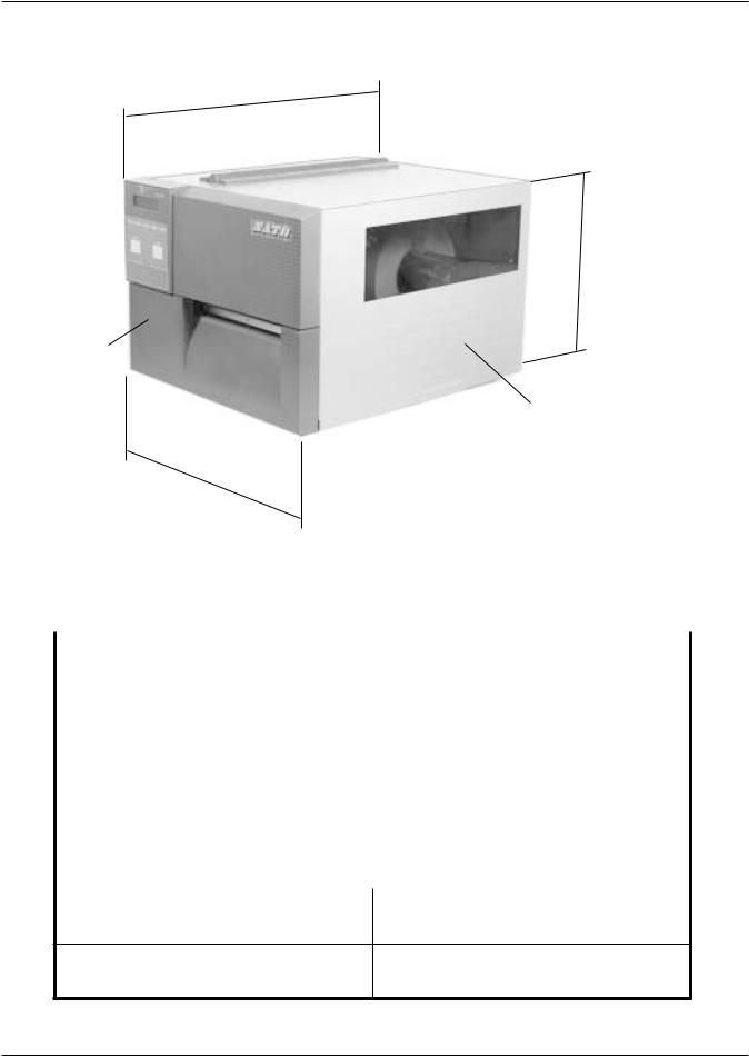
1.2 Physical Characteristics
Depth
Height
FRONT
ACCESS DOOR
Width
|
Dimensions |
|
CL608e |
CL612e |
|
|
|
|
|
|
|
|
Wide |
|
13.8 in. (352 mm) |
|
|
|
|
|
|
|
|
|
Deep |
|
16.9 in. (430 mm) |
|
|
|
|
|
|
|
|
|
High |
|
11.7 in. (298 mm) |
|
|
|
|
|
|
|
|
|
Weight |
|
41.9 lbs. (19 kg) |
|
|
|
|
|
|
|
|
|
|
Power Requirements |
|
|
|
|
|
|
|
|
|
|
Voltage |
|
115 -220 V (+/- 10%) |
|
|
|
|
50/60 Hz (+/- 1%) |
|
||
|
|
|
|
||
Power Consumption
50W idle
130W Operating
Page 1-2 |
SATO CL608e/CL612e Service Manual |
PN 9001079
Rev. B
Section 1. Overview and Specifications
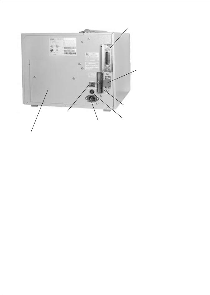
1.3 Printer Features
INTERFACE SLOT (SHOWN WITH CENTRONICS PARALLEL INTERFACE INSTALLED)
EXTERNAL
ACCESSORY
CONNECTOR
PCMCIA MEMORY
EXPANSION SLOT
POWER SWITCH
AC FUSE
AC POWER INPUT
CONNECTOR
COVER PLATE-REMOVE FOR
ACCESS TO FAN-FOLD SLOTS
Rear Panel
INTERFACE SLOT |
Slot to plug in an interface adapter. An adapter must be |
|
connected before the printer is operational. The adapter types |
|
available are: |
|
RS232C Serial I/F Module, DP-25P. |
|
IEEE1284 Parallel I/F Module, AMP 57-40360 |
|
Universal Serial Bus I/F Module |
|
Ethernet 10/100 BaseT I/F Module |
MEMORY CARD SLOT |
One slot for optional PCMCIA Memory Cards. |
EXT CONNECTOR |
External signal connector for Accessories, AMP 57-60140 |
POWER SWITCH |
Turns power On/Off |
AC FUSE |
Input power protection. Type 3A/250V. |
AC POWER INPUT |
Input 115V 50/60 Hz connector. Use the cable provided. |
PN 9001079 |
SATO CL608e/CL612e Service Manual |
Page 1-3 |
Rev. B |
|
|
Section 1. Overview and Specifications
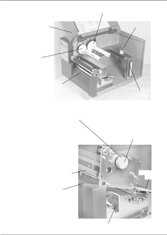
Printer Features
RIBBON UNWIND
SPINDLE
ACCESS DOOR
RIBBON REWIND
SPINDLE
LABEL TEAR
OFF PLATE
SWITCHES AND SENSORS Refer to Section 1.6
Adjust the Media Knob based on the media you have loaded. For media up to 2.3 inches wide, use the "1" position. For media between 2.3 and 4.6 inches wide, use the "2" position. For media wider than 4.6 inches wide, use the "3" position. If you use media narrower than 7 inches, using the wrong setting can void the print head warranty due to excessive pressure.
PRINT HEAD
ASSEMBLY
PLATEN
ROLLER
LABEL SUPPLY
GUIDE
MEDIA HOLDER
MEDIA KNOB
MEDIA HOLD
DOWN
HEAD LATCH
Page 1-4 |
SATO CL608e/CL612e Service Manual |
PN 9001079
Rev. B
Section 1. Overview and Specifications
1.4 Operation Panel/Displays
LCD DISPLAY
ADVISORY LED'S
FEED KEY
LINE KEY
COVER
|
|
|
|
ADVISORY LED'S |
|
|
|
|
|||
|
POWER |
Illuminated when power is on. |
|||
|
ONLINE |
Illuminated when printer is ready to receive data. Turn ON/OFF by |
|||
|
|
toggling the LINE key. |
|||
|
LABEL |
Illuminated when label supply is out. |
|||
|
RIBBON |
Illuminated when ribbon motion sensor does not detect any ribbon |
|||
|
|
motion. |
|||
|
ERROR |
Illuminated when there is a system fault such as an open print head. |
|||
LCD SCREEN |
|
2 LINE x 16 Character LCD display. Used for setting operational |
|||
|
|||||
|
|
|
|
parameters of the printer and displaying error conditions |
|
LINE KEY |
|
|
Momentary switch. Pressing this key toggles the printer between |
||
|
|
|
|
the on-line and off-line mode. When the printer is on-line, it is |
|
|
|
|
|
ready to receive data from the host. This key acts as a pause |
|
|
|
|
|
during a print job by taking the printer off-line. |
|
FEED KEY |
|
|
Momentary switch. Pressing this key feeds one blank label |
||
|
|
|
|
through the printer when it is off-line. When the printer is on-line, there is a |
|
|
|
|
|
user selectable option in the Service Mode (see page 2-28) to either print |
|
|
|
|
|
a copy of the previously printed label or feed a blank label. The default is |
|
|
|
|
|
to feed a blank label. |
|
PN 9001079 |
SATO CL608e/CL612e Service Manual |
Page 1-5 |
Rev. B |
|
|
Section 1. Overview and Specifications
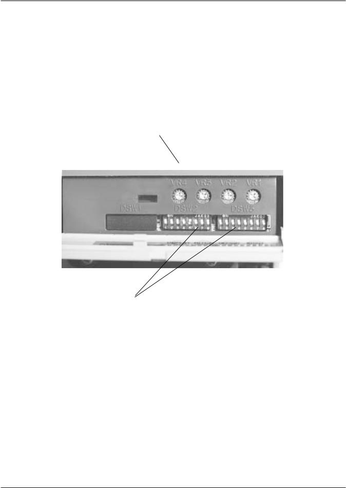
Operation Panel/Displays
|
POTENTIOMETERS |
||||||||||||||||||||||||||
VR1 (Print) |
To adjust print darkness (fine adjustment). |
||||||||||||||||||||||||||
VR2 (Offset) |
To adjust amount of back/forward feed for dispenser/cutter/tear-off |
||||||||||||||||||||||||||
|
bar position (+/- 3.75). |
||||||||||||||||||||||||||
VR3 (Pitch) |
To adjust home print position of the label (+/- 3.75 mm). |
||||||||||||||||||||||||||
VR4 (Display) |
To adjust the contrast of the LCD display. |
||||||||||||||||||||||||||
|
|
|
|
|
|
|
|
|
|
|
|
|
|
|
|
|
|
|
|
|
|
|
|
|
|
|
|
|
|
|
|
|
|
|
|
|
|
|
|
|
|
|
|
|
|
|
|
|
|
|
|
|
|
|
|
|
|
|
|
|
|
|
|
|
|
|
|
|
|
|
|
|
|
|
|
|
|
|
|
|
|
|
|
|
|
|
|
|
|
|
|
|
|
|
|
|
|
|
|
|
|
|
|
|
|
|
|
|
|
|
|
|
|
|
|
|
|
|
|
|
|
|
|
|
|
|
|
|
|
|
|
|
|
|
|
|
|
|
|
|
|
|
|
|
|
|
|
|
|
|
|
|
|
|
|
|
|
|
|
|
|
|
|
|
|
|
|
|
|
|
|
|
|
|
|
|
|
|
|
|
|
|
|
|
|
|
|
|
|
|
|
|
|
|
|
|
|
|
|
|
|
|
|
|
|
|
|
|
|
|
|
|
|
|
|
|
|
|
|
|
|
|
|
|
|
|
|
|
|
|
|
|
|
|
|
|
|
|
|
|
|
|
|
|
|
|
|
|
|
|
|
|
|
|
|
|
|
|
|
|
|
|
|
|
|
|
|
|
|
|
|
|
|
|
|
|
|
|
|
|
|
|
|
|
|
|
|
|
|
|
|
|
|
|
|
|
|
|
|
|
|
|
|
|
|
|
|
*DSW2 & DSW3 Dip Switches used to set operational parameters of printer. Refer to Section 2 for settings.
*NOTE: Optional RS232 Communication Card contains DSW1 switches which are configured when supplied with the printer.
Page 1-6 |
SATO CL608e/CL612e Service Manual |
PN 9001079
Rev. B
Section 1. Overview and Specifications
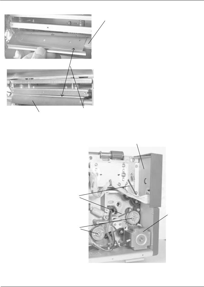
1.5 Components
PLATEN
PRINT HEAD
RIBBON GUIDE
PLATE
LCD BOARD AND
KB BOARD ON
BACKSIDE OF PANEL
TIMING
BELTS
STEPPER
MOTOR
PLATENS
PN 9001079 |
SATO CL608e/CL612e Service Manual |
Page 1-7 |
Rev. B |
|
|

Section 1. Overview and Specifications
Components
POWER SUPPLY UNIT
PLUG-IN INTERFACE
CARD - CENTRONICS
I/O SHOWN
1.6 Sensors and Switches
RIBBON SENSOR: This sensor is a motion detector that signals the printer when the ribbon supply is turning. This sensor is used for both the ribbon end and ribbon near end sensing.
HEAD LATCH LEVER: When the print head is opened, a micro switch is activated and the printer will stop printing. Error message will be displayed on the LCD operator panel.
Page 1-8 |
SATO CL608e/CL612e Service Manual |
PN 9001079
Rev. B
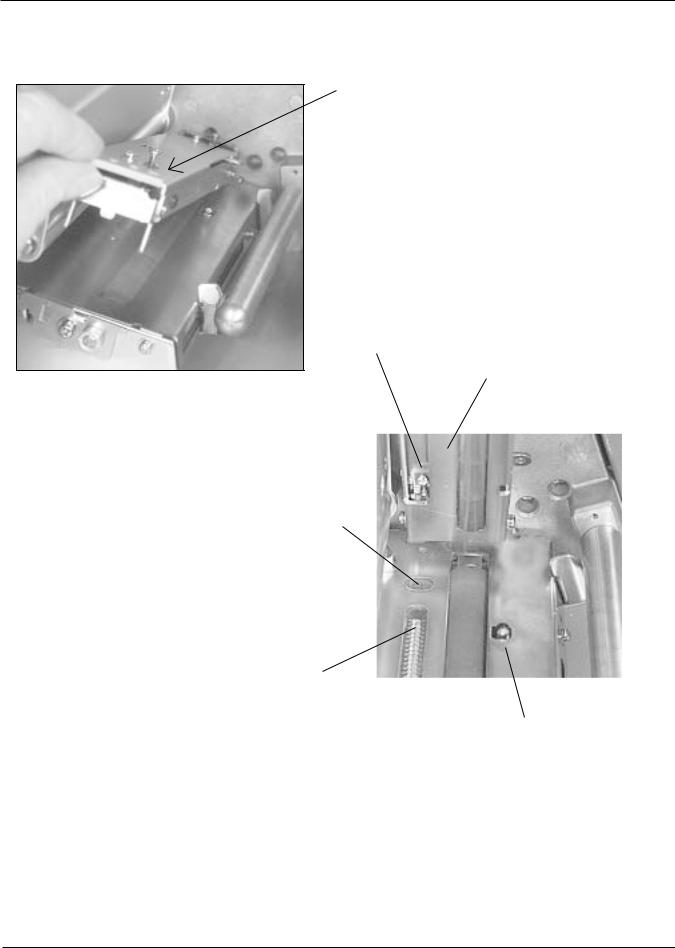
Section 1. Overview and Specifications
Switches and Sensors
MEDIA HOLD DOWN: Open by lifting up on the release tab underneath the green tab marked "PUSH". The Media Hold Down is spring loaded and will remain in the up position. Close by pushing down on the same green tab.
NOTCH/GAP SENSOR
(Top Half is adjustable) ( Refer to Section 5-10)
MEDIA HOLD DOWN
(Underside)
"EYE-MARK" SENSOR
(Fixed: Non adjustable)
NOTCH/GAP SENSOR LED ARRAY (Bottom Half is Non-adjustable)
LABEL OUT SENSOR: This micro switch is activated when media stock is out or when the Media Hold Down is in the up position. All printer operations stop, and an error message is displayed on the
LCD.
PN 9001079 |
SATO CL608e/CL612e Service Manual |
Page 1-9 |
Rev. B |
|
|

Section 1. Overview and Specifications
1.7 Ribbon
Use only SATO thermal transfer ribbons which were formulated expressly for use in all SATO printers. Use of other than approved ribbons may result in unsatisfactory print quality and/or damage to the print head and may void your warranty.
1.8 Installation Considerations
Printer operation can be affected by the printer environment. The location of the printer should be free from dust, humidity and sudden vibrations. To obtain optimum results from the printer, avoid locations influenced by:
•Direct or bright sunlight, since bright light will make the label sensor less responsive and may cause the label to be sensed incorrectly.
•Warm temperatures which can cause electrical problems within the printer. (See Section 1.10 Environment.
1.9 Optional Accessories
ACCESSORY |
CL608e/CL612e |
|
|
|
|
|
One slot for PCMCIA Memory Cards (up to 16 MB Flash or 4 |
|
Memory Expansion |
MB SRAM) and/or 4 MB internal Flash ROM. Can be used for |
|
graphic file storage, print buffer expansion, format storage and |
||
|
||
|
downloaded True Type fonts.* |
|
|
|
|
Calendar |
An internally mounted Date/Time chip that can be used to |
|
date/time stamp labels at the time of printing.* |
||
|
||
|
|
|
Label Cutter |
An internally mounted attachment allowing labels to be cut at |
|
specified internals. Controlled through programming.* |
||
|
||
|
|
|
|
Internal attachment allowing labels to peeled from backing for |
|
Label Dispenser |
immediate (on demand) application. Backing take-up mounted |
|
|
externally to rear of printer. |
|
|
|
|
Label Rewinder |
External option that rewinds labels onto a roll after they are |
|
printed. |
||
|
||
|
|
|
Parallel Interface |
IEEE1284 Parallel Interface Module |
|
|
|
|
Serial Interface |
High Speed Serial RS232 Interface Module |
|
|
|
|
Universal Serial I/F |
USB Interface Module |
|
|
|
|
Ethernet Interface |
10/100BaseT Interface Module |
|
|
|
|
|
Coax/Triax Interface Module. Coax I/F emulates an IBM 3287-2 |
|
Coax/Twinax Interface |
printer with a standard Type A BNC connector. Twinax I/F |
|
emulates IBM 5224, 5225, 5226 or 4214 printers with auto- |
||
|
||
|
terminate/cable-thru capabilities |
|
|
|
* Check with your software vendor to make sure these functions are supported.
Page 1-10 |
SATO CL608e/CL612e Service Manual |
PN 9001079
Rev. B

|
|
|
Section 1. Overview and Specifications |
|||||
|
1.10 Environment & Approvals |
|
|
|
|
|||
|
|
|
|
|
|
|
||
|
Environmental |
|
CL608e/CL612e |
|
|
|
||
|
|
|
|
|
|
|
||
|
Operating Temperature |
|
410 to 1040 F (50 to 400 C) |
|
|
|||
|
|
|
|
|
|
|
||
|
Storage Temperature |
|
-00 to 1040 F (-200 to 400 C) |
|
|
|||
|
|
|
|
|
|
|
||
|
Operating Humidity |
|
15-85% RH, non-condensing |
|
|
|||
|
|
|
|
|
|
|
||
|
Storage Humidity |
|
Max 90% RH, non-condensing |
|
|
|||
|
|
|
|
|
|
|
|
|
|
Electrostatic Discharge |
|
8KV |
|
|
|
|
|
|
|
|
|
|
|
|
|
|
|
Regulatory Approvals |
|
|
|
|
|
|
|
|
|
|
|
|
|
|
|
|
|
Safety |
|
UL, CSA |
|
|
|
|
|
|
|
|
|
|
|
|
|
|
|
RFI/EMI |
|
FCC Class A |
|
|
|
|
|
|
|
|
|
|
|
|
|
|
1.11 General Printer Specifications |
|
|
|
|
||||
|
|
|
|
|
|
|
||
|
Specification |
|
CL608e |
|
CL612e |
|
||
|
|
|
|
|
|
|
|
|
|
|
|
|
|
|
|
|
|
|
|
|
|
|
|
|||
|
Method |
|
Direct or Thermal Transfer |
|
||||
|
|
|
|
|
|
|||
|
Speed (User Selectable) |
|
4 to 8 ips - 100 to 200 mm/s |
|
||||
|
|
|
|
|
|
|
||
|
Print Module (Dot Size) |
|
.0049 in. - .125 mm |
|
.0033 in. - .083 mm |
|
||
|
|
|
|
|
|
|
||
|
Resolution |
|
203 dpi - 8 dpmm |
|
305 dpi - 12 dpmm |
|
||
|
|
|
|
|
|
|
||
|
Maximum Print Width |
|
6.0 in. - 152 mm |
|
6.5 in. - 164 mm |
|
||
|
|
|
|
|
|
|
||
|
Maximum Print Length |
|
49.2 in. - 1249 mm |
|
32.8 in. - 833 mm |
|
||
|
|
|
|
|
|
|
||
|
|
|
|
|
|
|
||
|
Specification |
|
CL608e |
|
CL612e |
|
||
|
|
|
|
|
|
|
|
|
|
Media |
|
|
|
|
|
|
|
|
|
|
|
|
|
|||
|
Minimum Width |
|
1.96 in. (50 mm) |
|
||||
|
|
|
|
|
|
|||
|
Minimum Length |
|
.78 in. (20 mm) |
|
||||
|
|
|
|
|
|
|||
|
Maximum Width |
|
7 in. (178 mm) |
|
||||
|
|
|
|
|
|
|||
|
Type |
|
Die Cut Labels, Fan-Fold, Tag Stock or Continuous |
|
||||
|
|
|
|
|
|
|||
|
Caliper |
|
.010 in. (.25 mm) |
|
||||
|
|
|
|
|
|
|||
|
Roll OD (max) |
|
8.6 in. (218 mm), Face-in Wind |
|
||||
|
|
|
|
|
|
|||
|
Core ID (min) |
|
1.5 in. (38 mm) |
|
||||
|
|
|
|
|
|
|||
|
Core ID (Recommended) |
|
3 in. (76 mm) |
|
||||
|
|
|
|
|
|
|
|
|
PN 9001079 |
SATO CL608e/CL612e Service Manual |
Page 1-11 |
Rev. B |
|
|

Section 1. Overview and Specifications
General Printer Specifications
Specification |
CL608e |
|
CL612e |
|
|
|
|
Sensing |
|
|
|
|
|
|
|
Transmissive See-thru |
|
Movable |
|
|
|
|
|
Reflective Eye-Mark |
|
Fixed |
|
|
|
|
|
Continuous Form |
|
Sensor not used |
|
|
|
|
|
Ribbon |
|
|
|
|
|
|
|
Maximum Width |
|
6.75 in. (172 mm) |
|
|
|
|
|
Length |
|
1345 ft. (410 m) |
|
|
|
|
|
Thickness |
4.5 micron, Face in Wind |
||
|
|
|
|
Controls and Signals |
|
|
|
|
|
|
|
On-Line LED |
|
Green |
|
|
|
|
|
Power LED |
|
Green |
|
|
|
|
|
Media Out LED |
|
Red |
|
|
|
|
|
Ribbon Out LED |
|
Red |
|
|
|
|
|
Error LED |
|
Red |
|
|
|
|
|
LCD Panel |
2 Line x 16 Character |
||
|
|
|
|
On/Off-Line Switch |
|
Front Panel |
|
|
|
|
|
Label Feed Switch |
|
Front Panel |
|
|
|
|
|
Power On/Off Switch |
|
Rear Panel |
|
|
|
|
|
Potentiometer Adjustments |
|
|
|
|
|
|
|
Print Darkness |
|
Front Panel |
|
|
|
|
|
Pitch |
|
Front Panel |
|
|
|
|
|
Offset |
|
Front Panel |
|
|
|
|
|
Display |
|
Front Panel |
|
|
|
|
|
Page 1-12 |
SATO CL608e/CL612e Service Manual |
PN 9001079
Rev. B

|
|
|
Section 1. Overview and Specifications |
|||
General Printer Specifications |
|
|
|
|
||
|
|
|
|
|
|
|
|
Specification |
CL608e |
|
CL612e |
|
|
|
|
|
|
|
|
|
|
Interface Modules |
|
|
|
|
|
|
|
|
|
|
|
|
|
Parallel |
|
IEEE 1284 Parallel |
|
||
|
|
|
|
|
||
|
|
RS232C (9600 to 57,600 bps) |
|
|||
|
Serial |
RS422/485 (9600 to 57,600 bps) |
|
|||
|
|
Hardware Flow Control (Ready/Busy) |
|
|||
|
Serial Protocol |
Software Flow Control (X-On/X-Off) |
|
|||
|
|
Bi-directional Status 2,3 or 4 |
|
|||
|
|
|
|
|
|
|
|
Universal Serial Bus |
|
USB Version 1.1 |
|
||
|
|
|
|
|
|
|
|
Ethernet |
|
10/100BaseT |
|
||
|
|
|
|
|
|
|
|
Data Transmission |
|
ASCII Format |
|
||
|
|
|
|
|
|
|
|
Processing |
|
|
|
|
|
|
|
|
|
|
|
|
|
CPU |
|
32 Bit RISC |
|
||
|
|
|
|
|
|
|
|
Flash ROM |
|
2 MB |
|
||
|
|
|
|
|
|
|
|
SDRAM |
|
16 MB |
|
||
|
|
|
|
|
|
|
|
Receive Buffer |
|
2.95 MB |
|
||
|
|
|
|
|
|
|
|
Optional Flash ROM |
|
4 MB |
|
||
|
|
|
|
|
||
|
Optional PCMCIA Memory |
Up to 16 MB Flash or 4 MB SRAM |
|
|||
|
|
|
|
|
|
|
PN 9001079 |
SATO CL608e/CL612e Service Manual |
Page 1-13 |
Rev. B |
|
|

Section 1. Overview and Specifications
1.12 Character Fonts
Specification |
CL608e |
CL612e |
|
|
|
Matrix Fonts |
|
|
|
|
|
U Font |
(5 dots W x 9 dots H) |
|
|
|
|
S Font |
(8 dots W x 15 dots H) |
|
|
|
|
M Font |
(13 dots W X 20 dots H) |
|
|
|
|
XU Font |
(5 dots W x 9 dots H) Helvetica |
|
|
|
|
XS Font |
(17 dots W x 17 dots H) Univers Condensed Bold |
|
|
|
|
XM Font |
(24 dots W x 24 dots H) Univers Condensed Bold |
|
|
|
|
OA Font |
(15 dots W x 22 dots H) OCR-A |
(22 dots W x 33 dots H) OCR-A |
|
|
|
OB Font |
(20 dots W x 24 dots H) OCR-B |
(30 dots W x 36 dots H) OCR-B |
|
|
|
Auto Smoothing Fonts |
|
|
|
|
|
WB |
WB Font (18 dots W x 30 dots H) |
|
|
|
|
WL |
WL Font (28 dots W x 52 dots H) |
|
|
|
|
XB |
XB Font (48 dots W x 48 dots H) Univers Condensed Bold |
|
|
|
|
XL |
XL Font (48 dots W x 48 dots H) Sans Serif |
|
|
|
|
Vector Font |
|
|
|
|
|
|
Proportional or Fixed Spacing |
|
|
Font Size 50 x 50 dots to 999 x 999 dots |
|
|
Helvetica, 10 Font Variations |
|
|
|
|
AGFA® Raster Fonts |
|
|
|
|
|
A Font |
CG Times, 8 to 72 pt |
|
|
|
|
B Font |
CG Triumvirate, 8 to 72 pt |
|
|
|
|
Downloadable Fonts |
|
|
|
|
|
|
Bit Mapped TrueType Fonts with Utility Program |
|
|
|
|
Character Control |
|
|
|
|
|
|
Expansion up to 12 X in either the X or Y coordinates |
|
|
Character Pitch control |
|
|
Line Space control |
|
|
Journal Print facility |
|
|
00, 900, 1800 and 2700 Rotation |
|
|
|
|
Page 1-14 |
SATO CL608e/CL612e Service Manual |
PN 9001079
Rev. B
|
|
|
Section 1. Overview and Specifications |
|||
|
1.13 Bar Codes |
|
|
|
|
|
|
Specification |
CL608e |
|
CL612e |
|
|
|
|
|
|
|
|
|
|
Symbologies |
|
|
|
|
|
|
|
|
|
|
||
|
|
Bookland (UPC/EAN Supplemental) |
|
|||
|
|
|
EAN-8, EAN-13 |
|
||
|
|
|
CODABAR |
|
||
|
|
|
Code 39 |
|
||
|
|
|
Code 93 |
|
||
|
|
|
Code 128 |
|
||
|
|
|
Interleaved 2 of 5 |
|
||
|
|
|
Industrial 2 of 5 |
|
||
|
|
|
Matrix 2 of 5 |
|
||
|
|
|
MSI |
|
||
|
|
|
POSTNET |
|
||
|
|
|
UCC/EAN-128 |
|
||
|
|
|
UPC-A and UPC-E |
|
||
|
|
|
Data Matrix |
|
||
|
|
|
Maxicode |
|
||
|
|
|
PDF417 |
|
||
|
|
|
|
|
||
|
Ratios |
1:2, 1:3, 2:5 User definable bar widths |
|
|||
|
|
|
|
|
||
|
Bar Height |
4 to 600 dots, User programmable |
|
|||
|
|
|
|
|
|
|
|
Rotation |
|
00, 900, 1800 and 2700 |
|
||
|
|
|
|
|
|
|
|
Other Features |
|
|
|
|
|
|
|
|
|
|
||
|
Sequential Numbering |
Sequential numbering of both numerics and bar codes |
|
|||
|
|
|
|
|
||
|
Custom Characters |
RAM storage for special characters |
|
|||
|
|
|
|
|
||
|
Graphics |
Full dot addressable graphics, SATO Hex/Binary, .BMP or .PCX |
|
|||
|
|
formats |
|
|
||
|
|
|
|
|||
|
|
|
|
|
||
|
Form Overrlay |
Form overlay for high-speed editing of complex formats |
|
|||
|
|
|
|
|
|
|
PN 9001079 |
SATO CL608e/CL612e Service Manual |
Page 1-15 |
Rev. B |
|
|

Section 1. Overview and Specifications
Page 1-16 |
SATO CL608e/CL612e Service Manual |
PN 9001079
Rev.B
Section
Configuration |
2 |
|
|
||
|
|
|
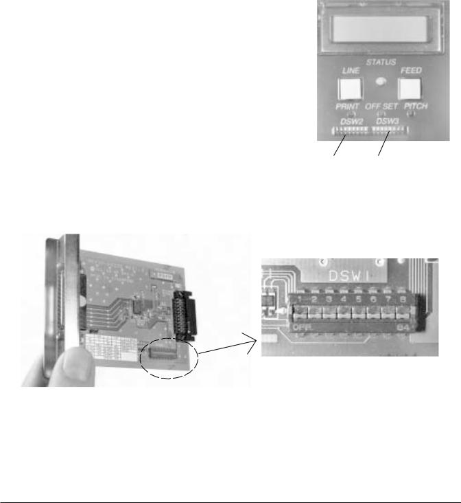
2.1 Dip Switch Settings
Two DIP switches (DSW2 & DSW3) are located inside the Front Access Door. These switches can be used to set:
•Thermal transfer or direct thermal mode
•Head Check Mode
•Hex Dump Mode
•Label sensor enable/disable
•Single Job or Multi-Job Receive Buffer
•Operation Mode
DIP SWITCHES
In addition, a third DIP switch (DSW1) is located on the optional RS232 Serial Adapter card and is used to set the RS232C transmit/receive parameters.
DSW1
Each switch is an eight section toggle switch. The On position is always to the top. To set the switches, first power the unit Off, then position the DIP switches. Finally after placing the switches in the desired positions, power the printer back on. The switch settings are read by the printer electronics during the power-up sequence. They will not become effect until the power is cycled.
PN 9001079 |
SATO CL608e/CL612e Service Manual |
Page 2-1 |
Rev. B |
|
|
Section 2. Configuration
Dip Switch Settings
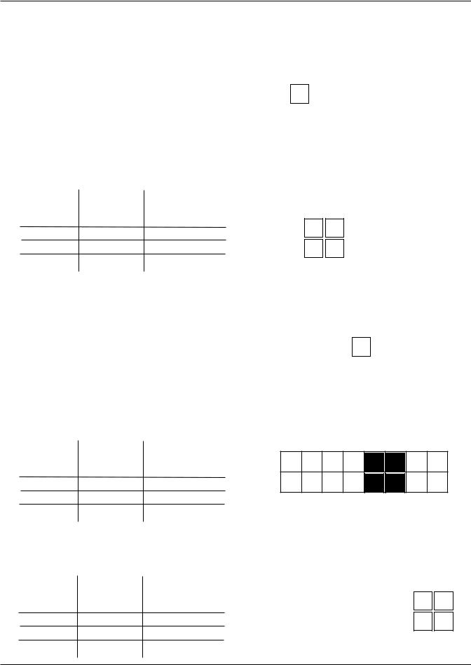
RS232 Transmit/Receive Setting (located on RS232 I/F Module)
Data Bit Selection (DSW1-1): This switch sets the printer to receive either 7 or 8 |
|
|
||||||||||||||||||||||||||||
data bits for each byte transmitted. |
|
|
|
|
|
|
|
|
|
|
|
|
DSW1 |
|
|
|
|
|
|
|||||||||||
|
|
|
|
|
|
|
|
|
|
|
|
|
|
|
|
|
|
|
|
|
|
|
|
|
|
|||||
|
|
|
DSW1-1 |
|
SETTING |
|
|
ON |
|
|
|
|
|
|
|
|
|
|
|
|
|
|
|
|
|
|
|
|||
|
|
|
|
|
|
|
|
|
|
|
|
|
|
|
|
|
|
|
|
|
|
|
|
|
|
|
|
|
|
|
|
|
|
Off |
|
8 data bits |
|
|
OFF |
|
|
|
|
|
|
|
|
|
|
|
|
|
|
|
|
|
|
|
|||
|
|
|
|
|
|
|
|
|
|
|
|
|
|
|
|
|
|
|
|
|
|
|
|
|
||||||
|
|
|
|
|
|
|
|
|
|
|
|
|
|
|
|
|
|
|
|
|
||||||||||
|
|
|
|
|
|
|
|
|
|
|
|
|
|
|
|
|
|
|
|
|
|
|
|
|
|
|
||||
|
|
|
|
|
|
|
|
|
|
|
|
|
|
|
|
|
|
|
|
|
|
|
|
|
|
|
|
|
|
|
|
|
|
On |
|
7 data bits |
|
|
1 |
|
2 |
|
3 |
4 |
5 |
|
6 |
|
7 |
8 |
|||||||||||
|
|
|
|
|
|
|
|
|
|
|
|
|||||||||||||||||||
Parity Selection (DSW1-2, DSW1-3): These switches select the type of parity used |
|
|
||||||||||||||||||||||||||||
for error detection. |
|
|
|
|
|
|
|
|
|
|
|
|
|
|
|
|
|
|
|
|
|
|
|
|
||||||
|
|
|
|
|
|
|
|
|
|
|
|
|
|
|
|
|
|
|
|
|
|
|
|
|
||||||
|
DSW1-2 DSW1-3 |
SETTING |
|
|
|
|
|
|
|
|
|
|
|
DSW1 |
|
|
|
|
|
|
||||||||||
|
|
|
|
|
|
|
|
|
|
|
|
|
|
|
|
|
|
|
|
|
|
|
|
|
||||||
|
|
|
Off |
Off |
None |
ON |
|
|
|
|
|
|
|
|
|
|
|
|
|
|
|
|
||||||||
|
|
|
|
|
|
|
|
|
|
|
|
|
|
|
|
|
|
|
|
|
|
|
|
|||||||
|
|
|
|
|
|
|
|
|
|
|
|
|
|
|
|
|
|
|
|
|
|
|
|
|||||||
|
|
|
Off |
On |
Even |
|
|
|
|
|
|
|
|
|
|
|
|
|
|
|
|
|
|
|
|
|
||||
|
|
|
OFF |
|
|
|
|
|
|
|
|
|
|
|
|
|
|
|
|
|
|
|
|
|
||||||
|
|
|
On |
Off |
Odd |
|
|
|
|
|
|
|
|
|
|
|
|
|
|
|
|
|
|
|
|
|
||||
|
|
|
On |
On |
Not Used |
|
|
|
|
|
|
|
|
|
|
|
|
|
|
|
|
|
|
|
|
|
|
|||
|
|
|
1 |
|
2 |
|
|
3 |
|
|
4 |
|
5 |
|
6 |
|
7 |
|
8 |
|
||||||||||
|
|
|
|
|
|
|
|
|
|
|
|
|
|
|
|
|
|
|||||||||||||
|
|
|
|
|
|
|
|
|
|
|
|
|
|
|
|
|
|
|||||||||||||
Stop Bit Selection (DSW1-4): Selects the number of stop bits to end each byte |
|
|
|
|
||||||||||||||||||||||||||
transmission. |
|
|
|
|
|
|
|
|
|
|
|
|
|
|
|
|
DSW1 |
|
|
|
|
|
|
|||||||
|
|
|
|
|
|
|
|
|
|
|
|
|
|
|
|
|
|
|
|
|
|
|
|
|
|
|||||
|
|
|
DSW1-4 |
|
SETTING |
|
|
ON |
|
|
|
|
|
|
|
|
|
|
|
|
|
|
|
|
|
|
|
|
||
|
|
|
|
|
|
|
|
|
|
|
|
|
|
|
|
|
|
|
|
|
|
|
|
|
|
|||||
|
|
|
|
|
|
|
|
|
|
|
|
|
|
|
|
|
|
|
|
|
|
|
|
|
|
|
|
|
||
|
|
|
Off |
|
1 Stop Bit |
|
|
OFF |
|
|
|
|
|
|
|
|
|
|
|
|
|
|
|
|
|
|
|
|
||
|
|
|
|
|
|
|
|
|
|
|
|
|
|
|
|
|
|
|
|
|
|
|||||||||
|
|
|
|
|
|
|
|
|
|
|
|
|
|
|
|
|
|
|
|
|
|
|||||||||
|
|
|
On |
|
2 Stop Bits |
|
|
|
|
|
|
|
|
|
|
|
|
|
|
|
|
|
|
|
|
|
|
|
||
1 |
2 |
3 |
4 |
5 |
6 |
7 |
8 |
|||||||||||||||||||||||
|
|
|
|
|
|
|
|
|||||||||||||||||||||||
Baud Rate Selection (DSW1-5, DSW1-6): port.
DSW1-5 DSW1-6 |
SETTING |
|
|
|
|
Off |
Off |
9600 |
Off |
On |
19200 |
On |
Off |
38400 |
On |
On |
57600 |
|
|
|
Selects the data rate (bps) for the RS232
DSW1
ON
OFF
1 |
2 |
3 |
4 |
5 |
6 |
7 |
8 |
Protocol Selection (DSW1-7, DSW1-8): Selects the flow control and status reporting protocols.
(* Will select protocol Bi-Com 2 for M-8400 if DSW2-8 is ON)
DSW1-7 |
DSW1-8 |
SETTING |
|
|
|
|
DSW1 |
||||||
|
|
|
ON |
|
|
|
|
|
|
|
|
|
|
Off |
Off |
Rdy/Bsy |
|
|
|
|
|
|
|
|
|
||
|
|
|
|
|
|
|
|
|
|
||||
Off |
On |
Xon/Xoff |
OFF |
|
|
|
|
|
|
|
|
|
|
|
|
|
|
|
|
|
|
|
|||||
On |
Off |
Bi-Com 3 |
|
|
|
|
|
|
|
|
|
|
|
1 2 3 4 5 6 7 8 |
|||||||||||||
On |
On |
Bi-Com 4* |
|||||||||||
|
|
|
|
|
|
|
|
|
|
|
|
|
|
Page 2-2 |
SATO CL608e/CL612e Service Manual |
PN 9001079
Rev. B

Section 2. Configuration
Dip Switch Settings
Printer Set up
Print Mode Selection (DSW2-1): Selects between direct thermal printing on thermally sensitive paper and thermal transfer printing using a ribbon.
|
|
|
|
|
|
|
|
|
|
|
|
|
|
|
DSW2 |
|
|
|
|
|
|
|||
|
DSW2-1 |
|
SETTING |
|
|
|
|
|
|
|
|
|
|
|
|
|
|
|
|
|||||
|
|
ON |
|
|
|
|
|
|
|
|
|
|
|
|
|
|
|
|
|
|
||||
|
Off |
|
Transfer |
OFF |
|
|
|
|
|
|
|
|
|
|
|
|
|
|
|
|
|
|
||
|
|
|
|
|
|
|
|
|
|
|
|
|
|
|
|
|
|
|
|
|||||
|
|
|
|
|
|
|
|
|
|
|
|
|
|
|
|
|
|
|||||||
|
On |
|
Direct Therm |
|
|
|
|
|
|
|
|
|
|
|
|
|
|
|
|
|
|
|
|
|
1 |
|
2 |
|
|
3 |
4 |
|
5 |
|
6 |
|
7 |
|
8 |
|
|||||||||
|
|
|
|
|
|
|
|
|
|
|
|
|
||||||||||||
Sensor Type Selection (DSW2-2): Selects between the use of a label gap or a |
|
|
|
|
||||||||||||||||||||
reflective Eye-Mark. |
|
|
|
|
|
|
|
|
|
|
|
|
|
|
|
|
|
|
|
|
||||
|
|
|
|
|
|
|
|
|
|
|
|
|
|
DSW2 |
|
|
|
|
|
|
||||
|
DSW2-2 |
SETTING |
|
|
|
|
|
|
|
|
|
|
|
|
|
|
|
|
||||||
|
|
|
|
|
|
|
|
|
|
|
|
|
|
|
|
|
|
|
|
|||||
ON |
|
|
|
|
|
|
|
|
|
|
|
|
|
|
|
|
|
|
|
|||||
|
Off |
Gap |
|
OFF |
|
|
|
|
|
|
|
|
|
|
|
|
|
|
|
|
|
|
|
|
|
|
|
|
|
|
|
|
|
|
|
|
|
|
|
|
|
|
|
||||||
|
|
|
|
|
|
|
|
|
|
|
|
|
|
|
|
|
|
|
|
|
|
|||
|
On |
Eye-Mark |
|
|
|
|
|
|
|
|
|
|
|
|
|
|
|
|
|
|
|
|
|
|
1 |
|
2 |
|
|
3 |
4 |
|
5 |
|
6 |
|
7 |
|
8 |
|
|||||||||
|
|
|
|
|
|
|
|
|
|
|
|
|
||||||||||||
|
|
|
|
|
|
|
|
|
|
|
|
|
||||||||||||
Head Check Selection (DSW2-3): When selected, the printer will check for head elements that are electrically malfunctioning.
|
|
|
|
|
|
|
|
|
|
|
|
|
|
DSW2 |
|
|
|
|
|
|
DSW2-3 |
|
SETTING |
|
ON |
|
|
|
|
|
|
|
|
|
|
|
|
|
|
|
|
|
|
|
|
|
|
|
|
|
|
|
|
|||
|
|
|
|
|
|
|
|
|
|
|
|
|
|
|
|
|
|
|
|
|
Off |
|
Disable |
|
OFF |
|
|
|
|
|
|
|
|
|
|
|
|
|
|
|
|
|
|
|
|
|
|
|
|
|
||||||
|
|
|
|
|
|
|
|
|
|
|
|
|
||||||
|
|
|
|
|
|
|
|
|
|
|
|
|
|
|
|
|
|
|
|
|
On |
|
Enable |
|
|
|
|
|
|
|
|
|
|
|
|
|
|
1 |
|
2 |
3 |
|
4 |
5 |
6 |
7 |
8 |
|||||||||
|
|
|
|
|
|
|
||||||||||||
Hex Dump Selection (DSW2-4): Selects Hex Dump mode. |
|
|
|
|
|
|
|
|
|
|||||||||
|
|
|
|
|
|
|
|
|
|
|
|
|
|
DSW2 |
|
|
|
|
|
|
DSW2-4 |
|
SETTING |
|
ON |
|
|
|
|
|
|
|
|
|
|
|
|
|
|
|
|
|
|
|
|
|
|
|
|
|
|
|
||||
|
|
Off |
|
Disable |
|
OFF |
|
|
|
|
|
|
|
|
|
|
|
|
|
|
|
|
|
|
|
|
|
|
|
|
|||||||
|
|
|
|
|
|
|
|
|
|
|
|
|
|
|
|
|
||
|
|
On |
|
Enable |
|
|
|
|
|
|
|
|
|
|
|
|
|
|
|
1 |
|
2 |
3 |
4 |
5 |
6 |
7 |
8 |
|||||||||
|
|
|
|
|
|
|
||||||||||||
|
|
|
|
|
|
|
||||||||||||
Receive Buffer Selection (DSW2-5): Selects the operating mode of the receive buffer. See Section 3: Interface Specifications for more information.
|
|
|
|
|
|
DSW2 |
|
|
|
||
DSW2-5 |
SETTING |
ON |
|
|
|
|
|
|
|||
|
|
|
|
|
|
|
|
||||
|
|
|
|
|
|
|
|
|
|
||
Off |
1 Item |
OFF |
|
|
|
|
|
|
|
|
|
|
|
|
|
|
|
|
|
||||
|
|
|
|
|
|
|
|
|
|
||
On |
Multi-Job |
|
|
|
|
|
|
|
|
|
|
1 |
2 |
3 |
4 |
5 |
6 |
7 |
8 |
||||
|
|
||||||||||
|
|
||||||||||
For more information about the cause of troubleshooting printer errors, see Section 8, Troubleshooting.
PN 9001079 |
SATO CL608e/CL612e Service Manual |
Page 2-3 |
Rev. B |
|
|

Section 2. Configuration
Dip Switch Settings
Firmware Download (DSW2-6): Places the printer in the Firmware Download mode for downloading new firmware into flash ROM.
|
|
|
|
|
|
DSW2 |
|||||
|
|
ON |
|
|
|
|
|
|
|
|
|
DSW2-6 |
SETTING |
|
|
|
|
|
|
|
|
|
|
OFF |
|
|
|
|
|
|
|
|
|
||
|
|
|
|
|
|
|
|
|
|
|
|
Off |
Disabled |
|
|
|
|
|
|
|
|
|
|
|
|
|
|
|
|
|
|
|
|
||
|
|
|
|||||||||
On |
Enabled |
1 2 3 4 5 6 7 8 |
|||||||||
|
|
|
|
|
|
|
|
|
|
|
|
Protocol Code Selection (DSW2-7): Selects the command codes used for protocol control.
|
|
|
|
|
|
DSW2 |
|
|
|
|
||
DSW2-7 |
SETTING |
|
|
|
|
|
|
|
|
|||
ON |
|
|
|
|
|
|
|
|
|
|||
Off |
Standard |
OFF |
|
|
|
|
|
|
|
|
|
|
|
|
|
|
|
|
|
|
|
||||
|
|
|
|
|
|
|
|
|
|
|
||
On |
Non-Std. |
|
|
|
|
|
|
|
|
|
|
|
1 |
2 |
3 |
4 |
5 |
6 |
7 |
8 |
|||||
|
|
|||||||||||
|
|
|||||||||||
M8400 Emulation Mode (DSW2-8): For emulating earlier series software commands. Should be used only if problems are encountered when using existing software. This switch will also affect the setttings selected by DSW1-7 and DSW1-8.
|
|
|
|
|
|
DSW2 |
|||||
DSW2-8 |
SETTING |
ON |
|
|
|
|
|
|
|
|
|
|
|
|
|
|
|
|
|
|
|
||
|
|
OFF |
|
|
|
|
|
|
|
|
|
|
|
|
|
|
|
|
|
|
|
|
|
Off |
Disabled |
|
|
|
|
|
|
|
|
|
|
|
|
|
|
|
|
|
|
|
|
||
|
|
|
|
|
|
|
|
|
|
|
|
|
|
1 2 3 4 5 6 7 8 |
|
||||||||
On |
Enabled |
|
|||||||||
|
|
|
|
|
|
|
|
|
|
|
|
Backfeed Sequence Selection (DSW3-1 and DSW3-2): Selects the operating mode of the printer. Batch/Continuous disables the label taken (dispense option) sensor.
|
|
|
|
|
|
|
|
|
|
DSW3 |
|
|
|
|
DSW3-1 |
DSW3-2 |
SETTING |
ON |
|
|
|
|
|
|
|
|
|
||
|
|
|
|
|
|
|
|
|
|
|
||||
|
|
|
|
|
|
|
|
|
|
|
|
|
|
|
Off |
Off |
Batch/Continuous |
|
|
|
|
|
|
|
|
|
|
|
|
OFF |
|
|
|
|
|
|
|
|
|
|
|
|||
|
|
|
|
|
|
|
|
|
|
|
||||
|
|
|
|
|
|
|
|
|
|
|
|
|
|
|
Off |
On |
Tear Off |
|
|
|
|
|
|
|
|
|
|
|
|
|
|
|
|
|
|
|
|
|
|
|
|
|||
1 |
2 |
|
3 |
4 |
5 |
6 |
7 |
8 |
||||||
|
|
|
|
|||||||||||
On |
Off |
Cutter |
|
|||||||||||
|
|
|
|
|
|
|
|
|
|
|
|
|||
|
|
|
|
|
|
|
|
|
|
|
|
|
|
|
On |
On |
Dispenser |
|
|
|
|
|
|
|
|
|
|
|
|
|
|
|
|
|
|
|
|
|
|
|
|
|
|
|
Page 2-4 |
SATO CL608e/CL612e Service Manual |
PN 9001079
Rev. B

Section 2. Configuration
Dip Switch Settings
Label Sensor Selection (DSW3-3): Enables or disables the Label Pitch sensor. If the sensor is enabled, it will detect the edge of the label and position it automatically. If it is disabled, the positioning must be under software control using Line Feed commands.
|
|
|
|
|
|
|
DSW3 |
||||
DSW3-3 |
SETTING |
|
|
|
|
|
|||||
ON |
|
|
|
|
|
|
|
|
|
||
|
|
OFF |
|
|
|
|
|
|
|
|
|
Off |
Sensor Used |
|
|
|
|
|
|
|
|
|
|
|
|
|
|
|
|
|
|
|
|||
|
|
|
|
|
|
|
|
|
|||
|
|
|
|
|
|
|
|
|
|
|
|
|
|
|
|||||||||
On |
Sensor Not |
1 2 3 4 5 6 7 8 |
|||||||||
|
Used |
|
|
|
|
|
|
|
|
|
|
Back-Feed Selection (DSW3-4): When Back-Feed is enabled, the printer will position the label for dispensing/cutting and retract it before printing the next label. The amount of backfeed is adjustable.
|
|
|
|
|
|
DSW3 |
|
|
|
||
DSW3-4 |
SETTING |
ON |
|
|
|
|
|
|
|
|
|
|
|
|
|
|
|
|
|
|
|||
Off |
Enabled |
OFF |
|
|
|
|
|
|
|
|
|
|
|
|
|
|
|
|
|
|
|||
|
|
|
|
|
|
|
|
|
|
|
|
On |
Disabled |
|
|
|
|
|
|
|
|
|
|
1 |
2 |
3 |
4 |
|
5 |
6 |
7 |
8 |
|||
|
|
|
|||||||||
|
|
|
|||||||||
External Signal Interface
The EXT connector on the printer rear panel is intended for use with the external printer accessories such as label rewinders or applicators. The 14-pin Centronics type connector provides a choice of four different output signals along with various error conditions.
EXT Print Start Signal Selection (DSW3-5): Allows an external device to initiate a label print for synchronization with the applicator. See Section 3: Interface Specifications for a description of the signal level and requirements. When DSW3- 5 is On, the unit is in the Continuous print mode, Backfeed is disabled an External Signals are ignored.
|
|
|
|
|
|
DSW3 |
|
|
|
||
DSW3-5 |
SETTING |
ON |
|
|
|
|
|
|
|||
|
|
|
|
|
|
|
|
||||
|
|
|
|
|
|
|
|
|
|
||
Off |
Disabled |
OFF |
|
|
|
|
|
|
|
|
|
|
|
|
|
|
|
|
|
||||
|
|
|
|
|
|
|
|
||||
|
|
|
|
|
|
|
|
|
|
||
On |
Enabled |
|
|
|
|
|
|
|
|
|
|
1 |
2 |
3 |
4 |
5 |
6 |
7 |
8 |
||||
|
|
||||||||||
|
|
||||||||||
PN 9001079 |
SATO CL608e/CL612e Service Manual |
Page 2-5 |
Rev. B |
|
|

Section 2. Configuration
Dip Switch Settings
External Signal Type Selection (DSW3-6, DSW3-7): Both the polarity and signal type (level or pulse) of the external print synchronizing signal can be selected. See Section 3 for a definition of signal types.
DSW3-6 |
DSW3-7 |
SETTING |
|
|
|
|
DSW3 |
|
|
|
|
|
|
|
|
|
ON |
|
|
|
|
|
|
|
|
|
|
Off |
Off |
Type 4 |
|
|
|
|
|
|
|
|
|
|
|
|
|
|
|
|
|
|
|
|
|
|
|||
|
|
|
OFF |
|
|
|
|
|
|
|
|
|
|
|
|
|
|
|
|
|
|
|
|
|
|
|
|
Off |
On |
Type 3 |
|
|
|
|
|
|
|
|
|
|
|
|
|
|
|
|
|
|
|
|
|
|
|||
1 |
2 |
3 |
4 |
5 |
6 |
7 |
|
8 |
|||||
|
|
|
|
||||||||||
On |
Off |
Type 2 |
|
||||||||||
|
|
|
|
|
|
|
|
|
|
|
|||
|
|
|
|
|
|
|
|
|
|
|
|
|
|
On |
On |
Type 1 |
|
|
|
|
|
|
|
|
|
|
|
|
|
|
|
|
|
|
|
|
|
|
|
|
|
Repeat Print via External Signal (DSW3-8): Allows an applicator or other device to reprint the last label of the print job. See Section 3: Interface Specifications for a description of the signal requirements.
|
|
|
|
|
|
DSW3 |
|
|
|
||
DSW3-8 |
SETTING |
|
|
|
|
|
|
|
|||
ON |
|
|
|
|
|
|
|
|
|||
Off |
Disabled |
OFF |
|
|
|
|
|
|
|
|
|
|
|
|
|
|
|
|
|
||||
|
|
|
|
|
|
|
|
||||
|
|
|
|
|
|
|
|
|
|
||
On |
Enabled |
|
|
|
|
|
|
|
|
|
|
1 |
2 |
3 |
4 |
5 |
6 |
7 |
8 |
||||
|
|
||||||||||
|
|
||||||||||
Page 2-6 |
SATO CL608e/CL612e Service Manual |
PN 9001079
Rev.B

Section 2. Configuration
2.2 Default Settings
Dip Switch Selections
All switches are placed in the Off position (default) except Receive Buffer for shipping. This will result in the following operating configuration:
Communications: (1) |
8 data bits, no parity, 1 Stop bit, 9600 Baud (1) |
Protocol: (1) |
Ready/Busy |
Sensor: |
Gap Sensor |
Receive Buffer: |
Multi-Job |
Mode: |
Batch Continuous |
Label Sensor: |
Sensor Used |
Backfeed: |
Enabled |
External Signals: |
Disabled |
(1) Applicable only if an RS232 Interface Card is installed in the printer.
Software Default Settings - The printer stores any software settings upon receipt from the host and uses them until they are again changed by receipt of a command containing a new setting. These settings are stored in non-volatile memory and are not affected by powering the printer off. The printer may be reset to use the default software settings by depressing the LINE and FEED keys simultaneously while powering the printer on. You will be asked to confirm that you want the printer default settings by selecting either YES or NO by using the LINE key to step the underline cursor to the desired setting. If you select YES and press the FEED key the following default configuration will be stored:
|
CL608e/CL612e |
|
|
Print Darkness |
2 |
|
|
Print Speed |
6 in. per sec. |
|
|
Print Reference |
Vertical = 0000, Horizontal = 0000 |
|
|
Zero |
Slash |
|
|
Auto On-Line |
Enabled |
|
|
Once the default operation is completed, a DEFAULT SETTING COMPLETED message will be displayed on the LCD panel and a single "beep" will be heard. The printer should be powered off while this message is being displayed. This saves the default settings in the EEPROM where they will be automatically loaded the next time the printer is powered on.
DEFAULT SETTING
COMPLETED
PN 9001079 |
SATO CL608e/CL612e Service Manual |
Page 2-7 |
Rev.B |
|
|

Section 2. Configuration
2.3 LCD Panel Configuration
The LCD Panel on the CL608e/CL612e is used in conjunction with the LINE and FEED switches by the operator to manually enter printer configuration settings. Many of the settings can also be controlled via software commands and in the case of conflict between software and control panel settings, the printer will always use the last valid setting. If you load a label job that includes software settings and then enter a new setting via the LCD Panel, the manually set values will be used by the printer. If you set the values manually and then download a job with software settings, the software settings will be used.
There are 7 configuration and operation modesyou can aaccess from the LCD panel. To enter the desired mode, the KEY SEQUENCE combination listed in the table below must be performed. The initial LCD display message is shown for each mode.
MODE |
KEY SEQUENCE |
INITIAL DISPLAY |
PAGE |
|
|
|
|
|
|
Normal Mode |
Power |
ONLINE |
2-9 |
|
QTY:000000 |
||||
|
|
|
||
|
|
|
|
|
Advanced Mode |
LINE + POWER |
ADVANCED MODE |
2-13 |
|
|
|
|
|
|
Test Print Mode |
FEED + POWER |
TEST PRINT MODE |
2-33 |
|
CONFIGURATION |
||||
|
|
|
||
|
|
|
|
|
Default Setting Mode |
LINE + FEED + POWER |
DEFAULT SETTING |
2-34 |
|
(Std Protocol) |
YES NO |
|||
|
|
|||
|
|
|
|
|
Maintenance Mode |
DSW2-4 ON + LINE + |
MAINTENANCE MODE |
2-35 |
|
FEED + POWER |
DIPSW2-4 ON->OFF |
|||
|
|
|||
|
|
|
|
|
Hex Dump Mode |
DSW2-4 ON + POWER |
ONLINE |
2-38 |
|
QTY:000000 |
||||
|
|
|
||
|
|
|
|
|
Firmware |
DSW2-6 ON + POWER |
FLASH DOWNLOAD |
2-39 |
|
Download Mode |
READY |
|||
|
|
|||
|
|
|
|
Page 2-8 |
SATO CL608e/CL612e Service Manual |
PN 9001079
Rev. B
Loading...