


 Loading...
Lt408
PRINT ENGINE
OPERATOR MANUAL
PN: 9001152A
SATO America, Inc.
10350A Nations Ford Road
Charlotte, NC 28273
Main Phone: (704) 644.1650
Technical Support Hotline: (704) 644.1660
Technical Support Fax: (704) 644.1661
E-Mail: satosales@satoamerica.com
technicalsupport@satoamerica.com
www.satoamerica.com
WARNING
THE EQUIPMENT REFERENCED IN THIS DOCUMENT COMPLIES WITH THE REQUIREMENTS IN PART 15 OF FCC RULES FOR A CLASS B COMPUTING DEVICE. OPERATION OF THIS EQUIPMENT IN A RESIDENTIAL AREA MAY CAUSE UNACCEPTABLE INTERFERENCE TO RADIO AND TV RECEPTION.
PN: 9001152A
TABLE OF CONTENTS
INTRODUCTION
About This Manual |
1-2 |
General Description |
1-3 |
Control Features |
1-5 |
TECHNICAL DATA
Physical Characteristics |
2-2 |
Power |
2-2 |
Enviromental |
2-2 |
Processing |
2-2 |
Command |
2-2 |
Interface Modules |
2-2 |
Regulatory Approvals |
2-2 |
Sensing |
2-3 |
2-3 |
|
Media |
2-3 |
Ribbon |
2-3 |
Character Font Capabilities |
2-4 |
Barcode Capabilities |
2-5 |
INSTALLATION
Unpacking & Parts Identification |
3-2 |
Printer Installation |
3-3 |
Site Location |
3-3 |
Installation Requirements |
3-3 |
Cable Connection |
3-4 |
Media Selection |
3-5 |
Ribbon Loading |
3-5 |
Media Loading |
3-6 |
Operational Mode Selection |
3-7 |
Interface Selection |
3-8 |
RS232C High-Speed Serial Interface |
3-8 |
IEEE1284 Parallel Interface |
3-11 |
Universal Serial BUS (USB) Adapter |
3-12 |
Local Area Network (LAN) Ethernet |
3-12 |
802.11b Wireless |
3-13 |
All Interfaces |
3-16 |
Accessories Installation |
3-23 |
Interface Installation |
3-23 |
Lt408 Operator Manual |
PN: 9001152A |
PRINTER CONFIGURATION
Printer Configuration |
4-2 |
Configuration Modes |
4-3 |
User Mode |
4-3 |
Advanced Mode |
4-4 |
Parallel Interface Setup Mode |
4-5 |
Serial Interface Setup Mode |
4-6 |
LAN Interface Setup Mode |
4-7 |
USB Interface Setup Mode |
4-8 |
Centronics Interface Setup Mode |
4-9 |
Service Mode |
4-10 |
Factory Mode |
4-11 |
Work Shift Mode |
4-12 |
Hidden Mode |
4-13 |
Download Mode |
4-14 |
Boot Download Mode |
4-15 |
Print Cancel Mode |
4-16 |
Default Settings Mode |
4-17 |
Test Print Mode |
4-18 |
Hex Dump Mode |
4-19 |
Menu Definition Tables |
4-20 |
TROUBLESHOOTING
Error Signal Troubleshooting |
5-2 |
Warning Signal Traoubleshooting |
5-5 |
Troubleshooting Table |
5-6 |
Interface Troubleshooting |
5-8 |
Parallel Interface |
5-8 |
RS232 Serial Interface |
5-8 |
Universal Serial Bus (USB) Interface |
5-8 |
LAN Ethernet Interface |
5-9 |
Wireless LAN Interface |
5-9 |
Centronics Interface |
5-9 |
Test Print Troubleshooting |
5-10 |
Hex Dump Mode |
5-10 |
Test Label Printing |
5-11 |
Sample Test Label |
5-12 |
Lt408 Operator Manual |
PN: 9001152A |
MAINTENANCE
Cleaning Procedures |
6-2 |
Replacement Procedures |
6-3 |
Fuse |
6-3 |
Print Head |
6-3 |
Roller |
6-4 |
Adjustment Procedures |
6-5 |
Print Head Alignment |
6-5 |
Print Head Pressure |
6-6 |
Print Head Balance |
6-7 |
Ribbon Guide |
6-8 |
Label Sensor Positioning |
6-9 |
Operational Adjustments |
6-10 |
Volume |
6-10 |
Pitch |
6-10 |
Offset |
6-10 |
Darkness |
6-10 |
APPENDIX
Session Connect/Disconnect |
7-2 |
Ready/Busy Timing Charts |
7-3 |
X-On/X-Off Timing Charts |
7-4 |
Printer Dimensions |
7-5 |
Glossary |
7-7 |
Lt408 Operator Manual |
PN: 9001152A |

INTRODUCTION
•About This Manual
•General Description
•Control Features
Lt408 Operator Manual |
1-1 |
PN: 9001152A |

Unit 1: Introduction
ABOUT THIS MANUAL
This manual is laid out consistent with the product discussed and provides all of the information required for printer maintenance and repair by SATO approved personnel. For the repair technician, this manual is intended to compliment, and to be used as an extension of, owner/operator literature.
This manual also incorporates the use of special information boxes. Examples of these boxes and the type of information provided in each, are below.
WARNING: PROVIDES INFORMATION THAT, IF UNHEEDED, MAY
RESULT IN PERSONAL INJURY.
CAUTION: PROVIDES INFORMATION THAT, IF UNHEEDED, MAY
RESULT IN EQUIPMENT DAMAGE.
ATTENTION: Provides information that is deemed of special importance but will not result in personal injury or product damage if unheeded.

 NOTE: Provides helpful hints to assist in performing the tasks at hand.

LCD DISPLAY: Provides the specific display that should be visible on the LCD at that point.
A comprehensive Table Of Contents provided at the front of this manual facilitates rapid movement within. The contents identify the different Units, Chapters, and some Sections. Each references the page number of their commencement.
The pages of this manual have embedded headers and footers to assist the user in identifying his or her exact position within the manual. The header provides the unit number followed by its name. The footer identifies the product on the left, the page number in the center, and the manual’s part number to the right side of the page.
Page enumeration is two-part with each separated by a hyphen. The first character set references the Unit and the second identifies the page number within that unit. Page numbers begin with the numeral one (1) at the beginning of a new unit and ascend sequentially.
Lt408 Operator Manual |
1-2 |
PN: 9001152A |
Unit 1: Introduction
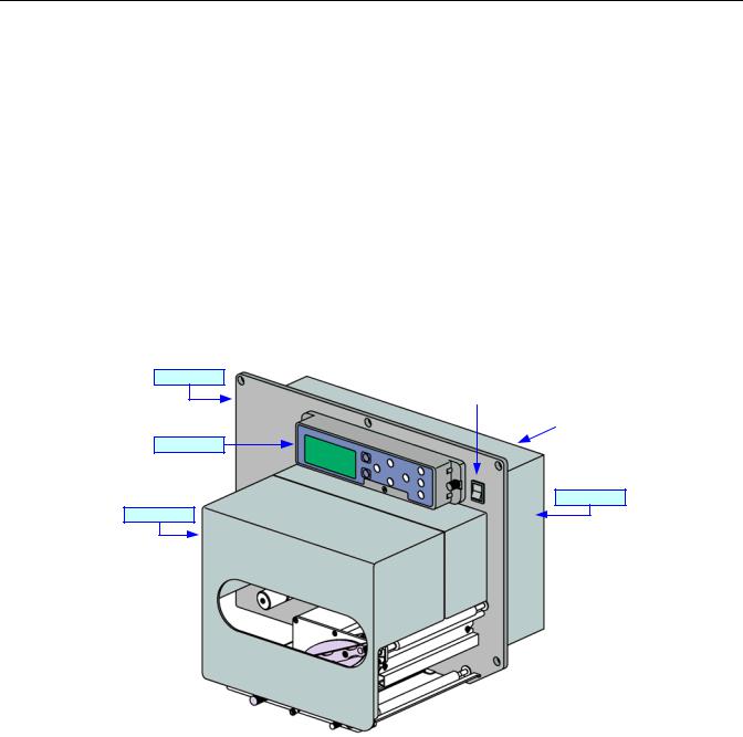
GENERAL DESCRIPTION
The SATO Lt408, OEM print engine has been designed and manufactured to meet the needs of the entry-level print apply market. The entry-level market can be generally defined as small to mid-sized manufacturers with low throughput, light-duty applications. These applications do not require the feature set found on standard OEM print engines that usually make capital investment unjustifiable. The Lt408 offers this market the opportunity to automate the labeling function with a system specified for their requirements and priced within their reach.
The Lt408 follows the SATO OEM print engine concept. The print engine, when integrated with an applicator system provides low-throughput, light-duty applications with automated, yet affordable, print/apply labeling solutions. Because the OEM print engine is a single-piece module, it can be easily and quickly removed for off-line servicing or for complete module replacement. Like all SATO OEM print engines, the Lt408 includes an applicator interface port to provide the required synchronization and messaging between the printer and the applicator.
When specified for suitable applications, the SATO Lt408 print engine is designed to provide years of reliable labeling operations.
Center Frame
Power Switch |
|
Rear Cover |
|
|
|
|
|
Operator Panel
Side Cover
Front Cover
Figure 1-1a, Primary Components
Lt408 Operator Manual |
1-3 |
PN: 9001152A |
Unit 1: Introduction
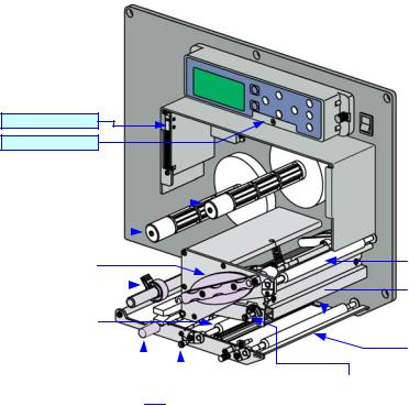
Cover Open Sensor
Potentiometer Access
Ribbon Rewind Spindle |
|
|
|
|
|
|
|
|
|
|
|
|
||
|
|
|
|
|
|
|
|
|
|
|
|
|
|
|
|
|
|
|
|
|
|
|
|
|
|
|
|
|
|
Ribbon Supply Spindle |
|
|
|
|
|
|
|
|
|
|
|
|
|
|
|
|
|
|
|
|
|
|
|
|
|
|
|
|
|
|
|
|
|
|
|
|
|
|
|
|
|
|
|
|
|
|
|
|
|
|
|
|
|
|
|
|
|
Ribbon Roller |
|
Print Head Latch |
|
|
|
|
|
|
|
|
|
|
|
|||
|
|
|
|
|
|
|
|
|
|
|
|
|
|
|
Media Guide |
|
|
|
|
|
|
|
|
|
|
|
|
Front Platen Roller |
|
|
|
|
|
|
|
|
|
|
|
|
|
|||
|
|
|
|
|
|
|
|
|
|
|
|
|
|
|
|
|
|
|
|
|
|
|
|
|
|
|
|
|
|
|
|
|
|
|
|
|
|
|
|
|
|
|
|
|
Feed Roller |
|
|
|
|
|
|
|
|
|
|
|
|
|
|
|
|
|
|
|
|
|
|
|
|
|
|
|
|
|
|
|
|
|
|
|
|
|
|
|
|
|
|
Dispenser Bar |
|
|
|
|
|
|
|
|
|
|
|
|
|
|
|
|
|
|
|
|
|
|
|
|
|
|
|
|
|
|
|
|
|
|
|
|
|
|
|
Pressure Plate Release Knob |
|
Print Head Release Knob |
|
|||
|
|
|
|
|
|
|
|
|
|
|||||
|
|
|
|
|
|
|
|
|
|
|
|
|
|
|
|
|
|
|
|
Label Sensor Adjustment Knob |
|
|
|
|
|
|
|||
|
|
|
|
|
|
|
|
|
|
|
||||
Figure 1-1b, Primary Components
Lt408 Operator Manual |
1-4 |
PN: 9001152A |
Unit 1: Introduction
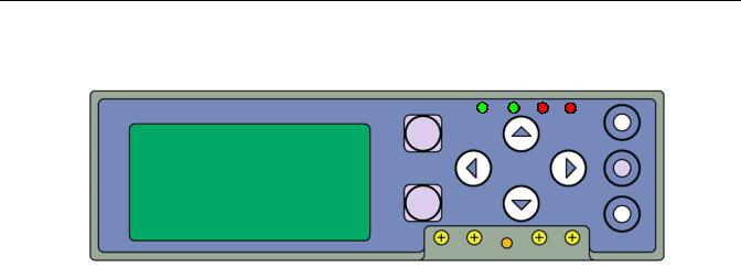
CONTROL FEATURES
This chapter identifies the interactive control features of the printer. These functions are defined generally here. More specific explanations will be found throughout this manual on how to use them.
FUNCTION
LINE
ENTER
LCD DISPLAY
FEED |
CANCEL |
|
Figure 1-2, Operator Panel |
|
|
OPERATOR PANEL FEATURES |
|
|
|
LED |
DEFINITION |
|
|
POWER |
Illuminates green when the printer is powered on. Terminates when powered off. |
|
|
ONLINE |
Illuminates green when the printer is in an online state. Terminates when the printer goes offline. |
|
|
LABEL |
Off = Normal state. |
|
Red Constant = When a Label Error has occurred. |
|
|
RIBBON |
Off = Normal state. |
|
Red Flashing = Ribbon supply is low. |
|
Red Constant = When a Ribbon Error has occurred. |
|
|
KEYS |
DEFINITION |
|
|
LINE |
Moves the printer from an online to offline state and vise-versa. Has other special functions as |
|
identified in flow charts through this manual where applicable. |
FEED |
Advances the label media when pressed. Has other special functions as identified in flow charts |
|
through this manual where applicable. |
|
|
FUNCTION |
Pressing steps the LCD back to a previous menu. Has other special functions as identified in flow |
|
charts through this manual where applicable. |
|
|
ENTER |
Used to select a menu option and to advance the menu screen accordingly. Has other special |
|
functions as identified in flow charts throughout this manual where applicable. |
CANCEL |
Pressing steps the LCD back to a previous menu. Has other special functions as identified in flow |
|
charts through this manual where applicable. |
|
|
ARROWS |
Allows the operator to scroll through various menus and menu options. Has other special |
|
functions as identified in flow charts through this manual where applicable. |
|
|
POTENTIOMETERS |
DEFINITION |
|
|
VOLUME |
Allows volume control of the printer’s audible alarm. |
|
|
PITCH |
For adjusting the pint position. |
|
|
OFFSET |
Adjusts the peel or dispense stop position. |
|
|
DARKNESS |
Adjusts print density resulting in a lighter or darker image. |
|
|
Lt408 Operator Manual |
1-5 |
PN: 9001152A |
TECHNICAL DATA
•Physical Characteristics
•Power
•Enviromental
•Processing
•Media
•Ribbon
•Sensing
•Interface Modules
•Character Font Capabilities
•Barcode Capabilities
•Regulatory Approvals
Lt408 Operator Manual |
2-1 |
PN: 9001152A |
|
|
Unit 2: Technical Data |
|
|
|
PHYSICAL CHARACTERISTICS |
|
|
|
|
|
Width |
|
12.99 Inches (330 mm) |
Height |
|
10.63 Inches ( 270 mm) |
Depth |
|
10.67 Inches ( 271 mm) |
Weight |
|
21.38 Pounds (9.7 Kg) |
|
|
|
POWER |
|
|
|
|
|
Input Voltage |
|
100-240 Volts AC +/- 10%, 50/60 Hertz +/-5% |
Power Consumption |
|
180 Watts (operating) |
|
|
|
ENVIRONMENTAL |
|
|
|
|
|
Operating Temperature |
|
4 to 104°F (5° to 40°C) |
Storage Temperature |
|
-4 to 140°F (-20° to 60°C) |
Storage Humidity |
|
15 to 85% RH Non-Condensing |
Operating Humidity |
|
15 to 85% RH Non-Condensing |
|
|
|
PROCESSING |
|
|
|
|
|
CPU |
|
32 Bit RISC |
FLash ROM |
|
4 Megabytes |
SDRAM |
|
16 Megabytes |
FRAM |
|
32 Kilobytes |
Receive Buffer |
|
2.95 Megabytes |
|
|
|
COMMAND |
|
|
|
|
|
Standard |
|
SATO Barcode Printer Language (SBPL) |
|
Intelligent Command |
|
|
|
|
Non-Standard |
|
N/A |
|
|
|
INTERFACE MODULES |
|
|
|
|
|
Enhanced Parallel Port |
|
IEEE1284 (ECP Compatible) |
Serial Port |
|
RS232C (9600 to 57,600 bps) |
|
RS422/485 (9600 to 57600 bps) |
|
|
|
|
Universal Serial Bus |
|
USB Adapter (12 Mbps) |
LAN |
|
10BASE-T/100BASE-TX Automatic Switching |
Ethernet (Wireless LAN) |
|
802.11B Wireless Wi-Fi |
Centronics Parallel Port |
|
Centronics |
|
|
|
REGULATORY |
|
|
|
|
|
Safety |
|
MET, cMET, NEMKO, CCC |
Radiant Noise |
|
VCCI (Class B), FCC (Class B), EN 55022 (Class B) |
Efficiency |
|
International Energy Star |
|
|
|
Lt408 Operator Manual |
2-2 |
PN: 9001152A |
|
Unit 2: Technical Data |
|
|
|
|
SENSING |
|
|
|
|
|
Gap |
Adjustable |
|
Reflective Eye-Mark |
Adjustable |
|
Ribbon Near End |
Enable/Disable |
|
Media Out |
Constant |
|
Cover Open |
Constant |
|
|
|
|
|
||
|
|
|
Method |
Direct Thermal / Thermal Transfer |
|
Maximum Speed (selectable) |
2, 3, 4, 5, 6 Inches Per Second (50.8-152.4 mm) |
|
Print Module (dot size) |
.0049 Inches (.125 mm) |
|
Resolution |
203 Dots Per Inch (8 dpmm) |
|
Maximum Print Width |
4.10 Inches (104 mm) |
|
Maximum Print Length |
49.17 Inches (1249 mm) |
|
|
|
|
MEDIA |
|
|
|
|
|
Width |
Media Width: 1.00 to 4.41 Inches (25.4-112 mm) |
|
Media Width with Backing Paper: 1.125 to 4.53 Inches (28.6-115 mm) |
||
|
||
Length (Pitch) |
Media Length: 0.59 to 49.29 Inches (15-1252 mm) |
|
Media Length with Backing Paper: 0.71 to 49.41 Inches (18-1255 mm) |
||
|
||
Type |
Roll |
|
Eye-Mark or Gap |
||
|
||
Thickness |
0.003 to 0.010 Inches (0.08 - 0.26 mm) |
|
|
|
|
RIBBON |
|
|
|
|
|
Width |
Minimum: 0.98 Inches (25 mm) |
|
Maximum: 4.37 Inches (111 mm) |
||
|
||
Length |
1476 Feet (450 M) |
|
Wound |
Face In / Face Out. |
|
Roll Diameter |
3.34 Inches (85 mm) |
|
Core Diameter |
1 Inch (25.4 mm) |
|
|
|
Lt408 Operator Manual |
2-3 |
PN: 9001152A |
|
|
Unit 2: Technical Data |
|
|
|
CHARACTER FONT CAPABILITIES |
|
|
|
|
|
MATRIX FONTS |
|
|
|
|
|
XU |
|
5 dots W x 9 dots H (Helvetica) |
XS |
|
17 dots W x 17 dots H (Univers Condensed Bold) |
XM |
|
24 dots W x 24 dots H (Univers Condensed Bold) |
OA Font (OCR-A) |
|
15 dots W x 22 dots H |
OB Font (OCR-B) |
|
20 dots W x 24 dots H |
AUTO SMOOTHING FONTS |
|
|
|
|
|
XB |
|
48 dots W x 48 dots H (Univers Condensed Bold) |
XL |
|
48 dots W x 48 dots H (Sans Serif) |
VECTOR FONT |
|
|
|
|
|
|
|
Proportional or Fixed Spacing |
|
|
Font Size 50 x 50 dots to 999 x 999 dots |
|
|
Helvetica, 10 Font Variations |
AGFA RASTER FONTS |
|
|
|
|
|
A Font |
|
CG Times, 8 to 72 pt. |
B Font |
|
CG Triumvirate, 8 to 72 pt. |
DOWNLOADABLE FONTS |
|
|
|
|
|
|
|
N/A |
CHARACTER CONTROL |
|
|
|
|
|
|
|
Expansion up to 12 x in either the X or Y coordinates. |
|
|
Character Pitch Control |
|
|
Line Space Control |
|
|
Journal Print Facility |
|
|
0, 90, 180, and 270 Degree Rotation |
|
|
|
Lt408 Operator Manual |
2-4 |
PN: 9001152A |

Unit 2: Technical Data
BAR CODE CAPABILTIES
|
UPC A/E |
|
JAN 8/13 |
|
EAN 8/13 |
|
Code 39 |
|
Code 93 |
|
Code 128 |
Linear Bar Codes |
Interleaved 2 of 5 |
Industrial 2 of 5 |
|
|
Matrix 2 of 5 |
|
Bookland |
|
RSS-14 |
|
MSI |
|
POSTNET |
|
UCC/EAN 128 |
|
NW-7 (Codabar) |
|
QR Code |
|
Data Matrix |
Two Dimemsional |
Maxi Code |
|
PDF417 |
|
Synthetic Symbol |
Ratios |
1:2, 1:3, 2:5, User definable bar widths |
Bar Height |
4 to 999 dots, User progammable |
Rotation |
0, 90, 180, and 270 Degrees |
Sequential Numbering |
Sequential numbering of both numerics and bar codes |
Expansion Ratio of Character |
Height: 1-12 times, Width: 1-12 times |
Graphics |
Full dot addressable graphics, SATO Hex/Binary, BMP or PCX formats |
Form Overlay |
Form overlay for high-speed editing of complex formats |
|
|
Lt408 Operator Manual |
2-5 |
PN: 9001152A |

INSTALLATION
•Unpacking & Parts Identification
•Printer Installation
•Operational Mode Selection
•Interface Selection
•Accessories Installation
Lt408 Operator Manual |
3-1 |
PN: 9001152A |
Unit 3: Installation
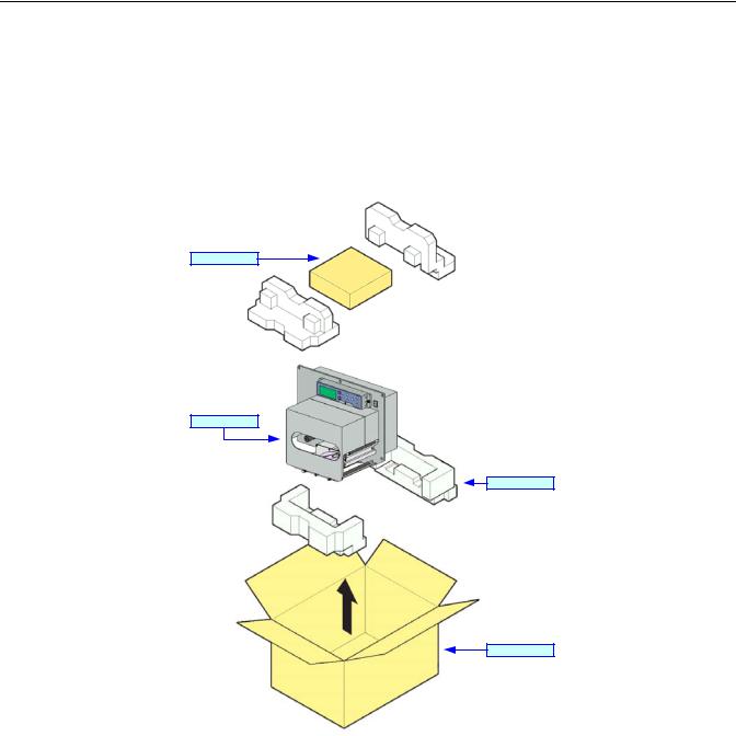
UNPACKING & PARTS IDENTIFICATION
Unpack the printer as directed in the folowing procedure.
1.Place the shipping container (box) upright on a stable, flat surface.
2.Open the box, remove any loose items and the first layer of packing material.
3.Carefully lift the printer and accessories from the box and place them on a stable, flat surface.
4.Remove the plastic covers from the packed items and visually inspect for physical damage.
5.Ensure all components are present as dictated on the Packing List.
6.Report damaged property to the shipping carrier.
Accessory Box
Printer
Cushion
Shipping Box
Figure 3-1, Unpacking
Lt408 Operator Manual |
3-2 |
PN: 9001152A |
Unit 3: Installation
PRINTER INSTALLATION
This chapter provides guidance on how to station, connect, and load the printer once unpacked. Following printer setup, proceded to the next chapter for information on interface selection.
SITE LOCATION
•Stationed away from hazardous materials.
•Stationed within an enclosed structure that conforms to the printer’s enviromental requirements.
•Stationed within operational distance of the host based on interface specifications.
•Stationed to allow unimpeded access to the printer for operation, loading, and maintenance.
INSTALLATION REQUIREMENTS
The printer has five bores in its center frame for the purpose of mounting to a support structure. Refer to the following list of mounting requirements.
•The support structure must be firmly secured to the floor or production machinery.
•The support structure must be sturdy and stable so as to prevent unnecessary movement or vibration.
•The printer is to be mounted to the support structure using attaching hardware design to accommodate the printer’s weight, as well as, the prevailing operational and enviromental conditions within the facility.
•A power supply recepticle or junction box is to be properly secured within regulated proximity to the printer.
•The power supply is to be metered condusive to the printer’s design requirements.
•The printer must be installed so that its output side is within the designated distance and height relative to the applicator.
•Media supply dispensers must be mounted or placed with operational distance of the printer’s input side.
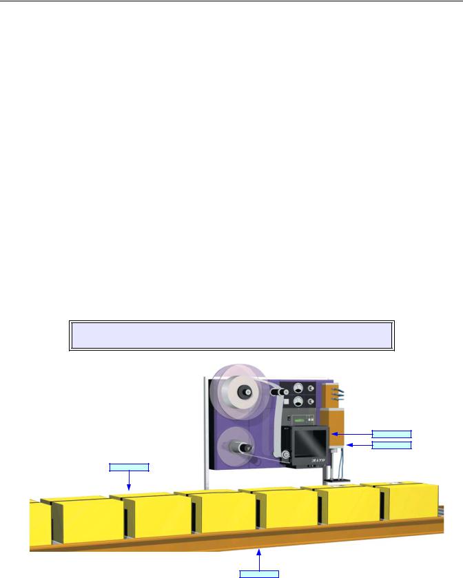
NOTE: Figures 3-2 and 3-3 are to be used as instructional displays only and are not to be literally interpretted as precise examples.
Printer
Applicator
Packaging
Production Line
Figure 3-2, Typical Printer/Applicator Process
Lt408 Operator Manual |
3-3 |
PN: 9001152A |

Unit 3: Installation
Figure 3-3, Printer Mounting
Host Computer
Breaker Box
Applicator
|
|
|
OR |
Power Cord |
|||

 Interface Cable
EXT Interface
Printer
Interface Card
Figure 3-4, Printer Connection
ATTENTION: Figure 3-4 displays the printer interfaced with a host computer. However, the printer may also be interfaced with a PLC, keyboard, scanner, etc.
Lt408 Operator Manual |
3-4 |
PN: 9001152A |
Unit 3: Installation
MEDIA SELECTION
The size and type of labels to be printed should have been taken into consideration before printer purchase. Ideally, the media width will be equal to, or just narrower than, the print head. Using media that does not cover the print head will allow the platen roller to tread upon its surface resulting in premature wear. The media edge will also wear a groove in the platen roller affecting print quality.
There are two types of media that may be used: thermal transfer and direct thermal. Thermal transfer media requires the use of ribbon stock for print application. In such a scenario, it is the ribbon stock (carbon paper) that contains the ink that will be transfered to the media.
Direct thermal media has thermally reactive material embedded within and is brought to the surface through heat penetration by print head contact. Only load ribbon stock into the printer if that media type is to be used.
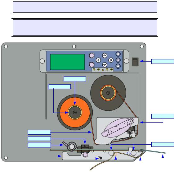
RIBBON LOADING
To load ribbon stock, unlatch the print head and remove exhausted ribbon stock if applicable. Insert an unused ribbon roll, with ribbon core, fully onto the ribbon supply boss (left) and an empty core onto the ribbon rewind boss (right). Route the ribbon’s free end around the print assembly and tape it to the blank core on the rewind boss. Rotate the core a couple of times while holding the boss stationary to take up take up slack. Refer to Figure 3-5 for visual assistance.
WARNING: AVOID PHYSICAL CONTACT WITH THE PRINT HEAD TO PREVENT
BURNED FINGERS/HANDS AND COMPONENT DAMAGE.
NOTE: Properly installed ribbon stock will be oriented so that its dull, ink side is facing the printer chassis while the ribbon is dispensed and taken up on the right side of each roll. The non-ink side of the riibon stock is the shiniest of the two surfaces.
Power Switch
Ribbon Core
Ribbon Boss
Print Assembly
Ribbon Stock
Label Sensor
Media Guide
Platen Roller
|
|
|
|
|
|
|
|
|
|
|
|
|
|
|
|
|
|
|
|
|
|
|
|
|
|
|
|
|
|
|
|
|
|
Label Media |
|
||
|
|
|
|
|
|
|
|
|
|
|
|
|
|
|
|
|
|
|
|
|
|
|
|
|
|
|
|
|
|
|
|
|
|
|
|
|
|
|
Printer Chassis |
|
Pressure Roller Release |
|
Pressure Roller |
|
Paper Backing |
|
|
|
|
|||||||
|
Figure 3-5, Ribbon & Media Loading |
|
|
|
|
|
|
|||||||||||
Lt408 Operator Manual |
3-5 |
|
|
|
|
|
|
|
|
|
|
PN: 9001152A |
||||||
Unit 3: Installation
MEDIA LOADING
To load label media, unlatch the print head and remove any remnants that may exist of the prior media supply. Feed the free end of the media from the printer’s left side, beneath the shaft of the media guide, between the upper and lower halves of the label sensor, across the top of all forthcoming rollers, and through to protrude six or more inches beyond the printer chassis.
Ensure the media is flush against the printer’s back side (toward the center wall) and then adjust the media guide inward until it almost makes contact with the media’s backing paper.
Remove all labels from the backing paper that extend beyond the printer chassis and relatch the print head.
Lift upward on the pressure roller release knob (purple) and allow the pressure roller plate to fall to a vertical position. Route the backing paper’s free end around the front of the printer chassis, beneath the front platen roller and onward between the second platen roller and the pressure roller. Pull the free end of the backing paper to remove all slack while lifting the pressure plate until latched. Refer to Figures 3-5 and 3-6 for visual assistance.
WARNING: AVOID PHYSICAL CONTACT WITH THE PRINT HEAD TO PREVENT
BURNED FINGERS AND HANDS.
NOTE: Properly installed label media will be oriented so that the label side is upward and the backing paper is downward resting upon the printer chassis.
NOTE: Refer to the Printer Configuration unit of this manual for media configuration instructions and the Adjustment chapter of the Maintenance unit for label sensor adjustment instructions as necessary.
Ribbon Boss |
|
Print Head Latch |
|
|
|
|
|
|
|||
|
|
|
|
|
|
|
|
|
|
|
|
Guide Shaft
|
|
|
|
|
|
|
|
|
|
|
|
|
|
|
|
|
|
|
|
|
|
|
|
|
|
|
|
|
|
|
|
|
Center Wall |
|
Label Media |
|
Media Guide |
|
Pressure Roller Release |
||||
Figure 3-6, Media Loading
Lt408 Operator Manual |
3-6 |
PN: 9001152A |

Unit 3: Installation
OPERATIONAL MODE SELECTION
There are two modes of printer operation: Dispense or Continuous. The difference between the two is the way that the label and paper backing is ejected. Before printer configuration, one must determine which mode will be used. This chapter identifies and defines the functional differences between the two.
DISPENSE MODE
With this method of operation, after printing, the printer feeds the first (outermost) label so that it is fully extended out of the printer’s front for dispensing. Printing of the next label will not begin until the prior printed label has been removed. This mode of operation is specifically suited for the use of automated machinery to remove the printed and dispensed label to apply to packaging, etc.
Upon removal of the prior printed label, the printer repositions the media so that the next label in line may be printed, then prints. The before-mentioned cycle, repeats for each consecutive label.
Printer configuration for the backfeed function may be found in the Advanced Mode of the Configuration unit of this manual. Refer to the Table of Contents for the page number.
CONTINUOUS MODE
With this method of operation, the media remains in position for printing at all times. To do so, means that the previous printed label is never in proper position for dispensing and thusly, must be manually removed form the printer rather than through the application of automated machinery.
Printer configuration for Continuous mode of operation may be found in the Advanced Mode of the Configuration unit of this manual. Refer to the Table of Contents for the page number.
ATTENTION: Refer to the Printer Configuration unit of this manual to program the printer’s internal memory to suit individual needs using the printer’s integrated menu options. Refer to the Programming Reference document to remotely program the printer’s features and functions through a host system.
Lt408 Operator Manual |
3-7 |
PN: 9001152A |
Unit 3: Installation
INTERFACE SELECTION
This unit presents the printer interface types and their specifications. These specifications include detailed information to assist in the selection of the most appropriate method for the printer to interface with the host. The five acceptable interface methods are:
•RS232C High-Speed Serial
•IEEE1284 Parallel
•Universal Serial Bus (USB)
•Local Area network (LAN) Ethernet
•802.11b Wireless
Following the selection of the desired interface, proceed to the next unit for instructions on how to Configure the printer for that interface type.
WARNING: NEVER CONNECT OR DISCONNECT INTERFACE CABLES (OR USE
A SWITCH BOX) WITH POWER APPLIED TO EITHER THE HOST OR THE
PRINTER. THIS MAY CAUSE DAMAGE TO THE INTERFACE CIRCUITRY IN THE
PRINTER/HOST AND IS NOT COVERED BY WARRANTY.
NOTE: Some hosts monitor the Request-To-Send (RTS) signal (pin 4 of 25) to determine if the printer is ready to receive data. Since the printer does not generate this signal, the RTS line must be held true (high) in order to allow communication. This can be performed by connecting the RTS pin to the Clear-To-Send (CTS) signal (pin 5 of 25).
Figure 3-7, Interface Installation
Lt408 Operator Manual |
3-8 |
PN: 9001152A |
|
|
|
|
|
|
Unit 3: Installation |
|
RS232C HIGH-SPEED SERIAL INTERFACE |
|||||||
|
|
|
|
|
|
|
|
|
|
|
|
INTERFACE SPECIFICATIONS |
|||
|
|
|
|
|
|
||
Asynchronous ASCII |
|
Half-duplex communication |
|||||
|
|
|
|
Bi-Directional Communication |
|||
|
|
|
|
|
|
||
Data Transmission Rate |
|
9600, 19200, 38400, 57600 bps |
|||||
|
|
|
|
|
|
||
Transmission Form |
|
Start, b1, b2, b3, b4, b5, b6, b7, b8, Stop (b8 will be omitted if using 7 bit oriented) |
|||||
|
|
|
|
|
|
|
|
Data Length |
|
|
7 or 8 bit (selectable) |
|
|||
|
|
|
|
|
|
|
|
Stop Bit |
|
|
1 or 2 bit (selectable) |
|
|||
|
|
|
|
|
|
|
|
Parity Bit |
|
|
ODD, EVEN, NONE (selectable) |
||||
|
|
|
|
|
|
|
|
Codes Used |
|
|
ASC II Character Codes: 7 bits, Graphics: 8 bits |
||||
|
|
|
|
|
|
||
Control Codes |
|
STX (02H), ETX (03H), ACK (06H), NAK (15H) |
|||||
|
|
|
|
|
|
||
Connector (Printer Side) |
|
DB-25S Male (equivalent) |
|||||
|
|
|
|
|
|
||
Cable Connector |
|
DB-25P Female (equivalent) |
|||||
|
|
|
|
|
|
||
Cable Length |
|
5 meters or less. |
|
||||
|
|
|
|
|
|
||
Signal Levels |
|
High = +5V to +12V, Low = -5V to -12V |
|||||
|
|
|
|
|
|
|
|
Protocol |
|
|
Ready/Busy, X-On/X-Off, Protocol for Driver, Status4 |
||||
|
|
|
|
|
|
|
|
|
|
|
|
|
|
|
|
|
|
|
|
|
|
DIPSWITCH SETTINGS |
|
|
|
|
|
|
|
|
|
SWITCH |
|
COMPONENT |
|
|
|
|
SETTINGS |
|
|
|
|
|
|
|
|
1 |
|
Data Bit |
|
ON |
|
7 Bits |
|
|
|
|
|
|
|
||
|
|
OFF |
|
8 Bits |
|||
|
|
|
|
|
|||
|
|
|
2 |
|
3 |
|
|
|
|
|
|
ON |
|
ON |
Reserved |
2 & 3 |
|
Parity |
|
|
|
|
|
|
|
ON |
|
OFF |
ODD |
||
|
|
|
|
|
|
|
|
|
|
|
|
OFF |
|
ON |
EVEN |
|
|
|
|
|
|
|
|
|
|
|
|
OFF |
|
OFF |
NONE |
4 |
|
Stop Bit |
|
ON |
|
2 Bits |
|
|
|
|
|
|
|
||
|
|
OFF |
|
1 Bit |
|||
|
|
|
|
|
|||
|
|
|
5 |
|
6 |
|
|
|
|
|
|
ON |
|
ON |
57600 bps |
5 & 6 |
|
Baud Rate |
|
|
|
|
|
|
|
ON |
|
OFF |
38400 bps |
||
|
|
|
|
|
|
|
|
|
|
|
|
OFF |
|
ON |
19200 bps |
|
|
|
|
|
|
|
|
|
|
|
|
OFF |
|
OFF |
9600 bps |
|
|
|
7 |
|
8 |
|
|
|
|
|
|
ON |
|
ON |
Reserved: Status2 & 3 (when compatible mode is OFF) |
7 & 8 |
|
Protocol |
|
|
|
|
|
|
|
ON |
|
OFF |
Protocol for Driver, Status5 |
||
|
|
|
|
|
|
|
|
|
|
|
|
OFF |
|
ON |
X-ON/X-OFF |
|
|
|
|
|
|
|
|
|
|
|
|
OFF |
|
OFF |
Ready/Busy |
|
|
|
|
|
|
|
|
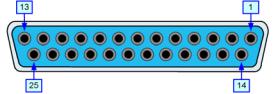
Figure 3-8, Serial Connector Pin Assignments
Lt408 Operator Manual |
3-9 |
PN: 9001152A |

|
|
Unit 3: Installation |
|
|
|
|
|
READY/BUSY INTERFACE SIGNALS |
|
|
|
PIN |
DIRECTION |
SIGNAL DEFINITION |
|
|
|
1 |
Reference |
FG (Frame Ground) |
2 |
To Host |
TD (Transmit Data) - Data from the printer to the host computer. Sends X-On/X-Off characters |
|
|
or status data (bi-directional protocols). |
3 |
To Printer |
RD (Receive Data) - Data to the printer from the host computer. |
4 |
To Host |
RTS (Request to Send) - Used with Ready/Busy flow control to indicate an error condition. |
|
|
RTS is high and remains high unless the print head is open (in this case, RTS would return to |
|
|
the high state after the print head is closed and the printer is placed back on-line) or an error |
|
|
condition occurs during printing (e.g., ribbon out, label out). |
5 |
To Printer |
CTS (Clear to Send) - When this line is high, the printer assumes that data is ready to be |
|
|
transmitted. The printer will not receive data when this line is low. If this line is not being used, |
|
|
it should be tied high (to pin 4). |
6 |
To Printer |
DSR (Data Set Ready) - When this line is high, the printer will be ready to receive data. This |
|
|
line must be high before data is transmitted. If this line is not being used, it should be tied high |
|
|
(to pin 20). |
7 |
Reference |
SG (Signal Ground) |
20 |
To Host |
DTR (Data Terminally Ready) - This signal applies to Ready/Busy flow control. The printer is |
|
|
ready to receive data when this pin is high. It goes low when the printer is off-line, either |
|
|
manually or due to an error condition, and while printing in the single job buffer mode. It will |
|
|
also go low when the data in the buffer reaches the buffer near full level. |
|
|
|
READY/BUSY CABLE REQUIREMENTS
DB9 |
DB25 |
HOST |
DIRECTION |
DB25 |
PRINTER |
|
|
|
|
|
|
1 |
1 |
FG (Frame Ground) |
Bi-Directional |
1 |
FG (Frame Ground) |
|
|
|
|
|
|
2 |
3 |
RD (Receive Data) |
To Host |
2 |
TD (Transmit Data) |
|
|
|
|
|
|
3 |
2 |
TD (Transmit Data) |
To Printer |
3 |
RD (Receive Data) |
|
|
|
|
|
|
8 |
5 |
CTS (Clear To Send) |
To Printer DB9-6 |
4 |
RTS (Request To Send) |
|
|
|
|
|
|
4 |
20 |
DTR (Data Terminal Ready) |
To Printer DB9-4 |
5 |
DSR (Data Set Ready) |
|
|
|
|
|
|
6 |
6 |
DSR* (Data Set Ready) |
To Host |
6 |
DTR (Data Terminal Ready) |
|
|
|
|
|
|
5 |
7 |
SG (Signal Ground) |
Bi-Directional |
7 |
SG (Signal Ground) |
|
|
|
|
|
|
* This connection at the host side of the interface would depend upon the pin that is being used as the Ready/Busy signal by the driving software. Typically, on a PC, it would be either CTS (pin5) or DSR (pin 6) on a DB-25 connector.
X-ON/X-OFF CABLE REQUIREMENTS
Communicates with the host to determine if the printer is ready to receive data by sending “XON” (HEX 11H) or “XOFF” (HEX 13H) code to the TD line. The single and multiple item buffers are switchable in the Interface Mode of the printer.
DB9 |
DB25 |
HOST |
DIRECTION |
DB25 |
PRINTER |
|
|
|
|
|
|
1 |
1 |
FG (Frame Ground) |
Bi-Directional |
1 |
FG (Frame Ground) |
|
|
|
|
|
|
2 |
3 |
RD (Receive Data) |
To Host |
2 |
TD (Transmit Data) |
|
|
|
|
|
|
3 |
2 |
TD (Transmit Data) |
To Printer |
3 |
RD (Receive Data) |
|
|
|
|
|
|
5 |
7 |
SG (Signal Ground) |
Bi-Directional |
7 |
SG (Signal Ground) |
|
|
|
|
|
|
NOTE: Depending on the host used, it may be required to loop CS and RS (maintaining at high-level) on the host side. For more information, refer to the host computer documentation.
Lt408 Operator Manual |
3-10 |
PN: 9001152A |
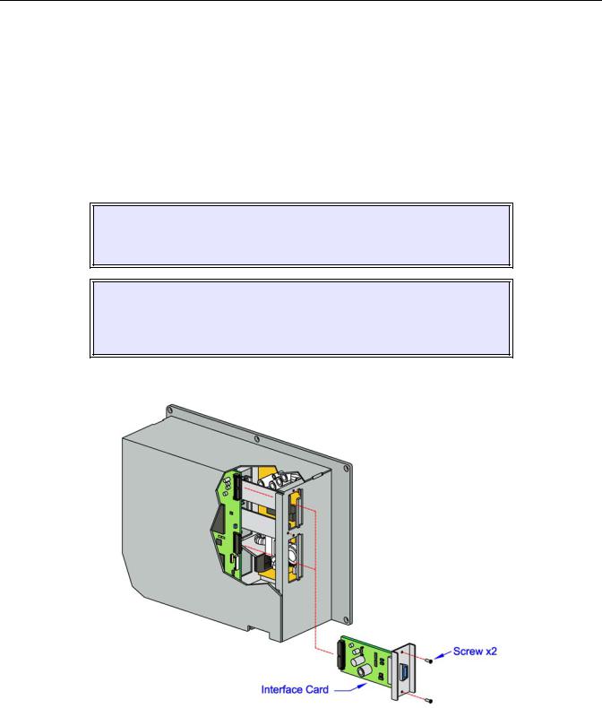
Unit 3: Installation
IEEE1284 PARALLEL INTERFACE
The parallel interface is a plug-in module that can be installed by the user and conforms to IEEE1284 specifications. It automatically detects the IEEE1284 signals and operates in the high speed mode. If the IEEE1284 signals are not detected, it will operate in the slower standard Centronics mode. For this reason, an interface cable and host interface conforming to the IEEE1284 specification must be present to fully utilize the speed capabilities. This interface also operates bi-directionally and can report the status of the printer back to the host.
|
SPECIFICATIONS |
|
|
Printer Connector |
AMP 57-40360 DDK (or equivalent) |
|
|
Cable Connector |
AMP 57-30360 DDK (or equivalent) |
|
|
Cable |
1.5 meter or less |
|
|
Signal Level |
High = +2.4V to +5.0V, Low = 0V to -0.4V |
|
|
Data Stream |
<ESC>A . . Job#1 . . <ESC>Z<ESC>A . . Job#n . . <ESC>Z |
|
|
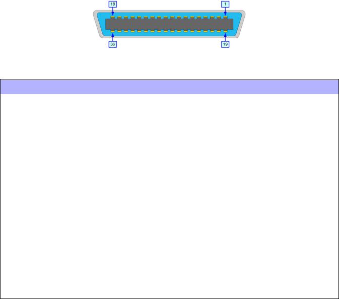
Figure 3-9, Parallel Connector Pin Assignments
PIN ASSIGNMENTS
PIN |
SIGNAL |
|
DIRECTION |
PIN |
SIGNAL |
|
DIRECTION |
|
|
|
|
|
|
|
|
1 |
Strobe |
|
To Printer |
19 |
Strobe Return |
|
Reference |
2 |
Data 1 |
|
To Printer |
20 |
Data 1 Return |
|
Reference |
3 |
Data 2 |
|
To Printer |
21 |
Data 2 Return |
|
Reference |
4 |
Data 3 |
|
To Printer |
22 |
Data 3 Return |
|
Reference |
5 |
Data 4 |
|
To Printer |
23 |
Data 4 Return |
|
Reference |
6 |
Data 5 |
|
To Printer |
24 |
Data 5 Return |
|
Reference |
7 |
Data 6 |
|
To Printer |
25 |
Data 6 Return |
|
Reference |
8 |
Data 7 |
|
To Printer |
26 |
Data 7 Return |
|
Reference |
9 |
Data 8 |
|
To Printer |
27 |
Data 8 Return |
|
Reference |
10 |
ACK |
|
To Host |
28 |
ACK Return |
|
Reference |
11 |
Busy |
|
To Host |
29 |
Busy Return |
|
Reference |
12 |
Ptr Error |
|
To Host |
30 |
PE Return |
|
Reference |
13 |
Select |
|
To Host |
31 |
INIT |
|
From Host |
14 |
AutoFD1 |
|
To Host |
32 |
Fault |
|
To Host |
15 |
Not Used |
|
33 |
|
Not Used |
||
16 |
Logic Gnd |
|
|
34 |
|
Not Used |
|
17 |
FG |
|
Frame Gnd |
35 |
|
Not Used |
|
18 |
+5V (z=24k ohm) |
|
To Host |
36 |
SelectIn1 |
|
From Host |
|
|
|
|
|
|
|
|
1 Signals required for ieee 1284 mode.
Lt408 Operator Manual |
3-11 |
PN: 9001152A |
Unit 3: Installation
UNIVERSAL SERIAL BUS (USB)
The Universal Serial Bus (USB) interface is a Plug-In Interface Module that can be installed by the user. It requires a driver (shipped with each printer that has the interface installed) that must be loaded onto the PC and configured to support USB peripherals using Windows 2000 or above. Details for loading the USB driver are contained in the USB Interface Manual that is shipped with each printer with a USB Optional interface installed. Up to 127 devices may be connected to a USB port using powered hubs.
|
|
|
|
|
|
|
|
ATTENTION: This Interface Type Is Not Compatible With Windows 98 Or Windows |
|
|
|
|
|
Me. |
|
|
|
|
|
|
|
|
|
|
|
|
|
|
|
|
|
|
SPECIFICATIONS |
|
|
|
|
|
|
|
|
Printer Connector |
USB Type B Plug |
|
|
||
|
|
|
|
||
Cable |
10 feet (3 m) maximum |
|
|
||
|
|
|
|
||
Host |
Windows 2000 or above with USB Port |
|
|
||
|
|
|
|
||
Power Supply |
BUS Power through cable |
|
|
||
|
|
|
|
||
Power Consumption |
+5 V at 80 ma |
|
|
||
|
|
|
|
|
|
LOCAL AREA NETWORK (LAN) ETHERNET
A Local Area Network (LAN) interface is an optional Plug-In Interface Module that can be installed by the user. It requires a driver shipped with each printer that has the interface installed. The driver that must be loaded onto the host computer and configured to run one of the supported network protocols using a 10Base-T or 100Base-TX LAN connection. Details for loading the LAN driver are contained in the LAN Interface Manual that is shipped with each printer with a LAN Optional interface installed.
|
SPECIFICATIONS |
|
|
Connector |
RJ-45 Receptacle |
|
|
Cable |
10/100BaseT Category 5 |
|
|
Cable Length |
100 meters or less |
|
|
Power Supply |
Powered from printer |
|
|
Protocol |
Status3 return |
|
Protocol for Driver (cyclic response mode) |
|
Protocol for Driver (ENQ response mode) |
|
Status5 return |
|
|
IP Address |
0.0.0.0 to 255.255.255.255 |
|
|
Subnet Mask |
0.0.0.0 to 255.255.255.255 |
|
|
Gateway Address |
0.0.0.0 to 255.255.255.255 |
|
|
|
DIPSWITCH SETTINGS |
|
|
SWITCH |
SETTING |
|
|
1 |
Reserved (setup prohibited). |
2 |
LAN board EEPROM initialization (configuration). |
3 |
Print configuration details on a label. |
4 |
Print a self-diagmosis of the board onto a label. |
|
|
Lt408 Operator Manual |
3-12 |
PN: 9001152A |

|
Unit 3: Installation |
|
|
|
SOFTWARE SPECIFICATIONS |
|
|
Corresponding Protocol |
TCP/IP |
|
|
Network Layer |
ARP, RARP, IP, ICMP |
|
|
Session Layer |
TCP, UDP |
|
|
Application Layer |
LPD, FTP, TELNET, BOOTP, DHCP |
|
|
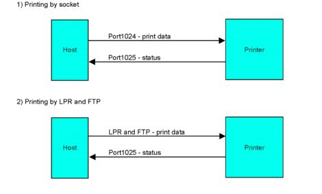
NOTE: Print data can be sent by LPR and FTP of TCP/IP and dedicated socket protocol. Printer status is obtainable by dedicated socket protocol.
NOTE: In the TCP/IP protocol enviroment, LPD and FTP are provided for printing; TELNET for variable setup; ARP, RARP, and BOOTP/DHCP for address setup.
LPD protocol complies with RFC1179 and handles the list of logical printer name as queue name such as lp, sjis, euc. In addition, a banner page can be printed by a proper setup.
When sending the job by LPR, the transmission order of data file/control file within the job will not affect print operation. In addition, if the banner page is specified, it will be added to each data file. Job deletion by LPR is not available.
FTP protocol complies with RFC959 and handles the list of logical printer name as a transfer directory. File transfer to this directory executes print operation. It is possible to specify ASCII(A), Binary(I) and TENEX(L8) as transfer mode - although the mode difference is dependent on the client. A banner page may be printed with a proper setup.
TELNET Complies with RFC854. This operation consists of interactive menu form and enables change and reference of internal setup, and to display status. To change the setup, enter “root” user and password at the time of login. Default of root pasword is set as null (linefeed only).
802.11B WIRELESS
The wireless print server provides easy printer interface with 802.11b Wi-Fi compliant networks free of wired connections. Each printer is shipped with an integrated driver and interface installed. The driver must be loaded onto the host computer and configured to run one of the supported protocols.
|
SPECIFICATIONS |
|
|
Variable Data Rates |
11, 5.5, 2 and 1 Mbps |
|
|
Frequency Band |
2.4 GHz ISM Band |
|
|
Wired Equivalent Privacy |
128 bit, 64 bit (compatible with 40bit), none |
|
|
Sensitivity |
(typ, AAWGN, 8E-2 PER): -91dBm at 1Mbps, -88dBm at 2 Mdps, -87dBm at 5.5Mbps, - |
|
84dBm at 11Mbps. |
|
|
Range |
100m indoors, 300m outdoors |
|
|
Protocols |
TCP/IP, IPX/SPX, Direct Mode IPX/IP, DLC/LLC, NetBEUI, NetBIOS/IP |
|
|
Protocol |
Status3 return |
|
Protocol for Driver (cyclic response mode) |
|
Protocol for Driver (ENQ response mode) |
|
Status5 return |
|
|
IP Address |
0.0.0.0 to 255.255.255.255 |
|
|
Subnet Mask |
0.0.0.0 to 255.255.255.255 |
|
|
Gateway Address |
0.0.0.0 to 255.255.255.255 |
|
|
Communication Mode |
802.11 Ad hoc, Ad hoc, Infrastructure |
|
|
SSID |
Optional alphanumeric character string (up to 32 characters) |
|
|
Channels |
01 to 04 |
|
|
Lt408 Operator Manual |
3-13 |
PN: 9001152A |

Unit 3: Installation
DIPSWITCH SETTINGS
The dipswitches serve to initialize the configuration saved on the Wireless-LAN board, print the configuration, and make a selfdiagnosis. To communicate with the host,set the communication mode by through switches 5 and 6, then set the remaining switches to the OFF position.
Print of configuration and self-diagnsis are operable only on the screen after turning on the printer. Ensure all switches are in the OFF position when operating the printer.
SWITCH |
SETTING |
|
|
1Reserved (setup prohibited).
2LAN board EEPROM initialization (configuration).
3Print configuration details on a label.
4Print a self-diagmosis of the board onto a label.
|
5 |
6 |
|
|
ON |
ON |
Reserved. |
5 & 6 |
|
|
|
ON |
OFF |
Ad hoc |
|
|
|
|
|
|
OFF |
ON |
Infrastructure |
|
|
|
|
|
OFF |
OFF |
802.11 Ad hoc |
|
|
|
|
NOTE: The communication mode may be set within the printer’s Interface Mode. Go to [Communication] of the Interface Mode to enable setup by either the dipswitches or through the Interface Mode.
LED INDICATOR STATUS
INDICATOR 1 |
INDICATOR 2 |
INDICATOR 3 |
DESCRIPTION |
|
|
|
|
ON |
OFF |
OFF |
Weak Signal (1-50%) |
|
|
|
|
ON |
ON |
OFF |
Moderate Signal (50-75%) |
|
|
|
|
ON |
ON |
ON |
Strong Signal (75-100%) |
|
|
|
|
OFF |
OFF |
ON |
802.11 Ad hoc |
|
|
|
|
OFF |
ON |
OFF |
Ad hoc |
|
|
|
|
|
SOFTWARE SPECIFICATIONS |
|
|
Corresponding Protocol |
TCP/IP |
|
|
Network Layer |
ARP, RARP, IP, ICMP |
|
|
Session Layer |
TCP, UDP |
|
|
Application Layer |
LPD, FTP, TELNET, BOOTP, DHCP |
|
|
NOTE: Print data can be sent by LPR and FTP of TCP/IP and dedicated socket protocol. Printer status is obtainable by dedicated socket protocol.
NOTE: In the TCP/IP protocol enviroment, LPD and FTP are provided for printing; TELNET for variable setup; ARP, RARP, and BOOTP/DHCP for address setup.
LPD protocol complies with RFC1179 and handles the list of logical printer name as queue name such as lp, sjis, euc. In addition, a banner page can be printed by a proper setup.
When sending the job by LPR, the transmission order of data file/control file within the job will not affect print operation. In addition, if the banner page is specified, it will be added to each data file. Job deletion by LPR is not available.
FTP protocol complies with RFC959 and handles the list of logical printer name as a transfer directory. File transfer to this directory executes print operation. It is possible to specify ASCII(A), Binary(I) and TENEX(L8) as transfer mode - although the mode difference is dependent on the client. A banner page may be printed with a proper setup.
TELNET Complies with RFC854. This operation consists of interactive menu form and enables change and reference of internal setup, and to display status. To change the setup, enter “root” user and password at the time of login. Default of root pasword is set as null (linefeed only).
Lt408 Operator Manual |
3-14 |
PN: 9001152A |
Unit 3: Installation
Figure 3-10, Socket Connection Diagram
Lt408 Operator Manual |
3-15 |
PN: 9001152A |
Loading...